EP1439557A1 - Boítier de coupure d'un appareil électrique interrupteur - Google Patents
Boítier de coupure d'un appareil électrique interrupteur Download PDFInfo
- Publication number
- EP1439557A1 EP1439557A1 EP04100060A EP04100060A EP1439557A1 EP 1439557 A1 EP1439557 A1 EP 1439557A1 EP 04100060 A EP04100060 A EP 04100060A EP 04100060 A EP04100060 A EP 04100060A EP 1439557 A1 EP1439557 A1 EP 1439557A1
- Authority
- EP
- European Patent Office
- Prior art keywords
- cut
- assembly
- box
- polar
- switch device
- Prior art date
- Legal status (The legal status is an assumption and is not a legal conclusion. Google has not performed a legal analysis and makes no representation as to the accuracy of the status listed.)
- Granted
Links
- 238000000034 method Methods 0.000 claims abstract description 14
- 239000004020 conductor Substances 0.000 claims description 19
- 238000011144 upstream manufacturing Methods 0.000 claims description 17
- 238000003780 insertion Methods 0.000 claims description 11
- 230000037431 insertion Effects 0.000 claims description 11
- 238000005192 partition Methods 0.000 claims description 11
- 230000005405 multipole Effects 0.000 claims description 3
- 239000007789 gas Substances 0.000 description 11
- 230000000712 assembly Effects 0.000 description 10
- 238000000429 assembly Methods 0.000 description 10
- 239000000470 constituent Substances 0.000 description 4
- 238000013461 design Methods 0.000 description 4
- 238000006073 displacement reaction Methods 0.000 description 2
- 238000012423 maintenance Methods 0.000 description 2
- 210000000056 organ Anatomy 0.000 description 2
- 238000000926 separation method Methods 0.000 description 2
- 230000008033 biological extinction Effects 0.000 description 1
- 238000001514 detection method Methods 0.000 description 1
- 238000010586 diagram Methods 0.000 description 1
- 238000010891 electric arc Methods 0.000 description 1
- 239000011810 insulating material Substances 0.000 description 1
- 238000004519 manufacturing process Methods 0.000 description 1
- 239000000463 material Substances 0.000 description 1
- 238000009527 percussion Methods 0.000 description 1
- 238000007789 sealing Methods 0.000 description 1
- 238000013519 translation Methods 0.000 description 1
Images

Classifications
-
- H—ELECTRICITY
- H01—ELECTRIC ELEMENTS
- H01H—ELECTRIC SWITCHES; RELAYS; SELECTORS; EMERGENCY PROTECTIVE DEVICES
- H01H9/00—Details of switching devices, not covered by groups H01H1/00 - H01H7/00
- H01H9/30—Means for extinguishing or preventing arc between current-carrying parts
- H01H9/34—Stationary parts for restricting or subdividing the arc, e.g. barrier plate
- H01H9/345—Mounting of arc chutes
-
- H—ELECTRICITY
- H01—ELECTRIC ELEMENTS
- H01H—ELECTRIC SWITCHES; RELAYS; SELECTORS; EMERGENCY PROTECTIVE DEVICES
- H01H71/00—Details of the protective switches or relays covered by groups H01H73/00 - H01H83/00
- H01H71/02—Housings; Casings; Bases; Mountings
- H01H71/0207—Mounting or assembling the different parts of the circuit breaker
Definitions
- the present invention relates to an electrical appliance with a low switch voltage, in particular of the contactor, circuit breaker or contactor-circuit breaker type, comprising a breaking box made up of two parts, each part forming a box surrounding arc extinguishing fin blocks for better rigidity and better resistance to gas pressure.
- the invention also relates to a method assembly of such a switch device.
- the switch device comprises a housing made of insulating material with a tank-shaped base, the bottom of which forms a rear face of the device light switch.
- the tank is open at the front so that the constituents of the polar cut-off assemblies (i.e., mobile contact bridge, bridge actuator, contact pressure spring, cage for holding the bridge, arc extinguishing fin blocks, deflectors, etc.) can be introduced at inside the tank from the front.
- the constituents of the polar cut-off assemblies i.e., mobile contact bridge, bridge actuator, contact pressure spring, cage for holding the bridge, arc extinguishing fin blocks, deflectors, etc.
- the polar assemblies of are completely or partially assembled prior to their introduction into the tank.
- the tank is then covered by a cover or cover ensuring in particular the sealing and thus forming a breaking box divided into several switching chambers for the different power poles of the device light switch.
- the cover also carries the trigger system which is likely to activate the mobile contacts of the device.
- This system of trigger can consist for example of a mechanical lock block, a block magnetic break and / or a thermal break block.
- junction between the tank and the cover must be studied carefully because it is subject to strong constraints related to the gas overpressure in particular near the outer end of the fin blocks, corresponding to the area where the gas overpressure is important.
- the opening of the tank of the switch box, and therefore the junction area between the tank and the cover extends over practically the entire front face of the tank, otherwise it would be difficult to insert in the breaking box the various constituents of the polar assemblies cut-off, especially when they are assembled beforehand.
- the surface occupied by this junction zone is important and extends including to the near the end of the finned blocks. This leads to significant efforts due to the pressure which cause mechanical fragility of the switch box which must be compensated in particular by substantial fixing devices to maintain a good seal between tank and cover.
- junction box of the breaking box by reducing the area occupied by the area of junction and stiffening the different parts forming the cutting box.
- the invention describes an electrical switch device comprising a cut-off box intended to receive at least one polar cut-off assembly provided with two arc extinguishing fin blocks located on either side of a contact bridge mobile capable of being actuated along a horizontal axis of movement.
- the box breaking comprises a first element comprising two side walls, a wall rear, a front wall and a bottom formed by a first horizontal face of the switching device, so as to form a tank having a cavity which receives a first fin block of the polar cut-off assembly, and a second element separate from the first element and comprising two side walls, a rear wall, a front wall and a bottom formed by a second horizontal face of the switch device, opposite the first horizontal face, so as to form a tank having a cavity which accommodates the second block of fins of the polar cut-off assembly.
- each element of the breaking box of a device multi-pole switch also has a partition between each pole adjacent, fixed to the rear and front walls and to the bottom of said element.
- each element of the breaking box is preferably made up in a single molded piece.
- the junction zone between the first and the second element of the housing cut is in a plane which is approximately parallel to the first and second horizontal faces of the breaking box, while in the solutions known, this junction zone lies in a substantially vertical plane, perpendicular to the horizontal axis of movement of the contact bridge.
- Another object of the invention is to propose a simple assembly method and fast of such an electrical switch device.
- the assembly method successively comprises a step of insertion of the polar cut-off assemblies inside the first element of the housing break, a step of hooking a trigger system against the first element, then a step of fixing the second element of the breaking box to the first element so as to simultaneously close the breaking box and allow the trigger system lockout.
- the step of hooking up the release includes a step of attaching a mechanical lock block to the first element then a step of attaching a magneto / thermal block to the block mechanical lock.
- an electrical switch device 10 by example of the circuit breaker, contactor or contactor-monopolar type, or multipolar, is responsible for controlling and / or protecting a circuit electrical downstream, by switching polar lines of upstream current 75 to lines downstream current poles 59.
- these upstream current lines 75, respectively downstream 59 are connected to an upstream electrical supply circuit, respectively to a downstream load circuit, via upstream terminal blocks, respectively downstream of the switch device 10 which are not shown in the FIGS.
- Each power pole of the switch device has a set cut-off polar 80, such as that shown diagrammatically in FIG. 4, which includes a bridge movable conductor 83 supporting two movable contacts 84,85 positioned on either side on the other side of a median horizontal axis X.
- the bridge 83 is movable in translation along the axis of X displacement in a forward / backward direction, so that you can separate or paste the movable contacts 84.85 of the bridge 83 with fixed contacts 76.56 upstream and downstream of the switch device.
- the device is said to be in the closed position when the movable contacts are glued against the fixed contacts, making it possible to connect the upstream current lines 75 and downstream 59, and in the open or tripped position when the contacts are separated.
- the polar cut-off assembly 80 comprises also a pusher 78 capable of actuating the movable bridge 83 in the opening direction and a contact pressure spring, not shown, responsible for operating the bridge mobile 83 in the closing direction.
- a pusher 78 capable of actuating the movable bridge 83 in the opening direction
- a contact pressure spring not shown, responsible for operating the bridge mobile 83 in the closing direction.
- Other devices for moving the movable bridge 83 are obviously conceivable.
- the polar cut-off assembly 80 comprises a first 81 and a second 82 block of arc extinguishing fins, the purpose of which is is to channel outwards and facilitate the extinction of electric arcs occurring during the opening between the movable contacts 84, respectively 85, and the contacts corresponding fixed 76, respectively 56.
- Various known organs, such as deflector 89, can also be used to facilitate the dissipation of electric arcs.
- each polar cut-off assembly 80 is previously assembled for reasons of convenience of mounting the various parts which constitute before being installed in a switch box of the switch device 10. It is therefore necessary that this breaking box on the one hand has a sufficient opening for allow easy insertion of the cut-off assembly (s) 80 and on the other hand either capable of ensuring good resistance to gas overpressures, once the device switch assembled.
- the cut-off box of the switch device 10 comprises two distinct elements 20.30.
- the first element 20 of the switch box has two side walls 24.25 substantially parallel, between a rear wall 23 and a front wall 22, and a bottom 21 connecting the vertical walls 22,23,24,25.
- the first element 20 thus forms a first tank, approximately parallelepiped, open on the side which is opposite the bottom 21.
- the cavity 29 of the first tank is susceptible to fully or partially accommodate the first fin block 81 of the assembly or assemblies breaking poles 80.
- the bottom 21 of the first element 20 forms a first face horizontal of the housing of the switch device 10, for example an upper face.
- the second element 30 of the cut-off box has two substantially parallel side walls 34,35, lying between a rear wall 33 and a front wall 32, as well as a bottom 31 connecting the vertical walls 32,33,34,35.
- the second element 30 thus forms a second tank approximately parallelepiped, open on the side which is opposite the bottom 31.
- the cavity 39 of the second tank is capable of fully or partially accommodating the second block fins 82 of the polar cut-off assembly or assemblies 80.
- the bottom 31 of the second element 30 forms a second horizontal face of the housing of the switch device 10, by example a lower face, opposite the upper face 21.
- the two elements 20 and 30 are therefore designed as two half-housings rigid so that, when assembling the device 10, they fit together so as to form a closed breaking box creating breaking chambers in the cavities 29.39. Due to the open tank shape on one side, it is very easy introduce the polar cutout assembly (s) 80 into each half-housing 20.30 of the breaking box.
- fixing means such as latching means 28,38, composed for example of an elastic member 28 of the element 20 whose end can snap into an opening 38 provided in the element 30.
- Other means of fixing such as fixing screws are also possible to hold the two elements 20.30 between them.
- each element 20.30 further comprises a partition 26.36 between each adjacent pole, so as to isolate the poles from each other.
- Each of the partitions 26, respectively 36 is fixed to the rear walls 23, respectively 33, and before 22, respectively 32, as well as at the bottom 21, respectively 31, of the element 20, respectively 30.
- These partitions 26, respectively 36 are substantially parallel to the side walls 24.25, 34.35 respectively and form a casing allowing to define separate cavities 29, respectively 39, thus creating chambers separate cutoffs for each pole.
- FIG. 7 shows a three-pole switch device, each element of which 20.30 therefore has two partition walls 26.36.
- each partition 36 further includes an interior recess into which the corresponding partition 26 is inserted. This creates a overlap between the partitions 26.36.
- This solution presents the advantage of guaranteeing a good seal between the different interrupting chambers 29; 39 of the poles, to respect the vanishing lines between poles and to stiffen the junction between partitions 26 and 36.
- each element 20.30 of the breaking box is made up in a single molded piece of insulating plastic material, which simplifies the manufacture of the switch device and which also ensures a good seal between the different cavities 29.39 of each pole and better rigidity of the elements 20.30.
- the internal dimensions of the two elements 20.30 are studied for that, when they are fixed against each other, they can keep in position the cut-off sets 80 of the different poles placed inside.
- the funds 21.31 of the two elements 20.30 have several openings of openings 27.37 so to allow the evacuation to the outside of the gases from the different interrupting chambers 29,39, at the top and bottom of the switch device 10.
- junction zone between the two elements 20.30 corresponding to the joint between the two assembled elements, lies in an approximately plane horizontal (see Figures 1 and 6), substantially parallel to the bottoms 21.31 of the housing cut.
- the junction area between tank and cover is located at the front of the switch box in a substantially vertical plane, orthogonal to the horizontal displacement axis X.
- the height of the switch box is less than its depth, given the structure and the arrangement of the polar cut-off assemblies 80.
- the surface occupied by the junction zone is therefore significantly smaller than in a conventional solution. Consequently, for a given gas pressure, the pressure forces exerted on the junction zone between the two elements 20.30 are significantly less which allows better mechanical resistance.
- This arrangement also makes it possible to stiffen the different parts of the elements 20.30, in particular at the level of the partitions of separation 26.36.
- the junction area between the two elements 20.30 can be advantageously remote from the external ends 81 ′, 82 ′ of the fin blocks 81, 82, to avoid having to bear too much overpressure. Thanks to this arrangement of the cut-off box in two separate elements 20.30, advantageously obtained from firstly an easy introduction of the pre-assembled polar cut-off assemblies, secondly share better resistance of the pole breaking chambers to the overpressures of gas.
- the side walls 24, 25 and 34, 35 of the elements 20 and 30 form side faces of the housing of the switch device 10.
- the housing of break then constitutes a base of the switch device 10 on which can be including fixed a trigger system.
- means may be available to hang the switch device 10 on any mounting support such as DIN rail or other. In the attached figures, these attachment means are arranged on the rear wall 23 of the element 20.
- the switch device 10 comprises a trigger system constituted one or more function blocks in order to ensure control and / or protection of the downstream electrical circuit.
- the trigger system includes an electro-mechanical 50 magneto / thermal cut-off block for each pole and a mechanical lock block 40.
- the mechanical lock block 40 is provided with a lock 41 which acts on each pusher 78 of the pole, in the opening direction, for example by through a rudder not shown for reasons of simplification.
- an electromechanical magneto / thermal cut-off block 50 is traversed by the power current flowing in the corresponding pole and can include in series a thermal trip device 51, such as a bimetallic strip actuated by a heater, and a magnetic trip device 52, composed of a magnetic coil and a striker, which acts on the movable bridge 83 of the pole in the opening direction by example via a percussion rod passing through the pusher 78, not shown schematically for reasons of simplification.
- the switch device 10 usually includes a upstream fixed conductor 75 forming the polar upstream current line and one of which end has substantially a U shape materialized by two branches 73 and 74 (see Figure 2).
- a branch 74 of the U carries the upstream fixed contact 76 which cooperates with the movable contact 84.
- the upstream conductor 75 is introduced into the switch device 10 by inserting the front wall 22 of the first element 20 of the housing in the interior space located between the two branches 73,74 of the U.
- the branch spacing 73,74 can be designed so that, once inserted, the upstream conductor 75 is maintained by wedging the branches 73.74 around the front wall 22.
- the switching device 10 also includes for each pole a downstream fixed conductor 55, one end of which is substantially U-shaped materialized by two branches 53 and 54 (see Figure 3).
- a branch 54 of the U bears the downstream fixed contact 56 which cooperates with the movable contact 85.
- the downstream conductor 55 is connected in series with the thermal trip device 51, at the magnetic trip device 52 then to the downstream polar line 59.
- the conductor downstream 55 is therefore fixed to the magneto / thermal cut-off block 50 of the pole.
- the front wall 32 of the second element 30 of the breaking box is introduced into the interior space located between the two branches 53,54 of the U of each downstream conductor 55, allowing thus ensuring the maintenance and locking of the trigger system at the same time that the shutdown box closes.
- the branch spacing 53.54 can be designed so that the downstream conductor 55 is held by wedging the branches 53.54 around the front wall 32.
- the fixing of the second element 30 against the first element 20 is carried out preferably by latching means 28,38 or by other means such only screws.
- This step C therefore advantageously allows, in a single operation, the times to fully lock the trigger system, thanks to the front wall 32, and to close the breaking box, by fixing the second element 30 on the first element 20. This gives a simple, quick and efficient method of assembling the switch device.
- An additional fixing step then makes it possible to position a block front face 60 comprising control and / or display members for the switch device 10, at the front of the trigger system 40.50, finally obtain the assembled device 10 as shown in FIGS. 1 and 6.
- each module of the switch device 10 can be designed and assembled separately with each other (polar cutout assembly, lock block, magneto / thermal block, front panel block, etc.), which not only facilitates replacement of one module by another during maintenance operations but this which also makes it easier to design from a single base of electrical devices switches with different functions or the design of a wide range switchgear using certain common modules.
Landscapes
- Breakers (AREA)
- Switch Cases, Indication, And Locking (AREA)
- Arc-Extinguishing Devices That Are Switches (AREA)
Abstract
Description
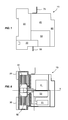
- la figure 1 représente une vue simplifiée de côté d'un exemple d'appareil interrupteur conforme à l'invention,
- la figure 2 détaille une vue en coupe du premier élément du boítier de coupure de l'appareil interrupteur,
- la figure 3 donne un schéma simplifié d'un système de déclenchement avec un bloc serrure mécanique et un bloc magnéto/thermique,
- la figure 4 montre une coupe d'un ensemble polaire de coupure à introduire dans l'appareil interrupteur,
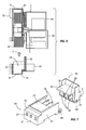
- la figure 5 représente une vue en coupe de l'appareil interrupteur en cours d'assemblage comprenant les constituants des figures 2, 3 et 4, avec le second élément du boítier de coupure de l'appareil interrupteur,
- la figure 6 représente une vue en coupe de l'appareil interrupteur de la figure 1 comprenant les différents constituants de la figure 5 ainsi qu'un bloc face avant,
- la figure 7 montre une vue en perspective couchée des deux éléments d'un boítier de coupure vide d'un appareil interrupteur tripolaire.
- Une première étape d'insertion A de chaque ensemble polaire de coupure 80, préalablement monté, dans une chambre de coupure créée par chaque cavité 29 du premier élément 20 du boítier de coupure. La forme de cuve ouverte du premier élément 20 permet une insertion très facile par l'ouverture de la cuve. Cette étape est schématisée par la flèche A de bas en haut entre la figure 2, représentant le premier élément 20, et la figure 4, représentant un ensemble de coupure 80. Le ou les conducteurs polaires amont 75 sont eux soit insérés dans une étape préliminaire d'insertion, soit insérés durant l'étape A, en particulier s'ils sont préalablement assemblés avec le ou les ensembles polaires de coupure 80. Les branches 74, 73 du U sont positionnées de part et d'autre de la paroi avant 22 du premier élément 20 de manière à maintenir, par exemple par coincement, en position fixe le conducteur amont 75.
- Une deuxième étape d'accrochage B du système de déclenchement 40,50 de l'appareil interrupteur 10 contre le premier élément 20. Cette étape est schématisée par la flèche B entre la figure 2 et la figure 3, représentant un système de déclenchement 40,50. Suivant le nombre de blocs fonctions constituant le système de déclenchement, l'étape B peut être décomposée en plusieurs phases. Dans un appareil 10 dont le système de déclenchement inclut un bloc serrure mécanique 40 et un ou plusieurs blocs de coupure magnéto/thermique 50, l'étape B comprend une première étape d'accrochage du bloc serrure 40 contre la paroi avant 22 du premier élément 20. Le bloc serrure 40 est par exemple introduit dans un mouvement vertical de haut en bas et est maintenu au premier élément 20 par un dispositif de glissière, de queue d'aronde ou autres, verrouillant tout mouvement horizontal du bloc 40. L'étape B comprend ensuite une deuxième étape d'accrochage permettant de solidariser chaque bloc magnéto/thermique 50 à l'ensemble constitué du premier élément 20 et du bloc 40. Le bloc magnéto/thermique 50 est par exemple introduit dans un mouvement horizontal, et est maintenu au bloc serrure 40 par un dispositif de glissière, de queue d'aronde ou autres, jusqu'en butée contre le premier élément 20. Une fois que chaque bloc magnéto/thermique 50 est solidarisé au bloc serrure 40, le système de déclenchement complet peut être ainsi bloqué contre tout mouvement vertical. On obtient alors l'ensemble schématisé dans le haut de la figure 5. Durant cette étape, on met en place également les organes agissant sur les poussoirs 78.
- Une troisième étape de fixation C du second élément 30 au premier élément 20 de façon à fermer le boítier de coupure et à permettre en plus le verrouillage final du système de déclenchement contre le boítier de coupure. La forme de cuve ouverte du second élément 30 permet d'introduire facilement le second bloc ailettes 82 de chaque ensemble polaire de coupure 80, préalablement introduit dans le premier élément 20, dans une chambre de coupure créée par chaque cavité 39. Cette étape est schématisée par la flèche C de bas en haut de la figure 5. Durant cette étape C, la paroi avant 32 du second élément 30 est insérée et maintenue, par exemple par coincement, entre les deux branches 53 et 54 du U de chaque conducteur aval 55 fixé à chaque bloc magnéto/thermique 50, ce qui permet de verrouiller complètement le système de déclenchement.
Claims (15)
- Appareil électrique interrupteur comprenant un boítier de coupure destiné à recevoir au moins un ensemble polaire de coupure (80) muni de deux blocs ailettes (81,82) d'extinction d'arc situés de part et d'autre d'un pont de contacts mobile (83) susceptible d'être actionné selon un axe de déplacement horizontal (X), caractérisé en ce que le boítier de coupure comprend :un premier élément (20) comportant deux parois latérales (24,25), une paroi arrière (23), une paroi avant (22) et un fond (21) constitué par une première face horizontale de l'appareil interrupteur (10), de façon à former une cuve présentant une cavité (29) qui accueille un premier bloc ailettes (81) de l'ensemble polaire de coupure,un second élément (30) distinct du premier élément (20) et comportant deux parois latérales (34,35), une paroi arrière (33), une paroi avant (32) et un fond (31) constitué par une seconde face horizontale de l'appareil interrupteur (10), opposée à la première face horizontale, de façon à former une cuve présentant une cavité (39) qui accueille un second bloc ailettes (82) de l'ensemble polaire de coupure.
- Appareil interrupteur selon la revendication 1, caractérisé en ce que, dans un appareil interrupteur multipolaire, chaque élément (20,30) du boítier de coupure comporte une cloison de séparation (26,36) entre chaque pôle adjacent, fixée aux parois arrière (23,33) et avant (22,32) et au fond (21,31) dudit élément (20,30).
- Appareil interrupteur selon la revendication 1 ou 2, caractérisé en ce que chaque élément (20,30) du boítier de coupure est constitué par une seule pièce moulée.
- Appareil interrupteur selon l'une des revendications 1 à 3, caractérisé en ce que, une fois le premier élément (20) et le second élément (30) fixés l'un à l'autre, la paroi avant (22) et la paroi avant (32) sont agencées pour laisser un espace suffisant au coulissement d'un poussoir (78) pour chaque pôle, destiné à actionner le pont de contacts mobile (83) du pôle.
- Appareil interrupteur selon la revendication 4, comportant pour chaque pôle un conducteur amont (75) possédant une forme sensiblement de U et portant un contact fixe amont (76), caractérisé en ce que la paroi avant (22) du premier élément (20) peut être insérée dans le U de chaque conducteur amont (75).
- Appareil interrupteur selon l'une des revendications précédentes, caractérisé en ce qu'il comporte un système de déclenchement qui est susceptible d'actionner le pont mobile de contacts (83) de chaque pôle de l'appareil interrupteur et qui est muni pour chaque pôle d'un conducteur aval (55) possédant une forme sensiblement de U et portant un contact fixe aval (56), la paroi avant (32) du second élément (30) pouvant être insérée à l'intérieur du U de chaque conducteur aval (55), de façon à verrouiller le système de déclenchement contre le boítier de coupure.
- Appareil interrupteur selon la revendication 6, caractérisé en ce que le système de déclenchement comprend un bloc serrure mécanique (40).
- Appareil interrupteur selon la revendication 6 ou 7, caractérisé en ce que le système de déclenchement comprend un bloc magnéto/thermique (50).
- Appareil interrupteur selon l'une des revendications précédentes, caractérisé en ce que le premier élément (20) et le second élément (30) sont maintenus entre eux par des moyens d'encliquetage (28,38).
- Méthode d'assemblage d'un appareil électrique interrupteur (10) selon l'une des revendications précédentes, caractérisé en ce que la méthode d'assemblage comprend successivement :une étape d'insertion (A) de chaque ensemble polaire de coupure (80) à l'intérieur du premier élément (20) du boítier de coupure,une étape d'accrochage (B) d'un système de déclenchement contre le premier élément (20),une étape de fixation (C) du second élément (30) du boítier de coupure au premier élément (20) de façon à fermer le boítier de coupure et à permettre le verrouillage du système de déclenchement.
- Méthode d'assemblage selon la revendication 10, caractérisé en ce que le système de déclenchement comprend un conducteur aval polaire (55) en forme sensiblement de U, le verrouillage du système de déclenchement étant assuré par l'insertion de la paroi avant (32) du second élément (30) à l'intérieur du U de chaque conducteur aval polaire (55).
- Méthode d'assemblage selon la revendication 10, caractérisé en ce que l'étape d'accrochage du système de déclenchement comprend une étape d'accrochage d'un bloc serrure mécanique (40) au premier élément (20) puis une étape d'accrochage d'un bloc magnéto/thermique (50) au bloc serrure mécanique (40).
- Méthode d'assemblage selon la revendication 10, caractérisé en ce que la fixation du second élément (30) au premier élément (20) est réalisée par encliquetage.
- Méthode d'assemblage selon la revendication 10, caractérisé en ce qu'elle comprend une étape préliminaire d'insertion d'un conducteur amont polaire (75) en forme sensiblement de U, dont l'espace intérieur permet d'accueillir la paroi avant (22) du premier élément (20).
- Méthode d'assemblage selon la revendication 10, caractérisé en ce qu'elle comprend une étape supplémentaire de fixation, à l'avant du système de déclenchement, d'un bloc face avant (60) de l'appareil interrupteur (10).
Applications Claiming Priority (2)
| Application Number | Priority Date | Filing Date | Title |
|---|---|---|---|
| FR0300626A FR2850203B1 (fr) | 2003-01-20 | 2003-01-20 | Boitier de coupure d'un appareil electrique interrupteur |
| FR0300626 | 2003-01-20 |
Publications (2)
| Publication Number | Publication Date |
|---|---|
| EP1439557A1 true EP1439557A1 (fr) | 2004-07-21 |
| EP1439557B1 EP1439557B1 (fr) | 2013-07-10 |
Family
ID=32524986
Family Applications (1)
| Application Number | Title | Priority Date | Filing Date |
|---|---|---|---|
| EP04100060.5A Expired - Lifetime EP1439557B1 (fr) | 2003-01-20 | 2004-01-09 | Boîtier de coupure d'un appareil électrique interrupteur |
Country Status (7)
| Country | Link |
|---|---|
| US (1) | US7098763B2 (fr) |
| EP (1) | EP1439557B1 (fr) |
| JP (1) | JP4307273B2 (fr) |
| CN (1) | CN100334667C (fr) |
| ES (1) | ES2424127T3 (fr) |
| FR (1) | FR2850203B1 (fr) |
| RU (1) | RU2320046C2 (fr) |
Cited By (1)
| Publication number | Priority date | Publication date | Assignee | Title |
|---|---|---|---|---|
| EP2728605A1 (fr) * | 2012-11-06 | 2014-05-07 | ABB S.p.A. | Dispositif de commutation électrique de circuits basse tension |
Families Citing this family (11)
| Publication number | Priority date | Publication date | Assignee | Title |
|---|---|---|---|---|
| AT504608A1 (de) * | 2006-03-02 | 2008-06-15 | Moeller Gebaeudeautomation Gmb | Schaltgerät |
| FR2931583A1 (fr) * | 2008-05-22 | 2009-11-27 | Schneider Electric Ind Sas | Dispositif de contact pour contacteur de forte puissance resistive |
| KR200446459Y1 (ko) * | 2009-05-04 | 2009-10-30 | 주식회사 비츠로테크 | 전원 절환 개폐기 |
| DE102010005345B4 (de) | 2010-01-21 | 2022-04-21 | Abb Schweiz Ag | Elektrisches Schaltgerät in modularer Bauweise |
| BR112015031410B1 (pt) * | 2013-07-17 | 2022-03-15 | Schneider Electric Usa, Inc | Aparelho elétrico para gerenciamento de falhas de arco e método para limitar explosão de arco |
| CN106716588B (zh) * | 2014-12-05 | 2020-01-21 | 欧姆龙株式会社 | 电磁继电器 |
| JP6414453B2 (ja) | 2014-12-05 | 2018-10-31 | オムロン株式会社 | 電磁継電器 |
| JP2016110843A (ja) | 2014-12-05 | 2016-06-20 | オムロン株式会社 | 電磁継電器 |
| US10134551B2 (en) * | 2016-09-21 | 2018-11-20 | Astronics Advanced Electronic Systems Corp. | Galvanically isolated hybrid contactor |
| CN106409566A (zh) * | 2016-12-02 | 2017-02-15 | 雷顿电气科技有限公司 | 控制与保护开关的灭弧装置 |
| US10002721B1 (en) * | 2017-02-27 | 2018-06-19 | Carling Technologies, Inc. | Multiple contact circuit breaker |
Citations (1)
| Publication number | Priority date | Publication date | Assignee | Title |
|---|---|---|---|---|
| DE19630471A1 (de) * | 1996-07-27 | 1998-01-29 | Kloeckner Moeller Gmbh | Schaltkammergehäuse für einen Leistungsschalter und Gehäusemodule zur Herstellung eines derartigen Schaltkammergehäuses |
Family Cites Families (4)
| Publication number | Priority date | Publication date | Assignee | Title |
|---|---|---|---|---|
| FR2516304A1 (fr) * | 1981-11-09 | 1983-05-13 | Telemecanique Electrique | Interrupteur a commande mecanique et ouverture automatique |
| SU1767570A1 (ru) * | 1990-08-06 | 1992-10-07 | Всесоюзный научно-исследовательский, проектно-конструкторский и технологический институт низковольтного аппаратостроения | Автоматический выключатель |
| FR2673486B1 (fr) * | 1991-02-28 | 1996-03-01 | Telemecanique | Appareil interrupteur de courant. |
| US5933066A (en) * | 1997-11-13 | 1999-08-03 | Eaton Corporation | Circuit interrupter with terminal shield and wire trough |
-
2003
- 2003-01-20 FR FR0300626A patent/FR2850203B1/fr not_active Expired - Fee Related
-
2004
- 2004-01-09 ES ES04100060T patent/ES2424127T3/es not_active Expired - Lifetime
- 2004-01-09 EP EP04100060.5A patent/EP1439557B1/fr not_active Expired - Lifetime
- 2004-01-15 US US10/757,494 patent/US7098763B2/en not_active Expired - Lifetime
- 2004-01-19 RU RU2004101450/09A patent/RU2320046C2/ru active
- 2004-01-20 CN CNB200410033078XA patent/CN100334667C/zh not_active Expired - Lifetime
- 2004-01-20 JP JP2004012280A patent/JP4307273B2/ja not_active Expired - Fee Related
Patent Citations (1)
| Publication number | Priority date | Publication date | Assignee | Title |
|---|---|---|---|---|
| DE19630471A1 (de) * | 1996-07-27 | 1998-01-29 | Kloeckner Moeller Gmbh | Schaltkammergehäuse für einen Leistungsschalter und Gehäusemodule zur Herstellung eines derartigen Schaltkammergehäuses |
Cited By (1)
| Publication number | Priority date | Publication date | Assignee | Title |
|---|---|---|---|---|
| EP2728605A1 (fr) * | 2012-11-06 | 2014-05-07 | ABB S.p.A. | Dispositif de commutation électrique de circuits basse tension |
Also Published As
| Publication number | Publication date |
|---|---|
| EP1439557B1 (fr) | 2013-07-10 |
| JP2004228087A (ja) | 2004-08-12 |
| JP4307273B2 (ja) | 2009-08-05 |
| FR2850203A1 (fr) | 2004-07-23 |
| CN100334667C (zh) | 2007-08-29 |
| RU2320046C2 (ru) | 2008-03-20 |
| US20040140188A1 (en) | 2004-07-22 |
| US7098763B2 (en) | 2006-08-29 |
| RU2004101450A (ru) | 2005-06-20 |
| ES2424127T3 (es) | 2013-09-27 |
| FR2850203B1 (fr) | 2005-02-25 |
| CN1525506A (zh) | 2004-09-01 |
Similar Documents
| Publication | Publication Date | Title |
|---|---|---|
| EP1439557B1 (fr) | Boîtier de coupure d'un appareil électrique interrupteur | |
| EP0042778B1 (fr) | Disjoncteur miniature unipolaire et neutre | |
| EP2304755B1 (fr) | Cage d'extinction d'arc | |
| EP1090404A1 (fr) | Disjoncteur multipolaire basse tension de tenue electrodynamique elevee, dont l'arbre des poles est dispose dans le compartiment de logement des poles | |
| EP0501885B1 (fr) | Appareil interrupteur de courant | |
| EP3109878B1 (fr) | Ampoule à vide et appareillage de protection électrique comportant une telle ampoule | |
| EP0649158B1 (fr) | Bloc de protection différentielle avec passage de câbles | |
| FR2759489A1 (fr) | Appareil electrique multipolaire composable | |
| FR2495826A1 (fr) | Disjoncteur miniature a haut pouvoir de coupure | |
| EP0619592B1 (fr) | Disjoncteur électrique à répulsion électrodynamique des contacts et à chambres de coupure double | |
| FR2999790A1 (fr) | Bloc de coupure unipolaire et dispositif de coupure comportant un tel bloc | |
| EP4343808B1 (fr) | Dispositif non-électrique pour la substitution d'un capteur de courant dans une chambre de coupure d'un interrupteur-sectionneur, ainsi qu interrupteur-sectionneur comportant un tel dispositif non-électrique | |
| EP0045672B1 (fr) | Disjoncteur miniature à coupure du neutre et de la phase | |
| FR2797989A1 (fr) | Disjoncteur | |
| WO2022018053A1 (fr) | Chambre de coupure d'arc electrique pour appareil electrique de protection et appareil electrique de protection comprenant au moins une telle chambre de coupure | |
| EP1103996B1 (fr) | Dispositif de coupure pour appareil interrupteur | |
| EP1956620B1 (fr) | Dispositif de disjonction, notamment pour un véhicule ferroviaire. | |
| FR2920911A1 (fr) | Dispositif electrique a protection differentielle | |
| EP2743957B1 (fr) | Appareil de coupure de courant électrique, en particulier un disjoncteur de branchement | |
| EP2826054B1 (fr) | Appareil électrique de protection modulaire constitué de sous-ensembles distincts. | |
| EP1014401B1 (fr) | Dispositif de raccordement électrique d'une tresse à un contact électrique notamment dans un disjoncteur, contact et porte-contact adaptés à un tel raccordement et appareil de coupure incorporant un tel dispositif | |
| EP2743956B1 (fr) | Appareil de coupure de courant électrique, en particulier un disjoncteur de branchement | |
| EP0089903B1 (fr) | Prise de courant à protection différentielle | |
| FR2589624A1 (fr) | Disjoncteur electrique multipolaire a boitier isolant moule | |
| OA16682A (en) | Electrical current cut-off device, in particular a branch circuit breaker. |
Legal Events
| Date | Code | Title | Description |
|---|---|---|---|
| PUAI | Public reference made under article 153(3) epc to a published international application that has entered the european phase |
Free format text: ORIGINAL CODE: 0009012 |
|
| AK | Designated contracting states |
Kind code of ref document: A1 Designated state(s): AT BE BG CH CY CZ DE DK EE ES FI FR GB GR HU IE IT LI LU MC NL PT RO SE SI SK TR |
|
| AX | Request for extension of the european patent |
Extension state: AL LT LV MK |
|
| 17P | Request for examination filed |
Effective date: 20040913 |
|
| AKX | Designation fees paid |
Designated state(s): AT BE BG CH CY CZ DE DK EE ES FI FR GB GR HU IE IT LI LU MC NL PT RO SE SI SK TR |
|
| RAP1 | Party data changed (applicant data changed or rights of an application transferred) |
Owner name: SCHNEIDER ELECTRIC INDUSTRIES SAS |
|
| 17Q | First examination report despatched |
Effective date: 20101203 |
|
| GRAP | Despatch of communication of intention to grant a patent |
Free format text: ORIGINAL CODE: EPIDOSNIGR1 |
|
| INTG | Intention to grant announced |
Effective date: 20130430 |
|
| GRAS | Grant fee paid |
Free format text: ORIGINAL CODE: EPIDOSNIGR3 |
|
| GRAA | (expected) grant |
Free format text: ORIGINAL CODE: 0009210 |
|
| AK | Designated contracting states |
Kind code of ref document: B1 Designated state(s): AT BE BG CH CY CZ DE DK EE ES FI FR GB GR HU IE IT LI LU MC NL PT RO SE SI SK TR |
|
| REG | Reference to a national code |
Ref country code: GB Ref legal event code: FG4D Free format text: NOT ENGLISH |
|
| REG | Reference to a national code |
Ref country code: CH Ref legal event code: EP Ref country code: AT Ref legal event code: REF Ref document number: 621373 Country of ref document: AT Kind code of ref document: T Effective date: 20130715 |
|
| REG | Reference to a national code |
Ref country code: IE Ref legal event code: FG4D Free format text: LANGUAGE OF EP DOCUMENT: FRENCH |
|
| REG | Reference to a national code |
Ref country code: DE Ref legal event code: R096 Ref document number: 602004042651 Country of ref document: DE Effective date: 20130905 |
|
| REG | Reference to a national code |
Ref country code: ES Ref legal event code: FG2A Ref document number: 2424127 Country of ref document: ES Kind code of ref document: T3 Effective date: 20130927 |
|
| REG | Reference to a national code |
Ref country code: SE Ref legal event code: TRGR |
|
| PG25 | Lapsed in a contracting state [announced via postgrant information from national office to epo] |
Ref country code: SI Free format text: LAPSE BECAUSE OF FAILURE TO SUBMIT A TRANSLATION OF THE DESCRIPTION OR TO PAY THE FEE WITHIN THE PRESCRIBED TIME-LIMIT Effective date: 20130710 |
|
| REG | Reference to a national code |
Ref country code: AT Ref legal event code: MK05 Ref document number: 621373 Country of ref document: AT Kind code of ref document: T Effective date: 20130710 |
|
| REG | Reference to a national code |
Ref country code: NL Ref legal event code: VDEP Effective date: 20130710 |
|
| PG25 | Lapsed in a contracting state [announced via postgrant information from national office to epo] |
Ref country code: AT Free format text: LAPSE BECAUSE OF FAILURE TO SUBMIT A TRANSLATION OF THE DESCRIPTION OR TO PAY THE FEE WITHIN THE PRESCRIBED TIME-LIMIT Effective date: 20130710 Ref country code: PT Free format text: LAPSE BECAUSE OF FAILURE TO SUBMIT A TRANSLATION OF THE DESCRIPTION OR TO PAY THE FEE WITHIN THE PRESCRIBED TIME-LIMIT Effective date: 20131111 Ref country code: CY Free format text: LAPSE BECAUSE OF FAILURE TO SUBMIT A TRANSLATION OF THE DESCRIPTION OR TO PAY THE FEE WITHIN THE PRESCRIBED TIME-LIMIT Effective date: 20130703 |
|
| PG25 | Lapsed in a contracting state [announced via postgrant information from national office to epo] |
Ref country code: FI Free format text: LAPSE BECAUSE OF FAILURE TO SUBMIT A TRANSLATION OF THE DESCRIPTION OR TO PAY THE FEE WITHIN THE PRESCRIBED TIME-LIMIT Effective date: 20130710 Ref country code: GR Free format text: LAPSE BECAUSE OF FAILURE TO SUBMIT A TRANSLATION OF THE DESCRIPTION OR TO PAY THE FEE WITHIN THE PRESCRIBED TIME-LIMIT Effective date: 20131011 Ref country code: NL Free format text: LAPSE BECAUSE OF FAILURE TO SUBMIT A TRANSLATION OF THE DESCRIPTION OR TO PAY THE FEE WITHIN THE PRESCRIBED TIME-LIMIT Effective date: 20130710 |
|
| PG25 | Lapsed in a contracting state [announced via postgrant information from national office to epo] |
Ref country code: CY Free format text: LAPSE BECAUSE OF FAILURE TO SUBMIT A TRANSLATION OF THE DESCRIPTION OR TO PAY THE FEE WITHIN THE PRESCRIBED TIME-LIMIT Effective date: 20130710 |
|
| PG25 | Lapsed in a contracting state [announced via postgrant information from national office to epo] |
Ref country code: RO Free format text: LAPSE BECAUSE OF FAILURE TO SUBMIT A TRANSLATION OF THE DESCRIPTION OR TO PAY THE FEE WITHIN THE PRESCRIBED TIME-LIMIT Effective date: 20130710 Ref country code: DK Free format text: LAPSE BECAUSE OF FAILURE TO SUBMIT A TRANSLATION OF THE DESCRIPTION OR TO PAY THE FEE WITHIN THE PRESCRIBED TIME-LIMIT Effective date: 20130710 Ref country code: EE Free format text: LAPSE BECAUSE OF FAILURE TO SUBMIT A TRANSLATION OF THE DESCRIPTION OR TO PAY THE FEE WITHIN THE PRESCRIBED TIME-LIMIT Effective date: 20130710 Ref country code: SK Free format text: LAPSE BECAUSE OF FAILURE TO SUBMIT A TRANSLATION OF THE DESCRIPTION OR TO PAY THE FEE WITHIN THE PRESCRIBED TIME-LIMIT Effective date: 20130710 |
|
| PLBE | No opposition filed within time limit |
Free format text: ORIGINAL CODE: 0009261 |
|
| STAA | Information on the status of an ep patent application or granted ep patent |
Free format text: STATUS: NO OPPOSITION FILED WITHIN TIME LIMIT |
|
| 26N | No opposition filed |
Effective date: 20140411 |
|
| REG | Reference to a national code |
Ref country code: DE Ref legal event code: R097 Ref document number: 602004042651 Country of ref document: DE Effective date: 20140411 |
|
| BERE | Be: lapsed |
Owner name: SCHNEIDER ELECTRIC INDUSTRIES SAS Effective date: 20140131 |
|
| PG25 | Lapsed in a contracting state [announced via postgrant information from national office to epo] |
Ref country code: LU Free format text: LAPSE BECAUSE OF FAILURE TO SUBMIT A TRANSLATION OF THE DESCRIPTION OR TO PAY THE FEE WITHIN THE PRESCRIBED TIME-LIMIT Effective date: 20140109 Ref country code: MC Free format text: LAPSE BECAUSE OF FAILURE TO SUBMIT A TRANSLATION OF THE DESCRIPTION OR TO PAY THE FEE WITHIN THE PRESCRIBED TIME-LIMIT Effective date: 20130710 |
|
| REG | Reference to a national code |
Ref country code: CH Ref legal event code: PL |
|
| PG25 | Lapsed in a contracting state [announced via postgrant information from national office to epo] |
Ref country code: CH Free format text: LAPSE BECAUSE OF NON-PAYMENT OF DUE FEES Effective date: 20140131 Ref country code: LI Free format text: LAPSE BECAUSE OF NON-PAYMENT OF DUE FEES Effective date: 20140131 |
|
| REG | Reference to a national code |
Ref country code: IE Ref legal event code: MM4A |
|
| PG25 | Lapsed in a contracting state [announced via postgrant information from national office to epo] |
Ref country code: BE Free format text: LAPSE BECAUSE OF NON-PAYMENT OF DUE FEES Effective date: 20140131 Ref country code: IE Free format text: LAPSE BECAUSE OF NON-PAYMENT OF DUE FEES Effective date: 20140109 |
|
| REG | Reference to a national code |
Ref country code: FR Ref legal event code: PLFP Year of fee payment: 13 |
|
| PG25 | Lapsed in a contracting state [announced via postgrant information from national office to epo] |
Ref country code: BG Free format text: LAPSE BECAUSE OF FAILURE TO SUBMIT A TRANSLATION OF THE DESCRIPTION OR TO PAY THE FEE WITHIN THE PRESCRIBED TIME-LIMIT Effective date: 20130710 |
|
| PG25 | Lapsed in a contracting state [announced via postgrant information from national office to epo] |
Ref country code: HU Free format text: LAPSE BECAUSE OF FAILURE TO SUBMIT A TRANSLATION OF THE DESCRIPTION OR TO PAY THE FEE WITHIN THE PRESCRIBED TIME-LIMIT; INVALID AB INITIO Effective date: 20040109 Ref country code: TR Free format text: LAPSE BECAUSE OF FAILURE TO SUBMIT A TRANSLATION OF THE DESCRIPTION OR TO PAY THE FEE WITHIN THE PRESCRIBED TIME-LIMIT Effective date: 20130710 |
|
| REG | Reference to a national code |
Ref country code: FR Ref legal event code: PLFP Year of fee payment: 14 |
|
| REG | Reference to a national code |
Ref country code: FR Ref legal event code: PLFP Year of fee payment: 15 |
|
| PGFP | Annual fee paid to national office [announced via postgrant information from national office to epo] |
Ref country code: FR Payment date: 20230124 Year of fee payment: 20 Ref country code: ES Payment date: 20230228 Year of fee payment: 20 Ref country code: CZ Payment date: 20230105 Year of fee payment: 20 |
|
| PGFP | Annual fee paid to national office [announced via postgrant information from national office to epo] |
Ref country code: SE Payment date: 20230124 Year of fee payment: 20 Ref country code: IT Payment date: 20230120 Year of fee payment: 20 Ref country code: GB Payment date: 20230124 Year of fee payment: 20 Ref country code: DE Payment date: 20230127 Year of fee payment: 20 |
|
| REG | Reference to a national code |
Ref country code: DE Ref legal event code: R071 Ref document number: 602004042651 Country of ref document: DE |
|
| REG | Reference to a national code |
Ref country code: ES Ref legal event code: FD2A Effective date: 20240126 |
|
| PG25 | Lapsed in a contracting state [announced via postgrant information from national office to epo] |
Ref country code: CZ Free format text: LAPSE BECAUSE OF EXPIRATION OF PROTECTION Effective date: 20240109 |
|
| REG | Reference to a national code |
Ref country code: GB Ref legal event code: PE20 Expiry date: 20240108 |
|
| REG | Reference to a national code |
Ref country code: SE Ref legal event code: EUG |
|
| PG25 | Lapsed in a contracting state [announced via postgrant information from national office to epo] |
Ref country code: ES Free format text: LAPSE BECAUSE OF EXPIRATION OF PROTECTION Effective date: 20240110 |
|
| PG25 | Lapsed in a contracting state [announced via postgrant information from national office to epo] |
Ref country code: ES Free format text: LAPSE BECAUSE OF EXPIRATION OF PROTECTION Effective date: 20240110 Ref country code: GB Free format text: LAPSE BECAUSE OF EXPIRATION OF PROTECTION Effective date: 20240108 |