EP1439553A1 - Low-profile transformer and method of manufacturing the transformer - Google Patents
Low-profile transformer and method of manufacturing the transformer Download PDFInfo
- Publication number
- EP1439553A1 EP1439553A1 EP20020773004 EP02773004A EP1439553A1 EP 1439553 A1 EP1439553 A1 EP 1439553A1 EP 20020773004 EP20020773004 EP 20020773004 EP 02773004 A EP02773004 A EP 02773004A EP 1439553 A1 EP1439553 A1 EP 1439553A1
- Authority
- EP
- European Patent Office
- Prior art keywords
- coil
- transformer according
- thin
- thin transformer
- insulating paper
- Prior art date
- Legal status (The legal status is an assumption and is not a legal conclusion. Google has not performed a legal analysis and makes no representation as to the accuracy of the status listed.)
- Withdrawn
Links
Images





Classifications
-
- H—ELECTRICITY
- H01—ELECTRIC ELEMENTS
- H01F—MAGNETS; INDUCTANCES; TRANSFORMERS; SELECTION OF MATERIALS FOR THEIR MAGNETIC PROPERTIES
- H01F27/00—Details of transformers or inductances, in general
- H01F27/28—Coils; Windings; Conductive connections
- H01F27/32—Insulating of coils, windings, or parts thereof
- H01F27/324—Insulation between coil and core, between different winding sections, around the coil; Other insulation structures
-
- H—ELECTRICITY
- H01—ELECTRIC ELEMENTS
- H01F—MAGNETS; INDUCTANCES; TRANSFORMERS; SELECTION OF MATERIALS FOR THEIR MAGNETIC PROPERTIES
- H01F27/00—Details of transformers or inductances, in general
- H01F27/28—Coils; Windings; Conductive connections
- H01F27/2804—Printed windings
-
- H—ELECTRICITY
- H01—ELECTRIC ELEMENTS
- H01F—MAGNETS; INDUCTANCES; TRANSFORMERS; SELECTION OF MATERIALS FOR THEIR MAGNETIC PROPERTIES
- H01F27/00—Details of transformers or inductances, in general
- H01F27/28—Coils; Windings; Conductive connections
- H01F27/2823—Wires
-
- H—ELECTRICITY
- H01—ELECTRIC ELEMENTS
- H01F—MAGNETS; INDUCTANCES; TRANSFORMERS; SELECTION OF MATERIALS FOR THEIR MAGNETIC PROPERTIES
- H01F27/00—Details of transformers or inductances, in general
- H01F27/28—Coils; Windings; Conductive connections
- H01F27/2847—Sheets; Strips
-
- H—ELECTRICITY
- H01—ELECTRIC ELEMENTS
- H01F—MAGNETS; INDUCTANCES; TRANSFORMERS; SELECTION OF MATERIALS FOR THEIR MAGNETIC PROPERTIES
- H01F27/00—Details of transformers or inductances, in general
- H01F27/28—Coils; Windings; Conductive connections
- H01F27/29—Terminals; Tapping arrangements for signal inductances
- H01F27/292—Surface mounted devices
-
- H—ELECTRICITY
- H01—ELECTRIC ELEMENTS
- H01F—MAGNETS; INDUCTANCES; TRANSFORMERS; SELECTION OF MATERIALS FOR THEIR MAGNETIC PROPERTIES
- H01F27/00—Details of transformers or inductances, in general
- H01F27/28—Coils; Windings; Conductive connections
- H01F27/30—Fastening or clamping coils, windings, or parts thereof together; Fastening or mounting coils or windings on core, casing, or other support
- H01F27/303—Clamping coils, windings or parts thereof together
-
- H—ELECTRICITY
- H01—ELECTRIC ELEMENTS
- H01F—MAGNETS; INDUCTANCES; TRANSFORMERS; SELECTION OF MATERIALS FOR THEIR MAGNETIC PROPERTIES
- H01F27/00—Details of transformers or inductances, in general
- H01F27/28—Coils; Windings; Conductive connections
- H01F27/32—Insulating of coils, windings, or parts thereof
- H01F27/327—Encapsulating or impregnating
-
- H—ELECTRICITY
- H01—ELECTRIC ELEMENTS
- H01F—MAGNETS; INDUCTANCES; TRANSFORMERS; SELECTION OF MATERIALS FOR THEIR MAGNETIC PROPERTIES
- H01F27/00—Details of transformers or inductances, in general
- H01F27/28—Coils; Windings; Conductive connections
- H01F27/2804—Printed windings
- H01F2027/2819—Planar transformers with printed windings, e.g. surrounded by two cores and to be mounted on printed circuit
-
- Y—GENERAL TAGGING OF NEW TECHNOLOGICAL DEVELOPMENTS; GENERAL TAGGING OF CROSS-SECTIONAL TECHNOLOGIES SPANNING OVER SEVERAL SECTIONS OF THE IPC; TECHNICAL SUBJECTS COVERED BY FORMER USPC CROSS-REFERENCE ART COLLECTIONS [XRACs] AND DIGESTS
- Y10—TECHNICAL SUBJECTS COVERED BY FORMER USPC
- Y10T—TECHNICAL SUBJECTS COVERED BY FORMER US CLASSIFICATION
- Y10T29/00—Metal working
- Y10T29/49—Method of mechanical manufacture
- Y10T29/49002—Electrical device making
- Y10T29/4902—Electromagnet, transformer or inductor
Definitions
- the present invention relates to a thin transformer for a switching power supply mounted on a thin power unit for use in electronic apparatuses, particularly for use in communication apparatuses, and a method of manufacturing the same.
- the transformer as the major component of the power supply unit, there is a demand for a thin transformer of a surface-mount type that is suited for high-frequency driving, has low-loss and low-noise characteristics, small in size, and low in price.
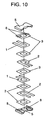
- FIG. 10 is an exploded perspective view of a conventional multilayered thin transformer having no coil base for positioning of coils to be piled up.
- FIG. 11 is a sectional view showing the multilayer structure of the conventional multilayered thin transformer of FIG. 10. Two each of non-wirewound primary coils and secondary coils are produced from a conductor in a thin plate form by such a method as punching or etching.
- a multilayered coil assembly is fabricated by piling insulating paper 3, secondary coil 2, insulating paper 3, primary coil 1, insulating paper 3, secondary coil 2, insulating paper 3, primary coil 1, and insulating paper 3, one on another, as shown in FIG. 10. Then, a suitable amount of adhesive 8, for bonding magnetic core 5 to the multilayered coil, is applied to the top and bottom faces of the multilayered coil. Finally, magnetic cores 5 are mounted in place from above and below and, thereby, a thin transformer is completed. After the completion of the transformer, each coil is connected with a terminal. Each coil is connected to terminal 6 provided on main-unit base 9 via connection portion 7 by such a method as soldering or welding as shown in FIG. 11. In the conventional example shown in FIG. 10, coils are piled up without using a coil base for positioning the coils.
- the present invention aims to solve the above discussed problems in the conventional art examples and to provide a multilayered thin transformer of a coil-baseless type providing stabilized insulating performance and electrical performance and manufactured with high productivity, as well as to provide a method of manufacturing the same.
- the invention provides a thin transformer comprising an insulating paper having either a pressure sensitive adhesive or an adhesive disposed on both faces thereof, a multilayered coil configured by having the insulating paper inserted into at least one place between thin coil layers, and magnetic cores mounted to the multilayered coil from above and below. It further provides a method of manufacturing a thin transformer comprising a first step for preparing thin coils constituting primary coils and secondary coils, a second step for forming a multilayered coil by inserting an insulating paper provided with either a pressure sensitive adhesive or an adhesive disposed on both faces thereof into at least one place between the thin coils, and a final step for mounting magnetic cores to the multilayered coil from above and below.
- FIG. 1 is a sectional view showing a laminated structure of a thin transformer of a first exemplary embodiment of the invention.
- a coil of a non-wirewound type is produced from a thin copper sheet by such a method as punching or etching. Two each of such coils are prepared and they are used as primary coil 11 and secondary coil 12.
- insulating paper 13 provided with pressure sensitive adhesive 18a attached to both sides thereof is stamped into a predetermined shape.
- Insulating paper 13 provided with pressure sensitive adhesive 18a may be a commercially-available pressure sensitive adhesive tape.
- insulating paper 13 may be applied with either pressure sensitive adhesive 18a or adhesive 18 and may thereafter be used. It is preferred that insulating paper 13 be a heat-resistant polyimide film (PI). Other than PI, any of insulating thin film materials may be used for insulating paper 13. Then, as shown in FIG. 1, insulating paper 13 with pressure sensitive adhesive 18a attached thereto, secondary coil 12, insulating paper 13 with pressure sensitive adhesive 18a attached thereto, and primary coil 11 are piled on one another and thus a multilayered coil is formed. Though it is not shown, a laminating jig is used for controlling relative positions between coils and insulating paper 13 in the laminating process.
- PI polyimide film
- the multilayered coil is constructed by inserting insulating paper 13, which has either pressure sensitive adhesive 18a or adhesive 18 disposed on both sides thereof, at least at one place between thin coil layers.
- cores 15 are mounted to the multilayered coil from above and below, occurrence of mutual displacement between the coil and insulating paper 13 can be semipermanently prevented both during the fabrication of the transformer and after its completion. More particularly, variation in the distance between coils piled on one another and the distance between the coil and magnetic core can be suppressed.
- the fabrication method of the first embodiment of the present invention comprises a first step of preparing thin coils constituting the primary coil and the secondary coil, a second step of forming a multilayered coil by inserting insulating paper 13, which is provided with either pressure sensitive adhesive 18a or adhesive 18 disposed on both sides thereof, into at least one place between coil layers, and a final step for mounting magnetic core 15 to the multilayered coil from above and below. Since insulating paper 13 having either pressure sensitive adhesive 18a or adhesive 18 disposed on both surfaces thereof is used in the second step, occurrence of displacement between the laminated coil and insulating paper 13 can be prevented at the time they are put into and out of a tooling jig and at the final step. Thus, a thin multilayered-coil transformer of a coil-base-less type providing stabilized insulating performance and electrical performance and enhanced productivity, as well as a method of manufacturing the same, can be provided.
- PI having a high melting point 400°C or above
- a very high level of safety against the heat produced in the coil can be obtained when it is used for inter-coil insulation.
- High heat resistant insulation withstanding continuous use under F class (155°C) and above can be realized. Accordingly, the transformer size can still be reduced.
- a tape with pressure sensitive adhesive 18a attached thereto is used as insulating paper 13, a step of applying an adhesive and a step for curing it can be omitted in the step of piling up coils and insulating papers 13 and bonding them together.
- primary coil 11 and secondary coil 12 is a thin plate type coil
- magnetic efficiency between the primary and secondary coils is enhanced.
- coils formed from a thin sheet of copper plate are used, cross-sectional areas can be enlarged and hence large currents are allowed to flow therethrough. If, here, at least one of the primary coil and secondary coil is formed on a printed circuit board, the position of the coil conductor and the thickness of the laminated coil can be stabilized and hence variations in performances can be reduced.
- a suitable jig is used for accurately positioning and piling up the coils and insulating papers.
- the first step for preparing thin coils if coils are formed from a copper plate by punching, productivity of coils can be improved and their unit price can be lowered. Further, if the coils are produced from a copper plate by etching, the need for metal dies for punching can be eliminated. It is suited for flexible manufacturing systems because investment can be decreased. Further, burrs are not produced at coil end faces.
- pressure sensitive adhesive 18a is applied to insulating paper 13 in the first embodiment of the invention, adhesive 18, in place of pressure sensitive adhesive 18a, may be applied at the laminating step. Further, instead of preparing insulating papers 13 formed into predetermined shapes, the paper material may be bonded to coils and then may be subjected to punching and, thereafter, they may be laminated.
- FIG. 2 is a sectional view showing a laminated structure of a thin transformer of a second exemplary embodiment of the invention.
- the structure is basically the same as that in the first exemplary embodiment. It greatly differs therefrom in that pressure sensitive adhesive 18a is disposed on both sides of insulating paper 13 on the bottommost layer and topmost layer. By disposing pressure sensitive adhesive 18a on both sides of at least one of insulating papers 13 placed at the bottommost layer and topmost layer, the need for the step for bonding the coil and the core together can be eliminated.
- FIG. 3 is a sectional view showing a laminated structure of a thin transformer of a third exemplary embodiment of the invention.
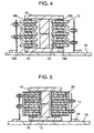
- FIG. 4 is a sectional view showing an adhesive used in the third embodiment of the invention.
- Basic structure shown in FIG. 3 and FIG. 4 is the same as that shown in FIG. 1. It greatly differs from that in the point that adhesive 18b is applied not to the entire surface of insulating paper 13 but to part of the surface. In the manufacturing process, adhesive 18b is applied to part of insulating paper 13, not to the entire surface facing the coil. Material of adhesive 18b used on the bottommost layer and the topmost layer is the same as that of adhesive 18b used between coil layers.
- FIG. 5 is a sectional view showing a laminated structure of a thin transformer of a fourth exemplary embodiment of the invention.
- Insulating resin 20 used in FIG. 5 is a thermoplastic liquid crystal polymer.
- Aromatic polyamide or polyimide resin can be used as the liquid crystal polymer.
- the entire body of the multilayered coil is subjected to injection molding after laminated coils have been formed. Since the entire body of the multilayered coil is sealed up with insulating resin 20, the resin penetrates into spaces between laminated coils.
- insulating resin 20 for the molding is thermoplastic resin, the resin can be recovered for reuse to thereby reduce the material cost. Further, since insulating resin 20 is a high-temperature resisting liquid-crystal polymer, it can stand reflow soldering at the time of surface mounting of the transformer. Further, it is also possible to realize high-temperature resisting insulation enduring continuous use under temperatures of class F (155°C) and above.
- the molding time can be shortened and productivity enhanced. Further, since coils and insulating paper are bonded together, movement of coils by the fluid pressure of the resin during the molding process can be prevented.
- a fifth exemplary embodiment of the invention will be described with reference to FIG. 6 to FIG. 9. Its configuration is basically the same as that of the fourth exemplary embodiment.
- the points in which it greatly differs therefrom are that primary coil 11 is a wirewound coil and that connection portions 17 between primary coil 11a, as well as secondary coil 12, and terminal 16 are covered with resin molding 20.
- primary coil 11a of a wirewound type, secondary coil 12 of a non-wirewound type, and insulating paper 13 with a pressure sensitive adhesive attached thereto are prepared.
- the wire material of primary coil 11a is a round wire coated with an insulating film having a solvent bonding type adhesive layer on the outermost layer.
- Primary coil 11a is manufactured by winding the wire material into the coil on a winding machine provided with a solvent applicator, with the use of a winding jig, while the bonding layer on the wire surface is dissolved by a solvent.
- alcohol is frequently used as the solvent. Examples of the alcohol are ethyl alcohol and isopropyl alcohol.
- primary coil 11a and secondary coil 12 are piled on one another with insulating paper 13, having a pressure sensitive adhesive attached thereto, inserted between the coils to thereby form a multilayered coil.
- connection portions 17 between the coil and the terminal are formed within resin molding 20, insulation between connection portion 17 and the coil can be strengthened.
- coils are formed by winding a wire in the first step of preparing thin coils. Since such processes as etching and punching are not required, a need to change the number of turns can be readily met.
- the first step of preparing a thin coil by winding a wire includes the step of dissolving the adhesive layer on the wire surface with a solvent. Wire winding and bonding can be performed simultaneously only by having the winding machine equipped with a solvent applicator.
- the multilayered coil in the present invention means a coil in which at least one of the primary coil and secondary coil is formed of a thin coil and such thin coils are piled on one another to provide the multilayered coil.
- the present invention provides a multilayered-coil thin transformer of a coil-base-less type stabilized in insulating performance and electrical performance and capable of improving productivity and, also, provides a method of manufacturing the same.
Landscapes
- Engineering & Computer Science (AREA)
- Power Engineering (AREA)
- Insulating Of Coils (AREA)
- Coils Or Transformers For Communication (AREA)
- Coils Of Transformers For General Uses (AREA)
- Manufacturing Cores, Coils, And Magnets (AREA)
Abstract
Description
Claims (25)
- A thin transformer comprising:an insulating paper having one of a pressure sensitive adhesive and an adhesive disposed on both faces thereof;a multilayered coil configured by having said insulating paper inserted into at least one place between thin coil layers; andmagnetic cores mounted to said multilayered coil from above and below.
- The thin transformer according to claim 1, wherein said insulating paper is a polyimide film.
- The thin transformer according to claim 1 or 2, wherein said insulating paper having a pressure sensitive adhesive is a tape having a pressure sensitive adhesive attached thereto.
- The thin transformer according to claim 3, wherein at least one of said insulating papers provided on a bottommost layer and a topmost layer has the pressure sensitive adhesive disposed on both faces thereof.
- The thin transformer according to claim 1 or 2, wherein said insulating paper has the adhesive disposed at a portion of the face of said insulating paper.
- The thin transformer according to claim 5, wherein one of the adhesive and the pressure sensitive adhesive disposed on said insulating paper provided on at least one of a bottommost layer and a topmost layer is identical to one of the adhesive and the pressure sensitive adhesive disposed on said insulating paper used between coils.
- The thin transformer according to any of claims 1 to 6, wherein an entire body of said multilayered coil is sealed in an insulating resin.
- The thin transformer according to claim 7, wherein the insulating resin is a thermoplastic resin.
- The thin transformer according to claim 8, wherein the thermoplastic resin is a liquid crystal polymer.
- The thin transformer according to any of claims 1 to 9, wherein at least one of a primary coil and a secondary coil is a coil in a thin plate form.
- The thin transformer according to claim 10, wherein the coil in a thin plate form is a copper plate.
- The thin transformer according to any of claims 1 to 9, wherein at least one of a primary coil and a secondary coil is a coil formed on a printed circuit board.
- The thin transformer according to any of claims 1 to 9, wherein at least one of a primary coil and a secondary coil is a coil formed by winding an electric wire.
- The thin transformer according to claim 13, wherein the electric wire is one of a round electric wire, a flat-rectangular electric wire, and an electric wire provided with a three-layer insulating coating.
- The thin transformer according to claim 14, wherein the electric wire has a solvent bonding layer.
- The thin transformer according to claim 15, wherein the solvent bonding layer is of an alcohol bonding type.
- The thin transformer according to any of claims 7 to 13, wherein a connection portion between said multilayered coil and a terminal is sealed in a resin molding.
- A method of manufacturing a thin transformer comprising:a first step for preparing thin coils constituting primary coils and secondary coils;a second step for forming a multilayered coil by inserting an insulating paper having one of a pressure sensitive adhesive and an adhesive disposed on both faces thereof into at least one place between the thin coils; anda final step for mounting magnetic cores to the multilayered coil from above and below.
- The method of manufacturing a thin transformer according to claim 18, wherein, in said second step, the adhesive is applied to a portion of an interface between the insulating paper and the multilayered coil.
- The method of manufacturing a thin transformer according to one of claim 18 and claim 19, further comprising a step, between said second step and said final step, of sealing up an entire body of the multilayered coil by injection molding.
- The method of manufacturing a thin transformer according to any of claims 18 to 20, wherein, in said first step, a coil is formed from a copper plate by punching.
- The method of manufacturing a thin transformer according to any of claims 18 to 20, wherein, in said first step, a coil is formed from a copper plate by etching.
- The method of manufacturing a thin transformer according to any of claims 18 to 20, wherein, in said first step, a coil is formed by winding an electric wire.
- The method of manufacturing a thin transformer according to claim 23, wherein said first step includes a step of dissolving a solvent bonding layer on a surface of the electric wire with a solvent.
- The method of manufacturing a thin transformer according to claim 24, wherein the solvent is alcohol.
Applications Claiming Priority (3)
| Application Number | Priority Date | Filing Date | Title |
|---|---|---|---|
| JP2001326245 | 2001-10-24 | ||
| JP2001326245 | 2001-10-24 | ||
| PCT/JP2002/011061 WO2003036665A1 (en) | 2001-10-24 | 2002-10-24 | Low-profile transformer and method of manufacturing the transformer |
Publications (2)
| Publication Number | Publication Date |
|---|---|
| EP1439553A1 true EP1439553A1 (en) | 2004-07-21 |
| EP1439553A4 EP1439553A4 (en) | 2008-12-24 |
Family
ID=19142654
Family Applications (1)
| Application Number | Title | Priority Date | Filing Date |
|---|---|---|---|
| EP02773004A Withdrawn EP1439553A4 (en) | 2001-10-24 | 2002-10-24 | EXTRA-FLAT TRANSFORMER AND METHOD OF MANUFACTURE |
Country Status (5)
| Country | Link |
|---|---|
| US (1) | US6859130B2 (en) |
| EP (1) | EP1439553A4 (en) |
| JP (1) | JPWO2003036665A1 (en) |
| CN (1) | CN100403462C (en) |
| WO (1) | WO2003036665A1 (en) |
Cited By (1)
| Publication number | Priority date | Publication date | Assignee | Title |
|---|---|---|---|---|
| WO2023110839A1 (en) * | 2021-12-17 | 2023-06-22 | Valeo Eautomotive France Sas | Transformer and method for producing such a transformer |
Families Citing this family (61)
| Publication number | Priority date | Publication date | Assignee | Title |
|---|---|---|---|---|
| US7307502B2 (en) * | 2003-07-16 | 2007-12-11 | Marvell World Trade Ltd. | Power inductor with reduced DC current saturation |
| DE102005043972A1 (en) * | 2005-09-15 | 2007-03-29 | Multitorch Gmbh | Method and device for igniting a combustible gas mixture in an internal combustion engine |
| JP4482765B2 (en) * | 2005-09-30 | 2010-06-16 | Tdk株式会社 | Switching power supply |
| TWI264740B (en) * | 2005-12-08 | 2006-10-21 | Delta Electronics Inc | Embedded inductor and manufacturing method thereof |
| US20080061919A1 (en) * | 2006-03-22 | 2008-03-13 | Marek Richard P | Insulators for transformers |
| TWI354302B (en) * | 2006-05-26 | 2011-12-11 | Delta Electronics Inc | Transformer |
| US8427844B2 (en) * | 2006-08-28 | 2013-04-23 | Avago Technologies Ecbu Ip (Singapore) Pte. Ltd. | Widebody coil isolators |
| US20080278275A1 (en) * | 2007-05-10 | 2008-11-13 | Fouquet Julie E | Miniature Transformers Adapted for use in Galvanic Isolators and the Like |
| US7948067B2 (en) * | 2009-06-30 | 2011-05-24 | Avago Technologies Ecbu Ip (Singapore) Pte. Ltd. | Coil transducer isolator packages |
| US9019057B2 (en) * | 2006-08-28 | 2015-04-28 | Avago Technologies General Ip (Singapore) Pte. Ltd. | Galvanic isolators and coil transducers |
| US7791900B2 (en) * | 2006-08-28 | 2010-09-07 | Avago Technologies General Ip (Singapore) Pte. Ltd. | Galvanic isolator |
| US8061017B2 (en) | 2006-08-28 | 2011-11-22 | Avago Technologies Ecbu Ip (Singapore) Pte. Ltd. | Methods of making coil transducers |
| US8093983B2 (en) * | 2006-08-28 | 2012-01-10 | Avago Technologies Ecbu Ip (Singapore) Pte. Ltd. | Narrowbody coil isolator |
| US9105391B2 (en) * | 2006-08-28 | 2015-08-11 | Avago Technologies General Ip (Singapore) Pte. Ltd. | High voltage hold-off coil transducer |
| US8385043B2 (en) * | 2006-08-28 | 2013-02-26 | Avago Technologies ECBU IP (Singapoare) Pte. Ltd. | Galvanic isolator |
| US7791445B2 (en) * | 2006-09-12 | 2010-09-07 | Cooper Technologies Company | Low profile layered coil and cores for magnetic components |
| US8941457B2 (en) * | 2006-09-12 | 2015-01-27 | Cooper Technologies Company | Miniature power inductor and methods of manufacture |
| US8466764B2 (en) | 2006-09-12 | 2013-06-18 | Cooper Technologies Company | Low profile layered coil and cores for magnetic components |
| US8378777B2 (en) * | 2008-07-29 | 2013-02-19 | Cooper Technologies Company | Magnetic electrical device |
| TW200820278A (en) * | 2006-10-16 | 2008-05-01 | Delta Electronics Inc | Transformer |
| JP4845199B2 (en) * | 2006-10-17 | 2011-12-28 | ニチコン株式会社 | Trance |
| TWI333309B (en) * | 2006-11-20 | 2010-11-11 | Unihan Corp | Isolation circuit with good surge and rfi immunity |
| EP1926110B1 (en) * | 2006-11-22 | 2011-06-29 | DET International Holding Limited | Winding assembly and method of its manufacture |
| JP2008270347A (en) * | 2007-04-17 | 2008-11-06 | Densei Lambda Kk | Transformer |
| US20080258855A1 (en) * | 2007-04-18 | 2008-10-23 | Yang S J | Transformer and manufacturing method thereof |
| DE102007019111A1 (en) * | 2007-04-23 | 2008-10-30 | Osram Gesellschaft mit beschränkter Haftung | Electronic component |
| JP4885306B2 (en) * | 2007-04-26 | 2012-02-29 | コーニンクレッカ フィリップス エレクトロニクス エヌ ヴィ | Planar transducer with substrate |
| US7463112B1 (en) | 2007-11-30 | 2008-12-09 | International Business Machines Corporation | Area efficient, differential T-coil impedance-matching circuit for high speed communications applications |
| CN101681907B (en) * | 2007-11-30 | 2012-11-07 | 松下电器产业株式会社 | Heat dissipating structure base board, module using heat dissipating structure base board, and method for manufacturing heat dissipating structure base board |
| US8258911B2 (en) | 2008-03-31 | 2012-09-04 | Avago Technologies ECBU IP (Singapor) Pte. Ltd. | Compact power transformer components, devices, systems and methods |
| JP5088310B2 (en) * | 2008-12-11 | 2012-12-05 | サンケン電気株式会社 | Electronic circuit equipment |
| US20100237976A1 (en) * | 2009-03-17 | 2010-09-23 | Li Chiu K | Low-profile inductive coil and methond of manufacture |
| JP4821870B2 (en) | 2009-03-19 | 2011-11-24 | Tdk株式会社 | Coil component, transformer, switching power supply device, and method of manufacturing coil component |
| TWM364957U (en) * | 2009-04-17 | 2009-09-11 | Delta Electronics Inc | Winding structure for a transformer and winding |
| US20140211360A1 (en) * | 2009-06-02 | 2014-07-31 | Correlated Magnetics Research, Llc | System and method for producing magnetic structures |
| US20140111296A1 (en) * | 2012-10-24 | 2014-04-24 | Correlated Magnetics Research, Llc | System and method for producing magnetic structures |
| US7830237B1 (en) * | 2009-08-19 | 2010-11-09 | Intelextron Inc. | Transformer |
| JP5413445B2 (en) * | 2011-03-29 | 2014-02-12 | 株式会社デンソー | Trance |
| KR101251842B1 (en) * | 2011-12-19 | 2013-04-09 | 엘지이노텍 주식회사 | Transformer |
| DE102012003365B4 (en) * | 2012-02-22 | 2014-12-18 | Phoenix Contact Gmbh & Co. Kg | Planar intrinsically safe transformer with layer structure |
| US8980053B2 (en) | 2012-03-30 | 2015-03-17 | Sabic Innovative Plastics Ip B.V. | Transformer paper and other non-conductive transformer components |
| CN105099132B (en) * | 2014-04-30 | 2018-08-31 | 台达电子工业股份有限公司 | Electronic device |
| TWI475579B (en) * | 2012-12-14 | 2015-03-01 | Ghing Hsin Dien | Coil |
| JP6138540B2 (en) * | 2013-03-27 | 2017-05-31 | 日本電気通信システム株式会社 | Transformer and manufacturing method thereof |
| US20140347154A1 (en) * | 2013-05-21 | 2014-11-27 | Coherent, Inc. | Interleaved planar pcb rf transformer |
| JP6120009B2 (en) * | 2014-04-10 | 2017-04-26 | 株式会社豊田自動織機 | Induction equipment |
| US9711276B2 (en) * | 2014-10-03 | 2017-07-18 | Instrument Manufacturing Company | Resonant transformer |
| US9672974B2 (en) * | 2014-11-20 | 2017-06-06 | Panasonic Intellectual Property Management Co., Ltd. | Magnetic component and power transfer device |
| US20160225514A1 (en) * | 2015-02-04 | 2016-08-04 | Astec International Limited | Power transformers and methods of manufacturing transformers and windings |
| CN106158286B (en) * | 2015-04-27 | 2018-04-10 | 台达电子工业股份有限公司 | Transformer with center tap |
| JP2017069460A (en) * | 2015-09-30 | 2017-04-06 | 太陽誘電株式会社 | Coil component and manufacturing method therefor |
| US10404178B2 (en) * | 2016-04-21 | 2019-09-03 | Mitsubishi Electric Corporation | Insulation type step-up converter |
| CN106158288B (en) * | 2016-06-22 | 2019-12-06 | 西北核技术研究所 | Copper-titanium composite Tesla transformer primary coil |
| WO2018043429A1 (en) * | 2016-09-01 | 2018-03-08 | 三菱電機株式会社 | Method for manufacturing laminate core, and armature using laminate core |
| US11239019B2 (en) | 2017-03-23 | 2022-02-01 | Tdk Corporation | Coil component and method of manufacturing coil component |
| EP3631822A4 (en) * | 2017-05-29 | 2021-03-10 | Thin Energy Ltd. | Thin transformer and method of production of same |
| CN107424798A (en) * | 2017-08-22 | 2017-12-01 | 王勇 | A kind of insulating method of super strip conductor coil |
| CN208622565U (en) * | 2018-07-18 | 2019-03-19 | 台达电子工业股份有限公司 | Magnetic element module |
| JP7198129B2 (en) * | 2019-03-22 | 2022-12-28 | 日本電産モビリティ株式会社 | Coil parts, electronic devices |
| US20220310302A1 (en) * | 2021-03-29 | 2022-09-29 | Texas Instruments Incorporated | Integrated magnetic core and winding lamina |
| WO2025247898A1 (en) * | 2024-05-28 | 2025-12-04 | Aalborg Universitet | A method and a system for manufacturing a planar winding assembly for power applications |
Family Cites Families (29)
| Publication number | Priority date | Publication date | Assignee | Title |
|---|---|---|---|---|
| JPH04504643A (en) * | 1989-12-12 | 1992-08-13 | ザ スペリオール エレクトリック カンパニー | electrical equipment |
| DE4023141A1 (en) * | 1990-07-20 | 1992-01-30 | Siemens Matsushita Components | Encapsulating prismatic inductance - has fixing contact ends in off=centre split plane of mould and injecting resin asymmetrically to inductance |
| JPH04145610A (en) * | 1990-10-08 | 1992-05-19 | Fukushima Tokai Denshi Kogyo Kk | Manufacture of rotary transformer |
| JPH0531213A (en) | 1991-01-07 | 1993-02-09 | Oshima Kensetsu Kk | Energy utilization type training device |
| JPH0513027A (en) | 1991-07-02 | 1993-01-22 | Nec Corp | Noctovision |
| JPH0513027U (en) * | 1991-07-26 | 1993-02-19 | 株式会社タムラ製作所 | Sheet coil for transformer |
| JPH0531213U (en) * | 1991-09-27 | 1993-04-23 | テイーデイーケイ株式会社 | Trance |
| JPH0722252A (en) * | 1993-06-30 | 1995-01-24 | Tokin Corp | Multilayer inductor |
| JPH0737436A (en) * | 1993-07-26 | 1995-02-07 | Optec Dai Ichi Denko Co Ltd | Self-fusable insulated electric cable |
| JPH07240324A (en) * | 1994-02-28 | 1995-09-12 | Kijima Musen Kk | Small-sized transformer |
| JPH07326525A (en) * | 1994-05-31 | 1995-12-12 | Sumitomo 3M Ltd | Insulating adhesive tape and transformer using the same |
| US6000128A (en) * | 1994-06-21 | 1999-12-14 | Sumitomo Special Metals Co., Ltd. | Process of producing a multi-layered printed-coil substrate |
| JPH08148348A (en) * | 1994-11-25 | 1996-06-07 | Nissin Electric Co Ltd | Voltage transformer |
| JP3152088B2 (en) * | 1994-11-28 | 2001-04-03 | 株式会社村田製作所 | Manufacturing method of coil parts |
| JP2793150B2 (en) * | 1995-07-25 | 1998-09-03 | 関西電力株式会社 | Elevator |
| JPH09219324A (en) * | 1996-02-13 | 1997-08-19 | Shindengen Electric Mfg Co Ltd | Wire wheel component and manufacturing method thereof |
| US6356181B1 (en) * | 1996-03-29 | 2002-03-12 | Murata Manufacturing Co., Ltd. | Laminated common-mode choke coil |
| US5781093A (en) * | 1996-08-05 | 1998-07-14 | International Power Devices, Inc. | Planar transformer |
| JPH10163039A (en) * | 1996-12-05 | 1998-06-19 | Tdk Corp | Thin transformer |
| JPH10340819A (en) * | 1997-06-05 | 1998-12-22 | Tokin Corp | Coil and thin transformer |
| JP3615024B2 (en) * | 1997-08-04 | 2005-01-26 | 株式会社村田製作所 | Coil parts |
| JP3381573B2 (en) * | 1997-09-25 | 2003-03-04 | 松下電器産業株式会社 | Thin coil parts |
| JPH11144965A (en) * | 1997-11-12 | 1999-05-28 | Tokin Corp | Electronic component manufacturing method |
| JP2000306750A (en) * | 1999-04-21 | 2000-11-02 | Tokin Corp | choke coil |
| JP2000308750A (en) | 1999-04-28 | 2000-11-07 | Sankyo Kk | Game device |
| JP2001284130A (en) * | 2000-03-29 | 2001-10-12 | Densei Lambda Kk | Inductance device |
| JP2001323245A (en) * | 2000-05-15 | 2001-11-22 | Murata Mfg Co Ltd | Adhesive resin composition, method for producing adhesive resin composition and chip-formed coil part |
| JP3724405B2 (en) * | 2001-10-23 | 2005-12-07 | 株式会社村田製作所 | Common mode choke coil |
| JP2003347125A (en) * | 2002-05-27 | 2003-12-05 | Sansha Electric Mfg Co Ltd | coil |
-
2002
- 2002-10-24 EP EP02773004A patent/EP1439553A4/en not_active Withdrawn
- 2002-10-24 JP JP2003539062A patent/JPWO2003036665A1/en active Pending
- 2002-10-24 US US10/466,956 patent/US6859130B2/en not_active Expired - Fee Related
- 2002-10-24 CN CNB028048628A patent/CN100403462C/en not_active Expired - Fee Related
- 2002-10-24 WO PCT/JP2002/011061 patent/WO2003036665A1/en not_active Ceased
Cited By (2)
| Publication number | Priority date | Publication date | Assignee | Title |
|---|---|---|---|---|
| WO2023110839A1 (en) * | 2021-12-17 | 2023-06-22 | Valeo Eautomotive France Sas | Transformer and method for producing such a transformer |
| FR3131070A1 (en) * | 2021-12-17 | 2023-06-23 | Valeo Siemens Eautomotive France Sas | TRANSFORMER AND METHOD FOR MANUFACTURING SUCH A TRANSFORMER |
Also Published As
| Publication number | Publication date |
|---|---|
| US20040070480A1 (en) | 2004-04-15 |
| WO2003036665A1 (en) | 2003-05-01 |
| JPWO2003036665A1 (en) | 2005-02-17 |
| US6859130B2 (en) | 2005-02-22 |
| EP1439553A4 (en) | 2008-12-24 |
| CN1491423A (en) | 2004-04-21 |
| CN100403462C (en) | 2008-07-16 |
Similar Documents
| Publication | Publication Date | Title |
|---|---|---|
| US6859130B2 (en) | Low-profile transformer and method of manufacturing the transformer | |
| US12568586B2 (en) | Inductor assembly and manufacturing method for inductor assembly | |
| US8910373B2 (en) | Method of manufacturing an electromagnetic component | |
| GB2260222A (en) | Flat coils | |
| JP7369546B2 (en) | coil parts | |
| US11610726B2 (en) | Coil device and pulse transformer | |
| KR20070082539A (en) | Core Structure with Gap for Magnetic Components | |
| JP3551135B2 (en) | Thin transformer and method of manufacturing the same | |
| US20170027061A1 (en) | Multi-layer wiring structure, magnetic element and manufacturing method thereof | |
| JP2012038941A (en) | Transformer | |
| CN110415945A (en) | Transformer and its manufacturing method and electromagnetic device | |
| JP3489553B2 (en) | Thin transformer | |
| CN110415944B (en) | Transformer, manufacturing method thereof and electromagnetic device | |
| US9440378B2 (en) | Planar electronic device and method for manufacturing | |
| CN106376173B (en) | Multilayer lead structure of printed circuit board, magnetic element and manufacturing method thereof | |
| CN110415940B (en) | Integrated transformer and electronic device | |
| CN116153638A (en) | A kind of manufacturing method of planar transformer and planar transformer | |
| JP2004303746A (en) | Thin transformer | |
| KR102558332B1 (en) | Inductor and producing method of the same | |
| JP3707461B2 (en) | Coil parts manufacturing method | |
| JP2002064017A (en) | Thin transformer and method of manufacturing the same | |
| KR20210089305A (en) | A planar transformer | |
| JP3570358B2 (en) | Thin mold transformer | |
| CN110415946B (en) | Electromagnetic element and method for manufacturing the same | |
| JP3290510B2 (en) | Laminated mold coil and method of manufacturing the same |
Legal Events
| Date | Code | Title | Description |
|---|---|---|---|
| PUAI | Public reference made under article 153(3) epc to a published international application that has entered the european phase |
Free format text: ORIGINAL CODE: 0009012 |
|
| 17P | Request for examination filed |
Effective date: 20040206 |
|
| AK | Designated contracting states |
Kind code of ref document: A1 Designated state(s): AT BE BG CH CY CZ DE DK EE ES FI FR GB GR IE IT LI LU MC NL PT SE SK TR |
|
| RIN1 | Information on inventor provided before grant (corrected) |
Inventor name: SUZUKI, TSUKASA Inventor name: HASHIMOTO, FUMIAKI Inventor name: INABA, SATORU Inventor name: MARUI, TOMIO Inventor name: HASHIMOTO, NAOKI Inventor name: NAKASHIMA, KOJI Inventor name: TANIGUCHI, SATORU |
|
| RAP1 | Party data changed (applicant data changed or rights of an application transferred) |
Owner name: PANASONIC CORPORATION |
|
| A4 | Supplementary search report drawn up and despatched |
Effective date: 20081126 |
|
| 17Q | First examination report despatched |
Effective date: 20090525 |
|
| STAA | Information on the status of an ep patent application or granted ep patent |
Free format text: STATUS: THE APPLICATION IS DEEMED TO BE WITHDRAWN |
|
| 18D | Application deemed to be withdrawn |
Effective date: 20120327 |