EP1439441A2 - Verfahren zur Kennzeichnung und Management von Fehlern und Defekten in Montage- und Schweisslinien für Kraftfahrzeugkarosserien, Karosserieteilen oder dergleichen und Anlage nach diesem Verfahren - Google Patents
Verfahren zur Kennzeichnung und Management von Fehlern und Defekten in Montage- und Schweisslinien für Kraftfahrzeugkarosserien, Karosserieteilen oder dergleichen und Anlage nach diesem Verfahren Download PDFInfo
- Publication number
- EP1439441A2 EP1439441A2 EP03021929A EP03021929A EP1439441A2 EP 1439441 A2 EP1439441 A2 EP 1439441A2 EP 03021929 A EP03021929 A EP 03021929A EP 03021929 A EP03021929 A EP 03021929A EP 1439441 A2 EP1439441 A2 EP 1439441A2
- Authority
- EP
- European Patent Office
- Prior art keywords
- parts
- points
- stations
- measurement
- stresses
- Prior art date
- Legal status (The legal status is an assumption and is not a legal conclusion. Google has not performed a legal analysis and makes no representation as to the accuracy of the status listed.)
- Withdrawn
Links
- 238000000034 method Methods 0.000 title claims abstract description 86
- 230000007547 defect Effects 0.000 title claims description 17
- 238000003466 welding Methods 0.000 title description 20
- 238000005259 measurement Methods 0.000 claims abstract description 61
- 230000008569 process Effects 0.000 claims abstract description 49
- 238000012545 processing Methods 0.000 claims abstract description 21
- 238000003745 diagnosis Methods 0.000 claims abstract description 12
- 238000004458 analytical method Methods 0.000 claims abstract description 6
- 230000008030 elimination Effects 0.000 claims abstract description 4
- 238000003379 elimination reaction Methods 0.000 claims abstract description 4
- 238000013178 mathematical model Methods 0.000 claims abstract description 3
- 230000000903 blocking effect Effects 0.000 claims description 29
- 238000012937 correction Methods 0.000 claims description 17
- 238000002560 therapeutic procedure Methods 0.000 claims description 14
- 238000009826 distribution Methods 0.000 claims description 8
- 238000012417 linear regression Methods 0.000 claims description 8
- 238000012916 structural analysis Methods 0.000 claims description 8
- 230000008859 change Effects 0.000 claims description 5
- 238000013459 approach Methods 0.000 claims description 3
- 230000035945 sensitivity Effects 0.000 claims description 3
- 230000011664 signaling Effects 0.000 claims description 3
- 230000009897 systematic effect Effects 0.000 claims description 3
- 241000196324 Embryophyta Species 0.000 claims 6
- 240000002024 Gossypium herbaceum Species 0.000 claims 1
- 230000035882 stress Effects 0.000 description 16
- 230000006870 function Effects 0.000 description 14
- 230000000694 effects Effects 0.000 description 12
- 230000009471 action Effects 0.000 description 11
- 238000004519 manufacturing process Methods 0.000 description 7
- 239000002184 metal Substances 0.000 description 7
- 238000007726 management method Methods 0.000 description 4
- 239000011159 matrix material Substances 0.000 description 4
- 230000001427 coherent effect Effects 0.000 description 3
- 230000002596 correlated effect Effects 0.000 description 3
- 230000008878 coupling Effects 0.000 description 3
- 238000010168 coupling process Methods 0.000 description 3
- 238000005859 coupling reaction Methods 0.000 description 3
- 230000002950 deficient Effects 0.000 description 3
- 238000003825 pressing Methods 0.000 description 3
- 230000009467 reduction Effects 0.000 description 3
- 238000004026 adhesive bonding Methods 0.000 description 2
- 230000008901 benefit Effects 0.000 description 2
- 238000004364 calculation method Methods 0.000 description 2
- 230000001447 compensatory effect Effects 0.000 description 2
- 238000009109 curative therapy Methods 0.000 description 2
- 238000012423 maintenance Methods 0.000 description 2
- 238000005457 optimization Methods 0.000 description 2
- 238000004393 prognosis Methods 0.000 description 2
- 238000005070 sampling Methods 0.000 description 2
- 230000009466 transformation Effects 0.000 description 2
- 230000002547 anomalous effect Effects 0.000 description 1
- 230000000712 assembly Effects 0.000 description 1
- 238000000429 assembly Methods 0.000 description 1
- 238000012550 audit Methods 0.000 description 1
- 230000015572 biosynthetic process Effects 0.000 description 1
- 238000007796 conventional method Methods 0.000 description 1
- 238000000354 decomposition reaction Methods 0.000 description 1
- 230000000593 degrading effect Effects 0.000 description 1
- 238000001514 detection method Methods 0.000 description 1
- 230000004069 differentiation Effects 0.000 description 1
- 238000006073 displacement reaction Methods 0.000 description 1
- 238000011156 evaluation Methods 0.000 description 1
- 230000006872 improvement Effects 0.000 description 1
- 239000000463 material Substances 0.000 description 1
- 238000004021 metal welding Methods 0.000 description 1
- 238000012544 monitoring process Methods 0.000 description 1
- 230000007170 pathology Effects 0.000 description 1
- 238000003908 quality control method Methods 0.000 description 1
- 238000004826 seaming Methods 0.000 description 1
- 238000009958 sewing Methods 0.000 description 1
- 238000004088 simulation Methods 0.000 description 1
- 230000006641 stabilisation Effects 0.000 description 1
- 238000011105 stabilization Methods 0.000 description 1
- 238000007619 statistical method Methods 0.000 description 1
- 238000003786 synthesis reaction Methods 0.000 description 1
- 230000008646 thermal stress Effects 0.000 description 1
- 239000002699 waste material Substances 0.000 description 1
Images
Classifications
-
- B—PERFORMING OPERATIONS; TRANSPORTING
- B62—LAND VEHICLES FOR TRAVELLING OTHERWISE THAN ON RAILS
- B62D—MOTOR VEHICLES; TRAILERS
- B62D65/00—Designing, manufacturing, e.g. assembling, facilitating disassembly, or structurally modifying motor vehicles or trailers, not otherwise provided for
- B62D65/005—Inspection and final control devices
-
- B—PERFORMING OPERATIONS; TRANSPORTING
- B23—MACHINE TOOLS; METAL-WORKING NOT OTHERWISE PROVIDED FOR
- B23K—SOLDERING OR UNSOLDERING; WELDING; CLADDING OR PLATING BY SOLDERING OR WELDING; CUTTING BY APPLYING HEAT LOCALLY, e.g. FLAME CUTTING; WORKING BY LASER BEAM
- B23K26/00—Working by laser beam, e.g. welding, cutting or boring
- B23K26/02—Positioning or observing the workpiece, e.g. with respect to the point of impact; Aligning, aiming or focusing the laser beam
- B23K26/03—Observing, e.g. monitoring, the workpiece
-
- Y—GENERAL TAGGING OF NEW TECHNOLOGICAL DEVELOPMENTS; GENERAL TAGGING OF CROSS-SECTIONAL TECHNOLOGIES SPANNING OVER SEVERAL SECTIONS OF THE IPC; TECHNICAL SUBJECTS COVERED BY FORMER USPC CROSS-REFERENCE ART COLLECTIONS [XRACs] AND DIGESTS
- Y02—TECHNOLOGIES OR APPLICATIONS FOR MITIGATION OR ADAPTATION AGAINST CLIMATE CHANGE
- Y02P—CLIMATE CHANGE MITIGATION TECHNOLOGIES IN THE PRODUCTION OR PROCESSING OF GOODS
- Y02P90/00—Enabling technologies with a potential contribution to greenhouse gas [GHG] emissions mitigation
- Y02P90/02—Total factory control, e.g. smart factories, flexible manufacturing systems [FMS] or integrated manufacturing systems [IMS]
-
- Y—GENERAL TAGGING OF NEW TECHNOLOGICAL DEVELOPMENTS; GENERAL TAGGING OF CROSS-SECTIONAL TECHNOLOGIES SPANNING OVER SEVERAL SECTIONS OF THE IPC; TECHNICAL SUBJECTS COVERED BY FORMER USPC CROSS-REFERENCE ART COLLECTIONS [XRACs] AND DIGESTS
- Y10—TECHNICAL SUBJECTS COVERED BY FORMER USPC
- Y10T—TECHNICAL SUBJECTS COVERED BY FORMER US CLASSIFICATION
- Y10T29/00—Metal working
- Y10T29/49—Method of mechanical manufacture
- Y10T29/49764—Method of mechanical manufacture with testing or indicating
- Y10T29/49771—Quantitative measuring or gauging
- Y10T29/49776—Pressure, force, or weight determining
Definitions
- the present invention relates to a method for identification and management of errors and defects in assembly and welding lines for automotive vehicle bodies and body parts or the like.
- the management concerns diagnosis and if necessary therapy of defects.
- the present invention also relates to a plant in accordance with said method.
- Degrading factors can be for example peculiar to the assembly technique used or due to geometrical changes occurring after the initial setting of one or more stations. For example, with assembly by welding, variations or drifting of the welding parameters such as those due to the consumption of the electrode, variation of the electrical current or welding time, change in position or sequence of performance of the welding points et cetera can occur. Similar factors can also be traced for the other assembly methods.
- Geometrical variations can also be caused by maintenance work and/or adjustment of the stations, wear of movement parts or even variation of physical parameters of the parts being assembled (changes of composition, thickness, shape et cetera of the parts to be assembled). Typical is change of the thickness of parts pressed from sheet metal with change of the production lot.
- sampling is usually done in the prior art by taking at intervals an article at the end of the line and inspecting it in special measuring stations to find the deviations from the "ideal" shape. If defects beyond the tolerable limits are found the line or part thereof is stopped and it is sought to trace back to the station or stations which produced the defect to then trace the cause of the defect within the station or stations thus identified. Lastly, the necessary corrective action is taken.
- the general purpose of the present invention is to remedy the above mentioned shortcomings by making available a method and plant allowing efficient identification of errors, going back rapidly to the specific causes and, if necessary, information useful for their rapid and practical resolution.
- a plant made up of a plurality of automated stations for the performance of an assembly process for body parts or the like with there being in the stations automatic means for support and blocking of the parts to be assembled and automatic assembly means for the supported and blocked parts and a method for identification and management of errors and defects
- method comprises steps of preliminary analysis with the steps of determining measurement points sensitive to the movements of constraint points which comprise support and blocking points for the parts in the stations, determining correlations between measurements detectable in said measurement points sensitive to said movements, and possible causes which might generate such movements, and inline diagnostic steps comprising the steps of overseeing any movements in the previously ascertained measurement points and in this case going back to the possible causes of the movements and signaling such possible causes to allow their elimination if desired or necessary.
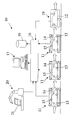
- a plant realized in accordance with the present invention and designated as a whole by reference number 10 is shown diagrammatically.
- the plant there is a plurality of stations 11 each of which performs specific steps of a process for the realization of an assembled part or body 12 of an automotive vehicle.
- the various steps can be welding, riveting, gluing et cetera of body parts to achieve the desired product.
- the structure and assembly means of the various stations are not further shown as they are known and readily imaginable to those skilled in the art.
- Each station comprises known blocking inserts 13 for mutual positioning of the parts to be assembled and known assembly devices 14 (for example welding robots) which fasten the various body parts permanently.
- each station there is a plurality of sensors 15 which detect (in accordance with the description below) the position of points of the body parts in the station.
- the measurements taken in the stations are all gathered in a processing system or unit 16 which processes the data and displays them on a terminal 17 in addition to memorizing them in an orderly manner in a data bank 18.
- a known measurement station 19 for detecting a certain number of dimensional parameters on the article.
- the actual diagnosis consists of ascertaining the point of the production process in which lies the cause of an anomaly ("location of the anomaly along the process"). Locating is both at the processing station level (for example “the cause acts in the geometry station of body no. 120") and in the processing step (for example “the cause acts in the welding step”). The point on the part in which the anomaly acts ("locating the anomaly along the part") must also be identified.
- Locating tends to put the part in relation with the equipment (for example “the cause lies in nearness of the inserts 25 and 26") or with other parts to which it couples (for example “the cause lies along the coupling surface of the side with the floor”).
- the nature of the cause which generated the anomaly (definition of the nature of the anomaly or pathology) must be identified.
- Locating the cause along the process can be made complicated by the fact that in some cases, due to the error multiplication factor the phenomenon appears clearly only much further down stream from the point where it was generated. For example, certain processing errors of the floor can appear only when coupling with the sides in the body geometry stations is performed.
- Locating the cause along the part can present similar problems. In this case it is necessary to differentiate the point where the cause lies in relation to the points which suffer only from the effects of said cause. This is true in particular when the anomaly appears in different points of the part but depends on a single cause. Similarly to the above case, the errors can be more obvious at points far from the cause than in close points. For example, floor errors, hence in the lower part of the body, can be made more obvious on the roof and hence in the higher part of the body due to a "lever" effect produced by the resulting errors of positioning of the body sides.
- a preliminary step is advantageously performed comprising identification of the measurement points sensitive to movements of support and blocking points in the various stations and sensitive to possible causes of simulatable movement and the creation of a simplified matrix constructed on the constraint and measurement points with very fast resolution and hence suitable for performing inline search operations by trial and error. The correlations between movement detected and possible causes which generated them can thus be ascertained.
- the first step in creation of a simplified matrix for inline search operations by trial and error takes place by utilizing known structural analysis concepts.
- the mathematical structural model of the parts being processed is done by using conventional techniques and thus obtaining what might be defined "a complete structural model". From the complete model is then taken a "simplified structural model" in which the nodes are reduced at the points of constraint and stress application (for example, the references and blocking inserts in the stations) and at the reading points of the measurement sensors just of the processing stations. With known techniques this simplified model can be advantageously reduced further to obtain a very simple matrix calculable with high rapidity.
- the trial and error solution method is used for diagnostic operations in which, given a certain distribution of real deformations detected, the point of stress which generates it and the extent of said stress are taken, and for correction (or "therapy") operations in which, given a certain distribution of real deformations detected, the distribution of the stresses which might be applied to compensate for said deformations is obtained.
- the points at which the deformations are detected must be chosen so as to optimize the definition of the constraint or stress points (for example the inserts) which generate the deformations either for diagnosis operations or therapy operations.
- the structural model of the part is used to determine the "zones" (defined by a series of points) of sensitivity for each simulatable cause of stress (for example the position of the inserts) and possible combinations thereof.
- the "zones" thus defined are then differentiated in relation to the causes associated with them and the "trial and error” method is applied to the differentiated zones in order to define the optimal measurement points.
- This procedure consists of positioning the sensors virtually in the "zones" previously differentiated and calculating the number of causes detectable.
- the optimal solution constituted by the complex of sensors which ensures maximization of the number of causes detectable and minimization of the number of sensors used can be defined.
- results thus obtained are then used to define the simulated causes which can be differentiated (normally all) and the correlations between chosen "zones" and causes, understood as bijective association between combinations of measured values, expressed as all or nothing (1 or 0) with respect to certain thresholds, and relative cause.
- the system can indicate the differentiatable causes accompanied by all the parameters mentioned above and also indicate the undifferentiatable causes accompanied by the respective signatures.
- nonlinear operations must intervene in the production cycle which takes place between blocking and unblocking of the part.
- the nonlinear operations consist of relative movements (running and striking movements) of the sheet metal of the parts to be assembled upon blocking which are subsequently “frozen” by the welding operations. If these relative movements are influenced by the position of the blockings, movement of the relative inserts results in permanent corrections.
- sensitive points are defined here "sensitive points”.
- the problem is to determine these sensitive points.
- the present invention also sets out to determine the "sensitive points" of a certain welding process on the basis of statistical processing without requiring physical movement of the blockings, normally a delicate and costly operation. To determine these points which are based here on the consideration that due to the effect of dispersal of the shapes and positions of the parts coming in there are many combinations between geometry of the part and geometry of the inserts usable at the statistic level.
- the metrology i.e. the dimensional characteristics measurement and reading systems which it is desired to watch
- the process is distributed along the process (advantageously fitted directly in the equipment of the various stations so as to be able to measure during all the welding operations also without requiring dedicated space) and concentrated at line end (for example realized with measurement machines with coordinates of the DEA type).
- references can be affected by errors (also subject to diagnosis) and because during measurement the part can be supported not on its reference points but on other points known with slight precision as happens, for example, when it is seized by handling members.
- the first case is that in which the part is held isostatically. In this case the variations are due only to different effects of the weight forces and the solution is analogous to that of the preceding case.
- the second case is that in which the part is held and blocked hyperstatically.
- allowance must be made for deformations induced by the blocking.
- a first example of the use of correlated metrological data coming from different reading systems is that of the so-called "process signature".
- the metrology distributed along the process which generates a signaling where the anomaly starts to appear provides for this.
- the anomaly does not always appear simply as a deviation from zero error. Indeed, normally in processes such as those of automobile sheet metal work, to obtain zero error on the finished product it is normal to have certain deviations from zero in certain points of the process and of the part which are subsequently compensated for and nullified.
- process signature the signature is characteristic for each plant
- zero signature the process signature which leads to having zero errors on the final part. This is never completely “flat” even if this situation constitutes the intended objective since it is one of the conditions of the ideal "zero tension” process.
- the zero signature is all equal to zero ("flat zero signature") only in the extreme case of "zero tension process" which constitutes an ideal situation never completely realizable but which it is well to prepare.
- the "zero signature” is obtained by correlation between data measured along the line ("distributed metrology") and data measured at line end ("certification or audit concentrated metrology”). Obtaining the signature is a typically statistical operation calculated on the systematic values. The actual signature is then taken inline and its deviations from the zero signature are used to ascertain the process points having anomalous behavior (anomaly location).
- a second example of use of correlated metrological data coming from different reading systems is that of decomposition and recomposition of the figures in the operations of distinguishing of the position and shape errors.
- one of the important objectives of the diagnosis is to distinguish the causes of anomalies which translate into local shape errors - for example generated upon pressing the sheet metal - and the causes of anomalies which translate into mutual position errors of assembled parts, for example generated by incorrect welding operations.
- the real geometry of the part is reconstructed here by "sewing" the data which describe the local errors of shape to the data describing the general geometry deriving from the manner of connecting the parts. To do this, the following method in three steps is followed advantageously.
- the local shape data are read, if necessary focusing on critical measurement zones the measurements made with flexible reading systems 20, for example with coordinate measurement machines or anthropomorphous measurement robots.
- the measurements are made on parts 21 which constitute subassemblies of the parts which are realized by the assembly of parts 21 until the product or final part 12 is realized.
- the general data of the coupling geometry of the parts are read with inline machines with very high sampling, for example with known parallel measurement systems which comprise or are the sensor systems 15 of the stations.
- the data are sent to the processing unit 16 and the general geometry reconstruction is done by the latter by known structural analysis using as starting geometrical data the local shape error data taken in the first step and as constraints the part positioning data taken in the second step.
- the first step of the therapy continues with identification of the movements of the inserts, i.e. with identification of the inserts to be moved and the amount of the movement as a function of preset final precision objectives.
- two different therapy strategies can be applied which can be indicated as curative therapy, i.e. therapies which tend to remove the cause of the defect, and compensative therapies, i.e. therapies which tend to compensate for the effect even without knowing the cause of the defect when it is not possible or appropriate to take action where the cause arises (for example compensation in the assembly station of shape errors of the parts due to pressing).
- the system In application of a curative therapy the system identifies the "out of place” insert and indicates the correction to be made on it.
- the system (for example after the operator has indicated the maximum residual error it is wished to obtain) identifies the minimum number of inserts to be moved and chooses the inserts on which to act so as to obtain the result with the minimum movement, indicates the movements to be made and lastly indicates the residual errors after the correction.
Landscapes
- Engineering & Computer Science (AREA)
- Mechanical Engineering (AREA)
- Physics & Mathematics (AREA)
- Optics & Photonics (AREA)
- Manufacturing & Machinery (AREA)
- Chemical & Material Sciences (AREA)
- Combustion & Propulsion (AREA)
- Transportation (AREA)
- Plasma & Fusion (AREA)
- Testing Of Devices, Machine Parts, Or Other Structures Thereof (AREA)
- Automatic Assembly (AREA)
- General Factory Administration (AREA)
Applications Claiming Priority (2)
| Application Number | Priority Date | Filing Date | Title |
|---|---|---|---|
| IT002109A ITMI20022109A1 (it) | 2002-10-04 | 2002-10-04 | Metodo per l'individuazione e la gestione di errori e |
| ITMI20022109 | 2002-10-04 |
Publications (1)
| Publication Number | Publication Date |
|---|---|
| EP1439441A2 true EP1439441A2 (de) | 2004-07-21 |
Family
ID=32040261
Family Applications (1)
| Application Number | Title | Priority Date | Filing Date |
|---|---|---|---|
| EP03021929A Withdrawn EP1439441A2 (de) | 2002-10-04 | 2003-09-29 | Verfahren zur Kennzeichnung und Management von Fehlern und Defekten in Montage- und Schweisslinien für Kraftfahrzeugkarosserien, Karosserieteilen oder dergleichen und Anlage nach diesem Verfahren |
Country Status (4)
| Country | Link |
|---|---|
| US (1) | US6898553B2 (de) |
| EP (1) | EP1439441A2 (de) |
| JP (1) | JP2004127304A (de) |
| IT (1) | ITMI20022109A1 (de) |
Families Citing this family (16)
| Publication number | Priority date | Publication date | Assignee | Title |
|---|---|---|---|---|
| JP4418818B2 (ja) * | 2004-03-29 | 2010-02-24 | 財団法人大阪産業振興機構 | 溶接変形算出装置、及びコンピュータプログラム |
| AT502326B1 (de) * | 2005-09-09 | 2009-07-15 | Fronius Int Gmbh | Fernzugriffseinheit und kommunikationsverfahren zur verwaltung von schweissgeräten |
| US7266468B1 (en) | 2006-03-03 | 2007-09-04 | Perceptron, Inc. | Structural data analysis system |
| KR100776486B1 (ko) * | 2006-04-19 | 2007-11-16 | 주식회사 텔사인 | 무선인식기와 조립공구를 이용한 자동차 조립 공정 방법 |
| US7546493B2 (en) * | 2006-04-28 | 2009-06-09 | Siemens Aktiengesellschaft | Method for responding to errors occurring during operation of a networked medical system |
| US20080016119A1 (en) * | 2006-07-14 | 2008-01-17 | Sharma Parit K | Quality Assurance System and Method |
| BRPI0722148A2 (pt) * | 2007-11-29 | 2014-04-15 | Airbus Operations Gmbh | Sistema de diagnóstico |
| JP5200970B2 (ja) * | 2009-02-04 | 2013-06-05 | 富士ゼロックス株式会社 | 品質管理システムおよび品質管理装置および品質管理プログラム |
| GB2471083B (en) * | 2009-06-15 | 2013-03-06 | Illinois Tool Works | Weighing apparatus |
| WO2012129691A1 (en) * | 2011-03-28 | 2012-10-04 | Monnaie Royale Canadienne / Royal Canadian Mint | System and method for reducing giveaway material on mint products |
| US11137748B2 (en) * | 2014-09-12 | 2021-10-05 | Fronius International Gmbh | Welding control system |
| JP6345618B2 (ja) * | 2015-03-05 | 2018-06-20 | 株式会社神戸製鋼所 | 残留応力推定方法及び残留応力推定装置 |
| US10430269B2 (en) * | 2016-01-19 | 2019-10-01 | Robert Bosch Gmbh | Methods and systems for root cause analysis for assembly lines using path tracking |
| JP7526383B2 (ja) * | 2019-06-18 | 2024-08-01 | オムロン株式会社 | 状態判定センサ |
| JP7347359B2 (ja) * | 2020-07-30 | 2023-09-20 | トヨタ自動車株式会社 | 車両用部品の組立方法及び車両用部品の組立装置 |
| CN120839376B (zh) * | 2025-09-25 | 2025-12-12 | 吉林省开运模具有限公司 | 一种平板式螺母自动化焊接机 |
Family Cites Families (10)
| Publication number | Priority date | Publication date | Assignee | Title |
|---|---|---|---|---|
| US4894908A (en) * | 1987-08-20 | 1990-01-23 | Gmf Robotics Corporation | Method for automated assembly of assemblies such as automotive assemblies and system utilizing same |
| JP2559847B2 (ja) * | 1989-04-27 | 1996-12-04 | 日産自動車株式会社 | 生産ラインの管理方法 |
| IT1240203B (it) * | 1990-04-20 | 1993-11-27 | Comau Spa | Procedimento e dispositivo per il controllo di attrezzature utilizzate in macchine o stazioni di linee di produzione |
| DE4113556C3 (de) * | 1990-04-26 | 2000-02-24 | Mazda Motor | Produktionseinrichtung zum Steuern von Produktionsvorgängen und Produktionssteuerverfahren für Produktionsvorgänge |
| JP2988086B2 (ja) * | 1991-12-24 | 1999-12-06 | 三菱電機株式会社 | 放電加工装置 |
| US5347700A (en) * | 1992-03-19 | 1994-09-20 | Mazda Motor Corporation | Method of assembling vehicle parts |
| JP4076664B2 (ja) * | 1999-03-19 | 2008-04-16 | 本田技研工業株式会社 | 車体構成部品の製造ライン |
| JP3663984B2 (ja) * | 1999-08-06 | 2005-06-22 | 日産自動車株式会社 | 車体組立方法および車体組立装置 |
| US6510357B1 (en) * | 2000-02-25 | 2003-01-21 | Daimlerchrysler Corporation | Automated welding program for full body-in-white finite element assembly |
| US6691392B2 (en) * | 2001-05-16 | 2004-02-17 | Utica Enterprises, Inc. | Method and apparatus for assembling exterior automotive vehicle body components onto an automotive vehicle body |
-
2002
- 2002-10-04 IT IT002109A patent/ITMI20022109A1/it unknown
-
2003
- 2003-09-29 EP EP03021929A patent/EP1439441A2/de not_active Withdrawn
- 2003-10-02 US US10/676,080 patent/US6898553B2/en not_active Expired - Fee Related
- 2003-10-03 JP JP2003346059A patent/JP2004127304A/ja active Pending
Also Published As
| Publication number | Publication date |
|---|---|
| ITMI20022109A1 (it) | 2004-04-05 |
| US20040068341A1 (en) | 2004-04-08 |
| US6898553B2 (en) | 2005-05-24 |
| JP2004127304A (ja) | 2004-04-22 |
Similar Documents
| Publication | Publication Date | Title |
|---|---|---|
| US6898553B2 (en) | Method for identification and management of errors and defects in assembly and welding lines for automotive vehicle bodies and body parts or the like and plant in accordance with said method | |
| CN101861510B (zh) | 对准多臂测量机的臂参考系的方法 | |
| EP3339801B1 (de) | Selbstüberwachendes herstellungssystem, produktionsüberwachungseinheit und verwendung der produktionsüberwachungseinheit | |
| EP3307481B1 (de) | Kartesische numerisch gesteuerte werkzeugmaschine zur hochpräzisionsbearbeitung | |
| US20220147871A1 (en) | Method and system for quality control in industrial manufacturing | |
| CN119654605A (zh) | 用于生产多个工件的方法和制造设施 | |
| Carlson et al. | Assembly root cause analysis: A way to reduce dimensional variation in assembled products | |
| CN120521489A (zh) | 一种飞机发动机叶片检测方法、系统及设备 | |
| CN111095143A (zh) | “实时”且在线审查眼科镜片数字制造过程品质的方法 | |
| US6571148B1 (en) | System for automatically certifying the accuracy of a manufacturing machine and associated methods | |
| KR102738516B1 (ko) | 실링 로봇 티칭 시스템 및 그 방법 | |
| WO2000034974A1 (en) | Method and apparatus for temperature compensation of measurements from a non-contact sensor | |
| CN112513755A (zh) | 工业过程的质量监控 | |
| CN119748462A (zh) | 基于物联网和知识图谱的机械臂运动控制方法 | |
| Aguilar et al. | Analysis, characterization and accuracy improvement of optical coordinate measurement systems for car body assembly quality control | |
| US12565334B2 (en) | Machining system | |
| US20220260367A1 (en) | Method for testing positioning devices | |
| US20050246064A1 (en) | Method for detecting position errors using a motion detector | |
| CN117572821B (zh) | 汽车内饰仪表台用雕刻机的自适应运控预警方法及系统 | |
| CN118305642B (zh) | 用于机床加工定位的监测控制方法及其装置 | |
| CN118493939B (zh) | 一种基于物联网的数控旋压设备控制方法、设备及介质 | |
| KR100612619B1 (ko) | 액정디스플레이 글라스 적재용 카세트의구조변형검사장치 | |
| CN121188410A (zh) | 基于动态数据融合的智能选煤设备结构件变形智能控制方法及系统 | |
| CN121657572A (zh) | 数控机床的自动化标定方法、装置、介质和系统 | |
| Sładek et al. | Challenges for Uncertainty Determination in Dimensional Metrology Put by Industry 4.0 |
Legal Events
| Date | Code | Title | Description |
|---|---|---|---|
| PUAI | Public reference made under article 153(3) epc to a published international application that has entered the european phase |
Free format text: ORIGINAL CODE: 0009012 |
|
| AK | Designated contracting states |
Kind code of ref document: A2 Designated state(s): AT BE BG CH CY CZ DE DK EE ES FI FR GB GR HU IE IT LI LU MC NL PT RO SE SI SK TR |
|
| AX | Request for extension of the european patent |
Extension state: AL LT LV MK |
|
| STAA | Information on the status of an ep patent application or granted ep patent |
Free format text: STATUS: THE APPLICATION IS DEEMED TO BE WITHDRAWN |
|
| 18D | Application deemed to be withdrawn |
Effective date: 20060401 |