EP3307481B1 - Kartesische numerisch gesteuerte werkzeugmaschine zur hochpräzisionsbearbeitung - Google Patents
Kartesische numerisch gesteuerte werkzeugmaschine zur hochpräzisionsbearbeitung Download PDFInfo
- Publication number
- EP3307481B1 EP3307481B1 EP16731832.8A EP16731832A EP3307481B1 EP 3307481 B1 EP3307481 B1 EP 3307481B1 EP 16731832 A EP16731832 A EP 16731832A EP 3307481 B1 EP3307481 B1 EP 3307481B1
- Authority
- EP
- European Patent Office
- Prior art keywords
- controlled
- detecting
- axes
- nodal point
- machine tool
- Prior art date
- Legal status (The legal status is an assumption and is not a legal conclusion. Google has not performed a legal analysis and makes no representation as to the accuracy of the status listed.)
- Active
Links
Images


Classifications
-
- G—PHYSICS
- G05—CONTROLLING; REGULATING
- G05B—CONTROL OR REGULATING SYSTEMS IN GENERAL; FUNCTIONAL ELEMENTS OF SUCH SYSTEMS; MONITORING OR TESTING ARRANGEMENTS FOR SUCH SYSTEMS OR ELEMENTS
- G05B19/00—Program-control systems
- G05B19/02—Program-control systems electric
- G05B19/18—Numerical control [NC], i.e. automatically operating machines, in particular machine tools, e.g. in a manufacturing environment, so as to execute positioning, movement or co-ordinated operations by means of program data in numerical form
- G05B19/19—Numerical control [NC], i.e. automatically operating machines, in particular machine tools, e.g. in a manufacturing environment, so as to execute positioning, movement or co-ordinated operations by means of program data in numerical form characterised by positioning or contouring control systems, e.g. to control position from one programmed point to another or to control movement along a programmed continuous path
-
- B—PERFORMING OPERATIONS; TRANSPORTING
- B23—MACHINE TOOLS; METAL-WORKING NOT OTHERWISE PROVIDED FOR
- B23Q—DETAILS, COMPONENTS, OR ACCESSORIES FOR MACHINE TOOLS, e.g. ARRANGEMENTS FOR COPYING OR CONTROLLING; MACHINE TOOLS IN GENERAL CHARACTERISED BY THE CONSTRUCTION OF PARTICULAR DETAILS OR COMPONENTS; COMBINATIONS OR ASSOCIATIONS OF METAL-WORKING MACHINES, NOT DIRECTED TO A PARTICULAR RESULT
- B23Q1/00—Members which are comprised in the general build-up of a form of machine, particularly relatively large fixed members
- B23Q1/25—Movable or adjustable work or tool supports
- B23Q1/44—Movable or adjustable work or tool supports using particular mechanisms
- B23Q1/56—Movable or adjustable work or tool supports using particular mechanisms with sliding pairs only, the sliding pairs being the first two elements of the mechanism
- B23Q1/60—Movable or adjustable work or tool supports using particular mechanisms with sliding pairs only, the sliding pairs being the first two elements of the mechanism two sliding pairs only, the sliding pairs being the first two elements of the mechanism
- B23Q1/62—Movable or adjustable work or tool supports using particular mechanisms with sliding pairs only, the sliding pairs being the first two elements of the mechanism two sliding pairs only, the sliding pairs being the first two elements of the mechanism with perpendicular axes, e.g. cross-slides
- B23Q1/621—Movable or adjustable work or tool supports using particular mechanisms with sliding pairs only, the sliding pairs being the first two elements of the mechanism two sliding pairs only, the sliding pairs being the first two elements of the mechanism with perpendicular axes, e.g. cross-slides a single sliding pair followed perpendicularly by a single sliding pair
- B23Q1/626—Movable or adjustable work or tool supports using particular mechanisms with sliding pairs only, the sliding pairs being the first two elements of the mechanism two sliding pairs only, the sliding pairs being the first two elements of the mechanism with perpendicular axes, e.g. cross-slides a single sliding pair followed perpendicularly by a single sliding pair followed perpendicularly by a single sliding pair
-
- B—PERFORMING OPERATIONS; TRANSPORTING
- B23—MACHINE TOOLS; METAL-WORKING NOT OTHERWISE PROVIDED FOR
- B23Q—DETAILS, COMPONENTS, OR ACCESSORIES FOR MACHINE TOOLS, e.g. ARRANGEMENTS FOR COPYING OR CONTROLLING; MACHINE TOOLS IN GENERAL CHARACTERISED BY THE CONSTRUCTION OF PARTICULAR DETAILS OR COMPONENTS; COMBINATIONS OR ASSOCIATIONS OF METAL-WORKING MACHINES, NOT DIRECTED TO A PARTICULAR RESULT
- B23Q17/00—Arrangements for observing, indicating or measuring on machine tools
- B23Q17/22—Arrangements for observing, indicating or measuring on machine tools for indicating or measuring existing or desired position of tool or work
-
- B—PERFORMING OPERATIONS; TRANSPORTING
- B23—MACHINE TOOLS; METAL-WORKING NOT OTHERWISE PROVIDED FOR
- B23Q—DETAILS, COMPONENTS, OR ACCESSORIES FOR MACHINE TOOLS, e.g. ARRANGEMENTS FOR COPYING OR CONTROLLING; MACHINE TOOLS IN GENERAL CHARACTERISED BY THE CONSTRUCTION OF PARTICULAR DETAILS OR COMPONENTS; COMBINATIONS OR ASSOCIATIONS OF METAL-WORKING MACHINES, NOT DIRECTED TO A PARTICULAR RESULT
- B23Q17/00—Arrangements for observing, indicating or measuring on machine tools
- B23Q17/24—Arrangements for observing, indicating or measuring on machine tools using optics or electromagnetic waves
- B23Q17/248—Arrangements for observing, indicating or measuring on machine tools using optics or electromagnetic waves using special electromagnetic means or methods
- B23Q17/2495—Arrangements for observing, indicating or measuring on machine tools using optics or electromagnetic waves using special electromagnetic means or methods using interferometers
-
- G—PHYSICS
- G01—MEASURING; TESTING
- G01B—MEASURING LENGTH, THICKNESS OR SIMILAR LINEAR DIMENSIONS; MEASURING ANGLES; MEASURING AREAS; MEASURING IRREGULARITIES OF SURFACES OR CONTOURS
- G01B11/00—Measuring arrangements characterised by the use of optical techniques
- G01B11/02—Measuring arrangements characterised by the use of optical techniques for measuring length, width or thickness
- G01B11/03—Measuring arrangements characterised by the use of optical techniques for measuring length, width or thickness by measuring coordinates of points
-
- G—PHYSICS
- G05—CONTROLLING; REGULATING
- G05B—CONTROL OR REGULATING SYSTEMS IN GENERAL; FUNCTIONAL ELEMENTS OF SUCH SYSTEMS; MONITORING OR TESTING ARRANGEMENTS FOR SUCH SYSTEMS OR ELEMENTS
- G05B19/00—Program-control systems
-
- G—PHYSICS
- G05—CONTROLLING; REGULATING
- G05B—CONTROL OR REGULATING SYSTEMS IN GENERAL; FUNCTIONAL ELEMENTS OF SUCH SYSTEMS; MONITORING OR TESTING ARRANGEMENTS FOR SUCH SYSTEMS OR ELEMENTS
- G05B19/00—Program-control systems
- G05B19/02—Program-control systems electric
- G05B19/18—Numerical control [NC], i.e. automatically operating machines, in particular machine tools, e.g. in a manufacturing environment, so as to execute positioning, movement or co-ordinated operations by means of program data in numerical form
- G05B19/404—Numerical control [NC], i.e. automatically operating machines, in particular machine tools, e.g. in a manufacturing environment, so as to execute positioning, movement or co-ordinated operations by means of program data in numerical form characterised by control arrangements for compensation, e.g. for backlash, overshoot, tool offset, tool wear, temperature, machine construction errors, load, inertia
-
- B—PERFORMING OPERATIONS; TRANSPORTING
- B23—MACHINE TOOLS; METAL-WORKING NOT OTHERWISE PROVIDED FOR
- B23Q—DETAILS, COMPONENTS, OR ACCESSORIES FOR MACHINE TOOLS, e.g. ARRANGEMENTS FOR COPYING OR CONTROLLING; MACHINE TOOLS IN GENERAL CHARACTERISED BY THE CONSTRUCTION OF PARTICULAR DETAILS OR COMPONENTS; COMBINATIONS OR ASSOCIATIONS OF METAL-WORKING MACHINES, NOT DIRECTED TO A PARTICULAR RESULT
- B23Q17/00—Arrangements for observing, indicating or measuring on machine tools
- B23Q17/24—Arrangements for observing, indicating or measuring on machine tools using optics or electromagnetic waves
-
- G—PHYSICS
- G05—CONTROLLING; REGULATING
- G05B—CONTROL OR REGULATING SYSTEMS IN GENERAL; FUNCTIONAL ELEMENTS OF SUCH SYSTEMS; MONITORING OR TESTING ARRANGEMENTS FOR SUCH SYSTEMS OR ELEMENTS
- G05B2219/00—Program-control systems
- G05B2219/30—Nc systems
- G05B2219/37—Measurements
- G05B2219/37113—Psd position sensitive detector, light spot on surface gives x, y position
-
- G—PHYSICS
- G05—CONTROLLING; REGULATING
- G05B—CONTROL OR REGULATING SYSTEMS IN GENERAL; FUNCTIONAL ELEMENTS OF SUCH SYSTEMS; MONITORING OR TESTING ARRANGEMENTS FOR SUCH SYSTEMS OR ELEMENTS
- G05B2219/00—Program-control systems
- G05B2219/30—Nc systems
- G05B2219/37—Measurements
- G05B2219/37275—Laser, interferometer
-
- G—PHYSICS
- G05—CONTROLLING; REGULATING
- G05B—CONTROL OR REGULATING SYSTEMS IN GENERAL; FUNCTIONAL ELEMENTS OF SUCH SYSTEMS; MONITORING OR TESTING ARRANGEMENTS FOR SUCH SYSTEMS OR ELEMENTS
- G05B2219/00—Program-control systems
- G05B2219/30—Nc systems
- G05B2219/49—Nc machine tool, till multiple
- G05B2219/49192—Create optical reference axis always kept parallel to reference optical block
-
- G—PHYSICS
- G05—CONTROLLING; REGULATING
- G05B—CONTROL OR REGULATING SYSTEMS IN GENERAL; FUNCTIONAL ELEMENTS OF SUCH SYSTEMS; MONITORING OR TESTING ARRANGEMENTS FOR SUCH SYSTEMS OR ELEMENTS
- G05B2219/00—Program-control systems
- G05B2219/30—Nc systems
- G05B2219/49—Nc machine tool, till multiple
- G05B2219/49193—Orthogonality of axis, deviation from 90-degree correction
-
- G—PHYSICS
- G05—CONTROLLING; REGULATING
- G05B—CONTROL OR REGULATING SYSTEMS IN GENERAL; FUNCTIONAL ELEMENTS OF SUCH SYSTEMS; MONITORING OR TESTING ARRANGEMENTS FOR SUCH SYSTEMS OR ELEMENTS
- G05B2219/00—Program-control systems
- G05B2219/30—Nc systems
- G05B2219/49—Nc machine tool, till multiple
- G05B2219/49195—Slide, guideway, robot arm deviation
-
- Y—GENERAL TAGGING OF NEW TECHNOLOGICAL DEVELOPMENTS; GENERAL TAGGING OF CROSS-SECTIONAL TECHNOLOGIES SPANNING OVER SEVERAL SECTIONS OF THE IPC; TECHNICAL SUBJECTS COVERED BY FORMER USPC CROSS-REFERENCE ART COLLECTIONS [XRACs] AND DIGESTS
- Y02—TECHNOLOGIES OR APPLICATIONS FOR MITIGATION OR ADAPTATION AGAINST CLIMATE CHANGE
- Y02P—CLIMATE CHANGE MITIGATION TECHNOLOGIES IN THE PRODUCTION OR PROCESSING OF GOODS
- Y02P90/00—Enabling technologies with a potential contribution to greenhouse gas [GHG] emissions mitigation
- Y02P90/02—Total factory control, e.g. smart factories, flexible manufacturing systems [FMS] or integrated manufacturing systems [IMS]
Definitions
- the present invention relates to a Cartesian numerically controlled machine tool for high-precision machining.
- Essential requirements for a machine tool are the capacity to move rapidly along complex trajectories while retaining a high precision in its movements, and the ability to remove material as rapidly as possible without generating excessive vibrations, together with the ability to verify directly, on the machine, the quality of the machined piece, by factoring in the qualities typical of coordinate measuring machines (CMM).
- CCM coordinate measuring machines
- a machine tool is a means of production that, during its life cycle, must be kept in optimal conditions of efficiency if it is to be capable of operating within the limits specified by the maker and so as to provide products that conform to the tolerances specified by the design.
- Machine tools in fact suffer degradation of performance over time, owing to the surrounding environmental conditions, thus losing reliability.
- CMM coordinate measuring machines
- GB2188571 discloses an alignment system for a machine numerically controlled tool.
- the aim of the present invention is to provide a Cartesian numerically controlled machine tool for high-precision machining, which is capable of overcoming the above mentioned drawbacks of conventional machine tools.
- an object of the invention is to provide a machine tool with which it is possible to determine with precision the displacements of the machining head with respect to the specified operating positions and trajectories.
- Another object of the invention is to provide an apparatus in order to determine such displacements.
- Another object of the invention is to provide a machine tool that is rapidly adaptable to the vibrational and environmental conditions of operation.
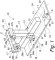
- Such machine tool 10 comprises:
- the nodal points are obviously understood to be regions where the components of the means of detection and monitoring are positioned.
- reference device 20 is part of the optical means 19 of detection and monitoring.
- Such optical means 19 comprise, as shown schematically in Figure 2 , at least one device 21 for detecting the translation of a nodal point of a controlled axis, for example of the nodal point B relating to the first part 12 and therefore to the axis X1, along two axes X2 and X3 which are perpendicular to the controlled axis X1.
- Such device 21 for detecting the translation of a nodal point comprises, for example, an emitter of a laser beam 22, which is adapted to be fixed to a part of the machine, for example to the footing 11, at a first nodal point, for example the nodal point A, and an element for receiving the light signal, for example an optical position sensor 23, known in the sector as a Position Sensitive Device (PSD), which is capable of measuring the position of a point of light emitted by the laser emitter 22 with respect to two axes which are mutually perpendicular, and is adapted to be positioned at a second nodal point, for example the nodal point B.
- PSD Position Sensitive Device
- the laser emitter 22 is arranged so as to be integral with a first part of the machine tool, for example, as mentioned, the footing 11, in such a way that its laser beam 24 is parallel to an axis X1 to detect and monitor for deformations, while the optical position sensor 23 is arranged so as to be integral with a second part of the machine, for example integral with the second part 14, which is designed to slide on the first part 12 of the machine along the axis X1.
- the optical position sensor 23 is positioned so that when calibration is complete the point of light produced by the laser beam 24 is at the origin of the reference axes X2 and X3 of the optical sensor 23.
- the optical means 19 comprise, as shown schematically in Figure 3 , at least one device 26 for detecting the rotation of a controlled axis, for example the axis X1, about two axes, X2 and X3, which are perpendicular to such controlled axis, and at a reference nodal point.
- Such device 26 for detecting the rotation of a controlled axis comprises, for example:
- the optical means 19 comprise, as an alternative to the device 21 for detecting the translation of a nodal point of a controlled axis and to the device 26 for detecting the rotation of a controlled axis, a device 35 for simultaneously detecting the translation of a nodal point of a controlled axis along two axes that are perpendicular to that same controlled axis, and the rotation of a controlled axis about two axes that are perpendicular to that same controlled axis.
- Such device 35 for simultaneously detecting translation and rotation of a controlled axis, for example X1, is shown schematically in Figure 4 .
- Such device 35 for simultaneously detecting translation and rotation of a controlled axis, for example the axis X1, comprises, for example:
- the optical means 19 can comprise a device 45 for simultaneously detecting the translation of two nodal points which are referred to corresponding mutually perpendicular controlled axes, for example the axes X1 and X2 in Figure 5 , along two axes that are perpendicular to each controlled axis.
- Such device 45 for simultaneously detecting the translation of two nodal points, for example B and C, which are referred to mutually perpendicular controlled axes, for example the axis X1 and the axis X2, comprises:
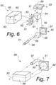
- the optical means 19 can comprise a device 55 for simultaneously detecting the translation of three nodal points, for example the nodal points B, C and D, which are referred to corresponding mutually perpendicular controlled axes, for example the axes X1, X2 and X3 in Figure 6 .
- Such device 55 for simultaneously detecting the translation of three mutually perpendicular controlled axes comprises:
- Such device 55 also comprises a 180° reflection element 65, for example a cubic reflector prism, known as a 'corner reflector', designed to be arranged so that it is integral with a machining head 18, and therefore referable to the fourth nodal point D, such machining head 18 being able to move with respect to the third part 16 of the machine.
- a 180° reflection element 65 for example a cubic reflector prism, known as a 'corner reflector', designed to be arranged so that it is integral with a machining head 18, and therefore referable to the fourth nodal point D, such machining head 18 being able to move with respect to the third part 16 of the machine.
- the means 19 of detection and monitoring can comprise a device 66 for detecting the translation of the controlled axis X3, with respect to which the machining head 18 slides, along two axes that are mutually perpendicular X1 and X2.
- Such device 66 shown for the purposes of example in Figure 7 , comprises a laser emitter 67 which is integral with the third part 16 of the machine, referable to the third nodal point C, a 180° reflection element 68, referable to the fourth nodal point D, which is integral with the machining head 18, and an optical position sensor 69 which is integral with the third part 16 of the machine, referable to the third nodal point C, toward which the laser beam is deflected.
- the means of detection and monitoring 19 comprise:
- the means 19 of detection and monitoring comprise:
- the PSD optical sensors and the laser emitters are managed by corresponding electronic boards.
- Such electronic boards are connected by way of a digital communication channel to a central control and management unit that conducts the actual communication with the CNC (Computer Numerical Control) of the machine tool 10.
- CNC Computer Numerical Control
- the central control and management unit can directly program each single electronic board in order to set parameters such as the sampling time and the number of samples to carry out for each acquisition.
- the values used are always those in output from the boards on board the optical sensors, therefore they are the result of an average of one second of acquisition.
- the scope of this mode is to give feedback on the state of the machine in a short time and in a form that is easily comparable with the calibration, hence the reason for the comparison in the same points.
- the control and management unit of the detection and monitoring means 19 interfaces with the CNC, at each sampling time providing the series of data detected.
- a program loaded in the CNC manages the data and carries out the necessary dimensional compensation.
- the control system sensors can be connected to the CNC through an Ethernet.
- each electronic board of each individual optical sensor the analog/digital conversion is performed directly, and that all the sensors interface with the electronic control and management unit by way of digital data, so as to reduce problems owing to analog errors, in order to decrease the number of wires necessary, and in order to obtain simple operations for maintenance and assistance.
- the data corresponding to the dimensional deviations and to the deformations of the parts of the machine tool 10 are adapted to be used for operations to compensate such deviations and deformations.
- the activity of automatically compensating mechanical deformations of the machine tool 10 follows the following operating method:
- Such device 21 for detecting the translation of a controlled axis comprises an emitter of a laser beam 22, which is adapted to be fixed to the footing 11, and referable to the first nodal point A, and an element for receiving the light signal, for example an optical position sensor 23, which is integral with the second part 14 and referable to the second nodal point B.
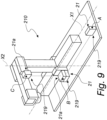
- the optical means of detecting and monitoring 219 comprising a first device 21 for detecting the translation of the axis X1, along two axes, X2 and X3, which are perpendicular to the controlled axis, and a second device 21a for detecting the translation of the axis X2, along two axes, X1 and X3, which are perpendicular to the controlled axis.
- the optical means of detecting and monitoring 319 comprising a device 55 for simultaneously detecting the translation of three mutually perpendicular controlled axes, as described above.
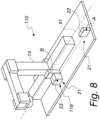
- Figure 10 shows:
- the reference device 420 is integral not with the footing 411 but with the second part 414 of the machine tool 410, therefore a first reference nodal point is constituted by the nodal point B referred to the second part 414 of the machine, a second reference nodal point is constituted by the reference nodal point C for the third part 416 of the machine, and a third reference nodal point is constituted by the reference nodal point D for the machining head 418; such solution is practicable if, for example, the first part 413 is integral with the footing 411 and structured so that its deformations are substantially negligible or fully detectable by way of the means of checking the position which are already integrated in the machine tool 410.
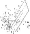
- a machine tool according to the invention is shown schematically in Figure 12 and designated therein with the reference numeral 510.
- the machine tool 510 is of the portal type, with a first part 512 which is constituted by two opposing shoulders 512a and 512b which are fixed to the footing 511, a second part 514 being arranged on each shoulder so as to slide along a first controlled axis X1 and being constituted by two opposing turrets 514a and 514b, which can slide in a parallel arrangement on the two shoulders 512a and 512b, which support a crossmember 514c.
- a third part 516 slides along a second controlled axis X2 on the crossmember 514c, and is constituted for example by a slider, supporting the machining head 518 which is adapted to translate along a third axis X3.
- the detection and monitoring means 519 comprise first means 519a for detecting and monitoring the deformations of the shoulders 512a and 512b, and second means 519b for detecting and monitoring the deformations of the crossmember 514c and of the machining head 518.
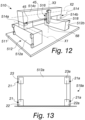
- the first detection and monitoring means 519a are shown for the purposes of example, in a first variation of embodiment thereof, in Figure 13 , where a first shoulder 512a is shown schematically, it being understood that the opposing second shoulder 512b is arranged in the same way.
- Such first detection and monitoring means 519a comprise two devices 21 and 21a for detecting the translation of the points where the corresponding optical sensor 23 and 23a is applied with respect to the points where the corresponding laser emitter 22 and 22a is positioned, these last items being integral with the footing 511.
- the two devices for detecting the translation 21 and 21a are positioned so as to operate with parallel laser beams, proximate to the lateral edges of each shoulder 512a and 512b.
- a first reference nodal point is determined to which to refer the deformations of the remaining second 514 and third 516 parts of the machine tool 510, i.e. the deviations and the rotations of the other reference nodal points.
- Such first means 619a comprise a single laser emitter 46, a deflector that partially transmits the light beam 49, and two optical sensors 47 and 50, similarly to what is described above for the device 45 for detecting and monitoring the translations of two axes, plus a reflector 80 adapted to deflect the light beam 90°.
- the laser emitter 46 integral with the footing at a first lower corner of the shoulder 512a, emits a beam toward a first optical sensor 47 arranged proximate to the upper corner of the shoulder 512a, above the laser emitter 46.
- the deflector that partially transmits the light beam 49 deflects a part of the light beam toward the reflector 80 positioned at the second lower corner of the shoulder 512a; the deflector 80 deflects the light beam toward the second optical sensor 50, positioned proximate to the upper corner of the shoulder 512a above the reflector 80.
- Such first means 619a have one laser emitter less with respect to the first means 519a.
- a machine tool has been devised with which it is possible to determine with precision the deviations of the machining head with respect to the specified operating positions and trajectories, so as to be able to correct them, thus periodically restoring the necessary operating precision to the machine.
Landscapes
- Engineering & Computer Science (AREA)
- Physics & Mathematics (AREA)
- General Physics & Mathematics (AREA)
- Mechanical Engineering (AREA)
- Automation & Control Theory (AREA)
- Human Computer Interaction (AREA)
- Manufacturing & Machinery (AREA)
- Electromagnetism (AREA)
- Optics & Photonics (AREA)
- Machine Tool Sensing Apparatuses (AREA)
Claims (9)
- Eine kartesisch numerisch gesteuerte Werkzeugmaschine (10) für hochpräzise Bearbeitung, umfassend:- einen Unterbau (11),- einen ersten Teil (12; 512) mit ersten Bewegungsmitteln (13) für die Bewegung eines zweiten Teils (14; 514) in Bezug auf eine erste gesteuerte Achse (X1), wobei der erste Teil (12; 512) auf dem Unterbau (11) montiert ist;- ein zweites Teil (14) mit zweiten Bewegungsmitteln (15) für die Bewegung eines dritten Teils (16; 516) in Bezug auf eine zweite gesteuerte Achse (X2),- ein drittes Teil (16; 516) mit dritten Bewegungsmitteln (17) für die Bewegung eines Bearbeitungskopfes (18) in Bezug auf eine dritte gesteuerte Achse (X3),- ein Bearbeitungskopf (18; 518),- mindestens einen Referenzknotenpunkt (A, B, C, D) für jede der einen oder mehreren gesteuerten Achsen (X1, X2, X3) in Bezug auf eine Referenzvorrichtung (20), die mit einem Teil der Werkzeugmaschine (10) integriert ist,
wobei ein Referenzknotenpunkt (A) auf dem Unterbau (11) festgelegt ist, ein Referenzknotenpunkt (B) auf dem ersten Teil (12; 512) festgelegt ist, ein Referenzknotenpunkt (C) auf dem zweiten Teil (14) festgelegt ist und ein Referenzknotenpunkt (D) auf dem dritten Teil (16; 516) festgelegt ist,- an Bord optische Mittel (19; 519) zum Erfassen und Überwachen der Position des mindestens einen Referenzknotenpunkts (B, C, D) für jede der einen oder mehreren der gesteuerten Achsen (X1, X2, X3) in Bezug auf das Referenzgerät (20) vorgesehen sind, wobei die Referenzvorrichtung (20) mit dem Unterbau (11) fest verbunden ist und mit dem auf dem Unterbau (11) festgelegten Referenzknotenpunkt (A) verbunden ist. - Kartesische Werkzeugmaschine nach Anspruch 1, dadurch gekennzeichnet, dass die optischen Mittel (19) mindestens ein Gerät (21) zum Erfassen der Verschiebung eines Referenzknotenpunkts für eine gesteuerte Achse entlang zweier Achsen umfassen, die senkrecht zu der gesteuerten Achse verlaufen.
- Kartesische Werkzeugmaschine nach einem der vorhergehenden Ansprüche, dadurch gekennzeichnet, dass die optischen Mittel (19) mindestens ein Gerät (26) zum Erfassen der Drehung einer gesteuerten Achse um zwei Achsen umfassen, die senkrecht zu der gesteuerten Achse an einem Referenzknotenpunkt verlaufen.
- Kartesische Werkzeugmaschine nach einem der vorhergehenden Ansprüche, dadurch gekennzeichnet, dass die optischen Mittel (19) mindestens eine Vorrichtung (35) zum gleichzeitigen Erfassen der Verschiebung eines Knotenpunkts einer gesteuerten Achse entlang zweier Achsen umfassen, die senkrecht zu der gesteuerten Achse stehen, und der Drehung einer gesteuerten Achse um zwei Achsen, die senkrecht zu der gesteuerten Achse am gleichen Referenzknotenpunkt stehen.
- Kartesische Werkzeugmaschine nach einem der vorhergehenden Ansprüche, dadurch gekennzeichnet, dass die optischen Mittel (19) mindestens eine Vorrichtung (45) zum gleichzeitigen Erfassen der Verschiebung zweier Referenzknotenpunkte umfassen, die sich jeweils auf eine Achse von zwei gesteuerten Achsen beziehen, die senkrecht zueinander entlang zweier Achsen stehen, die senkrecht zu jeder gesteuerten Achse stehen.
- Kartesische Werkzeugmaschine nach einem der vorhergehenden Ansprüche, dadurch gekennzeichnet, dass die optischen Mittel (19) mindestens eine Vorrichtung (55) zum gleichzeitigen Erfassen der Verschiebung der Knotenpunkte umfassen, die sich jeweils auf eine von drei gesteuerten Achsen beziehen, die senkrecht zueinanderstehen.
- Kartesische Werkzeugmaschine nach einem der vorhergehenden Ansprüche, dadurch gekennzeichnet, dass die optischen Mittel (19) mindestens eine Vorrichtung (66) zum Erfassen der Translation einer gesteuerten Achse (X3), entlang der der Bearbeitungskopf (18) gleitet, entlang zweier zueinander senkrechter Achsen (X1, X2) umfasst.
- Die kartesische Werkzeugmaschine nach einem der vorhergehenden Ansprüche, dadurch gekennzeichnet, dass die optischen Mittel (19) umfassen:- eine Vorrichtung (55) zum gleichzeitigen Erfassen der Translation der Knotenpunkte, die sich jeweils auf eine von drei gesteuerten Achsen beziehen, die wiederum umfasst:- einen Laseremitter (56), der mit dem Unterbau (11) fest verbunden ist,- einen ersten optischen PSD-Sensor (57), der mit dem zweiten Teil (14) fest verbunden ist, mit einem entsprechenden ersten Deflektor, der den Lichtstrahl teilweise durchlässt (59),- einen zweiten optischen PSD-Sensor (60), der mit dem dritten Teil (16) fest verbunden ist, mit einem entsprechenden zweiten Deflektor, der den Lichtstrahl teilweise durchlässt (64),- einen dritten optischen PSD-Sensor (62), der mit dem dritten Teil (16) fest verbunden ist,- ein 180°-Reflexionselement (65), das so voreingestellt ist, dass es mit dem Bearbeitungskopf (18) fest verbunden ist, und ferner:- eine erste Vorrichtung (26) zum Erfassen der Rotation einer ersten gesteuerten Achse (X1) mit einem Emitter eines Laserstrahls (27), der am Unterbau (11) befestigt ist, und ein vollreflektierender Spiegel (28), der mit dem zweiten Teil (14) der Maschine verbunden ist,- eine zweite Vorrichtung (26a) zum Erfassen der Drehung einer zweiten gesteuerten Achse (X2), mit einem Emitter eines Laserstrahls (27a), der am zweiten Teil (14) befestigt ist, und ein vollreflektierender Spiegel (28a), der mit dem dritten Teil (16) der Maschine verbunden ist,- eine dritte Vorrichtung (26b) zum Erfassen der Drehung einer dritten gesteuerten Achse (X3), mit einem Emitter eines Laserstrahls (27b), der mit dem dritten Teil (16) der Maschine verbunden ist und einen vollreflektierenden Spiegel (28b), der mit dem Bearbeitungskopf (18) integriert ist.
- Kartesische Werkzeugmaschine nach einem der Ansprüche 1 bis 7, dadurch gekennzeichnet, dass sie vom Portaltyp ist, wobei der erste Teil (512) aus zwei gegenüberliegenden Schultern (512a, 512b) besteht, die am Unterteil (511) befestigt sind, wobei der zweite Teil (514) auf jeder Schulter so angeordnet ist, dass er entlang einer ersten kontrollierten Achse (X1) gleitet, und aus zwei gegenüberliegenden Revolvern (514a, 514b) besteht, die in paralleler Anordnung auf den beiden Schultern (512a, 512b) gleiten können, die einen Querträger (514c) stützen, wobei der dritte Teil (516) auf dem Querträger (514c) entlang einer zweiten kontrollierten Achse (X2) gleitet und den Bearbeitungskopf (518) stützt, der angepasst ist, um entlang einer dritten Achse (X3) verschoben zu werden, wobei die Erfassungs- und Überwachungsmittel (519) erste Mittel (519a) zum Erfassen und Überwachen der Verformungen der Schultern (512a, 512b), und zweite Mittel (519b) zum Erfassen und Überwachen der Verformungen des Querträgers (514c) und des Bearbeitungskopfes (518) umfassen.
Applications Claiming Priority (2)
| Application Number | Priority Date | Filing Date | Title |
|---|---|---|---|
| ITUB20151398 | 2015-06-15 | ||
| PCT/EP2016/063721 WO2016202843A1 (en) | 2015-06-15 | 2016-06-15 | Cartesian numerically controlled machine tool for high-precision machining and optical apparatus for monitoring deformations for cartesian machine tools for high-precision machining |
Publications (3)
| Publication Number | Publication Date |
|---|---|
| EP3307481A1 EP3307481A1 (de) | 2018-04-18 |
| EP3307481B1 true EP3307481B1 (de) | 2024-10-23 |
| EP3307481C0 EP3307481C0 (de) | 2024-10-23 |
Family
ID=55358026
Family Applications (1)
| Application Number | Title | Priority Date | Filing Date |
|---|---|---|---|
| EP16731832.8A Active EP3307481B1 (de) | 2015-06-15 | 2016-06-15 | Kartesische numerisch gesteuerte werkzeugmaschine zur hochpräzisionsbearbeitung |
Country Status (5)
| Country | Link |
|---|---|
| US (1) | US20180173188A1 (de) |
| EP (1) | EP3307481B1 (de) |
| ES (1) | ES2993431T3 (de) |
| TW (1) | TW201701089A (de) |
| WO (1) | WO2016202843A1 (de) |
Families Citing this family (9)
| Publication number | Priority date | Publication date | Assignee | Title |
|---|---|---|---|---|
| IT201700038356A1 (it) * | 2017-04-07 | 2018-10-07 | Hpt Sinergy Srl | Macchina utensile cartesiana a controllo numerico per lavorazioni ad alta precisione e apparecchiatura ottica di monitoraggio delle deformazioni per macchine utensili cartesiane per lavorazioni ad alta precisione |
| IT201700038358A1 (it) * | 2017-04-07 | 2018-10-07 | Hpt Sinergy Srl | Macchina utensile cartesiana a controllo numerico per lavorazioni ad alta precisione e apparecchiatura ottica di monitoraggio delle deformazioni per macchine utensili cartesiane per lavorazioni ad alta precisione |
| IT201700122296A1 (it) * | 2017-10-27 | 2019-04-27 | Hpt Sinergy Srl | Macchina utensile cartesiana a controllo numerico perfezionata per lavorazioni ad alta precisione e apparecchiatura di monitoraggio delle deformazioni per macchine utensili cartesiane per lavorazioni ad alta precisione |
| JP7124321B2 (ja) * | 2018-01-18 | 2022-08-24 | トヨタ自動車株式会社 | 情報処理装置、データ管理システム、データ管理方法及びプログラム |
| TWD193440S (zh) | 2018-02-14 | 2018-10-11 | 財團法人中興工程顧問社 | Monitoring framework |
| CN110293431B (zh) * | 2019-06-24 | 2020-08-28 | 中国航发动力股份有限公司 | 一种五轴机床零点标定方法及装夹装置 |
| TWI749961B (zh) * | 2020-12-22 | 2021-12-11 | 雷應科技股份有限公司 | 刀具檢測器 |
| US20240181587A1 (en) * | 2021-04-07 | 2024-06-06 | Shaper Tools, Inc. | Systems, methods and apparatus for control of positioning systems |
| US12231802B2 (en) | 2021-08-04 | 2025-02-18 | Theia Scientific, LLC | System and method for multi-modal microscopy |
Family Cites Families (7)
| Publication number | Priority date | Publication date | Assignee | Title |
|---|---|---|---|---|
| DE3334460A1 (de) * | 1983-09-23 | 1985-04-11 | Fa. Carl Zeiss, 7920 Heidenheim | Mehrkoordinaten-messmaschine |
| GB2188571B (en) * | 1986-04-05 | 1990-02-21 | Butterley Engineering Limited | Machine measurement systems |
| GB8616431D0 (en) * | 1986-07-05 | 1986-08-13 | Renishaw Plc | Locating co-ordinates of object |
| EP1688807B2 (de) * | 2005-02-04 | 2014-06-18 | TRUMPF Werkzeugmaschinen GmbH + Co. KG | Verfahren zur Bewegungsaufteilung einer Relativbewegung zwischen einem Werkstück und einem Werkzeug einer Werkzeugmaschine |
| WO2008065683A1 (en) * | 2006-11-27 | 2008-06-05 | Sintesi S.C.P.A. | Optoelectronic measuring system for acquiring position and orientation measures in an industrial machine |
| WO2009001385A1 (en) * | 2007-06-28 | 2008-12-31 | Hexagon Metrology S.P.A. | Method for determining dynamic errors in a measuring machine |
| EP2270425A1 (de) * | 2009-07-03 | 2011-01-05 | Leica Geosystems AG | Koordinatenmessmaschine und Verfahren zum Kompensieren von Fehlern in einer Koordinatenmessmaschine |
-
2016
- 2016-06-15 EP EP16731832.8A patent/EP3307481B1/de active Active
- 2016-06-15 US US15/736,650 patent/US20180173188A1/en not_active Abandoned
- 2016-06-15 WO PCT/EP2016/063721 patent/WO2016202843A1/en not_active Ceased
- 2016-06-15 ES ES16731832T patent/ES2993431T3/es active Active
- 2016-06-15 TW TW105118694A patent/TW201701089A/zh unknown
Also Published As
| Publication number | Publication date |
|---|---|
| US20180173188A1 (en) | 2018-06-21 |
| WO2016202843A1 (en) | 2016-12-22 |
| EP3307481A1 (de) | 2018-04-18 |
| ES2993431T3 (en) | 2024-12-30 |
| EP3307481C0 (de) | 2024-10-23 |
| TW201701089A (zh) | 2017-01-01 |
Similar Documents
| Publication | Publication Date | Title |
|---|---|---|
| EP3307481B1 (de) | Kartesische numerisch gesteuerte werkzeugmaschine zur hochpräzisionsbearbeitung | |
| JP2510216B2 (ja) | 産業用ロボットのセンサを校正するための方法 | |
| US9915516B2 (en) | Method for controlling shape measuring apparatus | |
| EP1239263B1 (de) | Positionsmessvorrichtung und Bearbeitungsapparat mit dieser Vorrichtung | |
| EP2019345A1 (de) | Verfahren zur Messung des Positionserkennungsfehlers für eine Werkzeugmaschine | |
| JP2019014035A (ja) | Cnc機械の幾何学的誤差および精度の監視および評価法 | |
| JP2928355B2 (ja) | レーザ心合せ方法及びその検査装置 | |
| CN101861510A (zh) | 对准多臂测量机的臂参考系的方法 | |
| JP3202162B2 (ja) | 数値制御工作機械の全自動測定システム、全自動測定方法及び数値制御工作機械 | |
| WO2018187690A1 (en) | System and method for machine workpiece alignment | |
| EP4343278A1 (de) | Kalibrierung eines koordinatenmessgeräts | |
| EP1439441A2 (de) | Verfahren zur Kennzeichnung und Management von Fehlern und Defekten in Montage- und Schweisslinien für Kraftfahrzeugkarosserien, Karosserieteilen oder dergleichen und Anlage nach diesem Verfahren | |
| US6286055B1 (en) | Error correction apparatus for NC machine tool | |
| JP7306883B2 (ja) | 座標測定機、及び座標測定プログラム | |
| KR102460118B1 (ko) | 어태치먼트 중심위치의 보정방법 | |
| EP3315898B1 (de) | Steuerungssystem, steuerungsverfahren und programm für steuerungssystem | |
| CN108235695B (zh) | 加工装置、加工方法及有形的非临时性记录介质 | |
| EP3189302A1 (de) | Koordinatenmessverfahren und vorrichtung zum überprüfen von werkstücken mit erzeugung von messkorrekturwerten anhand einer bekannterweise von einer perfekten form nicht wesentlich abweichenden referenzform | |
| US20230114210A1 (en) | Batch production system and batch production method | |
| KR102508280B1 (ko) | 틸팅 헤드용 회전중심 보정장치 | |
| RU140033U1 (ru) | Устройство контроля и измерения действительных размеров параметров наружных поверхностей и радиусов изделия типа оболочка вращения | |
| KR102197729B1 (ko) | 산업기계설비 진단 및 위치제어시스템 | |
| CN121083393B (zh) | 一种设备基础自动检测系统 | |
| JP7026278B1 (ja) | 運動精度評価装置 | |
| RU2420712C1 (ru) | Устройство активного контроля и измерения действительных размеров наружной поверхности изделия типа оболочка вращения |
Legal Events
| Date | Code | Title | Description |
|---|---|---|---|
| STAA | Information on the status of an ep patent application or granted ep patent |
Free format text: STATUS: THE INTERNATIONAL PUBLICATION HAS BEEN MADE |
|
| PUAI | Public reference made under article 153(3) epc to a published international application that has entered the european phase |
Free format text: ORIGINAL CODE: 0009012 |
|
| STAA | Information on the status of an ep patent application or granted ep patent |
Free format text: STATUS: REQUEST FOR EXAMINATION WAS MADE |
|
| 17P | Request for examination filed |
Effective date: 20180110 |
|
| AK | Designated contracting states |
Kind code of ref document: A1 Designated state(s): AL AT BE BG CH CY CZ DE DK EE ES FI FR GB GR HR HU IE IS IT LI LT LU LV MC MK MT NL NO PL PT RO RS SE SI SK SM TR |
|
| AX | Request for extension of the european patent |
Extension state: BA ME |
|
| DAV | Request for validation of the european patent (deleted) | ||
| DAX | Request for extension of the european patent (deleted) | ||
| STAA | Information on the status of an ep patent application or granted ep patent |
Free format text: STATUS: EXAMINATION IS IN PROGRESS |
|
| 17Q | First examination report despatched |
Effective date: 20190612 |
|
| GRAP | Despatch of communication of intention to grant a patent |
Free format text: ORIGINAL CODE: EPIDOSNIGR1 |
|
| STAA | Information on the status of an ep patent application or granted ep patent |
Free format text: STATUS: GRANT OF PATENT IS INTENDED |
|
| INTG | Intention to grant announced |
Effective date: 20240718 |
|
| GRAS | Grant fee paid |
Free format text: ORIGINAL CODE: EPIDOSNIGR3 |
|
| GRAA | (expected) grant |
Free format text: ORIGINAL CODE: 0009210 |
|
| STAA | Information on the status of an ep patent application or granted ep patent |
Free format text: STATUS: THE PATENT HAS BEEN GRANTED |
|
| AK | Designated contracting states |
Kind code of ref document: B1 Designated state(s): AL AT BE BG CH CY CZ DE DK EE ES FI FR GB GR HR HU IE IS IT LI LT LU LV MC MK MT NL NO PL PT RO RS SE SI SK SM TR |
|
| REG | Reference to a national code |
Ref country code: GB Ref legal event code: FG4D |
|
| REG | Reference to a national code |
Ref country code: CH Ref legal event code: EP |
|
| REG | Reference to a national code |
Ref country code: DE Ref legal event code: R096 Ref document number: 602016089933 Country of ref document: DE |
|
| REG | Reference to a national code |
Ref country code: IE Ref legal event code: FG4D |
|
| REG | Reference to a national code |
Ref country code: ES Ref legal event code: FG2A Ref document number: 2993431 Country of ref document: ES Kind code of ref document: T3 Effective date: 20241230 |
|
| U01 | Request for unitary effect filed |
Effective date: 20241122 |
|
| U07 | Unitary effect registered |
Designated state(s): AT BE BG DE DK EE FI FR IT LT LU LV MT NL PT RO SE SI Effective date: 20241129 |
|
| PG25 | Lapsed in a contracting state [announced via postgrant information from national office to epo] |
Ref country code: IS Free format text: LAPSE BECAUSE OF FAILURE TO SUBMIT A TRANSLATION OF THE DESCRIPTION OR TO PAY THE FEE WITHIN THE PRESCRIBED TIME-LIMIT Effective date: 20250223 Ref country code: HR Free format text: LAPSE BECAUSE OF FAILURE TO SUBMIT A TRANSLATION OF THE DESCRIPTION OR TO PAY THE FEE WITHIN THE PRESCRIBED TIME-LIMIT Effective date: 20241023 |
|
| PG25 | Lapsed in a contracting state [announced via postgrant information from national office to epo] |
Ref country code: NO Free format text: LAPSE BECAUSE OF FAILURE TO SUBMIT A TRANSLATION OF THE DESCRIPTION OR TO PAY THE FEE WITHIN THE PRESCRIBED TIME-LIMIT Effective date: 20250123 |
|
| PG25 | Lapsed in a contracting state [announced via postgrant information from national office to epo] |
Ref country code: GR Free format text: LAPSE BECAUSE OF FAILURE TO SUBMIT A TRANSLATION OF THE DESCRIPTION OR TO PAY THE FEE WITHIN THE PRESCRIBED TIME-LIMIT Effective date: 20250124 |
|
| PG25 | Lapsed in a contracting state [announced via postgrant information from national office to epo] |
Ref country code: PL Free format text: LAPSE BECAUSE OF FAILURE TO SUBMIT A TRANSLATION OF THE DESCRIPTION OR TO PAY THE FEE WITHIN THE PRESCRIBED TIME-LIMIT Effective date: 20241023 |
|
| PG25 | Lapsed in a contracting state [announced via postgrant information from national office to epo] |
Ref country code: RS Free format text: LAPSE BECAUSE OF FAILURE TO SUBMIT A TRANSLATION OF THE DESCRIPTION OR TO PAY THE FEE WITHIN THE PRESCRIBED TIME-LIMIT Effective date: 20250123 |
|
| PG25 | Lapsed in a contracting state [announced via postgrant information from national office to epo] |
Ref country code: SM Free format text: LAPSE BECAUSE OF FAILURE TO SUBMIT A TRANSLATION OF THE DESCRIPTION OR TO PAY THE FEE WITHIN THE PRESCRIBED TIME-LIMIT Effective date: 20241023 |
|
| PGFP | Annual fee paid to national office [announced via postgrant information from national office to epo] |
Ref country code: GB Payment date: 20250617 Year of fee payment: 10 |
|
| PG25 | Lapsed in a contracting state [announced via postgrant information from national office to epo] |
Ref country code: SK Free format text: LAPSE BECAUSE OF FAILURE TO SUBMIT A TRANSLATION OF THE DESCRIPTION OR TO PAY THE FEE WITHIN THE PRESCRIBED TIME-LIMIT Effective date: 20241023 |
|
| PGFP | Annual fee paid to national office [announced via postgrant information from national office to epo] |
Ref country code: TR Payment date: 20250528 Year of fee payment: 10 |
|
| PG25 | Lapsed in a contracting state [announced via postgrant information from national office to epo] |
Ref country code: CZ Free format text: LAPSE BECAUSE OF FAILURE TO SUBMIT A TRANSLATION OF THE DESCRIPTION OR TO PAY THE FEE WITHIN THE PRESCRIBED TIME-LIMIT Effective date: 20241023 |
|
| U20 | Renewal fee for the european patent with unitary effect paid |
Year of fee payment: 10 Effective date: 20250624 |
|
| PLBE | No opposition filed within time limit |
Free format text: ORIGINAL CODE: 0009261 |
|
| STAA | Information on the status of an ep patent application or granted ep patent |
Free format text: STATUS: NO OPPOSITION FILED WITHIN TIME LIMIT |
|
| 26N | No opposition filed |
Effective date: 20250724 |
|
| PGFP | Annual fee paid to national office [announced via postgrant information from national office to epo] |
Ref country code: ES Payment date: 20250710 Year of fee payment: 10 |
|
| REG | Reference to a national code |
Ref country code: CH Ref legal event code: H13 Free format text: ST27 STATUS EVENT CODE: U-0-0-H10-H13 (AS PROVIDED BY THE NATIONAL OFFICE) Effective date: 20260127 |
|
| PG25 | Lapsed in a contracting state [announced via postgrant information from national office to epo] |
Ref country code: MC Free format text: LAPSE BECAUSE OF FAILURE TO SUBMIT A TRANSLATION OF THE DESCRIPTION OR TO PAY THE FEE WITHIN THE PRESCRIBED TIME-LIMIT Effective date: 20241023 |
|
| PG25 | Lapsed in a contracting state [announced via postgrant information from national office to epo] |
Ref country code: IE Free format text: LAPSE BECAUSE OF NON-PAYMENT OF DUE FEES Effective date: 20250615 |