EP1438232B1 - Apparatus and method for roll packing compressible materials - Google Patents
Apparatus and method for roll packing compressible materials Download PDFInfo
- Publication number
- EP1438232B1 EP1438232B1 EP02802152A EP02802152A EP1438232B1 EP 1438232 B1 EP1438232 B1 EP 1438232B1 EP 02802152 A EP02802152 A EP 02802152A EP 02802152 A EP02802152 A EP 02802152A EP 1438232 B1 EP1438232 B1 EP 1438232B1
- Authority
- EP
- European Patent Office
- Prior art keywords
- mandrel
- roll
- compressible material
- packing
- shaft
- Prior art date
- Legal status (The legal status is an assumption and is not a legal conclusion. Google has not performed a legal analysis and makes no representation as to the accuracy of the status listed.)
- Expired - Lifetime
Links
- 239000000463 material Substances 0.000 title claims abstract description 121
- 238000012856 packing Methods 0.000 title claims abstract description 75
- 238000000034 method Methods 0.000 title claims abstract description 15
- 230000006835 compression Effects 0.000 claims abstract description 50
- 238000007906 compression Methods 0.000 claims abstract description 50
- 238000004804 winding Methods 0.000 claims description 12
- 238000011144 upstream manufacturing Methods 0.000 claims description 6
- 230000007423 decrease Effects 0.000 claims description 5
- 238000004026 adhesive bonding Methods 0.000 claims description 4
- 239000000853 adhesive Substances 0.000 claims description 3
- 230000001070 adhesive effect Effects 0.000 claims description 3
- 238000005520 cutting process Methods 0.000 claims description 3
- 230000000712 assembly Effects 0.000 description 43
- 238000000429 assembly Methods 0.000 description 43
- 239000006260 foam Substances 0.000 description 13
- 238000004806 packaging method and process Methods 0.000 description 8
- 230000004888 barrier function Effects 0.000 description 6
- 238000003860 storage Methods 0.000 description 4
- 238000004519 manufacturing process Methods 0.000 description 3
- 239000002657 fibrous material Substances 0.000 description 2
- 239000006261 foam material Substances 0.000 description 2
- 230000007246 mechanism Effects 0.000 description 2
- 239000000123 paper Substances 0.000 description 2
- 230000008569 process Effects 0.000 description 2
- 230000008859 change Effects 0.000 description 1
- 230000001419 dependent effect Effects 0.000 description 1
- 239000004744 fabric Substances 0.000 description 1
- -1 finished mattresses Substances 0.000 description 1
- 239000011888 foil Substances 0.000 description 1
- 238000012986 modification Methods 0.000 description 1
- 230000004048 modification Effects 0.000 description 1
- 239000004033 plastic Substances 0.000 description 1
- 230000002028 premature Effects 0.000 description 1
- 238000005096 rolling process Methods 0.000 description 1
- 238000007789 sealing Methods 0.000 description 1
Images


Classifications
-
- B—PERFORMING OPERATIONS; TRANSPORTING
- B65—CONVEYING; PACKING; STORING; HANDLING THIN OR FILAMENTARY MATERIAL
- B65B—MACHINES, APPARATUS OR DEVICES FOR, OR METHODS OF, PACKAGING ARTICLES OR MATERIALS; UNPACKING
- B65B63/00—Auxiliary devices, not otherwise provided for, for operating on articles or materials to be packaged
- B65B63/02—Auxiliary devices, not otherwise provided for, for operating on articles or materials to be packaged for compressing or compacting articles or materials prior to wrapping or insertion in containers or receptacles
- B65B63/024—Auxiliary devices, not otherwise provided for, for operating on articles or materials to be packaged for compressing or compacting articles or materials prior to wrapping or insertion in containers or receptacles for compressing by winding
-
- B—PERFORMING OPERATIONS; TRANSPORTING
- B65—CONVEYING; PACKING; STORING; HANDLING THIN OR FILAMENTARY MATERIAL
- B65B—MACHINES, APPARATUS OR DEVICES FOR, OR METHODS OF, PACKAGING ARTICLES OR MATERIALS; UNPACKING
- B65B11/00—Wrapping, e.g. partially or wholly enclosing, articles or quantities of material, in strips, sheets or blanks, of flexible material
- B65B11/56—Rolling articles with wrappers along a supporting surface
Definitions
- This invention relates to the packaging of compressible materials such as mattresses and foam and spring assemblies used in the manufacture of mattresses and the like, and is more particularly directed to an apparatus for packaging such compressible materials into a roll.
- Roll packing generally involves winding-up a desired material to form a roll and then securing the roll to prevent uncoiling of the roll during handling.
- compressible materials such as mattresses and foam or spring cores
- Various devices have been used to achieve compression of roll packed materials.
- U.S. Patent No. 3,927,504 to Forrister discloses an apparatus for rolling resilient foamed sheet material without the use of a mandrel. This machine is not useful for packaging spring assemblies and does not have the capability to package multiple units of a compressible material into a large roll.
- the device further does not provide for packaging a compressible material with a barrier layer between successive turns of the roll, which barrier layer is desirable to prevent adhesion between successive layers of foam.
- Some roll packing systems further include a mandrel which facilitates winding the material.
- a spring packing machine having a radially collapsible arbor for use in roll packing spring assemblies. A barrier layer between successive turns of the roll keeps the spring assemblies separate and permits easy removal of a single assembly from the roll.
- this machine is not useful for roll packing foam material due to the presence of a pressure bar 50, between belt 15 and the collapsible arbor, which would tend to snag a compressed foam as it passed beneath.
- Roll packing machines of the prior art are generally very labour intensive, requiring the close attention of an operator at various stages of the roll packing process.
- an operator in the apparatus disclosed by Wunderlich, an operator must manually start the feeding of packing material to a mandrel for winding the spring assemblies into a roll. Operators must also manually feed the compressible spring assemblies to the mandrel and manually cut and secure the packing material at the end of a roll to prevent premature uncoiling of the roll packed assemblies.
- the operator When a roll of spring assemblies is complete, the operator must remove the mandrel from the machine and manually collapse the mandrel to remove the finished roll. The arbor must then be replaced in the machine before another roll can be formed.
- US Patent No. 6,098,378 to Wyatt and US Patent No.
- US Patent No. 2,668,405 to Droll discloses a machine for winding mattresses including a mandrel that can move between expanded and collapsed states using sliding linkages, in accordance with the preamble of appended claim 1.
- the present invention provides a simple machine for roll packing a variety of compressible materials such as foam cores, spring assemblies, and fiber materials used in the manufacture of mattress products, as well as finished mattresses themselves.
- the machine has a radially collapsible mandrel that permits finished roll packed materials to be easily removed from the machine by sliding the roll off of the mandrel.
- This radially collapsible mandrel permits rolled materials to be removed without any telescoping or tearing of the materials which is usually caused by binding of the roll packed material on the mandrel.
- the machine of the present invention is especially useful in roll packing foam materials which are highly susceptible to binding against a mandrel.
- the simplicity of design of the machine of the present invention further permits use in roll packing practically any compressible material, even materials as diverse as coiled spring assemblies for mattresses and foam cores.
- a pneumatic cylinder is used to adjust the position of the compression roller relative to the mandrel.
- the mandrel is supported on a pivot arm which rotates to vary the spacing between the mandrel and the compression roller.
- the mandrel is driven at one end by a driving mechanism including, for example, a motor and gearbox, and has a bearing plate at the opposite end.
- the bearing plate is movable away from the end of the mandrel so that a finished roll of material can be easily pushed off of the mandrel after it has been collapsed.
- the apparatus includes a roll pusher associated with the mandrel to facilitate the removal of finished rolls from the mandrel, and further includes a roll handler for receiving the finished roll as it is pushed off the mandrel.
- the invention provides a simple apparatus and method for roll packing a variety of compressible materials and which has a collapsible mandrel that facilitates the easy removal of finished rolls without tearing, telescoping, or otherwise damaging the roll packed material.
- An apparatus and method are provided for roll packing compressible materials in a simple and efficient manner without damaging the materials, and wherein the materials can be stored and shipped in a compact state.
- the present invention may be described and understood by a description of an exemplary apparatus.
- the apparatus 10 includes a collapsible mandrel 12 for receiving in-fed materials 14 and winding them into a roll.
- the mandrel 12 is fixed to a shaft 16 that is driven at a first end 18 by a driving mechanism, for example motor 20 and gearbox 22 connected to the shaft 16.
- the invention further includes a compression roller 24, which is located proximate the mandrel 12 and which is fixed to a compression roller shaft 26 that is substantially parallel to the mandrel shaft 16.
- the rotational axis of mandrel 12 is substantially parallel to the rotational axis of compression roller 24.
- the compression roller 24 is adjustable such as by means of an actuator 28 fixed to the roller shaft 26 whereby the spacing 30 (see FIGS. 2 and 4A ) between the compression roller 24 and the mandrel 12 may be adjusted to vary or maintain the amount of compression on the in-fed materials 14.
- a feed table 32 located upstream of the mandrel 12 and compression roller 24 directs in-fed compressible materials 14 between the mandrel 12 and compression roller 24 as the material 14 is wound upon the mandrel 12.
- the feed table 32 includes a jig plate to ensure proper alignment of the in-fed materials 14 with respect to the mandrel 12 and compression roller 24.
- a disc brake 34 may be attached to the roller shaft 26 to control rotation of the compression roller 24.
- the apparatus 10 further includes a packing material dispenser 36 which supplies packing material 38, such as paper, plastic or fiber material, to a surface 40 of the in-fed compressible materials 14 as they are fed through the mandrel 12 and compression roller 24.
- packing material is then wound with the compressed in-fed material to create a barrier layer between successive turns of the rolled material.
- the barrier layer protects successive layers of in-fed material such as foam and prevents adhesion of the successive layers.
- the packing material dispenser 36 may further include a guide roller 42, pinch rollers 44, 46, and a tension roller 48 to aid in directing packing material 38 to the in-fed compressible material 14 and also to maintain proper tension and alignment of the packing material 38.
- a bearing plate 50 is located at a second end 52 of the mandrel shaft 16, opposite the drive motor 20, and is movable to expose an end of the mandrel 12 so that a finished roll of material 54 may be removed from the mandrel 12.
- the apparatus further includes a roll handler 58 for facilitating easy removal of the finished rolls 54.
- the roll handler 58 is a trough-shaped cradle that is pivotally connected to a support (not shown) and can be placed in a first position near the end of the mandrel 12 for receiving a finished roll of material 54.
- a roll pusher 60 associated with the mandrel 12 aids in removing a finished roll 54 from the collapsed mandrel 12 onto the roll handler 58.
- the roll handler 58 may then be placed in a second position (shown in phantom) to permit operators to subsequently remove the roll 54 from the machine 10.
- the collapsible mandrel 12 includes a series of elongated plates 62 attached to the mandrel shaft 16 and positioned about the shaft 16 in an overlapping arrangement to create a substantially tubular surface 64 along the length of the shaft 16.
- the plates 62 are slidably connected to the shaft 16 and move toward or away from the shaft 16 along radially extending paths 66 to increase or decrease the diameter 67 of the tubular surface 64 formed by the overlapping plates 62.
- Rods 68 connected to each plate 62 engage a cam 70 attached to the shaft 16, whereby rotational operation of the cam 70 causes the plates 62 to move either toward or away from the shaft 16 to correspondingly collapse or expand the mandrel diameter 67.
- the spacing 30 between the mandrel 12 and compression roller 24 is adjusted to provide a desired amount of compression in the in-fed compressible material 14.
- Packing material 38 from the packing material dispenser 36 is fed through the guide roller 42, pinch rollers 44, 46, and tension roller 48 and then directed between the compression roller 24 and mandrel 12 while the mandrel 12 is turned to wind an initial length of packing material 38 upon the mandrel 12, as depicted in FIG 4A .
- In-fed compressible material 14 which is supported on feed table 32, is directed between the mandrel 12 and compression roller 24.
- the motor 20 ( FIG.
- the actuator 28 ( FIG. 1 ) attached to the compression roller shaft 26 may be operated to vary the spacing 30 between the mandrel 12 and compression roller 24 as the roll 54 gets bigger, as can be seen in FIG. 4B , to maintain uniform compression in the roll 54.
- the motor 20 is stopped.
- the finished roll 54 is secured, for example, with tape, straps, or other suitable material, and bearing plate 50 ( FIG. 1 ) is moved to expose an end of the mandrel 12.
- the mandrel 12 is then collapsed, as depicted in FIG. 4C , so that the finished roll 54 may be removed from the mandrel 12 under the operation of the roll pusher 60 ( FIG. 1 ).
- the roll pusher 60 pushes the finished roll 54 into the roll handler 58 ( FIG. 1 ) and the roll handler 58 then pivots to a second position so that operators can maneuver the finished roll 54 away from the machine 10.
- the apparatus 110 includes a radially collapsible mandrel 112 for receiving in-fed spring assemblies 114 and winding them into a roll.
- Collapsible mandrel 112 is attached to a pivot arm 116 having pivot axis 118.
- the collapsible mandrel 112 has a rotational axis 120 which is substantially parallel to the pivot axis 118.
- a fixed compression roller 122 is located proximate the mandrel 112 and has a rotational axis 124 substantially parallel to the rotational axis 120 of the mandrel 112.
- Pivot arm 116 pivots about pivot axis 118 to position the mandrel 112 relative to the fixed compression roller 122 to compress in-fed spring assemblies 114 in a controllable manner as they are wound upon the mandrel 112.
- the apparatus 110 further includes a precompression guide roller 126 upstream of the mandrel 112 for receiving in-fed spring assemblies 114 and directing them toward the mandrel 112 and fixed compression roller 122.
- the precompression guide roller 126 provides a gradual initial compression of the spring assemblies 114 prior to being further compressed between the mandrel 112 and fixed compression roller 122, as illustrated in FIG. 6 .
- the precompression guide roller 126 provides precompression to spring assemblies 114 having tall or small diameter springs which are susceptible to shifting that would otherwise occur if they were subjected to rapid compression by being directed to the fixed compression roller 122 and mandrel 112 without any precompression.
- a feed table 128 upstream of the precompression guide roller 126 supports in-fed spring assemblies 114 and directs them toward the precompression guide roller 126.
- the feed table 128 includes a plurality of rollers 130 disposed on a support surface 132 of the feed table 128 to transport spring assemblies 114 toward the precompression guide roller 126.
- the feed table 128 further includes a precompression conveyer 134 which operates in conjunction with the precompression guide roller 126 to precompress spring assemblies 114 and automatically feed the spring assemblies 114 between the mandrel 112 and fixed compression roller 122.
- Moving side guides 136 on the feed table 128 aid in automatically in-feeding the spring assemblies 114 and ensure proper spacing between the in-fed spring assemblies 114.
- the feed table 128 includes a frame 138 having casters 140 located at the bottom of the frame 138 to allow movement of the feed table 128 toward and away from the precompression guide roller 126.
- the casters 140 are positioned on guide rails 142 which control the path of the feed table 128.
- Drive motors (not shown) coupled to the feed table frame 138, the feed table rollers 130, the side guides 136, and the precompression conveyor 134 provide the motive forces to move spring assemblies 114 along the feed table 128 and between the precompression roller 126 and conveyor 134 to be directed to the mandrel 112 for winding.
- the apparatus 110 includes one or more packing material dispensers 152 positioned near the mandrel 112 for receiving and dispensing packing material 154, such as paper, foil, or various fabric materials, to the in-fed spring assemblies 114 as they are being wound upon the mandrel 112.
- packing material dispenser 152 has associated packing material feed rollers 156 and a tension compensator 158 for feeding and directing packing material 154 from the dispenser 152 toward the mandrel 112 and fixed compression roller 122.
- the packing material feed rollers may be supported on pneumatic cylinders whereby the position of the feed rollers may be adjusted.
- the mandrel 112 includes a vacuum system which draws the packing material 154 toward a surface 160 of the mandrel 112 so that it is wound tightly upon the mandrel 112 prior to compressing and winding of spring assemblies 114 upon the mandrel 112.
- pivot arm 116 pivots about pivot axis 118 to move the mandrel 112 away from the fixed compression roller 122 in a controlled manner so that successive spring assemblies 114 are uniformly compressed and rolled upon the mandrel 112.
- the apparatus 110 further includes an automated cutting and gluing unit 162 in line between the packing material dispensers 152 and the mandrel 112.
- the cutting and gluing unit 162 automatically cuts the packing material 154 near the end of a finished roll 164 of compressed spring assemblies 114 and applies adhesive to a final layer of packing material 154, which is wound to secure the finished roll 164.
- pivot arm 116 holds the finished roll 164, still on the mandrel 112, against the fixed compression roller 122 to provide pressure to the end of the final layer of packing material 154 until the adhesive has cured and the finished roll 164 may be removed from the mandrel 112.
- pivot arm 116 rotates to move the finished roll 164 away from the fixed compression roller 122 and places the finished roll 164 on a finished roll support 166.
- the mandrel 112 may be collapsed radially inward to release the finished roll 164 and a roll pusher 168 is activated to push the finished roll 164 off the mandrel 112 along the finished roll support 166.
- the apparatus 110 further includes a controller 170 connected to the various drive motors and to sensors positioned at various locations on the apparatus 110 for controlling the automated roll packing of spring assemblies 114, as described above.
- the controller 170 is also configured to count the number of spring assemblies 114 that have been wound upon the mandrel 112.
- a power supply 172 provides electrical current to the apparatus 110 and its components. While the apparatus 110 is designed for completely automated roll packing of spring assemblies, it can also be used without an automated feed table 128 when manual feeding of spring assemblies 114 is desired.
- the roll packing apparatus 110 includes a frame structure 174 for supporting the components described above.
- the frame structure 174 may be configured to have a modular design, wherein various sections of the apparatus 110 may be separately assembled and disassembled to facilitate transportation and assembly of the apparatus 110.
- an automated system 180 for providing roll packed spring assemblies 114 includes a roll packing apparatus 110, as described above, and further includes a finished roll manipulator 182 which receives finished rolls 164 of spring assemblies 114 from the finished roll support 166 and moves them to a finished roll palletizer 184.
- the finished roll palletizer 184 includes a pallet magazine 186, a roll wrapping machine 188 for wrapping finished rolls 164 for shipment and storage, and a conveyor 190.
- a roll packing apparatus 110 has a radially collapsible mandrel 112 having a diameter of about 300 mm.
- the exemplary apparatus 110 can receive rolls of packing material 154 up to about 2100 mm in width and about 1000 mm in diameter, and can accommodate spring assemblies 114 up to about 200-mm wide and about 240-mm high.
- the exemplary apparatus 110 can produce finished rolls 164 of spring assemblies 114 of up to about 650 mm in diameter, each roll containing 10-12 spring assemblies 114, at a rate of about 12-20 rolls per hour.
Landscapes
- Engineering & Computer Science (AREA)
- Mechanical Engineering (AREA)
- Packaging Of Special Articles (AREA)
- Auxiliary Devices For And Details Of Packaging Control (AREA)
- Basic Packing Technique (AREA)
Abstract
Description
- This invention relates to the packaging of compressible materials such as mattresses and foam and spring assemblies used in the manufacture of mattresses and the like, and is more particularly directed to an apparatus for packaging such compressible materials into a roll.
- Conventional packaging and transportation of compressible materials such as finished mattresses, as well as foam or spring assemblies used in the manufacture of mattress products, generally involves handling of the materials in an uncompressed state. As such, the shipping and storage of the materials requires much more space than would be required if the materials were provided in a compressed state. To improve the efficiency of shipping and storage, foam mattress cores have been packaged in a compressed state by flattening the foam and sealing it in an evacuated bag. See, for example,
U.S. Patent No. 4,711,067 to Magni . This method of packaging foam cores, however, is not useful in packaging spring assemblies. In addition, storage and transportation efficiencies of the foam could be further improved by packaging the flattened cores into a tight roll. - Roll packing generally involves winding-up a desired material to form a roll and then securing the roll to prevent uncoiling of the roll during handling. In the case of compressible materials such as mattresses and foam or spring cores, it is often desired to compress the materials during the roll packing process to obtain a more dense and compact roll. Various devices have been used to achieve compression of roll packed materials.
U.S. Patent No. 3,927,504 to Forrister discloses an apparatus for rolling resilient foamed sheet material without the use of a mandrel. This machine is not useful for packaging spring assemblies and does not have the capability to package multiple units of a compressible material into a large roll. The device further does not provide for packaging a compressible material with a barrier layer between successive turns of the roll, which barrier layer is desirable to prevent adhesion between successive layers of foam. - Some roll packing systems further include a mandrel which facilitates winding the material. For example,
US Patent No. 2,114,008 to Wunderlich discloses a spring packing machine having a radially collapsible arbor for use in roll packing spring assemblies. A barrier layer between successive turns of the roll keeps the spring assemblies separate and permits easy removal of a single assembly from the roll. However, this machine is not useful for roll packing foam material due to the presence of apressure bar 50, between belt 15 and the collapsible arbor, which would tend to snag a compressed foam as it passed beneath. - Roll packing machines of the prior art are generally very labour intensive, requiring the close attention of an operator at various stages of the roll packing process. For example, in the apparatus disclosed by Wunderlich, an operator must manually start the feeding of packing material to a mandrel for winding the spring assemblies into a roll. Operators must also manually feed the compressible spring assemblies to the mandrel and manually cut and secure the packing material at the end of a roll to prevent premature uncoiling of the roll packed assemblies. When a roll of spring assemblies is complete, the operator must remove the mandrel from the machine and manually collapse the mandrel to remove the finished roll. The arbor must then be replaced in the machine before another roll can be formed. Similarly,
US Patent No. 6,098,378 to Wyatt andUS Patent No. 4,711,067 to Magni each disclose a mandrel comprising two semi-mandrels that, after winding, are axially separated from each other to remove the mandrel from a wound core of material.US Patent No. 4,669,247 to Wofffendin discloses a machine for packing spring units in a web material on a winding mandrel. The finished winding is removed from the mandrel using a pusher assembly. Operation of these machines is very labour intensive and ergonomically inefficient. -
US Patent No. 2,668,405 to Droll discloses a machine for winding mattresses including a mandrel that can move between expanded and collapsed states using sliding linkages, in accordance with the preamble of appendedclaim 1. - Another drawback of prior roll packing machines is that operators must manually change out rolls of packing material to switch to a new type of material or to replace a spent roll. These labour intensive operations consume a considerable amount of time, often during which time the roll packing machine may not be operated. Labour intensive operations also increase the possibility for human error which lead to inconsistent quality of roll packed material.
- There is thus a need for simple apparatus capable of roll packing multiple units of various compressible materials, such as foam mattress cores, mattress spring assemblies, and finished mattress products which reduces labour intensive operations and improves efficiency and ergonomics of roll packing various compressible materials and which is capable of providing a barrier layer between successive turns of a formed roll.
- The present invention provides a simple machine for roll packing a variety of compressible materials such as foam cores, spring assemblies, and fiber materials used in the manufacture of mattress products, as well as finished mattresses themselves. The machine has a radially collapsible mandrel that permits finished roll packed materials to be easily removed from the machine by sliding the roll off of the mandrel. This radially collapsible mandrel permits rolled materials to be removed without any telescoping or tearing of the materials which is usually caused by binding of the roll packed material on the mandrel. The machine of the present invention is especially useful in roll packing foam materials which are highly susceptible to binding against a mandrel. The simplicity of design of the machine of the present invention further permits use in roll packing practically any compressible material, even materials as diverse as coiled spring assemblies for mattresses and foam cores.
- In accordance with the present invention, an apparatus and method is provided as defined in the independent claims, to which reference should now be made. Preferred features are defined in the dependent claims.
- In one exemplary embodiment, a pneumatic cylinder is used to adjust the position of the compression roller relative to the mandrel.
- In another exemplary embodiment, the mandrel is supported on a pivot arm which rotates to vary the spacing between the mandrel and the compression roller. The mandrel is driven at one end by a driving mechanism including, for example, a motor and gearbox, and has a bearing plate at the opposite end. The bearing plate is movable away from the end of the mandrel so that a finished roll of material can be easily pushed off of the mandrel after it has been collapsed. In another exemplary embodiment, the apparatus includes a roll pusher associated with the mandrel to facilitate the removal of finished rolls from the mandrel, and further includes a roll handler for receiving the finished roll as it is pushed off the mandrel.
- Accordingly, the invention provides a simple apparatus and method for roll packing a variety of compressible materials and which has a collapsible mandrel that facilitates the easy removal of finished rolls without tearing, telescoping, or otherwise damaging the roll packed material. These and other objects and advantages of the present invention shall be made apparent from the accompanying drawings and description.
- The accompanying drawings, which are incorporated in and constitute a part of this specification, illustrate embodiments of the invention and, together with a general description of the invention given above, and the detailed description given below, serve to explain the invention.
-
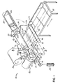
FIG. 1 is a perspective view showing an exemplary roll packing apparatus according to the principles of the present invention; -
FIG. 2 shows detail of the mandrel and compression roller of the apparatus ofFIG. 1 , where an in-fed material is being compressed between the mandrel and compression roller; -
FIG. 3 shows a cross-sectional view of the mandrel of the present invention, taken along line 3-3, showing the collapsed state of the mandrel in solid lines and the expanded state of the mandrel in dashed lines; -
FIG. 4A is a partial side-view of the apparatus ofFIG. 1 , depicting the start of a winding operation with an expanded mandrel; -
FIG. 4B shows the partial side-view of the apparatus ofFIG. 1 , depicting a partially wound roll on the expanded mandrel; -
FIG 4C shows the partial side-view of the apparatus ofFIG. 1 , depicting a fully wound roll and the mandrel in its collapsed state; -
FIG. 5 is an elevational view of another exemplary roll packing apparatus of the present invention; -
FIG. 6 is an elevational view of the roll packing apparatus ofFIG. 5 depicting a spring assembly being fed between precompression rollers and directed to the mandrel; -
FIG. 7 is an elevational view of the roll packing apparatus ofFIG. 5 depicting a fully wound roll of spring assemblies on the mandrel; -
FIG. 8 is an elevational view of the roll packing apparatus ofFIG. 5 depicting a finished roll of spring assemblies in position against the fixed compression roller after a gluing step; -
FIG. 9 is a plan view of the roll packing apparatus of the present invention, further including a finished roll manipulator, a pallet magazine, and a finished roll palletizer. - An apparatus and method are provided for roll packing compressible materials in a simple and efficient manner without damaging the materials, and wherein the materials can be stored and shipped in a compact state. The present invention may be described and understood by a description of an exemplary apparatus.
- With reference to
FIG. 1 , there is shown an illustration of one embodiment ofroll packing apparatus 10 incorporating the principles of the present invention. Theapparatus 10 includes acollapsible mandrel 12 for receiving in-fedmaterials 14 and winding them into a roll. Themandrel 12 is fixed to ashaft 16 that is driven at afirst end 18 by a driving mechanism, forexample motor 20 andgearbox 22 connected to theshaft 16. The invention further includes acompression roller 24, which is located proximate themandrel 12 and which is fixed to acompression roller shaft 26 that is substantially parallel to themandrel shaft 16. Thus, the rotational axis ofmandrel 12 is substantially parallel to the rotational axis ofcompression roller 24. Thecompression roller 24 is adjustable such as by means of anactuator 28 fixed to theroller shaft 26 whereby the spacing 30 (seeFIGS. 2 and 4A ) between thecompression roller 24 and themandrel 12 may be adjusted to vary or maintain the amount of compression on the in-fedmaterials 14. A feed table 32 located upstream of themandrel 12 andcompression roller 24 directs in-fedcompressible materials 14 between themandrel 12 andcompression roller 24 as thematerial 14 is wound upon themandrel 12. In one example of the present invention, not shown, the feed table 32 includes a jig plate to ensure proper alignment of the in-fedmaterials 14 with respect to themandrel 12 andcompression roller 24. Adisc brake 34 may be attached to theroller shaft 26 to control rotation of thecompression roller 24. - The
apparatus 10 further includes a packingmaterial dispenser 36 which supplies packingmaterial 38, such as paper, plastic or fiber material, to asurface 40 of the in-fedcompressible materials 14 as they are fed through themandrel 12 andcompression roller 24. The packing material is then wound with the compressed in-fed material to create a barrier layer between successive turns of the rolled material. In this manner, the barrier layer protects successive layers of in-fed material such as foam and prevents adhesion of the successive layers. The packingmaterial dispenser 36 may further include aguide roller 42,pinch rollers tension roller 48 to aid in directingpacking material 38 to the in-fedcompressible material 14 and also to maintain proper tension and alignment of the packingmaterial 38. - A bearing
plate 50 is located at asecond end 52 of themandrel shaft 16, opposite thedrive motor 20, and is movable to expose an end of themandrel 12 so that a finished roll ofmaterial 54 may be removed from themandrel 12. The apparatus further includes aroll handler 58 for facilitating easy removal of the finished rolls 54. In the exemplary embodiment ofFIG. 1 , theroll handler 58 is a trough-shaped cradle that is pivotally connected to a support (not shown) and can be placed in a first position near the end of themandrel 12 for receiving a finished roll ofmaterial 54. A roll pusher 60 associated with themandrel 12 aids in removing afinished roll 54 from the collapsedmandrel 12 onto theroll handler 58. Theroll handler 58 may then be placed in a second position (shown in phantom) to permit operators to subsequently remove theroll 54 from themachine 10. - As depicted more fully in
FIGS. 2 and 3 , thecollapsible mandrel 12 includes a series ofelongated plates 62 attached to themandrel shaft 16 and positioned about theshaft 16 in an overlapping arrangement to create a substantiallytubular surface 64 along the length of theshaft 16. Theplates 62 are slidably connected to theshaft 16 and move toward or away from theshaft 16 along radially extendingpaths 66 to increase or decrease thediameter 67 of thetubular surface 64 formed by the overlappingplates 62.Rods 68 connected to eachplate 62 engage a cam 70 attached to theshaft 16, whereby rotational operation of the cam 70 causes theplates 62 to move either toward or away from theshaft 16 to correspondingly collapse or expand themandrel diameter 67. - Referring to
FIGS. 4A-4C , the method of the present invention, as it relates to operation of theexemplary apparatus 10 ofFIGS. 1-3 , will be described. The spacing 30 between themandrel 12 andcompression roller 24 is adjusted to provide a desired amount of compression in the in-fedcompressible material 14.Packing material 38 from the packingmaterial dispenser 36 is fed through theguide roller 42,pinch rollers tension roller 48 and then directed between thecompression roller 24 andmandrel 12 while themandrel 12 is turned to wind an initial length of packingmaterial 38 upon themandrel 12, as depicted inFIG 4A . In-fedcompressible material 14, which is supported on feed table 32, is directed between themandrel 12 andcompression roller 24. The motor 20 (FIG. 1 ) is started and themandrel 12 rotates to wind up the in-fedcompressible material 14 and packingmaterial 38 as it is compressed between themandrel 12 andcompression roller 24. The actuator 28 (FIG. 1 ) attached to thecompression roller shaft 26 may be operated to vary thespacing 30 between themandrel 12 andcompression roller 24 as theroll 54 gets bigger, as can be seen inFIG. 4B , to maintain uniform compression in theroll 54. When a sufficient amount ofcompressible material 14 has been wound upon themandrel 12, themotor 20 is stopped. Thefinished roll 54 is secured, for example, with tape, straps, or other suitable material, and bearing plate 50 (FIG. 1 ) is moved to expose an end of themandrel 12. Themandrel 12 is then collapsed, as depicted inFIG. 4C , so that thefinished roll 54 may be removed from themandrel 12 under the operation of the roll pusher 60 (FIG. 1 ). The roll pusher 60 pushes thefinished roll 54 into the roll handler 58 (FIG. 1 ) and theroll handler 58 then pivots to a second position so that operators can maneuver thefinished roll 54 away from themachine 10. - With reference to
FIG. 5 , there is shown an illustration of another exemplaryroll packing apparatus 110 incorporating the principles of the present invention. Theapparatus 110 includes a radiallycollapsible mandrel 112 for receiving in-fedspring assemblies 114 and winding them into a roll.Collapsible mandrel 112 is attached to apivot arm 116 havingpivot axis 118. Thecollapsible mandrel 112 has arotational axis 120 which is substantially parallel to thepivot axis 118. A fixedcompression roller 122 is located proximate themandrel 112 and has arotational axis 124 substantially parallel to therotational axis 120 of themandrel 112. -
Pivot arm 116 pivots aboutpivot axis 118 to position themandrel 112 relative to the fixedcompression roller 122 to compress in-fedspring assemblies 114 in a controllable manner as they are wound upon themandrel 112. Theapparatus 110 further includes aprecompression guide roller 126 upstream of themandrel 112 for receiving in-fedspring assemblies 114 and directing them toward themandrel 112 and fixedcompression roller 122. Theprecompression guide roller 126 provides a gradual initial compression of thespring assemblies 114 prior to being further compressed between themandrel 112 and fixedcompression roller 122, as illustrated inFIG. 6 . Advantageously, theprecompression guide roller 126 provides precompression to springassemblies 114 having tall or small diameter springs which are susceptible to shifting that would otherwise occur if they were subjected to rapid compression by being directed to the fixedcompression roller 122 andmandrel 112 without any precompression. - A feed table 128 upstream of the
precompression guide roller 126 supports in-fedspring assemblies 114 and directs them toward theprecompression guide roller 126. The feed table 128 includes a plurality ofrollers 130 disposed on asupport surface 132 of the feed table 128 to transportspring assemblies 114 toward theprecompression guide roller 126. The feed table 128 further includes aprecompression conveyer 134 which operates in conjunction with theprecompression guide roller 126 toprecompress spring assemblies 114 and automatically feed thespring assemblies 114 between themandrel 112 and fixedcompression roller 122. Moving side guides 136 on the feed table 128 aid in automatically in-feeding thespring assemblies 114 and ensure proper spacing between the in-fedspring assemblies 114. The feed table 128 includes aframe 138 havingcasters 140 located at the bottom of theframe 138 to allow movement of the feed table 128 toward and away from theprecompression guide roller 126. Thecasters 140 are positioned onguide rails 142 which control the path of the feed table 128. Drive motors (not shown) coupled to thefeed table frame 138, thefeed table rollers 130, the side guides 136, and theprecompression conveyor 134 provide the motive forces to movespring assemblies 114 along the feed table 128 and between theprecompression roller 126 andconveyor 134 to be directed to themandrel 112 for winding. - The
apparatus 110 includes one or morepacking material dispensers 152 positioned near themandrel 112 for receiving and dispensingpacking material 154, such as paper, foil, or various fabric materials, to the in-fedspring assemblies 114 as they are being wound upon themandrel 112. Each packingmaterial dispenser 152 has associated packingmaterial feed rollers 156 and atension compensator 158 for feeding and directingpacking material 154 from thedispenser 152 toward themandrel 112 and fixedcompression roller 122. The packing material feed rollers may be supported on pneumatic cylinders whereby the position of the feed rollers may be adjusted. Asspring assemblies 114 are directed through theprecompression guide roller 126 toward themandrel 112 and fixedcompression roller 122, packingmaterial 154 is pushed toward themandrel 112 by thespring assemblies 114. Themandrel 112 includes a vacuum system which draws the packingmaterial 154 toward asurface 160 of themandrel 112 so that it is wound tightly upon themandrel 112 prior to compressing and winding ofspring assemblies 114 upon themandrel 112. Referring further toFIG. 6 , asspring assemblies 114 are wound upon themandrel 112,pivot arm 116 pivots aboutpivot axis 118 to move themandrel 112 away from the fixedcompression roller 122 in a controlled manner so thatsuccessive spring assemblies 114 are uniformly compressed and rolled upon themandrel 112. - The
apparatus 110 further includes an automated cutting and gluingunit 162 in line between the packingmaterial dispensers 152 and themandrel 112. The cutting and gluingunit 162 automatically cuts thepacking material 154 near the end of afinished roll 164 ofcompressed spring assemblies 114 and applies adhesive to a final layer of packingmaterial 154, which is wound to secure thefinished roll 164. Referring toFIG. 7 ,pivot arm 116 holds thefinished roll 164, still on themandrel 112, against the fixedcompression roller 122 to provide pressure to the end of the final layer of packingmaterial 154 until the adhesive has cured and thefinished roll 164 may be removed from themandrel 112. Referring toFIG. 8 ,pivot arm 116 rotates to move thefinished roll 164 away from the fixedcompression roller 122 and places thefinished roll 164 on afinished roll support 166. At this point, themandrel 112 may be collapsed radially inward to release thefinished roll 164 and aroll pusher 168 is activated to push thefinished roll 164 off themandrel 112 along thefinished roll support 166. - Referring to
FIG. 9 , theapparatus 110 further includes acontroller 170 connected to the various drive motors and to sensors positioned at various locations on theapparatus 110 for controlling the automated roll packing ofspring assemblies 114, as described above. Thecontroller 170 is also configured to count the number ofspring assemblies 114 that have been wound upon themandrel 112. Apower supply 172 provides electrical current to theapparatus 110 and its components. While theapparatus 110 is designed for completely automated roll packing of spring assemblies, it can also be used without an automated feed table 128 when manual feeding ofspring assemblies 114 is desired. As more clearly shown inFIG. 5 , theroll packing apparatus 110 includes aframe structure 174 for supporting the components described above. Theframe structure 174 may be configured to have a modular design, wherein various sections of theapparatus 110 may be separately assembled and disassembled to facilitate transportation and assembly of theapparatus 110. - Referring to
FIG. 9 , anautomated system 180 for providing roll packedspring assemblies 114 includes aroll packing apparatus 110, as described above, and further includes afinished roll manipulator 182 which receives finished rolls 164 ofspring assemblies 114 from thefinished roll support 166 and moves them to afinished roll palletizer 184. Thefinished roll palletizer 184 includes apallet magazine 186, aroll wrapping machine 188 for wrappingfinished rolls 164 for shipment and storage, and aconveyor 190. - In one exemplary embodiment, a
roll packing apparatus 110 according to the principles of the present invention has a radiallycollapsible mandrel 112 having a diameter of about 300 mm. Theexemplary apparatus 110 can receive rolls of packingmaterial 154 up to about 2100 mm in width and about 1000 mm in diameter, and can accommodatespring assemblies 114 up to about 200-mm wide and about 240-mm high. Theexemplary apparatus 110 can producefinished rolls 164 ofspring assemblies 114 of up to about 650 mm in diameter, each roll containing 10-12spring assemblies 114, at a rate of about 12-20 rolls per hour. - While the present invention has been illustrated by the description of an embodiment thereof, and while the embodiment has been described in considerable detail, it is not intended to restrict or in any way limit the scope of the appended claims to such detail. Additional advantages and modifications will readily appear to those skilled in the art. The invention in its broader aspects is therefore not limited to the specific details, representative apparatus and method and illustrative examples shown and described. Accordingly, departures may be made from such details without departing from the scope of applicant's general inventive concept.
Claims (16)
- An apparatus (10) for roll packing compressible material (14), comprising:an elongated, radially collapsible mandrel (12), said mandrel having a rotational axis along its length, whereby compressible material may be wound upon said mandrel by rotating said mandrel, said mandrel comprising:a elongate shaft (16),a plurality of elongated plates (62) connected to said shaft and arranged about said shaft to form a substantially tubular surface (64) wherein each plate overlaps a longitudinal edge of an adjacent plate, each plate being movable along a direction radial to the rotational axis of said mandrel to increase or decrease the diameter (67) of said surface formed by said overlapping plates, characterised bya cam (70) disposed on said shaft (16) and operatively connect to said plurality of plates (62), said cam configured to move said plates toward or away from said axis of said mandrel (12) along paths (66) extending radially from said shaft when said cam is rotated, such that said surface formed by said overlapping plates increases or decreases in diameter under the operation of said cam;a compression roller (24) operatively associated with said mandrel (12) and spaced therefrom and having a rotational axis substantially parallel to said rotational axis of said mandrel;said mandrel (12) and said compression roller (24) configured to vary the spacing therebetween, whereby compressible material (14) may be compressed between said mandrel and said compression roller as it is wound upon said mandrel; anda roll pusher (60) proximate said mandrel (12) and configured to engage a finished roll of material (54) on said mandrel and push the roll of said mandrel.
- The apparatus of claim 1, further comprising:a pivot arm (116) having a pivot axis (118) about which said pivot arm may be rotated; said mandrel (112) rotationally supported on said pivot arm whereby said mandrel may be moved relative to said compression roller (122) to vary the spacing therebetween.
- The apparatus of either claim 1 or claim 2, wherein said compression roller (24) is configured for movement relative to said mandrel (12) to vary the spacing
therebetween. - The apparatus of any preceding claim, further comprising:a precompression guide roller (126) proximate said mandrel for receiving in-fed compressible material (114) and directing the compressible material toward said mandrel (112) while simultaneously compressing the compressible material; anda feed table (128) upstream of said precompression guide roller (126) for supporting the in-fed compressible material and directing the compressible material toward said precompression guide roller.
- The apparatus of any preceding claim, further comprising:a feed table (128) upstream of said mandrel (112) for supporting the in-fed compressible material (114) and directing the compressible material toward said mandrel.
- The apparatus of any preceding claim, further comprising:at least one packing material dispenser (152) proximate said mandrel (112) for receiving and dispensing packing material to the compressible material as it is wound upon said mandrel.
- The apparatus of claim 6, further comprising:at least one feed roller (156) associated with said packing material dispenser (152) to direct the packing material from said dispenser to the compressible material as it is wound upon said mandrel.
- The apparatus of either claim 6 or claim 7, further comprising:a vacuum system operatively associated with said mandrel, the vacuum system operating to draw packing material toward said mandrel (112)and facilitate winding of the packing material (154) on said mandrel.
- The apparatus of any one of claims 6 to 8, further comprising:a cutting and gluing module (162) upstream of said mandrel (112) and constructed to cut the packing material (154) near the end of a finished roll (164) and to apply adhesive to the end of the packing material to secure the finished roll.
- The apparatus of any preceding claim, further comprising:a roll handler (58) proximate an end of said mandrel (12) and configured to receive a roll of material from said mandrel and reposition the roll relative to the apparatus (10) for subsequent processing.
- The apparatus of claim 10, wherein said roll handler (58) is an elongate, trough-shaped cradle pivotally mounted at a first end to a support, whereby the cradle may be placed in a first position to be substantially axially aligned with the mandrel (12) to receive a finished roll (54) from the second end of the mandrel, and whereby the cradle may be pivoted to a second position to permit subsequent handling of the finished roll.
- The apparatus of any preceding claim, further comprising:a finished roll manipulator (182); anda finished roll palletizer (184), said finished roll palletizer including:a pallet magazine (186); anda roll wrapping machine (188).
- The apparatus of any preceding claim, further comprising a support bearing (50) located at a distal end of said mandrel, said support bearing being movable to expose said end of said mandrel (12) to allow removal of a finished roll of material (54) from said mandrel.
- A method of roll packing compressible material (14) in a roll packing machine (10) having a radially collapsible mandrel (12) and a compression roller (24) proximate the mandrel comprising an elongated shaft (16) having a rotational axis along its length, a plurality of elongated plates (62) connected to the shaft and arranged about said shaft to form a substantially tubular surface (64), wherein each plate overlaps a longitudinal edge of an adjacent plate, each plate being movable along a direction radial to the rotational axis of said shaft to increase or decrease the diameter (67) of said surface formed by said overlapping plates and a cam (70) disposed on the shaft (16) and operatively connected to the plurality of plates (62), the cam configured to move the plates towards or away from the axis of the shaft along paths (66) extending radially from the shaft when the cam is rotated, such that the surface formed by the overlapping plates increases or decreases in diameter under the operation of the cam, the method comprising the steps of:providing the mandrel (12) in a non-collapsed position;adjusting the spacing between the compression roller (24) and the mandrel (12) to obtain a desired compression of the compressible material;directing compressible material (14) between the mandrel and the compression roller such that compressible material can be wound upon the mandrel (12) by rotating the mandrel;rotating the mandrel (12) to wind the compressible material onto the mandrel;stopping rotation of the mandrel (12) when a desired quantity of compressible material has been wound onto the mandrel;rotating the cam (70) to move the mandrel from the non-collapsed position to a collapsed position to release a roll from an outer surface of the mandrel; andremoving the roll of compressible material (54) from the mandrel.
- The method of claim 14, wherein the roll packing machine further includes a packing material dispenser (152), the method further comprising:applying packing material to the compressible material as it is wound upon the mandrel
- The method of either claim 14 or 15, further comprising:securing the roll packed compressible material (54), prior removal from the mandrel (12), to prevent unrolling.
Applications Claiming Priority (7)
| Application Number | Priority Date | Filing Date | Title |
|---|---|---|---|
| US09/986,227 US20030074863A1 (en) | 2001-10-22 | 2001-10-22 | Method for roll packing foam cores |
| US10/066,905 US6640520B2 (en) | 2001-10-22 | 2001-10-22 | Apparatus and method for roll packing compressible materials |
| US66905 | 2001-10-22 | ||
| US986227 | 2001-10-22 | ||
| US34744901P | 2001-11-01 | 2001-11-01 | |
| US347449P | 2001-11-01 | ||
| PCT/US2002/033123 WO2003035482A1 (en) | 2001-10-22 | 2002-10-17 | Apparatus and method for roll packing compressible materials |
Publications (3)
| Publication Number | Publication Date |
|---|---|
| EP1438232A1 EP1438232A1 (en) | 2004-07-21 |
| EP1438232A4 EP1438232A4 (en) | 2007-10-03 |
| EP1438232B1 true EP1438232B1 (en) | 2009-02-25 |
Family
ID=27371059
Family Applications (1)
| Application Number | Title | Priority Date | Filing Date |
|---|---|---|---|
| EP02802152A Expired - Lifetime EP1438232B1 (en) | 2001-10-22 | 2002-10-17 | Apparatus and method for roll packing compressible materials |
Country Status (5)
| Country | Link |
|---|---|
| EP (1) | EP1438232B1 (en) |
| CN (1) | CN1310803C (en) |
| AT (1) | ATE423735T1 (en) |
| DE (1) | DE60231315D1 (en) |
| WO (1) | WO2003035482A1 (en) |
Cited By (1)
| Publication number | Priority date | Publication date | Assignee | Title |
|---|---|---|---|---|
| IT202100020711A1 (en) * | 2021-08-02 | 2023-02-02 | Materassificio Montalese S P A | SYSTEM AND METHOD OF CONDITIONING USED MATTRESSES |
Families Citing this family (16)
| Publication number | Priority date | Publication date | Assignee | Title |
|---|---|---|---|---|
| ITMI20060118A1 (en) * | 2006-01-25 | 2007-07-26 | Brosiomeccanica S R L | ROLLING MACHINE FOR PILLOWS OR OTHER SOFT LONG-SIDE PRODUCTS |
| US8272192B2 (en) * | 2009-11-02 | 2012-09-25 | L & P Property Management Company | Spring-roll-pack opener |
| CN102862714B (en) * | 2012-09-26 | 2015-01-07 | 全越 | Self-service full-automatic paper tube filling method and self-service full-automatic paper tube filling mechanism |
| CN103848017B (en) * | 2014-03-20 | 2015-08-19 | 于振中 | The stacking encasement all-in-one machine of a kind of carpet shaping |
| AT515660B1 (en) * | 2014-07-11 | 2015-11-15 | Resch Horst Dipl Ing | Device for producing a supply roll of a compressed sealing strip |
| CN104590639B (en) * | 2015-01-20 | 2017-04-05 | 安庆市恒昌机械制造有限责任公司 | Tire cotton shifts system for compacting |
| CN105691770B (en) * | 2016-04-18 | 2018-01-26 | 湖州师范学院 | Yoga mat clamping automatic bending packaging equipment |
| CN105775262B (en) * | 2016-04-18 | 2018-06-29 | 湖州师范学院 | Yoga mat clamps bending and rolling device |
| CN105775819B (en) * | 2016-04-18 | 2019-02-19 | 浙江巨祥智能科技有限公司 | Yoga mat twists packaging facilities automatically |
| CN105691774B (en) * | 2016-04-18 | 2018-02-09 | 湖州师范学院 | Yoga mat bushing type twists packaging facilities automatically |
| CN106081274A (en) * | 2016-07-27 | 2016-11-09 | 中国科学院光电研究院 | Packing device |
| CN109592146A (en) * | 2019-01-24 | 2019-04-09 | 衡水大众橡塑有限公司 | A kind of rubber fastening band spooling packing apparatus |
| CN111269049B (en) * | 2020-03-06 | 2021-12-17 | 佳木斯恺乐农业生物工程有限公司 | Organic fertilizer processed by agricultural wastes and processing device and processing method thereof |
| CN111591535B (en) * | 2020-06-09 | 2021-11-26 | 杭州赞恩日化有限公司 | Mask and processing system and processing method thereof |
| CN113002899B (en) * | 2021-03-30 | 2024-04-05 | 安徽省伊贝雅纺织有限公司 | Rolling packing apparatus is used in towel production |
| CN113911483B (en) * | 2021-10-28 | 2023-05-09 | 宁夏大斌家纺科技有限公司 | Automatic packaging device based on spinning cloth roll |
Family Cites Families (12)
| Publication number | Priority date | Publication date | Assignee | Title |
|---|---|---|---|---|
| US2114008A (en) * | 1933-10-05 | 1938-04-12 | Moore Co | Spring-packing machine |
| US2668405A (en) * | 1951-01-29 | 1954-02-09 | Meridan Corp | Mattress winding and wrapping machine |
| US4385478A (en) * | 1980-11-06 | 1983-05-31 | Hosiery Corporation Of America, Inc. | Folding and packing machine for pantyhose |
| CH652379A5 (en) * | 1981-09-18 | 1985-11-15 | Ferag Ag | WRAPPING BODY FOR REWINDING CONTINUOUSLY ARRANGED AREAS, ESPECIALLY PRINTED PRODUCTS IN DANDEL INFORMATION. |
| GB2121008B (en) * | 1982-05-22 | 1986-07-30 | Silentnight Holdings Plc | Spring packing machine |
| US4711067A (en) | 1984-02-03 | 1987-12-08 | Giuliano Magni | Method of packaging a single mattress to a small size to be conveniently carried |
| ATE44939T1 (en) * | 1986-04-30 | 1989-08-15 | Ferag Ag | METHOD AND DEVICE FOR PROCESSING FLAT PRODUCTS, IN PARTICULAR PRINTING PRODUCTS. |
| NL9002246A (en) * | 1990-08-28 | 1992-03-16 | Ferag Ag | METHOD FOR PROCESSING PRINTING AVAILABLE IN A SCALE INFORMATION |
| EP0618139B1 (en) * | 1993-04-01 | 1997-06-04 | Ferag AG | Device for handling printed products |
| US5765343A (en) * | 1995-10-20 | 1998-06-16 | Whittaker; Dale | Individual dental floss packaging method and apparatus |
| US6098378A (en) * | 1998-10-02 | 2000-08-08 | Wyatt; Curtis | Method of packaging a single mattress to a small size to be conveniently carried |
| EP1970309A1 (en) * | 1999-09-15 | 2008-09-17 | L&P Property Management Company | Method of packaging a spring unit |
-
2002
- 2002-10-17 WO PCT/US2002/033123 patent/WO2003035482A1/en not_active Ceased
- 2002-10-17 AT AT02802152T patent/ATE423735T1/en not_active IP Right Cessation
- 2002-10-17 DE DE60231315T patent/DE60231315D1/en not_active Expired - Lifetime
- 2002-10-17 CN CNB028199022A patent/CN1310803C/en not_active Expired - Fee Related
- 2002-10-17 EP EP02802152A patent/EP1438232B1/en not_active Expired - Lifetime
Cited By (1)
| Publication number | Priority date | Publication date | Assignee | Title |
|---|---|---|---|---|
| IT202100020711A1 (en) * | 2021-08-02 | 2023-02-02 | Materassificio Montalese S P A | SYSTEM AND METHOD OF CONDITIONING USED MATTRESSES |
Also Published As
| Publication number | Publication date |
|---|---|
| CN1310803C (en) | 2007-04-18 |
| ATE423735T1 (en) | 2009-03-15 |
| WO2003035482A1 (en) | 2003-05-01 |
| EP1438232A4 (en) | 2007-10-03 |
| DE60231315D1 (en) | 2009-04-09 |
| CN1608018A (en) | 2005-04-20 |
| EP1438232A1 (en) | 2004-07-21 |
Similar Documents
| Publication | Publication Date | Title |
|---|---|---|
| EP1438232A1 (en) | Apparatus and method for roll packing compressible materials | |
| EP4008638B1 (en) | Machine and method for stabilising palletised loads | |
| KR102098091B1 (en) | A Wire Autobinding Packaging Device | |
| EP1400450B1 (en) | Continuous banding system for wrapping an elongated article such as a stack of interfolded paper towels | |
| US6810643B1 (en) | Method of roll packing compressible materials | |
| EP4091947B1 (en) | Machine for stabilising palletised loads with tensioning fins | |
| US12246509B2 (en) | Coiler for a dunnage conversion machine and method for coiling a strip of dunnage | |
| JPS58125553A (en) | Turret type winder winding sheet-shaped substance onto roll and its method | |
| US6640520B2 (en) | Apparatus and method for roll packing compressible materials | |
| CN101970321A (en) | Stretch film winder | |
| CA2125744C (en) | Apparatus for winding stiffened coreless rolls and method | |
| US11987406B2 (en) | Machine for stabilising palletised loads with reel change system | |
| US6892448B2 (en) | Automated roll packing apparatus | |
| US20030074863A1 (en) | Method for roll packing foam cores | |
| EP0254458A2 (en) | Apparatus and method for wrapping rolls of pressure sensitive sheet material | |
| EP1306335B1 (en) | Re-reeling machine for plastic film or the like | |
| RU2781647C2 (en) | Machine and method for production of coreless rolls of material intended for use in form of sheet, in particular aluminum one, intended for use for food products | |
| JP4668011B2 (en) | Packaging method and packaging machine | |
| JPH08151008A (en) | Simple wrapping machine for scrolls |
Legal Events
| Date | Code | Title | Description |
|---|---|---|---|
| PUAI | Public reference made under article 153(3) epc to a published international application that has entered the european phase |
Free format text: ORIGINAL CODE: 0009012 |
|
| 17P | Request for examination filed |
Effective date: 20040303 |
|
| AK | Designated contracting states |
Kind code of ref document: A1 Designated state(s): AT BE BG CH CY CZ DE DK EE ES FI FR GB GR IE IT LI LU MC NL PT SE SK TR |
|
| AX | Request for extension of the european patent |
Extension state: AL LT LV MK RO SI |
|
| A4 | Supplementary search report drawn up and despatched |
Effective date: 20070903 |
|
| 17Q | First examination report despatched |
Effective date: 20080131 |
|
| GRAP | Despatch of communication of intention to grant a patent |
Free format text: ORIGINAL CODE: EPIDOSNIGR1 |
|
| GRAS | Grant fee paid |
Free format text: ORIGINAL CODE: EPIDOSNIGR3 |
|
| GRAA | (expected) grant |
Free format text: ORIGINAL CODE: 0009210 |
|
| AK | Designated contracting states |
Kind code of ref document: B1 Designated state(s): AT BE BG CH CY CZ DE DK EE ES FI FR GB GR IE IT LI LU MC NL PT SE SK TR |
|
| REG | Reference to a national code |
Ref country code: GB Ref legal event code: FG4D |
|
| REG | Reference to a national code |
Ref country code: CH Ref legal event code: EP |
|
| REG | Reference to a national code |
Ref country code: IE Ref legal event code: FG4D |
|
| REF | Corresponds to: |
Ref document number: 60231315 Country of ref document: DE Date of ref document: 20090409 Kind code of ref document: P |
|
| REG | Reference to a national code |
Ref country code: SE Ref legal event code: TRGR |
|
| PG25 | Lapsed in a contracting state [announced via postgrant information from national office to epo] |
Ref country code: FI Free format text: LAPSE BECAUSE OF FAILURE TO SUBMIT A TRANSLATION OF THE DESCRIPTION OR TO PAY THE FEE WITHIN THE PRESCRIBED TIME-LIMIT Effective date: 20090225 Ref country code: NL Free format text: LAPSE BECAUSE OF FAILURE TO SUBMIT A TRANSLATION OF THE DESCRIPTION OR TO PAY THE FEE WITHIN THE PRESCRIBED TIME-LIMIT Effective date: 20090225 |
|
| NLV1 | Nl: lapsed or annulled due to failure to fulfill the requirements of art. 29p and 29m of the patents act | ||
| PG25 | Lapsed in a contracting state [announced via postgrant information from national office to epo] |
Ref country code: AT Free format text: LAPSE BECAUSE OF FAILURE TO SUBMIT A TRANSLATION OF THE DESCRIPTION OR TO PAY THE FEE WITHIN THE PRESCRIBED TIME-LIMIT Effective date: 20090225 |
|
| PG25 | Lapsed in a contracting state [announced via postgrant information from national office to epo] |
Ref country code: BE Free format text: LAPSE BECAUSE OF FAILURE TO SUBMIT A TRANSLATION OF THE DESCRIPTION OR TO PAY THE FEE WITHIN THE PRESCRIBED TIME-LIMIT Effective date: 20090225 |
|
| PG25 | Lapsed in a contracting state [announced via postgrant information from national office to epo] |
Ref country code: PT Free format text: LAPSE BECAUSE OF FAILURE TO SUBMIT A TRANSLATION OF THE DESCRIPTION OR TO PAY THE FEE WITHIN THE PRESCRIBED TIME-LIMIT Effective date: 20090812 Ref country code: ES Free format text: LAPSE BECAUSE OF FAILURE TO SUBMIT A TRANSLATION OF THE DESCRIPTION OR TO PAY THE FEE WITHIN THE PRESCRIBED TIME-LIMIT Effective date: 20090605 Ref country code: EE Free format text: LAPSE BECAUSE OF FAILURE TO SUBMIT A TRANSLATION OF THE DESCRIPTION OR TO PAY THE FEE WITHIN THE PRESCRIBED TIME-LIMIT Effective date: 20090225 Ref country code: DK Free format text: LAPSE BECAUSE OF FAILURE TO SUBMIT A TRANSLATION OF THE DESCRIPTION OR TO PAY THE FEE WITHIN THE PRESCRIBED TIME-LIMIT Effective date: 20090225 Ref country code: CZ Free format text: LAPSE BECAUSE OF FAILURE TO SUBMIT A TRANSLATION OF THE DESCRIPTION OR TO PAY THE FEE WITHIN THE PRESCRIBED TIME-LIMIT Effective date: 20090225 |
|
| PG25 | Lapsed in a contracting state [announced via postgrant information from national office to epo] |
Ref country code: SK Free format text: LAPSE BECAUSE OF FAILURE TO SUBMIT A TRANSLATION OF THE DESCRIPTION OR TO PAY THE FEE WITHIN THE PRESCRIBED TIME-LIMIT Effective date: 20090225 |
|
| PLBE | No opposition filed within time limit |
Free format text: ORIGINAL CODE: 0009261 |
|
| STAA | Information on the status of an ep patent application or granted ep patent |
Free format text: STATUS: NO OPPOSITION FILED WITHIN TIME LIMIT |
|
| PG25 | Lapsed in a contracting state [announced via postgrant information from national office to epo] |
Ref country code: BG Free format text: LAPSE BECAUSE OF FAILURE TO SUBMIT A TRANSLATION OF THE DESCRIPTION OR TO PAY THE FEE WITHIN THE PRESCRIBED TIME-LIMIT Effective date: 20090525 |
|
| 26N | No opposition filed |
Effective date: 20091126 |
|
| PG25 | Lapsed in a contracting state [announced via postgrant information from national office to epo] |
Ref country code: MC Free format text: LAPSE BECAUSE OF NON-PAYMENT OF DUE FEES Effective date: 20091031 |
|
| REG | Reference to a national code |
Ref country code: CH Ref legal event code: PL |
|
| REG | Reference to a national code |
Ref country code: IE Ref legal event code: MM4A |
|
| REG | Reference to a national code |
Ref country code: FR Ref legal event code: ST Effective date: 20100630 |
|
| PG25 | Lapsed in a contracting state [announced via postgrant information from national office to epo] |
Ref country code: FR Free format text: LAPSE BECAUSE OF NON-PAYMENT OF DUE FEES Effective date: 20091102 |
|
| PG25 | Lapsed in a contracting state [announced via postgrant information from national office to epo] |
Ref country code: GR Free format text: LAPSE BECAUSE OF FAILURE TO SUBMIT A TRANSLATION OF THE DESCRIPTION OR TO PAY THE FEE WITHIN THE PRESCRIBED TIME-LIMIT Effective date: 20090526 Ref country code: IE Free format text: LAPSE BECAUSE OF NON-PAYMENT OF DUE FEES Effective date: 20091017 Ref country code: LI Free format text: LAPSE BECAUSE OF NON-PAYMENT OF DUE FEES Effective date: 20091031 Ref country code: CH Free format text: LAPSE BECAUSE OF NON-PAYMENT OF DUE FEES Effective date: 20091031 |
|
| PG25 | Lapsed in a contracting state [announced via postgrant information from national office to epo] |
Ref country code: LU Free format text: LAPSE BECAUSE OF NON-PAYMENT OF DUE FEES Effective date: 20091017 |
|
| PG25 | Lapsed in a contracting state [announced via postgrant information from national office to epo] |
Ref country code: TR Free format text: LAPSE BECAUSE OF FAILURE TO SUBMIT A TRANSLATION OF THE DESCRIPTION OR TO PAY THE FEE WITHIN THE PRESCRIBED TIME-LIMIT Effective date: 20090225 |
|
| PG25 | Lapsed in a contracting state [announced via postgrant information from national office to epo] |
Ref country code: CY Free format text: LAPSE BECAUSE OF FAILURE TO SUBMIT A TRANSLATION OF THE DESCRIPTION OR TO PAY THE FEE WITHIN THE PRESCRIBED TIME-LIMIT Effective date: 20090225 |
|
| PGFP | Annual fee paid to national office [announced via postgrant information from national office to epo] |
Ref country code: SE Payment date: 20181011 Year of fee payment: 17 Ref country code: DE Payment date: 20181002 Year of fee payment: 17 |
|
| PGFP | Annual fee paid to national office [announced via postgrant information from national office to epo] |
Ref country code: GB Payment date: 20181017 Year of fee payment: 17 Ref country code: IT Payment date: 20181018 Year of fee payment: 17 |
|
| REG | Reference to a national code |
Ref country code: DE Ref legal event code: R119 Ref document number: 60231315 Country of ref document: DE |
|
| PG25 | Lapsed in a contracting state [announced via postgrant information from national office to epo] |
Ref country code: DE Free format text: LAPSE BECAUSE OF NON-PAYMENT OF DUE FEES Effective date: 20200501 |
|
| PG25 | Lapsed in a contracting state [announced via postgrant information from national office to epo] |
Ref country code: SE Free format text: LAPSE BECAUSE OF NON-PAYMENT OF DUE FEES Effective date: 20191018 |
|
| GBPC | Gb: european patent ceased through non-payment of renewal fee |
Effective date: 20191017 |
|
| PG25 | Lapsed in a contracting state [announced via postgrant information from national office to epo] |
Ref country code: IT Free format text: LAPSE BECAUSE OF NON-PAYMENT OF DUE FEES Effective date: 20191017 Ref country code: GB Free format text: LAPSE BECAUSE OF NON-PAYMENT OF DUE FEES Effective date: 20191017 |