EP1437828A2 - Vorrichtung und Prozesse zur Linearisierung von Interaktionen zwischen Filtern - Google Patents
Vorrichtung und Prozesse zur Linearisierung von Interaktionen zwischen Filtern Download PDFInfo
- Publication number
- EP1437828A2 EP1437828A2 EP04000530A EP04000530A EP1437828A2 EP 1437828 A2 EP1437828 A2 EP 1437828A2 EP 04000530 A EP04000530 A EP 04000530A EP 04000530 A EP04000530 A EP 04000530A EP 1437828 A2 EP1437828 A2 EP 1437828A2
- Authority
- EP
- European Patent Office
- Prior art keywords
- filter
- cut
- boost
- matrix
- boost setting
- Prior art date
- Legal status (The legal status is an assumption and is not a legal conclusion. Google has not performed a legal analysis and makes no representation as to the accuracy of the status listed.)
- Granted
Links
- 238000000034 method Methods 0.000 title claims abstract description 124
- 230000003993 interaction Effects 0.000 title claims description 24
- 230000008569 process Effects 0.000 title description 33
- 239000011159 matrix material Substances 0.000 claims abstract description 122
- 238000012937 correction Methods 0.000 claims abstract description 49
- 230000004044 response Effects 0.000 claims description 107
- 238000009499 grossing Methods 0.000 claims description 10
- 238000004891 communication Methods 0.000 claims description 7
- 238000004590 computer program Methods 0.000 claims description 7
- 230000004936 stimulating effect Effects 0.000 claims 2
- 238000013461 design Methods 0.000 abstract description 9
- 230000000694 effects Effects 0.000 abstract description 7
- 230000006870 function Effects 0.000 description 10
- 230000001419 dependent effect Effects 0.000 description 9
- 230000000740 bleeding effect Effects 0.000 description 5
- 230000004048 modification Effects 0.000 description 5
- 238000012986 modification Methods 0.000 description 5
- 238000001914 filtration Methods 0.000 description 4
- 238000010420 art technique Methods 0.000 description 3
- 230000008859 change Effects 0.000 description 3
- 238000010586 diagram Methods 0.000 description 3
- 238000012886 linear function Methods 0.000 description 3
- 230000000737 periodic effect Effects 0.000 description 3
- 238000013459 approach Methods 0.000 description 2
- 238000000053 physical method Methods 0.000 description 2
- 238000007781 pre-processing Methods 0.000 description 2
- 238000012545 processing Methods 0.000 description 2
- 238000004088 simulation Methods 0.000 description 2
- 230000001629 suppression Effects 0.000 description 2
- 238000012546 transfer Methods 0.000 description 2
- 230000004913 activation Effects 0.000 description 1
- 239000000654 additive Substances 0.000 description 1
- 230000000996 additive effect Effects 0.000 description 1
- 230000002411 adverse Effects 0.000 description 1
- 230000008901 benefit Effects 0.000 description 1
- 230000005540 biological transmission Effects 0.000 description 1
- 238000004364 calculation method Methods 0.000 description 1
- 230000003247 decreasing effect Effects 0.000 description 1
- 238000002955 isolation Methods 0.000 description 1
- 230000007246 mechanism Effects 0.000 description 1
- 239000003607 modifier Substances 0.000 description 1
- 238000010606 normalization Methods 0.000 description 1
- 238000013139 quantization Methods 0.000 description 1
- 238000012360 testing method Methods 0.000 description 1
- 230000007704 transition Effects 0.000 description 1
- 239000013598 vector Substances 0.000 description 1
Images


Classifications
-
- H—ELECTRICITY
- H03—ELECTRONIC CIRCUITRY
- H03G—CONTROL OF AMPLIFICATION
- H03G5/00—Tone control or bandwidth control in amplifiers
- H03G5/005—Tone control or bandwidth control in amplifiers of digital signals
-
- H—ELECTRICITY
- H03—ELECTRONIC CIRCUITRY
- H03G—CONTROL OF AMPLIFICATION
- H03G5/00—Tone control or bandwidth control in amplifiers
- H03G5/02—Manually-operated control
- H03G5/025—Equalizers; Volume or gain control in limited frequency bands
Definitions
- the present invention relates, in general, to filtering devices. More specifically, the present invention is related to digital signal processing filters and/or analog filters.
- Filtering devices allow for direct selection or suppression of frequency components of electrical signals.
- Those having ordinary skill in the art will appreciate that, for any particular signal, techniques exist which allow the signal to be approximated by a weighted sum of periodic signals (e.g., sine waves and/or cosine waves which repeat themselves within defined time periods). Each periodic signal in the sum has a certain frequency (inversely related to the time period required for the signal to repeat).
- the weighted periodic signals which are summed to approximate the analog signal may be referred to as the "frequency components" of the signal.
- One type of filtering device is known in the art as a "graphic equalizer," since it graphically illustrates the selection or suppression of the various frequency components of a signal.
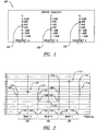
- FIG. 1 shows a front elevational view of a control panel of a conventional graphic equalizer 100.
- Graphic equalizer 100 typically incorporates a plurality of filters (passive or active, digital or analog) which amplify or attenuate electrical signals within discrete frequency passbands. Typically, such equalizers have each filter operated by a slider control related to each discrete passband.
- Graphic equalizer 100 operates on three frequency bands which are illustrated on a control panel face of graphic equalizer 100. The frequency bands upon which graphic equalizer 100 operates have center freque ncies, Frequency A , Frequency B , and Frequency c .
- Controls 102 associated with each frequency band, allow an operator (e.g., a human operator) to boost (i.e., amplify) the frequency band by up to 12 dB or cut ( i.e., attenuate) the frequency band by up to-12 dB.
- an operator e.g., a human operator
- boost i.e., amplify
- cut i.e., attenuate
- the frequency specific cutting or boosting performed by graphic equalizer 100 is typically achieved by filters centered on frequencies A, B, and C. Those having ordinary skill in the art will recognize that, ideally, each filter would uniformly cut or boost the components of the input signal which exist within passband (eg., 102, 104 and 106 of Figure 2) of each filter.
- FIG. 2 graphically shows magnitude responses of theoretical ideal filters which would preferably be used in conjunction with graphic equalizer 100.
- Each ideal filter provides a uniform response.
- a uniform response means that (a) the leftmost and rightmost edges 108, 110 of each passband (a band of frequencies which a filter is designed to let through, or "pass") are substantially vertical at or near the passband cutoff frequencies 116 defining the passband of each filter, and (b) the maximum amplitude 112 is substantially constant or flat in each passband so as to form sharp corner frequency response 114 therebetween.
- Figure 3 illustrates magnitude responses which are more representative of physically realizable, as opposed to ideal, filters.
- physically realizable filters tend to roll off gently rather than have sharp "corner" frequency responses (e.g., 114 of Figure 2).
- the fact that physically realizable filters do not provide sharp cutoff allows the energy from one frequency band of the graphic equalizer to bleed into the other frequency bands of the graphic equalizer. As can be seen, such interference tends to be additive, and thus gives rise to a resultant aggregate frequency response 120 which is not at all in keeping with the desired frequency response.
- Lane teaches generating a unique decoupling matrix by exciting a graphic equalizer using a series of test input vectors applied to a series of pre-stored decoupling matrices, and selecting as the decoupling matrix that matrix which generates the least overall error in graphic equalizer output. Thereafter, user specified graphic equalizer cut-boost input levels are subjected to the selected decoupling matrix to create corrected inputs. The graphic equalizer is then internally set to have these corrected inputs and allowed to operate.
- Lane tends to work with fixed Q value filters.
- a Q value is a number roughly indicating how well a "real world” filter approaches that of a theoretically ideal filter, such as how "sharp" the corner frequency response 114 will be.
- Lane's, and other related-art techniques also do not recognize that non-linearity of interactions between filters having fixed Q values varies dependent upon selected cut-boost levels. Accordingly, Lane's, and other related art techniques, do not show or suggest alleviating the non-linearity of interactions between filters by constructing filters having "linearizing" Q values which tend to linearize the interactions between filters. Accordingly, a need exists for a graphic equalizing filter system which utilizes linear techniques on filters having linearizing Q values.
- a method for use with equipment having filters includes but is not limited to multiplying a matrix having a specified cut-boost setting of a filter of a graphic equalizer by a correction matrix to create a matrix having a corrected cut-boost setting of the filter of the graphic equalizer; adjusting an actual cut-boost setting of the filter of the graphic equalizer to be substantially equal to the corrected cut-boost setting of the filter of the graphic equalizer; and configuring the filter to have a Q value substantially equal to a linearizing Q value.
- related systems include but are not limited to circuitry and/or programming for effecting the foregoing-referenced method embodiments; the circuitry and/or programming can be a combination of hardware, software, and/or firmware configured to effect the foregoing- referenced method embodiments depending upon the design choices of the system designer.
- a sound system includes but is not limited to at least one filter having a Q value configurable responsive to a defined cut-boost setting of the filter.
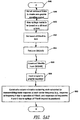
- Method step 500 depicts the start of the process.
- Method step 502 illustrates selecting filter Q values sufficient to approximately "linearize” the interactions between at least two bandpass filters (e.g. , the three filters A, B and C shown and described in relation to graphic equalizer 100). Selecting Q values sufficient to approximately "linearize” interactions between filters consists of choosing, for each individual filter considered in isolation, a series of Q values dependent upon preselected cut or boost levels (e.g., 2, 4, or 6 dB, etc.).
- the Q values are chosen such that, when each individual filter is excited by a signal, and the cut or boost level of each individual filter is then increased or decreased in a linear fashion, the magnitude response of each individual filter, when measured at some predefined point-of-linearity reference frequency, will increase or decrease in a linear fashion (e.g. , as shown and described in relation to Figure 4C).
- the point-of-linearity reference frequency is defined to be some distance (e.g., 1/3 of an octave) away from the center frequency of each individual filter (e.g., as shown and described in relation to Figure 4C).
- Method step 504 shows the operation of the creation of at least one correction matrix which has entries representative of obtained graphic equalizer outputs at the center frequencies of filters in the graphic equalizer (e.g., the three filters A, B, and C shown and described in relation to graphic equalizer 100), where the measured output is due to energy from one or more filters spilling beyond their passbands.
- the correction matrix has entries representative of the "bleeding" of energy of one or more filters outside of their prescribed filter bands.
- the outputs are obtained by numerical calculation or simulation. In another embodiment, the outputs are obtained by actual physical measurements of signals.
- Method step 506 depicts the operation of using the at least one correction matrix illustrated in method step 504 to adjust the specified cut-or boost levels of the individual filters such that, in the aggregate, the adjusted cut-boost levels give rise to a modification of the output of the graphic equalizer which approximates the output which would have been present if the cut boost levels had been set as specified and the cross-filter "bleeding" from the respective filters had not been present in the filter system.
- Method step 508 illustrates setting the Q value of each filter in the graphic equalizer to an appropriate "linearized” Q value.
- this is achieved by setting the Q value for each value dependent upon the just calculated "corrected" cut-boost value of each filter (e.g., that described in method step 506), which in one embodiment is achieved by a process substantially a nalogous to that described in relation to method step 502 (e.g., Qs are chosen for each filter based upon the corrected cut-boost value of each individual filter such that the response at the point of linearity varies linearly with the change from the specified cut boost level to the corrected cut boost level).
- the Q of each filter is chosen to be that associated with the user specified Q of each filter.
- Method step 509 illustrates the activation of the graphic equalizer, where the cut boost levels of the filters (e.g., the three filters A, B, and C shown and described in relation to graphic equalizer 100) have been set to the corrected cut boost levels described in relation to method step 508, and where the Q values of the filters have been set such that the individual responses of the filters in the graphic equalizer are linear at the defined point-of-linearity frequency.
- the cut boost levels of the filters e.g., the three filters A, B, and C shown and described in relation to graphic equalizer 100
- Method step 510 shows the end of the process.
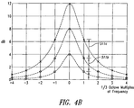
- Figure 4B shows a graph depicting the response curves of a filter when the cut-boost setting is adjusted in respective linear steps to 4, 8, and 12 dB of boost. Depicted is that for a filter with a constant Q value, the magnitude response levels at a distance of one-third an octave away from the center frequency of the filter do not change as a linear function of the setting. This can be seen in the graph from the fact that the cut-boost settings are changed in equal increments, but the responses at the one-third octave position differ 511 b and 511c by unequal amounts.
- Figure 4C depicts a graph illustrating the response curves of a filter wherein the Q values of a filter have been chosen dependent upon the specified cut-boost settings such that the magnitude response levels at one-third octave away from the center frequency of the filter have been mathematically "linearized.”
- the graph in Figure 4C constitutes one specific example of an implementation of the operations shown and described in relation to method step 502.
- the Q values have been chosen such that when the cut-boost settings are adjusted in respective linear steps to 4, 8, and 12 dB of boost with respect to center frequency f o , the magnitude response levels at one-third octave away from the center frequency of the filter do change as a linear function of the setting, which as can be seen in the graph from the fact that when the cut boost settings are changed in equal increments, the responses at the one-third octave position differ 505b and 505c by equal amounts.
- Figure 4D illustrates three tables which show that for each filter in the graphic equalizer (e.g., filters A, B and C of graphic equalizer 100), Q values are determined such that when the cut-boost levels of the filters are varied in a linear fashion the magnitude responses at some defined distance away from the center frequency (e.g., 1/3 octave from the center frequency) vary in a linear fashion.
- the tables in Figure 4D constitute one specific example of an implementation of the operations shown and described in relation to method step 502.
- Q values Q A (dB), Q B (dB), and Q C (dB) are respectively chosen, as a function of the cut-boost decibel settings, such that the responses of the individual filters at some predefined distance from the center frequencies vary linearly when the cut-boost settings are varied linearly.
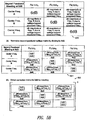
- FIG. 5A1-3 and 5B shown is a specific example of the generation of a correction matrix such as was shown and described in relation to method step 504.
- there are two main steps in the creation of a correction matrix (1) creation of a "spillage" matrix representing the "spillage,” or “bleeding,” of energy beyond the passband of one filter into the passband of one or more other filters, and (2) inversion of the spillage matrix.
- FIG. 5A1-3 depicted is a high-level logic flowchart showing a specific example of the creation of a spillage matrix based on a 6 dB setting of cut-boost controls of a graphic equalizer (e.g., graphic equalizer 100).
- Method step 630 shows the start of the process.
- Method step 632 illustrates that creation of the matrix column for Filter A involves first setting all of the cut-boost settings such that the output of the graphic equalizer at the center frequencies of the filters would be expected to be zero. As described herein, in one embodiment such settings are to 0 dB, rather than to maximum attenuation, because in one implementation the filters in graphic equalizer 100 are cascaded, and thus their transfer functions multiply.
- Method step 634 shows that, subsequent to setting the gain of the filters such that the output of the graphic equalizer at the center frequency of the filters would be expected to be zero, the fact that the spillage matrix is to be created based on a 6dB level is noted.
- Method step 636 depicts that, thereafter, the cut-boost level of the filter having center frequency A is set to 6 dB.
- Method step 638 illustrates that, thereafter, the Q A (6 dB), or the linearizing Q value of filter A, which is associated with a 6 dB setting of Filter A (e.g., such as shown and described in relation to Figure 5D) , is retrieved.
- Method step 640 shows that a filter having such Q A (6 dB) is subsequently constructed (e.g., computationally).
- Method step 642 illustrates that the graphic equalizer is excited with a signal (e.g., a "white noise" signal). Thereafter, method step 644 shows that the output magnitude of the graphic equalizer at the filter center frequencies are obtained (e.g., in one embodiment, via numerical simulation, and in another embodiment via actual physical measurement).
- a signal e.g., a "white noise” signal.
- any output obtained at center frequencies other than center frequency A (e.g., obtained at center frequencies B and C) will be due to the "bleeding,” or “spillage,” of energy of A beyond its passband (e.g., spillage as illustrated and described in relation to Figure 3).
- shown in method step 644 is that the column entries associated with center frequency A call out that the response at center frequency A is 6 dB, the response at center frequency B is due to the spillage of energy outside of A's passband, and the response at center frequency C is due to the spillage of energy outside of A's passband.
- FIG. 5A1-3 shown are processes used to construct the matrix columns associated with Filter B (e.g., method steps 646-660) and Filter C (e.g, method steps 662-674). Specifically, shown is that, with respect to the columns in the spillage matrix associated with filters having center frequencies B and C, processes substantially analogous to the processes used to construct the column for FilterA are used.
- a correction matrix is created from the spillage matrix shown by a two step process.
- the spillage matrix is normalized to generate a normalized matrix 621 by dividing the entries of the spillage matrix by the non-zero cut-boost settings utilized to generate the spillage matrix.
- the correction matrix 622 is obtained by inverting the normalized matrix 621. This correction matrix 622 may now be used as shown and described herein.
- Figures 6A and 6B show a specific example of how one embodiment uses the correction matrix to adjust the cut-boost settings of the individual filters to provide compensation such that the output of the graphic equalizer is "as if" no cross filter interference were present.
- a user e.g., a human user
- the cut boost level of Filter A to 2 dB
- the cut boost level of Filter B to -2 dB
- the cut boost level of Filter C to 6 dB.
- a column matrix 624 is created from the specified settings.
- the column matrix 624 is multiplied by the correction matrix 622, and that the resultant settings matrix 626 will be the original user specified settings plus or minus the aggregate adjustment necessary to make the output of the graphic equalizer function "as if"there were no cross filter interference present.
- the resultant matrix contains what are referred to herein as the corrected cut-boost settings 628 for Filter A , Filter B , and Filter C .
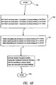
- Method step 720 shows the start of the process.
- Method step 722 depicts that the cut-boost settings of Filter A , Filter B , and Filter C are set to their respective corrected levels.
- method step 724 shows that the linearized Q values appropriate to the settings of Filter A , Filter B , and Filter C are obtained, and filters having such Q values are constructed.
- this is achieved by setting digital filter coefficients in the cascaded filters forming graphic equalizer 100 (see Figure 8), while in another embodiment discrete components of analog filters are adjusted to achieve the desired Q values.
- method step 726 illustrates that graphic equalizer 100 is activated.
- Method step 728 shows the end of the process.
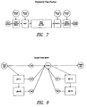
- Figure 7 illustrates graphic equalizer 100 composed of cascaded digital filters which operate on frequency bands indexed from 0 to N-1.
- the digital filter coefficients of the filters making up graphic equalizer 100 are adjusted as appropriate such that each filter present has the Q value which will linearize the responses of the filters at some defined distance (e.g., 1/3 octave) from that filter's center frequency.
- Figure 8 shows an alternate view of the first cascaded filter depicted in Figure 7.
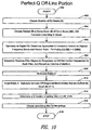
- Figure 9 shows a high-level logic flowchart depicting a real-time portion of one implementation of the herein described invention.
- Method step 700 illustrates the start of the process.
- Method step 702 shows reading from memory (e.g. , random access memory in a conventional microprocessor - not shown) user specified settings of a graphic equalizer (e.g., such as were shown and described in relation to 6A, above). Those having ordinary skill in the art will recognize that these are ordinarily set by the equipment user.
- memory e.g. , random access memory in a conventional microprocessor - not shown
- a graphic equalizer e.g., such as were shown and described in relation to 6A, above.
- Method step 704 depicts that in one implementation, the settings of the respective graphic equalizers are optionally convolved with a conventional smoothing filter.
- the foregoing is achieved by use of a simple moving average filter, while in other implementations, the foregoing is achieved by use of more sophisticated techniques (e.g., such as described in Addendum A) known to those of ordinary skill in the art.
- Specific implementation aspects of equations used in implementations of method step 704 are set forth under the "smoothing by moving average" section of Addendum A.
- Method step 706 illustrates multiplying the settings S, described in relation to method step 702, by a recalled correction matrix M to get a matrix of corrected settings U, and thereafter set the cut-boost levels of the individual filters to the corrected values contained in matrix U (e.g., as was shown and described above in relation to Figure 6A).
- the recalled correction matrix was previously created and stored by the offline portion of the process depicted and described in relation to Figure 10 below.
- Method step 708 shows that the adjusted cut-boost settings of the filter are then used to specify and recall the closest linearizing Q values of each individual filter which match that of the corrected settings (e.g., as was shown and described in relation to Figure 6B, above), and thereafter set the Q values of each filter to those closest linearizing Q values.
- the recalled linearizing Q values were previously created and stored by the offline portion of the process depicted and described in relation to Figure 10 below. It may seem more logical that Q values appropriate to the original user specified, as opposed to the corrected, cut-boost settings, be recalled and used. However, it has been unexpectedly found that the system actually provides advantages if the Q value appropriate to the corrected cut-boost settings is recalled and used. It is believed that this proves advantageous due to the filter interactions, but such understanding is not necessary to make and use the subject matter shown and described herein.
- Method step 710 depicts, that with the linearizing Q values and the corrected cut-boost settings so defined, in one implementation digital filter coefficients are calculated for the filters of the graphic equalizer such that the filters will have the desired Q values at the corrected cut-boost levels. Calculating such digital filter coefficients is well within the capabilities of one having ordinary skill in the art without undue experimentation. However, one specific example implementation which provides such digital filter coefficients is set forth in Addendum A under the "Filter Design Formulas" heading.
- Method step 712 illustrates the end of the real time portion.
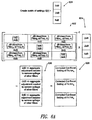
- Method step 600 depicts the start of the process.
- Method step 602 illustrates the operation of determining the number, N, of equalizer bands of a graphic equalizer.
- N would be 3 bands for graphic equalizer 100, but those skilled in the art will recognize that more typical values for N would be 7, 15, 30, or 60.
- Method step 604 shows that for each individual filter in the graphic equalizer, a set of linearizing Q values are calculated and stored such that the responses of each individual filter, at some distance (e.g., 1/3 octave) from the center frequency of the filter, va ry linearly when the cut-boost settings of the individual filters are varied linearly. Thereafter, such linearizing Q values are available for use by the real-time portion, such as was shown and described in relation to Figure 9.
- a set of linearizing Q values are calculated and stored such that the responses of each individual filter, at some distance (e.g., 1/3 octave) from the center frequency of the filter, va ry linearly when the cut-boost settings of the individual filters are varied linearly.
- Method step 606 which is optional and is not centrally related to the process illustrated in Figure 10, takes into account that magnitude responses of digital filters are often warped at high frequencies.
- Optional method step 606 may be used to partially compensate for this warping by the somewhat reducing the chosen Q values if the filter under consideration is one that deals with either substantially the lowest or substantially the highest frequencies processed by the graphic equalizer.
- step 608 depicts the creation of a spillage matrix having the presence filter magnitude response on all center frequencies for each filter. Restated, the matrix will have entries which represent the measured magnitude response at the output of a graphic equalizer which is due to the presence of energy which has "bled" beyond the defined passbands of individual filters in the graphic equalizer.
- the spillage matrix is created by (1) setting the cut-boost values of all filters in a graphic equalizer such that the outputs associated with such filters should be zero, (2) setting the cut-boost level of one of the filters such that an output associated with the filter (e.g., the output at the filter's center frequency) should be a non-zero value, (3) exciting the graphic equalizer with a white noise signal, and (4) obtaining the magnitude response output of the graphic equalizer at each center frequency of each filter in the graphic equalizer.
- Method step 610 illustrates the operation of normalizing the correction matrix of method step 608 (e.g., such as shown and described in relation to Figure 5B, above).
- Method step 612 shows the operation of creating a correction matrix by inverting the normalized spillage matrix of method step 610 (e.g., such as was shown and described in relation to Figure 5B, above). Shown is that, in one optional implementation, off-diagonal entries which are sufficiently small are truncated. What constitutes sufficiently small in any particular application is a design choice within the purview of the system designer dependent upon the tradeoff of accuracy versus speed of computation.
- Method step 614 shows calculating the Q values of the filters dependent upon the filter settings (e.g., such as shown and described in relation to Figure 5A1-3, above). Calculating such Q values, in light of the disclosure herein, is well within the capabilities of one having ordinary skill in the art and may be done without undue experimentation. However, one specific example implementation which provides such Q values is set forth in Addendum A under the "Determine a Q Function of Setting" heading.
- Method step 616 shows choosing a smoothing filter value associated with each of the recalled Q values of method step 614, and storing such smoothing filters in association with such Q values so that such Q values are available for use by the real-time portion of the process as shown and described above in relation to Figure 9.
- Method step 618 shows the end of the off-line portion of the process.
- smoothing There is an initial step in the real-time portion of that has been termed smoothing, and it allows the method to perform better in two ways. Without smoothing, the method chooses actual settings that result in a response that closely matches the original settings at those points. This normally works very well, but two undesirable effects are observed.
- the other undesirable effect is overshoot in the frequency response when there is a large step followed by a relatively flat area.
- the method will match the request, but is unable to control the response between filters, and the characteristics of the filters prevent a rectangular response step.
- the a1 and a2 formulas should be applied after scaling and rounding the other coefficients.
- one third octave constant (typical frequency spacing factor of EQ bands)
- the EQ is formed by cascading the filters for each band. At any given frequency, the resulting response is the sum of the individual responses in dB, because in the linear domain it is the product, and dB is a logarithmic scale.
- an implementer may opt for a hardware and/or firmware vehicle; alternatively, if flexibility is paramount, the implementer may opt for a solely software implementation; or, yet again alternatively, the implementer may opt for some combination of hardware, software, and/or firmware.
- any vehicle to be utilized is a choice dependent upon the context in which the vehicle will be deployed and the specific concerns (e.g., speed, flexibility, or predictability) of the implementer, any of which may vary.
- signal bearing media include, but are not limited to, the following: recordable type media such as floppy disks, hard disk drives, CD ROMs, digital tape, and computer memory; and transmission type media such as digital and analogue communication links using TDM or IP based communication links (e.g., packet links).
- electrical circuitry includes, but is not limited to, electrical circuitry having at least one discrete electrical circuit, electrical circuitry having at least one integrated circuit, electrical circuitry having at least one application specific integrated circuit, electrical circuitry forming a general purpose computing device configured by a computer program (e.g., a general purpose computer configured by a computer program which at least partially carries out processes and/or devices described herein, or a microprocessor configured by a computer program which at least partially carries out processes and/or devices described herein), electrical circuitry forming a memory device (e.g., forms of random access memory), and electrical circuitry forming a communications device (e.g., a modem, communications switch, or optical-electrical equipment).
- a computer program e.g., a general purpose computer configured by a computer program which at least partially carries out processes and/or devices described herein, or a microprocessor configured by a computer program which at least partially carries out processes and/or devices described herein
- electrical circuitry forming a memory device e
- any two components herein combined to achieve a particular functionality can be seen as “associated with” each other such that the desired functionality is achieved, irrespective of architectures or intermedial components.
- any two components so associated can also be viewed as being “operably connected”, or “operably coupled”, to each other to achieve the desired functionality.
Landscapes
- Tone Control, Compression And Expansion, Limiting Amplitude (AREA)
- Cigarettes, Filters, And Manufacturing Of Filters (AREA)
- Testing Of Coins (AREA)
- Cable Transmission Systems, Equalization Of Radio And Reduction Of Echo (AREA)
Applications Claiming Priority (2)
| Application Number | Priority Date | Filing Date | Title |
|---|---|---|---|
| US341812 | 2003-01-13 | ||
| US10/341,812 US7266205B2 (en) | 2003-01-13 | 2003-01-13 | Linearized filter band equipment and processes |
Publications (3)
| Publication Number | Publication Date |
|---|---|
| EP1437828A2 true EP1437828A2 (de) | 2004-07-14 |
| EP1437828A3 EP1437828A3 (de) | 2007-10-24 |
| EP1437828B1 EP1437828B1 (de) | 2010-07-14 |
Family
ID=32507504
Family Applications (1)
| Application Number | Title | Priority Date | Filing Date |
|---|---|---|---|
| EP04000530A Expired - Lifetime EP1437828B1 (de) | 2003-01-13 | 2004-01-13 | Vorrichtung und Prozesse zur Linearisierung von Interaktionen zwischen Filtern |
Country Status (4)
| Country | Link |
|---|---|
| US (1) | US7266205B2 (de) |
| EP (1) | EP1437828B1 (de) |
| AT (1) | ATE474375T1 (de) |
| DE (1) | DE602004028063D1 (de) |
Cited By (2)
| Publication number | Priority date | Publication date | Assignee | Title |
|---|---|---|---|---|
| WO2010138309A1 (en) * | 2009-05-26 | 2010-12-02 | Dolby Laboratories Licensing Corporation | Audio signal dynamic equalization processing control |
| US8929567B2 (en) | 2009-05-26 | 2015-01-06 | Dolby Laboratories Licensing Corporation | Equalization profiles for dynamic equalization of audio data |
Families Citing this family (39)
| Publication number | Priority date | Publication date | Assignee | Title |
|---|---|---|---|---|
| JP3920233B2 (ja) * | 2003-02-27 | 2007-05-30 | ティーオーエー株式会社 | ディップフィルタの周波数特性決定方法 |
| US7328412B1 (en) * | 2003-04-05 | 2008-02-05 | Apple Inc. | Method and apparatus for displaying a gain control interface with non-linear gain levels |
| US8284955B2 (en) | 2006-02-07 | 2012-10-09 | Bongiovi Acoustics Llc | System and method for digital signal processing |
| US10848118B2 (en) | 2004-08-10 | 2020-11-24 | Bongiovi Acoustics Llc | System and method for digital signal processing |
| US9281794B1 (en) | 2004-08-10 | 2016-03-08 | Bongiovi Acoustics Llc. | System and method for digital signal processing |
| US7254243B2 (en) * | 2004-08-10 | 2007-08-07 | Anthony Bongiovi | Processing of an audio signal for presentation in a high noise environment |
| US11431312B2 (en) | 2004-08-10 | 2022-08-30 | Bongiovi Acoustics Llc | System and method for digital signal processing |
| US8565449B2 (en) * | 2006-02-07 | 2013-10-22 | Bongiovi Acoustics Llc. | System and method for digital signal processing |
| US10158337B2 (en) | 2004-08-10 | 2018-12-18 | Bongiovi Acoustics Llc | System and method for digital signal processing |
| US8462963B2 (en) * | 2004-08-10 | 2013-06-11 | Bongiovi Acoustics, LLCC | System and method for processing audio signal |
| US9413321B2 (en) | 2004-08-10 | 2016-08-09 | Bongiovi Acoustics Llc | System and method for digital signal processing |
| US10701505B2 (en) | 2006-02-07 | 2020-06-30 | Bongiovi Acoustics Llc. | System, method, and apparatus for generating and digitally processing a head related audio transfer function |
| US10848867B2 (en) | 2006-02-07 | 2020-11-24 | Bongiovi Acoustics Llc | System and method for digital signal processing |
| US8705765B2 (en) * | 2006-02-07 | 2014-04-22 | Bongiovi Acoustics Llc. | Ringtone enhancement systems and methods |
| US9195433B2 (en) | 2006-02-07 | 2015-11-24 | Bongiovi Acoustics Llc | In-line signal processor |
| US9348904B2 (en) | 2006-02-07 | 2016-05-24 | Bongiovi Acoustics Llc. | System and method for digital signal processing |
| US10069471B2 (en) | 2006-02-07 | 2018-09-04 | Bongiovi Acoustics Llc | System and method for digital signal processing |
| US11202161B2 (en) | 2006-02-07 | 2021-12-14 | Bongiovi Acoustics Llc | System, method, and apparatus for generating and digitally processing a head related audio transfer function |
| US9615189B2 (en) | 2014-08-08 | 2017-04-04 | Bongiovi Acoustics Llc | Artificial ear apparatus and associated methods for generating a head related audio transfer function |
| US8150069B2 (en) * | 2006-03-31 | 2012-04-03 | Sony Corporation | Signal processing apparatus, signal processing method, and sound field correction system |
| US20070253577A1 (en) * | 2006-05-01 | 2007-11-01 | Himax Technologies Limited | Equalizer bank with interference reduction |
| US9423944B2 (en) * | 2011-09-06 | 2016-08-23 | Apple Inc. | Optimized volume adjustment |
| EP2590324B1 (de) | 2011-11-03 | 2014-01-08 | ST-Ericsson SA | Numerische Audiosignalentzerrung |
| US9344828B2 (en) | 2012-12-21 | 2016-05-17 | Bongiovi Acoustics Llc. | System and method for digital signal processing |
| US9883318B2 (en) | 2013-06-12 | 2018-01-30 | Bongiovi Acoustics Llc | System and method for stereo field enhancement in two-channel audio systems |
| US9264004B2 (en) | 2013-06-12 | 2016-02-16 | Bongiovi Acoustics Llc | System and method for narrow bandwidth digital signal processing |
| US9398394B2 (en) | 2013-06-12 | 2016-07-19 | Bongiovi Acoustics Llc | System and method for stereo field enhancement in two-channel audio systems |
| US9397629B2 (en) | 2013-10-22 | 2016-07-19 | Bongiovi Acoustics Llc | System and method for digital signal processing |
| US9906858B2 (en) | 2013-10-22 | 2018-02-27 | Bongiovi Acoustics Llc | System and method for digital signal processing |
| US9615813B2 (en) | 2014-04-16 | 2017-04-11 | Bongiovi Acoustics Llc. | Device for wide-band auscultation |
| US10820883B2 (en) | 2014-04-16 | 2020-11-03 | Bongiovi Acoustics Llc | Noise reduction assembly for auscultation of a body |
| US10639000B2 (en) | 2014-04-16 | 2020-05-05 | Bongiovi Acoustics Llc | Device for wide-band auscultation |
| US9564146B2 (en) | 2014-08-01 | 2017-02-07 | Bongiovi Acoustics Llc | System and method for digital signal processing in deep diving environment |
| US20170373656A1 (en) * | 2015-02-19 | 2017-12-28 | Dolby Laboratories Licensing Corporation | Loudspeaker-room equalization with perceptual correction of spectral dips |
| US9638672B2 (en) | 2015-03-06 | 2017-05-02 | Bongiovi Acoustics Llc | System and method for acquiring acoustic information from a resonating body |
| US9621994B1 (en) | 2015-11-16 | 2017-04-11 | Bongiovi Acoustics Llc | Surface acoustic transducer |
| WO2017087495A1 (en) | 2015-11-16 | 2017-05-26 | Bongiovi Acoustics Llc | Surface acoustic transducer |
| AU2019252524A1 (en) | 2018-04-11 | 2020-11-05 | Bongiovi Acoustics Llc | Audio enhanced hearing protection system |
| US10959035B2 (en) | 2018-08-02 | 2021-03-23 | Bongiovi Acoustics Llc | System, method, and apparatus for generating and digitally processing a head related audio transfer function |
Family Cites Families (4)
| Publication number | Priority date | Publication date | Assignee | Title |
|---|---|---|---|---|
| US4939782A (en) | 1987-06-24 | 1990-07-03 | Applied Research & Technology, Inc. | Self-compensating equalizer |
| US5737254A (en) * | 1995-10-27 | 1998-04-07 | Motorola Inc. | Symmetrical filtering apparatus and method therefor |
| US5687104A (en) | 1995-11-17 | 1997-11-11 | Motorola, Inc. | Method and apparatus for generating decoupled filter parameters and implementing a band decoupled filter |
| EP1263131A1 (de) * | 2001-05-28 | 2002-12-04 | Interuniversitair Micro-Elektronica Centrum | Filteranordnung und Verfahren zur Steuerung derselben |
-
2003
- 2003-01-13 US US10/341,812 patent/US7266205B2/en not_active Expired - Lifetime
-
2004
- 2004-01-13 AT AT04000530T patent/ATE474375T1/de not_active IP Right Cessation
- 2004-01-13 EP EP04000530A patent/EP1437828B1/de not_active Expired - Lifetime
- 2004-01-13 DE DE602004028063T patent/DE602004028063D1/de not_active Expired - Lifetime
Cited By (4)
| Publication number | Priority date | Publication date | Assignee | Title |
|---|---|---|---|---|
| WO2010138309A1 (en) * | 2009-05-26 | 2010-12-02 | Dolby Laboratories Licensing Corporation | Audio signal dynamic equalization processing control |
| US20120063614A1 (en) * | 2009-05-26 | 2012-03-15 | Crockett Brett G | Audio signal dynamic equalization processing control |
| US8929567B2 (en) | 2009-05-26 | 2015-01-06 | Dolby Laboratories Licensing Corporation | Equalization profiles for dynamic equalization of audio data |
| US8976979B2 (en) | 2009-05-26 | 2015-03-10 | Dolby Laboratories Licensing Corporation | Audio signal dynamic equalization processing control |
Also Published As
| Publication number | Publication date |
|---|---|
| US7266205B2 (en) | 2007-09-04 |
| DE602004028063D1 (de) | 2010-08-26 |
| EP1437828A3 (de) | 2007-10-24 |
| US20040136548A1 (en) | 2004-07-15 |
| EP1437828B1 (de) | 2010-07-14 |
| ATE474375T1 (de) | 2010-07-15 |
Similar Documents
| Publication | Publication Date | Title |
|---|---|---|
| EP1437828A2 (de) | Vorrichtung und Prozesse zur Linearisierung von Interaktionen zwischen Filtern | |
| US8422697B2 (en) | Background noise estimation | |
| CN102414746B (zh) | 在保持感知谱平衡的情况下的音频信号响度调整 | |
| JP4881918B2 (ja) | 適応性時間制御を用いるフィードバックリミッタ | |
| EP0843502B1 (de) | Schaltung zur Erkennung und Verhinderung von akustischen Rückkopplungen und Verwendung einer derartigen Schaltung in einem Lautsprechersystem | |
| DE112018001323B4 (de) | Aktive Geräuschminderungsvorrichtung und aktives Geräuschminderungsverfahren | |
| Välimäki et al. | Accurate cascade graphic equalizer | |
| US6442281B2 (en) | Loudness volume control system | |
| US4914564A (en) | Adaptive control system of high accuracy and low corrective energy consumption | |
| WO2010127024A1 (en) | Controlling the loudness of an audio signal in response to spectral localization | |
| US8583717B2 (en) | Signal processing circuit | |
| DE112016006169B4 (de) | Aktive Lärmschutzvorrichtung | |
| US6492865B1 (en) | Band pass filter from two filters | |
| US6404279B2 (en) | Band pass filter with improved group delay | |
| Freeborn et al. | Fractional-order lowpass elliptic responses of (1+ α)-order transfer functions | |
| CN114095836A (zh) | 音频处理装置及音频处理方法 | |
| JP2001257629A (ja) | ディジタル・グラファメトリック等化器 | |
| DE69615852T2 (de) | Dsp-dekodierer zur dekodierung von dolby-sr-kodierten audiosignalen | |
| JP3092968B2 (ja) | 電子的に制御可能な伝達特性を持つ回路装置 | |
| Afridi et al. | Adjustable spectral characteristics to design FIR filter using two-variable window function | |
| EP0991184A2 (de) | Digitale Klangregelung mit Koeffizienten in linearen Schritten | |
| CN116612738B (zh) | 一种基于自适应FxLMS算法的指定降噪量的方法 | |
| CN102868385B (zh) | 一种可配置系数的数字滤波器和实现方法 | |
| JP4214391B2 (ja) | デジタル・フィルタの設計方法 | |
| EP1263131A1 (de) | Filteranordnung und Verfahren zur Steuerung derselben |
Legal Events
| Date | Code | Title | Description |
|---|---|---|---|
| PUAI | Public reference made under article 153(3) epc to a published international application that has entered the european phase |
Free format text: ORIGINAL CODE: 0009012 |
|
| AK | Designated contracting states |
Kind code of ref document: A2 Designated state(s): AT BE BG CH CY CZ DE DK EE ES FI FR GB GR HU IE IT LI LU MC NL PT RO SE SI SK TR |
|
| AX | Request for extension of the european patent |
Extension state: AL LT LV MK |
|
| PUAL | Search report despatched |
Free format text: ORIGINAL CODE: 0009013 |
|
| AK | Designated contracting states |
Kind code of ref document: A3 Designated state(s): AT BE BG CH CY CZ DE DK EE ES FI FR GB GR HU IE IT LI LU MC NL PT RO SE SI SK TR |
|
| AX | Request for extension of the european patent |
Extension state: AL LT LV MK |
|
| 17P | Request for examination filed |
Effective date: 20071214 |
|
| 17Q | First examination report despatched |
Effective date: 20080529 |
|
| AKX | Designation fees paid |
Designated state(s): AT BE BG CH CY CZ DE DK EE ES FI FR GB GR HU IE IT LI LU MC NL PT RO SE SI SK TR |
|
| GRAP | Despatch of communication of intention to grant a patent |
Free format text: ORIGINAL CODE: EPIDOSNIGR1 |
|
| GRAS | Grant fee paid |
Free format text: ORIGINAL CODE: EPIDOSNIGR3 |
|
| GRAA | (expected) grant |
Free format text: ORIGINAL CODE: 0009210 |
|
| AK | Designated contracting states |
Kind code of ref document: B1 Designated state(s): AT BE BG CH CY CZ DE DK EE ES FI FR GB GR HU IE IT LI LU MC NL PT RO SE SI SK TR |
|
| REG | Reference to a national code |
Ref country code: GB Ref legal event code: FG4D |
|
| REG | Reference to a national code |
Ref country code: CH Ref legal event code: EP |
|
| REG | Reference to a national code |
Ref country code: IE Ref legal event code: FG4D |
|
| REF | Corresponds to: |
Ref document number: 602004028063 Country of ref document: DE Date of ref document: 20100826 Kind code of ref document: P |
|
| REG | Reference to a national code |
Ref country code: NL Ref legal event code: VDEP Effective date: 20100714 |
|
| PG25 | Lapsed in a contracting state [announced via postgrant information from national office to epo] |
Ref country code: FI Free format text: LAPSE BECAUSE OF FAILURE TO SUBMIT A TRANSLATION OF THE DESCRIPTION OR TO PAY THE FEE WITHIN THE PRESCRIBED TIME-LIMIT Effective date: 20100714 Ref country code: NL Free format text: LAPSE BECAUSE OF FAILURE TO SUBMIT A TRANSLATION OF THE DESCRIPTION OR TO PAY THE FEE WITHIN THE PRESCRIBED TIME-LIMIT Effective date: 20100714 Ref country code: AT Free format text: LAPSE BECAUSE OF FAILURE TO SUBMIT A TRANSLATION OF THE DESCRIPTION OR TO PAY THE FEE WITHIN THE PRESCRIBED TIME-LIMIT Effective date: 20100714 |
|
| PG25 | Lapsed in a contracting state [announced via postgrant information from national office to epo] |
Ref country code: SI Free format text: LAPSE BECAUSE OF FAILURE TO SUBMIT A TRANSLATION OF THE DESCRIPTION OR TO PAY THE FEE WITHIN THE PRESCRIBED TIME-LIMIT Effective date: 20100714 Ref country code: PT Free format text: LAPSE BECAUSE OF FAILURE TO SUBMIT A TRANSLATION OF THE DESCRIPTION OR TO PAY THE FEE WITHIN THE PRESCRIBED TIME-LIMIT Effective date: 20101115 Ref country code: CY Free format text: LAPSE BECAUSE OF FAILURE TO SUBMIT A TRANSLATION OF THE DESCRIPTION OR TO PAY THE FEE WITHIN THE PRESCRIBED TIME-LIMIT Effective date: 20100714 Ref country code: BG Free format text: LAPSE BECAUSE OF FAILURE TO SUBMIT A TRANSLATION OF THE DESCRIPTION OR TO PAY THE FEE WITHIN THE PRESCRIBED TIME-LIMIT Effective date: 20101014 |
|
| PG25 | Lapsed in a contracting state [announced via postgrant information from national office to epo] |
Ref country code: BE Free format text: LAPSE BECAUSE OF FAILURE TO SUBMIT A TRANSLATION OF THE DESCRIPTION OR TO PAY THE FEE WITHIN THE PRESCRIBED TIME-LIMIT Effective date: 20100714 Ref country code: SE Free format text: LAPSE BECAUSE OF FAILURE TO SUBMIT A TRANSLATION OF THE DESCRIPTION OR TO PAY THE FEE WITHIN THE PRESCRIBED TIME-LIMIT Effective date: 20100714 Ref country code: GR Free format text: LAPSE BECAUSE OF FAILURE TO SUBMIT A TRANSLATION OF THE DESCRIPTION OR TO PAY THE FEE WITHIN THE PRESCRIBED TIME-LIMIT Effective date: 20101015 |
|
| PG25 | Lapsed in a contracting state [announced via postgrant information from national office to epo] |
Ref country code: DK Free format text: LAPSE BECAUSE OF FAILURE TO SUBMIT A TRANSLATION OF THE DESCRIPTION OR TO PAY THE FEE WITHIN THE PRESCRIBED TIME-LIMIT Effective date: 20100714 |
|
| PLBE | No opposition filed within time limit |
Free format text: ORIGINAL CODE: 0009261 |
|
| STAA | Information on the status of an ep patent application or granted ep patent |
Free format text: STATUS: NO OPPOSITION FILED WITHIN TIME LIMIT |
|
| PG25 | Lapsed in a contracting state [announced via postgrant information from national office to epo] |
Ref country code: RO Free format text: LAPSE BECAUSE OF FAILURE TO SUBMIT A TRANSLATION OF THE DESCRIPTION OR TO PAY THE FEE WITHIN THE PRESCRIBED TIME-LIMIT Effective date: 20100714 Ref country code: IT Free format text: LAPSE BECAUSE OF FAILURE TO SUBMIT A TRANSLATION OF THE DESCRIPTION OR TO PAY THE FEE WITHIN THE PRESCRIBED TIME-LIMIT Effective date: 20100714 Ref country code: EE Free format text: LAPSE BECAUSE OF FAILURE TO SUBMIT A TRANSLATION OF THE DESCRIPTION OR TO PAY THE FEE WITHIN THE PRESCRIBED TIME-LIMIT Effective date: 20100714 Ref country code: SK Free format text: LAPSE BECAUSE OF FAILURE TO SUBMIT A TRANSLATION OF THE DESCRIPTION OR TO PAY THE FEE WITHIN THE PRESCRIBED TIME-LIMIT Effective date: 20100714 Ref country code: CZ Free format text: LAPSE BECAUSE OF FAILURE TO SUBMIT A TRANSLATION OF THE DESCRIPTION OR TO PAY THE FEE WITHIN THE PRESCRIBED TIME-LIMIT Effective date: 20100714 |
|
| 26N | No opposition filed |
Effective date: 20110415 |
|
| PG25 | Lapsed in a contracting state [announced via postgrant information from national office to epo] |
Ref country code: ES Free format text: LAPSE BECAUSE OF FAILURE TO SUBMIT A TRANSLATION OF THE DESCRIPTION OR TO PAY THE FEE WITHIN THE PRESCRIBED TIME-LIMIT Effective date: 20101025 |
|
| REG | Reference to a national code |
Ref country code: DE Ref legal event code: R097 Ref document number: 602004028063 Country of ref document: DE Effective date: 20110415 |
|
| PG25 | Lapsed in a contracting state [announced via postgrant information from national office to epo] |
Ref country code: MC Free format text: LAPSE BECAUSE OF NON-PAYMENT OF DUE FEES Effective date: 20110131 |
|
| REG | Reference to a national code |
Ref country code: CH Ref legal event code: PL |
|
| REG | Reference to a national code |
Ref country code: FR Ref legal event code: ST Effective date: 20110930 |
|
| REG | Reference to a national code |
Ref country code: IE Ref legal event code: MM4A |
|
| PG25 | Lapsed in a contracting state [announced via postgrant information from national office to epo] |
Ref country code: LI Free format text: LAPSE BECAUSE OF NON-PAYMENT OF DUE FEES Effective date: 20110131 Ref country code: FR Free format text: LAPSE BECAUSE OF NON-PAYMENT OF DUE FEES Effective date: 20110131 Ref country code: CH Free format text: LAPSE BECAUSE OF NON-PAYMENT OF DUE FEES Effective date: 20110131 |
|
| REG | Reference to a national code |
Ref country code: DE Ref legal event code: R119 Ref document number: 602004028063 Country of ref document: DE Effective date: 20110802 |
|
| PG25 | Lapsed in a contracting state [announced via postgrant information from national office to epo] |
Ref country code: IE Free format text: LAPSE BECAUSE OF NON-PAYMENT OF DUE FEES Effective date: 20110113 |
|
| PG25 | Lapsed in a contracting state [announced via postgrant information from national office to epo] |
Ref country code: LU Free format text: LAPSE BECAUSE OF NON-PAYMENT OF DUE FEES Effective date: 20110113 |
|
| PG25 | Lapsed in a contracting state [announced via postgrant information from national office to epo] |
Ref country code: DE Free format text: LAPSE BECAUSE OF NON-PAYMENT OF DUE FEES Effective date: 20110802 |
|
| PG25 | Lapsed in a contracting state [announced via postgrant information from national office to epo] |
Ref country code: TR Free format text: LAPSE BECAUSE OF FAILURE TO SUBMIT A TRANSLATION OF THE DESCRIPTION OR TO PAY THE FEE WITHIN THE PRESCRIBED TIME-LIMIT Effective date: 20100714 |
|
| PG25 | Lapsed in a contracting state [announced via postgrant information from national office to epo] |
Ref country code: HU Free format text: LAPSE BECAUSE OF FAILURE TO SUBMIT A TRANSLATION OF THE DESCRIPTION OR TO PAY THE FEE WITHIN THE PRESCRIBED TIME-LIMIT Effective date: 20100714 |
|
| PGFP | Annual fee paid to national office [announced via postgrant information from national office to epo] |
Ref country code: GB Payment date: 20160127 Year of fee payment: 13 |
|
| GBPC | Gb: european patent ceased through non-payment of renewal fee |
Effective date: 20170113 |
|
| PG25 | Lapsed in a contracting state [announced via postgrant information from national office to epo] |
Ref country code: GB Free format text: LAPSE BECAUSE OF NON-PAYMENT OF DUE FEES Effective date: 20170113 |