EP1436125B1 - Procede et dispositif de diminution d'erreurs lors du positionnement d'un bras robotique - Google Patents
Procede et dispositif de diminution d'erreurs lors du positionnement d'un bras robotique Download PDFInfo
- Publication number
- EP1436125B1 EP1436125B1 EP01274583A EP01274583A EP1436125B1 EP 1436125 B1 EP1436125 B1 EP 1436125B1 EP 01274583 A EP01274583 A EP 01274583A EP 01274583 A EP01274583 A EP 01274583A EP 1436125 B1 EP1436125 B1 EP 1436125B1
- Authority
- EP
- European Patent Office
- Prior art keywords
- coordinate system
- robot
- location
- matrix
- angles
- Prior art date
- Legal status (The legal status is an assumption and is not a legal conclusion. Google has not performed a legal analysis and makes no representation as to the accuracy of the status listed.)
- Expired - Lifetime
Links
Images


Classifications
-
- G—PHYSICS
- G05—CONTROLLING; REGULATING
- G05B—CONTROL OR REGULATING SYSTEMS IN GENERAL; FUNCTIONAL ELEMENTS OF SUCH SYSTEMS; MONITORING OR TESTING ARRANGEMENTS FOR SUCH SYSTEMS OR ELEMENTS
- G05B19/00—Programme-control systems
- G05B19/02—Programme-control systems electric
- G05B19/18—Numerical control [NC], i.e. automatically operating machines, in particular machine tools, e.g. in a manufacturing environment, so as to execute positioning, movement or co-ordinated operations by means of programme data in numerical form
- G05B19/401—Numerical control [NC], i.e. automatically operating machines, in particular machine tools, e.g. in a manufacturing environment, so as to execute positioning, movement or co-ordinated operations by means of programme data in numerical form characterised by control arrangements for measuring, e.g. calibration and initialisation, measuring workpiece for machining purposes
- G05B19/4015—Numerical control [NC], i.e. automatically operating machines, in particular machine tools, e.g. in a manufacturing environment, so as to execute positioning, movement or co-ordinated operations by means of programme data in numerical form characterised by control arrangements for measuring, e.g. calibration and initialisation, measuring workpiece for machining purposes going to a reference at the beginning of machine cycle, e.g. for calibration
-
- B—PERFORMING OPERATIONS; TRANSPORTING
- B25—HAND TOOLS; PORTABLE POWER-DRIVEN TOOLS; MANIPULATORS
- B25J—MANIPULATORS; CHAMBERS PROVIDED WITH MANIPULATION DEVICES
- B25J9/00—Programme-controlled manipulators
- B25J9/16—Programme controls
- B25J9/1679—Programme controls characterised by the tasks executed
- B25J9/1692—Calibration of manipulator
-
- G—PHYSICS
- G05—CONTROLLING; REGULATING
- G05B—CONTROL OR REGULATING SYSTEMS IN GENERAL; FUNCTIONAL ELEMENTS OF SUCH SYSTEMS; MONITORING OR TESTING ARRANGEMENTS FOR SUCH SYSTEMS OR ELEMENTS
- G05B2219/00—Program-control systems
- G05B2219/30—Nc systems
- G05B2219/39—Robotics, robotics to robotics hand
- G05B2219/39022—Transform between measuring and manipulator coordinate system
-
- G—PHYSICS
- G05—CONTROLLING; REGULATING
- G05B—CONTROL OR REGULATING SYSTEMS IN GENERAL; FUNCTIONAL ELEMENTS OF SUCH SYSTEMS; MONITORING OR TESTING ARRANGEMENTS FOR SUCH SYSTEMS OR ELEMENTS
- G05B2219/00—Program-control systems
- G05B2219/30—Nc systems
- G05B2219/39—Robotics, robotics to robotics hand
- G05B2219/39182—Compensation for base, floor deformation
-
- G—PHYSICS
- G05—CONTROLLING; REGULATING
- G05B—CONTROL OR REGULATING SYSTEMS IN GENERAL; FUNCTIONAL ELEMENTS OF SUCH SYSTEMS; MONITORING OR TESTING ARRANGEMENTS FOR SUCH SYSTEMS OR ELEMENTS
- G05B2219/00—Program-control systems
- G05B2219/30—Nc systems
- G05B2219/39—Robotics, robotics to robotics hand
- G05B2219/39189—Compensate for dead weight of tool as function of inclination tool
-
- G—PHYSICS
- G05—CONTROLLING; REGULATING
- G05B—CONTROL OR REGULATING SYSTEMS IN GENERAL; FUNCTIONAL ELEMENTS OF SUCH SYSTEMS; MONITORING OR TESTING ARRANGEMENTS FOR SUCH SYSTEMS OR ELEMENTS
- G05B2219/00—Program-control systems
- G05B2219/30—Nc systems
- G05B2219/40—Robotics, robotics mapping to robotics vision
- G05B2219/40248—Manipulator on slide
-
- G—PHYSICS
- G05—CONTROLLING; REGULATING
- G05B—CONTROL OR REGULATING SYSTEMS IN GENERAL; FUNCTIONAL ELEMENTS OF SUCH SYSTEMS; MONITORING OR TESTING ARRANGEMENTS FOR SUCH SYSTEMS OR ELEMENTS
- G05B2219/00—Program-control systems
- G05B2219/30—Nc systems
- G05B2219/40—Robotics, robotics mapping to robotics vision
- G05B2219/40623—Track position of end effector by laser beam
-
- G—PHYSICS
- G05—CONTROLLING; REGULATING
- G05B—CONTROL OR REGULATING SYSTEMS IN GENERAL; FUNCTIONAL ELEMENTS OF SUCH SYSTEMS; MONITORING OR TESTING ARRANGEMENTS FOR SUCH SYSTEMS OR ELEMENTS
- G05B2219/00—Program-control systems
- G05B2219/30—Nc systems
- G05B2219/49—Nc machine tool, till multiple
- G05B2219/49195—Slide, guideway, robot arm deviation
Definitions
- the invention relates to methods and devices for reducing errors in the positioning of a robot arm, in particular for compensating for deformation-related deviations.
- the movement axes of a robot are measured horizontally to the horizon with a theodolite and then aligned.
- the influence of the deformation of the linear axis as well as the deflection of the robot arm on the position of the robot in the Cartesian space during the procedure on the axis is not considered in the conventional method.
- the robot has both positional and orientation errors in performing its tasks.
- the desired position of the tool in the working area of the robot can be specified in a reference coordinate system and for a respective predetermined desired position of the tool corresponding angular positions of the robot joints calculated by a robot controller and be set.
- the respective actual position of the tool with respect to predetermined measuring points which are predeterminable by the robot controller as desired positions, measured within the working range of the robot and the respective deviation between the actual and desired position as an element of a position error space matrix in a Storage medium deposited, where only as many measuring points are set as are necessary to form the position error space matrix taking advantage of the symmetry properties of a respective reference coordinate system.
- the deviations between the actual position and the desired position at the predetermined measuring points are used to interpolate the deviations of all tool positions lying between the measuring points. From the deviations correction values for the angular positions of the robot joints are calculated and used for position correction of the tool.
- WO 0100370 is a method and apparatus for calibrating manipulators and entrained optical measuring devices, in particular of multi-axis measuring robots with 3D sensors, within a measuring station for workpieces, in particular for vehicle bodyworks, known, in which method the calibration takes place in a measuring cascade with at least three calibration steps , wherein successively the optical measuring device with its operating point, the manipulator with its axes and then the assignment of the manipulator are calibrated to the workpiece.
- the optical measuring device is calibrated with its operating point on the manipulator by means of a precisely positionable test device with a reference pattern which is temporarily positioned in the region of the operating point and brought to coincide with the operating point by a relative movement relative to the optical measuring device, after which the reference pattern for determining the location Coordinates of the working point is measured.
- the test device is brought into position with the fixed in the desired position of the operating point reference pattern and checks the compliance of target and actual position, wherein the correction of possible deviations readjusted the optical measuring device or readjusted the reference pattern and to determine the location coordinates of the operating point is measured again.
- the manipulator is calibrated with its axes on a calibration body with at least one measuring mark with a flat rotationally symmetrical contour, wherein the measuring mark is approached with the optical measuring device from different directions and with different axis orientations of the manipulator.
- the US 4,590,578 describes a method for accurately performing the operation of a robot at a plurality of locations of a workpiece.
- the workpiece is mounted on a fixture.
- the robot is positioned so that the positions of alignment points on the carrier are measured.
- a first coordinate transformation is determined.
- corrected coordinates of these features are calculated from nominal coordinates of at least two features of the workpiece.
- a second coordinate transformation is set. With the help of these, the target coordinates of the robot are corrected.
- the EP 0 470 257 A1 discloses a robotic calibration system for converting an off-line rogram into a motion program for a robot using a transformation matrix. At least four out-of-plane points on a workpiece are probed to determine the transformation matrix.
- the invention is based on the object of providing methods and a device with which such position and orientation errors are compensated or at least substantially reduced.
- the orientation deviation can be caused, in particular, by an external disturbing force, e.g. gravity, acts.
- the robot may be arranged on a rail which is twisted under the weight of the robot, whereby the robot changes its spatial orientation.
- the rail may bend down under the weight of the robot, causing a lateral downward shift of the robot.
- the workpiece coordinate system can be selected as the reference coordinate system, that is, at the same time be the workpiece and reference coordinate system.
- the workpiece coordinate system is used as a reference coordinate system, so that the workpiece coordinate system and the reference coordinate system are identical and the calibration of the robot coordinate system takes place directly opposite to the workpiece coordinate system.
- the robot can be moved to a plurality of locations and the method can be carried out independently of each other for at least a part of these locations. According to one embodiment of the invention, therefore, the robot coordinate system for at least a portion of these locations in each case with respect to the reference coordinate system einmessbar.
- first the first location coordinate system is measured against the workpiece coordinate system and then the second against the first location coordinate system, so that the second location coordinate system indirectly, namely on the detour via the first location coordinate system, against the workpiece coordinate system is measured.
- deviations or additional deviations determined according to method steps b) are used in accordance with the invention to calculate the coordinates based on the robot coordinate system for each target point of the workpiece to be controlled by the robot arm taking into account the deviation ("mathematical correction") or, alternatively, the underlay to influence the robot so that the mentioned deviations are reduced, preferably minimized ("mechanical correction").
- the support of the robot at the second location can be influenced ("mechanical correction") such that the additional orientation deviation and thus at least part of the elements of the 3 * 3 additional matrix are reduced, preferably minimized, so that the orientation of the second location Coordinate system is approximated to that of the first location coordinate system.
- This procedure can be repeated until the deviations of the elements of the 3 * 3 additional matrix from the corresponding elements of the 3 * 3 matrix are each less than the respective predetermined limit values, i. the orientation of the second location coordinate system of that of the first location coordinate system are gradually adjusted.
- the robot can be moved to a plurality of locations and this method can be performed in an analogous manner for at least a part of these locations, whereby an advantageous standardization of the orientation belonging to these locations, each related to the robot coordinate systems is achieved.
- a simplified conversion of the coordinates of an arbitrary Aufuss from the workpiece coordinate system in the robot coordinate system is possible for this part of the sites, as this only the location of the locations and the orientation only the first location coordinate system is needed.
- the robot may be movable between a plurality of locations and the method may be performed sequentially for the locations, with each location having its own set of three angles of rotation or its own 3 * 3 matrix or set of three angles of rotation and a separate set of three offset distances or a separate 4 * 4 matrix is determined. This procedure is particularly advantageous if the orientation of the robot coordinate system varies depending on the location.
- results obtained in this way can be used to determine from the position of at least two of the locations and the rotation angles or offset distances belonging to these at least two locations, continuous functions which describe the location dependence of the angles of rotation or offset distances, and these functions can do so be used to calculate any set of angles of rotation or a set of offset distances for any further locations located between the locations.
- the orientation or position and orientation of the associated robot coordinate system can be determined for such locations, for which no separate measurement was made.
- the method may be performed sequentially for a plurality of different loading conditions of the robot, with each of these loading conditions having its own set of three angles of rotation or a separate 3 * 3 matrix or set of three angles of rotation, as well as a separate set of three offset distances a separate 4 * 4 matrix is determined.
- This procedure is advantageous when the orientation of the robot coordinate system varies depending on the loading condition of the robot.
- continuous functions can be determined which describe the dependence of the rotational angles or offset distances on the load of the robot, and these functions can be used be used to calculate a set of angles of rotation or a set of offset distances for any loading condition. In this way, the orientation or position and orientation of the associated robot coordinate system can be determined for such load conditions, for which no separate measurement was made.
- the method according to the invention can be carried out in succession for a plurality of different deflections of the robot arm, for each of these deflections a separate set of three angles of rotation or a separate 3 * 3 matrix or a separate set of three angles of rotation and a separate set of three offset distances or a separate 4 * 4 matrix is determined.
- This procedure is particularly advantageous if the orientation of the robot coordinate system varies depending on the deflection of the robot arm.
- each belonging rotation angles or offset distances continuous functions can be determined, which describe the dependence of the rotation angle or offset distances of the deflection, and these functions can be used to, for any deflection, a set of angles of rotation or calculate a set of offset distances.
- the orientation or position and orientation of the associated robot coordinate system can be determined for such deflections, for which no separate measurement was made. All these functions can e.g. Regression or fit functions that allow not only an interpolation between two locations or load states or deflections, but also an extrapolation.
- the Auf can be re-selected each time the procedure.
- they may each be chosen such that their coordinates with respect to the robot coordinate system for each of the locations or each of the load conditions are respectively constant, which means that selected for the inventive measurement at least three points in Depending on the location and / or the load state in their entirety with the robot coordinate system mitwandern, but always remain in constant, rigid formation with each other.
- the detection of the location dependence of the orientation of the robot coordinate system is not falsified by an overlapping influence of the deflection of the robot arm that changes from location to location.
- the repeat accuracy of the robot for determining its orientation is advantageously utilized in this way.
- the robot can be moved linearly or two-dimensionally or three-dimensionally to the locations.
- the workpiece coordinate system, the reference coordinate system and the robot coordinate system are each Cartesian coordinate systems.
- the measuring device is in this case a coordinate measuring device for Cartesian coordinates.
- the inventive method can be used very advantageous not only for so-called load compensation.
- the methods are also suitable for ensuring a reduction or compensation of the positioning errors even if the base itself, eg rail, on which the robot is moving, is non-uniform with respect to its inclination against the horizontal, eg has oblique points, or deformed from place to place under the weight load by the robot to different degrees.
- the base itself eg rail
- this may be due to the fact that the rail is supported only at certain spaced locations relative to the ground, so that the deformation of the rail under the weight of the robot depends on the distance to these locations, or in that the rail For example, due to damage in places bent or warped.
- Another cause of such spatial inhomogeneities may be thermal effects, material wear or material fatigue.
- the deflection of the floor from one location to another under the weight of the robot or other furnishings may also result in a location dependent inclination of the robot to lead.
- Another cause of such spatial inhomogeneities may be different material properties of the pad from place to place.
- the invention is also suitable for effectively counteracting positioning errors which are based on such an inhomogeneous inclination of the substrate present in the working area of the robot.
- the invention may be used to reduce or eliminate the effect of variations in the timing of nonuniformities of the kind referred to.
- the method or methods must be repeated only at appropriate intervals.
- Such temporal changes can e.g. caused by wear of material or by the slow "settling" of the foundations, which sometimes occurs in large buildings, or slight shifts due to light earthquakes.
- the robot may be mounted on a pad, such as a pad.
- a rail one-dimensionally movable and the inventive method along the rail can be carried out sequentially at a plurality of spaced-apart locations.
- the robot can be moved in a two-dimensional manner on a base, wherein the method according to the invention is carried out along the rail successively at a plurality of spaced-apart locations which form a regular or irregular two-dimensional grid.
- the Fig.1 to 7 serve to exemplify further variants of the inventive method for reducing errors in the positioning of a robot arm relative to a workpiece FIGS. 1 to 3 from the special case, which is particularly advantageous for many applications, it is assumed that the workpiece coordinate system has been selected as the reference coordinate system, so that the workpiece coordinate system and the reference coordinate system are identical.
- the mentioned positioning errors are described in reference to FIGS Fig. 1 to 7 explained example due to the fact that the robot coordinate system KSR with respect to the workpiece coordinate system KSW has an orientation deviation OA, which may be due to the weight of the robot R and thereby caused bending deformation, for example.
- Fig. 1 schematically shows by a first example, a workpiece W, which here is the body shell of a car and on which a workpiece coordinate system KSW is related, and one on a rail 5 one-dimensional, rotatable about its vertical axis robot R 'with an arm A' , which can raise and lower, so that the robot R 'by means of the arm A' a number of points of the workpiece W is capable of controlling.
- the robot R ' is related to a robot coordinate system KSR.
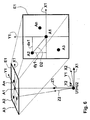
- Fig. 2 shows a schematic representation of another robot R with an arm A, which is located on a pedestal 6 and successively five different Auftim Q1, Q2, Q3, Q4, Q5 drives, with the corresponding, successively occupying positions of the arm A in Fig. 2 for reasons of clarity are shown at the same time and the workpiece W is not shown.
- the robot R can be moved to different locations, which in Fig. 2 but not shown.
- the workpiece W the workpiece coordinate system with the axes KSW xw, yw, z w assigned ( Fig. 3 ).
- the robot is assigned its own coordinate system with the axes x R , y R , z R , namely the robot coordinate system KSR.
- a measuring device With a measuring device, at least three of the robot R (in order to carry out the method according to the invention) are used.
- Fig. 2 to be approached points, first points of reference P1, P2, called P3, measured in the workpiece coordinate system KSW and so determines the position of the robot coordinate system KSR relative to this workpiece coordinate system KSW computationally.
- the mutual orientation of the two coordinate systems KSW, KSR is given by three angles of rotation ⁇ , ⁇ , ⁇ and the mutual lateral position of the two coordinate systems by three offset distances dx, dy, dz.
- FIG. 3 serves to illustrate the determination of the mutual orientation of the two coordinate systems KSW, KSW.
- the robot arm A ( Fig. 2 )
- a point P 1 ie the position of the robot arm A is given or defined by the point P 1 , whose position in the robot coordinate system KSR with the axes x R , y R , z R is given by a vector V R1 with the components R X1 , R Y1 , R Z1 , ie the point P 1 is in the robot coordinate system KSR characterized by the coordinates R X1 , R Y1 , R Z1 .
- a second point P 2 in the robot coordinate system KSR is characterized by the coordinates R X2 , R Y2 , R Z2 and in the workpiece coordinate system KSW by the coordinates W X2 , W Y2 , W Z2 .
- a third point P 3 in the robot coordinate system KSR is characterized by the coordinates R X3 , R Y3 , R Z3 and in the workpiece coordinate system KSW by the coordinates W X3 , W Y3 , W Z3 .
- This matrix thus describes a transfer or transformation of a coordinate system into another, ie a rotation of a coordinate system in space, which is defined by a rotation angle ⁇ about the x-axis, by a rotation angle ⁇ about the y-axis and by a rotation angle ⁇ around the z-axis.
- a rotation angle ⁇ about the x-axis
- a rotation angle ⁇ about the y-axis
- a rotation angle ⁇ around the z-axis a rotation angle ⁇ around the z-axis.
- the robot arm A is required to perform an operation, e.g. to make a weld at a given point of a raw body in the context of motor vehicle production, to be brought into a position which corresponds to a certain further reference point P4, namely the target point of the robot arm A on the raw body.
- the position of the raw body and thus the coordinates of the target point P4 in the workpiece coordinate system are known.
- the robot arm A is now to be controlled so that its position corresponds to the target point P4, i. so that the welding takes place at the target point P4.
- the matrix M33 or M44 is known, which means that the coordinates of the Aufuss P4 in the robot coordinate system KSR by means of the matrix M33 or the matrix M44 are determinable and the robot arm A can therefore be controlled accordingly ("mathematical correction", ie reduction of positioning errors by recalculation of the coordinates using the above-explained calibration).
- the coordinates related to the robot coordinate system KSR for each target point P4 of the workpiece W to be controlled by the robot arm A are determined according to the invention by means of the coordinates of the target point P4 related to the reference coordinate system KSref and by means of the 3 * 3 matrix M33 or by means of the 4 * 4-matrix M44 calculated by a calculator; in the case of the calculation using the 3 ⁇ 3 matrix M33, of course, the relative position of the origins of the two coordinate systems KSW, KSR must be known and included.
- Another or further cause for a change in the orientation of the robot coordinate system KSR can be given by the fact that the robot must move between different locations in the context of its work in relation to the workpiece coordinate system KSR, eg on a rail 5 back and drives away ( Fig. 1 ), wherein, for example, the inclination of the ground or, for example, the deformation of the rail 5 or the ground under the weight of the robot R is different from location to location.
- gravity acts as an interfering force, although the extent of the disturbance caused by it, namely change in the orientation of the robot coordinate system, is dependent on location. If, for example, the rail 5 bends downwards at a location under the weight of the robot R, a positional shift of the robot coordinate system KSR also occurs.
- such additional positioning errors are eliminated or substantially reduced by performing a separate measurement in the manner explained above for a plurality of locations and / or loading conditions of the robot R, which means that for a plurality of individual Locations and / or a plurality of individual loading conditions of the robot R each own 3 * 3 matrix M'33 or respectively a separate 4 * 4 matrix M'44 determined and used to control the robot arm.
- a separate measurement in the manner explained above for a plurality of locations and / or loading conditions of the robot R, which means that for a plurality of individual Locations and / or a plurality of individual loading conditions of the robot R each own 3 * 3 matrix M'33 or respectively a separate 4 * 4 matrix M'44 determined and used to control the robot arm.
- at least one new matrix M'33 or M'44 is determined, in which the additional disturbing influence is already considered from the outset ("mathematical correction").
- the robot R receives the command R in its robot coordinate system KSR with its arm A the coordinates R X4 , R Y4 , R Z4 , which were determined by means of the matrix M44 or M33 by coordinate transformation from the coordinates W X4 , W Y4 , W Z4 .
- the robot will be assigned a new job in which he has to carry a mass of X kg.
- This results in an additional bending deformation of the robot R and thus to a rotation of the robot coordinate system KSR against the workpiece coordinate system KSW, resulting in additional positioning errors of the kind explained above.
- these can be compensated or substantially reduced by first of all re-measuring the two coordinate systems KSR, KSW against one another, namely while the robot R carries the mass of X kg.
- the new matrix M'44 or M'33 is found, which is different from the previously determined original matrix M44 or M33.
- the target point P4 is to be controlled again by the robot arm A during the new operation, which in the workpiece coordinate system KSW still has the coordinates W X4 , W Y4 , W Z4 , but now the coordinates R ' X4 in the robot coordinate system.
- R ' Y4 , R' has Z4 .
- the robot is now commanded to control in the robot coordinate system with his arm the new coordinates R ' X4 , R' Y4 , R ' Z4 , which by means of the matrix M'44 or M'33 by coordinate transformation from the coordinates W X4 , W Y4 , W Z4 were determined and according to the invention are corrected in relation to the previous to be controlled by the robot coordinates R X4 , R Y4 , R Z4 corresponding to the bending deformation.
- the coordinates of the points to be controlled determine again by means of the original matrix M44 or M33.
- a robot R ' is considered, which can linearly reciprocate on a rail 5 between different locations ( Fig. 1 ).
- a traversing axis may consist of two rails 5 on which the robot travels. These rails 5 should ideally be parallel and non-deformable.
- the transformation matrices of the measured robot positions would have no twists with respect to a selected reference coordinate system. In practice this is not the case.
- RoboTwist During the movement of a robot on the travel axis, it "dances" on the two rails 5 and thus executes a fluctuating movement, the so-called RoboTwist.
- the rail 5 will also deform elastically under the weight of the robot R ', the amount of deformation usually not being constant over the length of the rail 5, but due to inhomogeneities of the material, of the underground etc. varies from place to place.
- the angular orientation of the robot coordinate system KSR is therefore location-dependent, which means that 5 additional positioning errors of the type described above arise by relocation of the robot R 'even if the location of each location known and taken into account in the control of Ziei.s is.
- a plurality n of locations are defined along the rail, which are referred to below as S1, S2,... Sn ( Fig. 4 ).
- the mutual distance of the locations can be chosen evenly, but this is not necessary; Rather, even irregular distances are possible.
- the robot on the rail 5 is moved to the location S1, which may coincide with the starting point of the rail 5, for example. Due to the mentioned additional interference, the robot coordinate system KSR at the location S1 passes into a first location coordinate system KSS1, which is measured against the workpiece coordinate system KSW with the aid of at least three first reference points P1, P2, P3 as explained above. A first 3 * 3 or 4 * 4 matrix M1 is obtained which belongs to location S1.
- the robot is moved to a second location S2 spaced apart from the first location S1 by a distance dS, where the robot coordinate system KSR eg changes due to changed ground conditions into a second location coordinate system KSS2, which in turn is measured against the workpiece coordinate system KSW explained above, but in place of the previous at least three first Aufnum P1, P2, P3 at least three second Aufnum Q1, Q2, Q3 can occur, for example, if the previous Maunum P1, P2, P3 for the robot arm from the point of view S2 not reachable are.
- the look-up points can be used with each new implementation of the method, i. for each location S1 ... Sn, be re-elected.
- the second points of view Q1, Q2, Q3 are chosen such that their coordinates in the second location coordinate system KSS2 correspond exactly to the coordinates of the first points P1, P2, P3 in the first location coordinate system KSS1, which means that the coordinates of the points of view with respect to the robot coordinate system KSR are constant for each of the locations.
- a new 3 ⁇ 3 or 4 ⁇ 4 matrix M2 is obtained for the location S2, which serves especially to determine the coordinates of the target points to be controlled by the robot arm in the robot coordinate system if the robot is located on the one belonging to this matrix M2 Location S2 is located.
- the robot is driven successively to all other locations Sn and there, respectively, the robot coordinate system KSR, which at each location S1 ... Sn in a location associated with this coordinate system KSS1 ... KSSn, against the workpiece coordinate system KSW measured, each proceeding analogously to the above-explained procedure.
- the robot coordinate system KSR which at each location S1 ... Sn in a location associated with this coordinate system KSS1 ... KSSn, against the workpiece coordinate system KSW measured, each proceeding analogously to the above-explained procedure.
- a 3 * 3 or 4 * 4 matrix M1... Mn is generated, which transforms the respective location coordinate system KSS1... KSSn onto the workpiece coordinate system KSW or vice versa.
- the origins of the location coordinate systems are in Fig. 4 characterized by the points U1 ... Un.
- An alternative possibility according to the invention is to compare the matrices M1... Mn belonging to the individual locations (or the respectively associated sets of angles of rotation ⁇ 1, ⁇ 1, .gamma.1..., .Beta.n, .gamma.n) with one another and one of these matrices Mi or to define one of these sets of rotation angles ⁇ i, ⁇ i, ⁇ i, which belong to a selected location Si, as the reference or reference rotation angle set for the other sets of rotation angles.
- the location coordinate system KSSi belonging to the selected location Si serves as a reference or reference coordinate system KSref and, of course, can be measured in accordance with the above-explained method with respect to the workpiece coordinate system KSW; Alternatively, the zero-coordinate system can be measured or measured in a conventional manner against the workpiece coordinate system KSW.
- the selected location Si can be, for example, the location S1 ( Fig. 4 ), so that the zero or reference coordinate system is given by the first location coordinate system KSS1, and is preferably selected in the beginning or end region of the rail 5.
- the remaining location coordinate systems instead of being measured directly against the workpiece coordinate system KSW, can now be measured against the zero coordinate system KSSi.
- the Aufally used for this measurement can also be re-selected each measurement of a location coordinate system against the zero coordinate system.
- the landmarks can each be chosen so that their coordinates are constant with respect to the robot coordinate system for each of the sites, which means that the selected landmarks migrate in their entirety with the robot coordinate system, but always with each other in a constant remain rigid formation. In this way, the repeatability of the robot is advantageously utilized to determine its orientation.
- Rail 5 ( Fig. 4 ) can be influenced in a targeted manner, eg by backing support bodies or in some other way, by deliberately reducing the deviations or the additional deviations ("mechanical correction"). This is possible since these deviations or additional deviations are known according to the above method and provide a measure of the mismatch of the rail 5 at the respective locations.
- the robot coordinate system KSR is re-measured at the relevant location and in a still existing
- the rail 5 can be adjusted step by step at all locations one after the other, ie the matrices M1... Mn belonging to the location ducks are continuously adjusted to each other until the mismatches, ie the additional deviations at all other locations in each case fall below a predetermined minimum value.
- homogenization of the deformation behavior of the rail 5 is achieved very advantageously by targeted local interventions.
- the reference coordinate system KSref may be any coordinate system whose position and orientation relative to the workpiece coordinate system KSW are known, e.g. by being measured according to the invention or in a conventional manner.
- the reference coordinate system KSref and the workpiece coordinate system KSW may coincide, in which case the additional orientation deviations of the location coordinate systems from the reference coordinate system KSref are identical to the deviations of the location coordinate systems from the workpiece coordinate system KSW.
- a homogenization of the deformation behavior of the rail 5 then usually does not lead to all these deviations going to zero, but rather to the fact that all these deviations are approximated to a certain reference deviation. Therefore, it may be very advantageous to choose as zero or reference coordinate system, which belongs to one of the locations S1 ...
- the said homogenization of the deformation behavior of the rail 5 always means that by this variant of the method according to the invention not only a convergence of all additional deviations against a certain uniform final value, but a convergence thereof to zero is achieved, which is advantageous in many cases, Since deviations from zero are often easier and more precisely detected by measurement than deviations from a finite value.
- the locations can be chosen arbitrarily tight.
- the orientation of the robot coordinate system KSR finally remains virtually completely constant in a method of the robot over the entire rail length.
- a target point P6 may e.g. be attainable for the robot R both when the robot R is at a specific location Sj, and when it is at a neighboring location Sj + 1.
- One and the same destination point P6 can then be controlled in one case by means of a matrix Mj belonging to the location Sj, in the other case by means of another matrix Mj + 1 belonging to the adjacent measuring point Sj + 1.
- the applicability of the invention is not limited to stationary or only linearly movable robot.
- the locations are not on a straight line, but form a regular or irregular 2-dimensional grid covering the area, for each grid point its own associated matrix is measured.
- the spatial dependence of the orientation of the robot coordinate system is thus taken into account and compensated for in two dimensions at the same time.
- the locations can form a regular or irregular 3-dimensional detent covering the range of motion of the robot, in turn, for each grid point its own associated Matrix is measured.
- the spaces between the locations are detected by interpolation.
- the rotation angle ⁇ , ⁇ , ⁇ which describe the mutual spatial orientation of the robot and the workpiece coordinate system, for a located between two locations Sk, Sk + 1 intermediate location of a linear interpolation between the rotation angles ⁇ k and ⁇ k +1, ⁇ k and ⁇ k + 1 as well as ⁇ k and ⁇ k + 1, which were determined for these two sites.
- the interpolation for each of the angles of rotation ⁇ , ⁇ , ⁇ can each take place with the aid of a fit surface, in the case of a three-dimensional movability of the robot, in each case with the aid of a fit hypersurface. In this way, a stepless location-dependent correction is possible according to the invention.
- the correction of the bending deformation already explained above which is caused by different deflections of the robot arm from the central axis or the vertical projection of the foot point of the robot, can be extended by interpolation to intermediate values of the deflection, for which no own measurement was made.
- a linear interpolation or the creation of a fit function for the individual rotation angle ⁇ , ⁇ , ⁇ of the mutual orientation of the coordinate systems in dependence on the deflection is possible.
- 3 * 3 matrices describe only the mutual angular orientation ⁇ , ⁇ , ⁇ of the two coordinate systems, not the mutual lateral position of the two coordinate zero points in space.
- the latter is often also known without mutual measurement of the coordinate systems in the manner explained above, in particular when the robot is stationary or, e.g. can be moved by defined distances by means of a stepper motor so that the position of the robot and thus also that of the robot coordinate zero point moved with it follow from the number of revolutions of the stepper motor, or e.g. is measured by means of its own transducer:
- a 4 * 4 matrix for coordinate transformation between the two coordinate systems is not required; in these cases, the corresponding 3 * 3 sub-matrix suffices.
- the required correction of the coordinates in the x-, y- and z-direction can then be determined from the position of the zero point of the robot coordinate system, the 3 * 3 sub-matrix and the distance of the Aufuss from this zero point by a simple trigonometric calculation.
- the base point of the robot is preferably chosen as the origin of the robot coordinate system, since in this case the positional shift of this zero point due to bending deformations is generally very small or negligible.
- a specific object of the invention is the analysis and correction of the orientation (position and orientation) of a robot, in particular industrial robots, on at least one travel axis (linear axis, "7th axis") taking into account the deflection and the load of the robot.
- An object of the invention is the detection and correction of these errors using the method "RoboTwist".
- the orientation (position and orientation) of a robot arm in the Cartesian space is detected and corrected taking into account the deflection and the weight of the robot.
- the rotation angles of the robot transformation matrix for the correction of the error influences are detected and evaluated.
- the position of the robot can also be advantageously exploited the repeat accuracy of the robot.
- the measurement of the robot with a very high accuracy is feasible.
- n locations S1... Sn (measuring points) are approached one after the other on the travel axis (eg rail 5) ( Fig. 4 ).
- robot points p are approached one after the other in Cartesian space ( Fig. 2 In this p-point measurement, the base of the robot R (robot foot) on the linear axis 5 is not moved.
- Each of these p points is known in the coordinate system KSR of the robot R.
- a measuring device for determining coordinates in 3D space eg laser tracker LTD 500 from Leica
- these points of approach approached by the robot R are measured in a world coordinate system and thus the position of the coordinate system of the robot KSR is determined mathematically relative to this world coordinate system , This measures the measuring point.
- the rotatory errors of the robot, the robotist are now evaluated during the movement on the travel axis 5.
- a reference system the so-called zero-coordinate system, is selected from the n-determined location coordinate systems KSS1... KSSn and used as the reference coordinate system.
- FIG Robot coordinate system KSR is given by the coordinates S2 X4 , S2 Y4 , S2 Z4 , ie the target point P4 has in the second location coordinate system KSS2 these coordinates, the origin of this coordinate system through the point U2 and the axes of this coordinate system by X2, Y2 , Z2 is given ( Fig. 5 ).
- the shadow of each of these coordinates is taken to the respective plane (YZ, XZ, XY) ( Fig. 6 ).
- Fig. 6 the shadow of each of these coordinates is taken to the respective plane (YZ, XZ, XY)
- the target point P4 is at a height S2 Z4 above the X2-Y2 plane, while the coordinates S2 X4 and S2 Y4 indicate the distance of the target point P4 from the Y2-Z2 and X2-Z2 plane, respectively.
- Fig. 6 shows an illustrative example of a "robot twist" on the basis of the target point P4 of Fig. 5
- Fig. 6 is the projection of the Z-coordinate of the target point P4 on the respective X1-Y1 plane of the reference coordinate system KSS1 shown.
- Fig. 6 shows a plane E1, which is P4 at a height S2 Z4 above the X1-Y1 plane and parallel to this.
- the Z1 axis of the zero coordinate system pierces the plane E1 at a point A1, in which also the vertical projections X1 ', Y1' of the X1 and Y1 axes intersect on this plane. Due to the additional orientation deviation between the coordinate systems KSS1, KSS2, the Z2 axis penetrates the E1 plane at a point A2, which points from the point A1 a distance D2, from the X1'-axis a distance dx2 and from the dY'-axis has a distance dy2.
- the positional difference of the points A1, A2 is a measure of the positional difference P4 of the target point P4 in the first and in the second position coordinate system KSS1, KSS2 and thus for the extent of the "robot twist" with respect to this plane on the X1-Y1 plane second location S2.
- a robot which is measured at the location S1 and then moved to the location S2 would thus without implementation of the method according to the invention given him Pope P4 from the second location S2 to a positioning error dx1 in the x-direction and a positioning error dy2 in y-direction to miss.
- Fig. 7 shows an example of a measured "robotic twist" with respect to a plane, with reference to FIG Fig. 6 explained procedure was performed for four locations S2 ... S5, which leads to the zero-coordinate system puncture point B1 and four further puncture points B2 ... B5 through the X1'-Y1 'plane.
- the illustrated measurement result shows the twist of a robot's locations relative to the XY plane.
- the anchor point was set to 1000 mm in the Z axis and measured at four positions on the linear axis.
- the projection of the receptor point into the XY plane shows that a maximum error of 0.31 mm in the X-axis and an error of ⁇ 0.32 mm in the Y-axis can be expected.
Landscapes
- Engineering & Computer Science (AREA)
- Human Computer Interaction (AREA)
- Manufacturing & Machinery (AREA)
- Physics & Mathematics (AREA)
- General Physics & Mathematics (AREA)
- Automation & Control Theory (AREA)
- Robotics (AREA)
- Mechanical Engineering (AREA)
- Manipulator (AREA)
- Numerical Control (AREA)
Claims (20)
- Procédé de diminution d'erreurs lors du positionnement d'un bras robotique (A,A') d'un robot (R,R') par rapport à une pièce à usiner (W),
dans lequel,- un système de coordonnées de la pièce à usiner (KSW) se rapporte à la pièce à usiner (W) et un système de coordonnées du robot (KSR) se rapporte au robot (R,R'), et- les erreurs sont dues à ce que le système de coordonnées du robot (KSR) présente par rapport au système de coordonnées de référence donné (KSref) un écart, à savoir un écart d'orientation (OA) ou celui-ci, ainsi qu'un écart latéral (LA),caractérisé en ce quea) l'écart d'orientation (OA) ou, celui-ci et l'écart latéral (LA) sont déterminés par calibrage du système de coordonnées du robot (KSR) par rapport au système de coordonnées de référence (KSref), les coordonnées d'au moins trois premiers points spatiaux fixes quelconques (P1,P2,P3) par rapport au système de coordonnées de référence et au système de coordonnées du robot (KSref, KSR) étant respectivement établies et comparées entre elles, et à partir de cela,- ou bien l'on détermine trois angles de rotation (α,β,γ) qui décrivent l'écart d'orientation (OA),
ou l'on détermine les trois angles de rotation (α,β,γ) qui décrivent l'écart d'orientation (OA), ainsi que trois sections de déport (dx,dy,dz) qui décrivent l'écart latéral (LA),- ou bien l'on détermine une matrice 3∗3 (M33) biunivoquement assignée aux trois angles de rotation (α,β,γ) qui décrit l'écart d'orientation (OA),
ou l'on détermine une matrice 4∗4 (M44) biunivoquement assignée aux trois angles de rotation (α,β,γ) et aux trois sections de déport (dx,dy,dz) qui décrit l'écart d'orientation (OA) et l'écart latéral (LA), etb) ou bien les coordonnées rapportées au système de coordonnées du robot (KSR) sont calculées pour chaque point visé (P4) de la pièce à usiner (W) vers lequel se dirige le bras robotique (A,A'),- au moyen des coordonnées du point visé (P4) rapportées au système de coordonnées de référence (KSref) et- au moyen des trois angles de rotation (α,β,γ) ou de la matrice 3∗3 (M33)
ou au moyen des trois angles de rotation (α,β,γ) et des trois sections de déport (dx,dy,dz) ou de la matrice 4∗4 (M44),c) ou bien l'on prend les résultats obtenus selon l'étape opératoire a) afin d'agir sur l'orientation du robot (R,R'), ou sur celle-ci, ainsi que sur la position du robot (R,R'), de sorte que l'écart d'orientation (OA) ou celui-ci et/ou l'écart latéral (LA) et, de ce fait, au moins une partie des éléments de la matrice 3∗3 (M33) ou de la matrice 4∗4 (M44) sont réduits, de préférence minimisés. - Procédé selon la revendication 1, caractérisé en ce que l'on prend le système de coordonnées de la pièce à usiner (KSW) en tant que système de coordonnées de référence (KSref), de sorte que le système de coordonnées de la pièce à usiner (KSW) et le système de coordonnées de référence (KSref) sont identiques et que le calibrage du système de coordonnées du robot (KSR) s'effectue directement par rapport au système de coordonnées de la pièce à usiner (KSW).
- Procédé de diminution d'erreurs lors du positionnement d'un bras robotique (A,A') d'un robot (R,R') par rapport à une pièce à usiner (W),
dans lequel,- un système de coordonnées de la pièce à usiner (KSW) se rapporte à la pièce à usiner (W) et un système de coordonnées du robot (KSR) se rapporte au robot (R,R'),- le robot (R,R') est déplaçable sur un support (5) entre un premier emplacement (S1) et au moins un deuxième emplacement (S2), l'orientation dans l'espace du système de coordonnées du robot (KSR) dépendant de l'emplacement (S1,S2) du robot (R,R') et ledit système des coordonnées du robot passant du premier ou du deuxième emplacement (S1,S2) à un premier ou un deuxième système de coordonnées de l'emplacement (KSS1,KSS2),- les erreurs sont dues à ce que le premier système de coordonnées de l'emplacement (KSS1) présente un écart d'orientation par rapport au système de coordonnées de la pièce à usiner (KSW) et que le second système de coordonnées de l'emplacement présente un écart d'orientation supplémentaire (ZOA) par rapport au premier (KSS2,KSS1),caractérisé en ce quea) le robot (R,R') se déplace sur le premier emplacement (S1) et l'on détermine l'écart d'orientation (OA) par calibrage du premier système de coordonnées de l'emplacement (KSS1) par rapport au système de coordonnées de la pièce à usiner (KSW), les coordonnées d'au moins trois premiers points spatiaux fixes quelconques (P1,P2,P3) par rapport au système de coordonnées de la pièce à usiner et au système de coordonnées du premier emplacement (KSW,KSS1) étant respectivement établies et comparées entre elles, et à partir de cela,- ou bien l'on détermine trois angles de rotation (α,β,γ) qui décrivent l'écart d'orientation (OA),- ou bien l'on détermine une matrice 3∗3 (M33) biunivoquement assignée aux trois angles de rotation (α,β,γ) qui décrit l'écart d'orientation (LA),b) et qu'avant ou après, le robot (R,R') se déplace sur le deuxième emplacement (S2) et l'on calcule l'écart d'orientation supplémentaire (ZOA) par calibrage du deuxième système de coordonnées de l'emplacement par rapport au premier (KSS2,KSS1), les coordonnées d'au moins trois deuxièmes points spatiaux fixes quelconques par rapport au premier et au deuxième système de coordonnées de l'emplacement (KSS1,KSS2) étant respectivement établies et comparées entre elles et à partir de cela,- ou bien l'on détermine trois angles de rotation supplémentaires (δ,ε,φ) qui décrivent l'écart d'orientation supplémentaire (ZOA),- ou bien l'on détermine une matrice supplémentaire 3∗3 (ZM33) biunivoquement assignée à ces trois angles de rotation supplémentaires (δ,ε,φ) qui décrit l'écart d'orientation supplémentaire (ZOA), etc) ou bien les coordonnées rapportées au système de coordonnées du deuxième emplacement (KSS2) sont calculées pour chacun des points visés de la pièce à usiner (W) vers lesquels se dirige le bras robotique (A,A'),- au moyen des coordonnées du point visé rapportées au système de coordonnées du premier emplacement (KSS1) et- au moyen des trois angles de rotation (α,β,γ) et des trois angles de rotation supplémentaires (δ,ε,φ) ou au moyen de la matrice 3∗3 (M33) ou de la matrice supplémentaire 3∗3 (ZM33)ou bien l'on prend les résultats obtenus selon les étapes opératoires a) ou b) afin d'agir sur le support (5) dans la zone du premier ou du deuxième emplacement (S1,S2), de sorte que l'écart d'orientation (OA) et, de ce fait, au moins une partie des éléments de la matrice 3∗3 (M33) ou que l'écart d'orientation supplémentaire (ZOA) et, de ce fait, au moins une partie des éléments de la matrice supplémentaire 3∗3 (ZM33) sont réduits, de préférence minimisés. - Procédé selon la revendication 3, caractérisé en ce que le procédé est autant répété jusqu'à ce que les écarts des éléments de la matrice supplémentaire 3∗3 (ZM33) par rapport aux éléments correspondants de la matrice 3∗3 (M33) soient respectivement inférieures aux valeurs limite respectivement prédéfinies.
- Procédé selon l'une des revendications 1 à 4, caractérisé en ce que le robot (R,R') est déplaçable entre une pluralité d'emplacements (S1,S2,Sn) et le procédé est effectué successivement pour les emplacements (S1,S2,Sn), un propre ensemble de trois angles de rotation ou une propre matrice 3∗3 ou un propre ensemble de trois angles de rotation ainsi qu'un propre ensemble de trois sections de déport ou une propre matrice 4∗4 étant déterminés pour chacun des emplacements (S1,S2,Sn).
- Procédé selon la revendication 5, caractérisé en ce que,
à partir de la position d'au moins deux des emplacements (S1,S2,Sn) et des angles de rotation ou sections de déport appartenant respectivement à au moins ces deux emplacements (S1,S2,Sn), l'on détermine des fonctions continues qui décrivent la dépendance de l'endroit des angles de rotation ou des sections de déport et l'on a recours à ces fonctions pour calculer un ensemble d'angles de rotation ou un ensemble de sections de déport pour d'autres emplacements quelconques situés entre les emplacements (S1,S2,Sn). - Procédé selon l'une des revendications 3 à 6, caractérisé en ce que,
le robot (R,R') est déplaçable sur les emplacements (S1,S2,Sn) de façon linéaire, bidimensionnelle ou tridimensionnelle. - Procédé selon l'une des revendications 1 à 6, caractérisé en ce que
le procédé est effectué successivement pour une pluralité d'états de charge différents du robot (R,R'), un propre ensemble de trois angles de rotation ou une propre matrice 3∗3 ou bien un propre ensemble de trois angles de rotation ainsi qu'un propre ensemble de trois sections de déport ou une propre matrice 4∗4 étant déterminés pour chacun des états de charge. - Procédé selon la revendication 8, caractérisé en ce que
à partir des angles de rotation ou des sections de déport correspondant respectivement à au moins deux états de charge différents, on détermine des fonctions continues qui décrivent la dépendance entre les angles de rotation ou les sections de déport et la charge du robot (R,R') et l'on a recours à ces fonctions pour calculer un ensemble d'angles de rotation ou un ensemble de sections de déport pour un état de charge quelconque. - Procédé selon l'une des revendications 1 à 9, caractérisé en ce que
le procédé est effectué successivement pour une pluralité de déviations diverses du bras robotique (A,A'), un propre ensemble de trois angles de rotation ou une propre matrice 3∗3 ou bien un propre ensemble de trois sections de déport ou une propre matrice 4∗4 étant déterminés pour chacune de ces déviations. - Procédé selon la revendication 10, caractérisé en ce que
à partir des angles de rotation ou des sections de déport appartenant respectivement à au moins deux déviations différentes, on détermine des fonctions continues qui décrivent la dépendance entre les angles de rotation ou les sections de déport et la déviation, et l'on a recours à ces fonctions pour calculer un ensemble d'angles de rotation ou un ensemble de sections de déport pour une déviation quelconque. - Procédé selon la revendication 6 ou 9 ou 11, caractérisé en ce que
les fonctions sont des fonctions de régression ou des fonctions d'ajustage qui permettent une interpolation entre deux emplacements ou états de charge ou déviations, ainsi qu'une extrapolation. - Procédé selon la revendication 5 ou 8, caractérisé en ce que
lors de chaque mise en oeuvre du procédé, les points spatiaux (P1,P2,P3,Q1,Q2,Q3) sont choisis de sorte que leurs coordonnées sont constantes par rapport au système de coordonnées du robot (KSR) pour chacun des emplacements respectifs (S1,S2,Sn) ou pour chacun des états de charge respectifs. - Procédé selon l'une des revendications 1 à 13, caractérisé en ce que
le système de coordonnées de la pièce à usiner (KSW), le système de coordonnées de référence (KSref) et le système de coordonnées du robot (KSR) sont respectivement des systèmes de coordonnées cartésiens. - Dispositif de diminution d'erreurs lors du positionnement d'un bras robotique (A,A') d'un robot (R,R') par rapport à une pièce à usiner (W),
dans lequel,- un système de coordonnées de la pièce à usiner (KSW) se rapporte à la pièce à usiner (W) et un système de coordonnées du robot (KSR) se rapporte au robot (R,R'), et- les erreurs sont dues à ce que le système de coordonnées du robot (KSR) présente par rapport à un système de coordonnées de référence donné (KSref) un écart, à savoir un écart d'orientation (OA) ou celui-ci, ainsi qu'un écart latéral (LA),caractérisé en ce que,a) le dispositif comprend un appareil de mesure et un ordinateur, au moyen desquels le système de coordonnées du robot (KSR) peut être calibré par rapport au système de coordonnées de référence (KSref) dans le but de déterminer l'écart d'orientation (OA) ou ledit écart d'orientation et l'écart latéral (LA) par l'établissement et la comparaison entre elles des coordonnées d'au moins trois premiers points spatiaux fixes quelconques (P1,P2,P3) par rapport au système de coordonnées de référence et au système de coordonnées du robot (KSref, KSR), et, à partir de cela, l'ordinateur est en mesure de déterminer- ou bien trois angles de rotation (α,β,γ) qui décrivent l'écart d'orientation (OA),
ou les trois angles de rotation (α,β,γ) qui décrivent l'écart d'orientation (OA), ainsi que trois sections de déport (dx,dy,dz) qui décrivent l'écart latéral (LA),- ou bien une matrice 3∗3 (M33) biunivoquement assignée aux trois angles de rotation (α,β,γ) qui décrit l'écart d'orientation (OA),et
ou une matrice 4∗4 (M44) biunivoquement assignée aux trois angles de rotation (α,β,γ) et aux trois sections de déport (dx,dy,dz) qui décrit l'écart d'orientation (OA) et l'écart latéral (LA),b) ou bien l'ordinateur est de plus en mesure de calculer les coordonnées se rapportant au système de coordonnées du robot (KSR) pour chaque point visé (P4) de la pièce à usiner (W) vers lequel se dirige le bras robotique (A,A'),- au moyen des coordonnées du point visé (P4) rapportées au système de coordonnées de référence (KSR), et- au moyen des trois angles de rotation (α,β,γ) ou de la matrice 3∗3 (M33)
ou au moyen des trois angles de rotation (α,β,γ) et des trois sections de déport (dx,dy,dz) ou de la matrice 4∗4 (M44),c) ou bien le dispositif comprend en plus un dispositif de réglage qui est en mesure, en prenant les résultats obtenus selon a), d'agir sur l'orientation du robot (R,R'), ou sur celle-ci ainsi que sur la position du robot (R,R'), de sorte que l'écart d'orientation (OA) ou celui-ci et/ou l'écart latéral (LA) et, de ce fait, au moins une partie des éléments de la matrice 3∗3 (M33) ou de la matrice 4∗4 (M44) sont réduits, de préférence minimisés. - Dispositif selon la revendication 15, caractérisé en ce que le système de coordonnées de la pièce à usiner (KSW) est à la fois le système de coordonnées de référence (KSref).
- Dispositif selon l'une des revendications 15 ou 16, caractérisé en ce que le robot est déplaçable sur une pluralité d'emplacements (S1,S2,Sn) et le système de coordonnées du robot peut être calibré par rapport au système de coordonnées de référence (KSref) pour au moins une partie de ces emplacements (S1,S2,Sn).
- Dispositif de diminution d'erreurs lors du positionnement d'un bras robotique (A,A') d'un robot (R,R') par rapport à une pièce à usiner (W),
dans lequel,- un système de coordonnées de la pièce à usiner (KSW) se rapporte à la pièce à usiner (W) et un système de coordonnées du robot (KSR) se rapporte au robot (R,R'),- le robot (R,R') est déplaçable sur un support (5) entre un premier emplacement (S1) et au moins un deuxième emplacement (S2), l'orientation dans l'espace du système de coordonnées du robot (KSR) dépendant de l'emplacement (S1,S2) du robot (R,R') et ledit système de coordonnées du robot passant au premier ou au deuxième emplacement (S1,S2) vers un premier ou un deuxième système de coordonnées de l'emplacement (KSS1,KSS2),- les erreurs sont dues à ce que le premier système de coordonnées de l'emplacement (KSS1) présente un écart d'orientation par rapport au système de coordonnées de la pièce à usiner (KSW) et que le second système de coordonnées de l'emplacement présente un écart d'orientation supplémentaire (ZOA) par rapport au premier (KSS2,KSS1),caractérisé en ce que
le dispositif comprend des moyens, à l'aide desquels,a) l'écart d'orientation (OA) peut être déterminé au premier emplacement (S1) sur lequel le robot (R,R') s'est déplacé, par calibrage du premier système de coordonnées de l'emplacement (KSS1) par rapport au système de coordonnées de la pièce à usiner (KSW), dans la mesure où les coordonnées d'au moins trois premiers points spatiaux fixes quelconques (P1,P2,P3) par rapport au système de coordonnées de la pièce à usiner (W) et au premier système de coordonnées de l'emplacement (KSW,KSS1) sont respectivement établies et comparées entre elles et, à partir de cela,- ou bien l'on détermine trois angles de rotation (α,β,γ) qui décrivent l'écart d'orientation (OA),- ou bien l'on détermine une matrice 3∗3 (M33) biunivoquement assignée aux trois angles de rotation (α,γ,β) qui décrit l'écart d'orientation (OA),b) l'écart d'orientation supplémentaire (ZOA) peut être déterminée au deuxième emplacement (S2) sur lequel le robot (R,R') s'est déplacé, par calibrage du deuxième système de coordonnées de l'emplacement par rapport au premier (KSS1,KSS2), dans la mesure où les coordonnées d'au moins trois deuxièmes points spatiaux fixes quelconques par rapport au premier et au deuxième système de coordonnées de l'emplacement (KSS1,KSS2) sont respectivement établies et comparées entre elles et, à partir de cela,- ou bien l'on détermine trois angles de rotation supplémentaires (δ,ε,φ) qui décrivent l'écart d'orientation supplémentaire,- ou bien l'on détermine une matrice supplémentaire 3∗3 (M33) biunivoquement assignée aux trois angles de rotation supplémentaires (δ,ε,φ) qui décrit l'écart d'orientation supplémentaire (ZOA), etc) ou bien les coordonnées rapportées au deuxième système de coordonnées de l'emplacement (KSS2) sont calculées pour chaque point visé de la pièce à usiner (W) vers lequel se dirige le bras robotique (A,A'),- au moyen des coordonnées du point visé rapportées au premier système de coordonnées de l'emplacement (KSS1) et- au moyen des trois angles de rotation (α,β,γ) et des trois angles de rotation supplémentaires (δ,ε,φ) ou bien au moyen de la matrice 3∗3 (M33) et de la matrice supplémentaire 3∗3 (ZM33)ou bien l'on prend les résultats obtenus selon les étapes opératoires a) ou b) afin d'agir sur le support (5) dans la zone du premier ou du deuxième emplacement (S1,S2) de sorte que l'écart d'orientation (OA) et, de ce fait, au moins une partie des éléments de la matrice supplémentaire 3∗3 (ZM33) sont réductibles, de préférence minimisables. - Dispositif selon la revendication 15 ou 18, caractérisé en ce que le robot (R,R') est déplaçable sur les emplacements (S1,S2,Sn) de façon linéaire, bidimensionnelle ou tridimensionnelle.
- Dispositif selon l'une des revendications 15 à 19, caractérisé en ce que le système de coordonnées de la pièce à usiner (KSW), le système de coordonnées de référence (KSref) et le système de coordonnées du robot (KSR) sont respectivement des systèmes de coordonnées cartésiens et l'appareil de mesure est un système de mesure de coordonnées pour coordonnées cartésiennes.
Applications Claiming Priority (3)
| Application Number | Priority Date | Filing Date | Title |
|---|---|---|---|
| DE10150225 | 2001-10-12 | ||
| DE10150225A DE10150225A1 (de) | 2001-10-12 | 2001-10-12 | Verfahren zur Verringerung von Fehlern bei der Positionierung eines Roboters gegenüber einem Werkstück |
| PCT/DE2001/004745 WO2003035332A1 (fr) | 2001-10-12 | 2001-12-15 | Procede et dispositif de diminution d'erreurs lors du positionnement d'un bras robotique |
Publications (2)
| Publication Number | Publication Date |
|---|---|
| EP1436125A1 EP1436125A1 (fr) | 2004-07-14 |
| EP1436125B1 true EP1436125B1 (fr) | 2011-12-14 |
Family
ID=7702195
Family Applications (1)
| Application Number | Title | Priority Date | Filing Date |
|---|---|---|---|
| EP01274583A Expired - Lifetime EP1436125B1 (fr) | 2001-10-12 | 2001-12-15 | Procede et dispositif de diminution d'erreurs lors du positionnement d'un bras robotique |
Country Status (4)
| Country | Link |
|---|---|
| EP (1) | EP1436125B1 (fr) |
| AT (1) | ATE536965T1 (fr) |
| DE (2) | DE10150225A1 (fr) |
| WO (1) | WO2003035332A1 (fr) |
Families Citing this family (15)
| Publication number | Priority date | Publication date | Assignee | Title |
|---|---|---|---|---|
| DE10302592A1 (de) * | 2003-01-22 | 2004-07-29 | Claas Fertigungstechnik Gmbh | Verfahren und Vorrichtung zum Betreiben eines Arbeitsroboters |
| WO2008145184A1 (fr) * | 2007-05-30 | 2008-12-04 | Abb Technology Ab | Procédé et appareil pour calibrer un rail linéaire |
| DE102008055933A1 (de) * | 2008-11-05 | 2010-05-06 | Mtu Aero Engines Gmbh | Verfahren zur Bestimmung der Nullage einer mehrachsigen Bearbeitungsmaschine |
| DE102009005495A1 (de) * | 2009-01-21 | 2010-07-22 | Kuka Roboter Gmbh | Manipulatorsystem und Verfahren zur Kompensation einer kinematischen Abweichung eines Manipulatorsystems |
| DE102009032278B4 (de) * | 2009-07-08 | 2021-03-04 | Kuka Roboter Gmbh | Verfahren und eine Vorrichtung zum Betreiben eines Manipulators |
| DE102010010919A1 (de) * | 2010-03-10 | 2011-09-15 | Eisenmann Ag | Verfahren zum Übertragen des Arbeitsprogrammes eines ersten mit Individualfehlern behafteten Roboters auf einen zweiten mit Individualfehlern behafteten Roboter |
| DE102010010920A1 (de) * | 2010-03-10 | 2011-09-15 | Eisenmann Ag | Verfahren zum Kalibrieren eines Roboters |
| DE102010031248A1 (de) * | 2010-07-12 | 2012-01-12 | Kuka Roboter Gmbh | Verfahren zum Vermessen eines Roboterarms eines Industrieroboters |
| CN103144109B (zh) * | 2013-02-25 | 2015-03-11 | 南京航空航天大学 | 一种用于附加外部轴的机器人系统分站式精度补偿方法 |
| DE202013101050U1 (de) * | 2013-03-11 | 2014-08-05 | Deutsches Zentrum für Luft- und Raumfahrt e.V. | Führungssystem für eine Roboteranordnung |
| CN104827480A (zh) | 2014-02-11 | 2015-08-12 | 泰科电子(上海)有限公司 | 机器人系统的自动标定方法 |
| CN103770115A (zh) * | 2014-02-27 | 2014-05-07 | 西南大学 | 一种家蚕吐丝轨迹和速度的控制方法 |
| DE102015014485A1 (de) * | 2015-11-10 | 2017-05-24 | Kuka Roboter Gmbh | Kalibrieren eines Systems mit einem Fördermittel und wenigstens einem Roboter |
| DE102016000187B3 (de) * | 2016-01-11 | 2017-01-26 | Kuka Roboter Gmbh | Bestimmung einer Orientierung eines Roboters relativ zu einer Gravitationsrichtung |
| JP7396829B2 (ja) * | 2019-07-31 | 2023-12-12 | ファナック株式会社 | ロボット座標系を設定する装置、ロボット制御装置、ロボットシステム、及び方法 |
Citations (1)
| Publication number | Priority date | Publication date | Assignee | Title |
|---|---|---|---|---|
| US4575802A (en) * | 1983-07-11 | 1986-03-11 | United Technologies Corporation | Robot/workpiece orientation |
Family Cites Families (5)
| Publication number | Priority date | Publication date | Assignee | Title |
|---|---|---|---|---|
| US4590578A (en) * | 1983-07-11 | 1986-05-20 | United Technologies Corporation | Off-line programmable robot |
| EP0353585A3 (fr) * | 1988-08-04 | 1992-04-22 | Siemens Aktiengesellschaft | Méthode de correction de contour et de position d'un outil de robot |
| JPH03251378A (ja) * | 1990-02-28 | 1991-11-08 | Fanuc Ltd | ロボットのキャリブレーション方式 |
| WO1995005309A1 (fr) * | 1993-08-13 | 1995-02-23 | Putzmeister-Werk Maschinenfabrik Gmbh | Procede et dispositif pour le traitement de la surface d'objets de grande dimension |
| EP1189732B1 (fr) * | 1999-06-26 | 2003-05-07 | KUKA Schweissanlagen GmbH | Procede et dispositif d'etalonnage de stations de mesures robotisees, de manipulateurs, et de systemes de mesure optiques associes |
-
2001
- 2001-10-12 DE DE10150225A patent/DE10150225A1/de not_active Withdrawn
- 2001-12-15 DE DE10196973T patent/DE10196973D2/de not_active Ceased
- 2001-12-15 AT AT01274583T patent/ATE536965T1/de active
- 2001-12-15 WO PCT/DE2001/004745 patent/WO2003035332A1/fr not_active Application Discontinuation
- 2001-12-15 EP EP01274583A patent/EP1436125B1/fr not_active Expired - Lifetime
Patent Citations (1)
| Publication number | Priority date | Publication date | Assignee | Title |
|---|---|---|---|---|
| US4575802A (en) * | 1983-07-11 | 1986-03-11 | United Technologies Corporation | Robot/workpiece orientation |
Also Published As
| Publication number | Publication date |
|---|---|
| ATE536965T1 (de) | 2011-12-15 |
| DE10150225A1 (de) | 2003-04-17 |
| EP1436125A1 (fr) | 2004-07-14 |
| WO2003035332A1 (fr) | 2003-05-01 |
| DE10196973D2 (de) | 2004-08-19 |
Similar Documents
| Publication | Publication Date | Title |
|---|---|---|
| EP1436125B1 (fr) | Procede et dispositif de diminution d'erreurs lors du positionnement d'un bras robotique | |
| EP1086407B1 (fr) | Procede de commande pour robot industriel | |
| EP0684447B1 (fr) | Mesure de coordonnées d'objets avec correction du compartement en flexion de la machine de mesure de coordonnées qui est dépendant de la force de mesure | |
| EP2972078B1 (fr) | Méthode de correction de déviation angulaire lors de l'opération d'un appareil de mesure de coordonnées | |
| EP0876640B1 (fr) | Determination et optimisation de la precision d'une machine-outil, d'un robot ou similaire | |
| DE102021106878B4 (de) | Verfahren zur direkten raumlage-rückkopplungssteuerung und direkte raumlage-rückkopplungsgesteuerte maschine | |
| EP1658471B1 (fr) | Procede permettant de determiner des ecarts geometriques systematiques dans des systemes techniques a plusieurs corps | |
| EP1593930A1 (fr) | Dispositif et procédé pour mesurer des objets | |
| DE102010031248A1 (de) | Verfahren zum Vermessen eines Roboterarms eines Industrieroboters | |
| DE10143753B4 (de) | Kalibrierverfahren für einen Roboterarm | |
| EP0703430B1 (fr) | Procédé de calibration d'une machine de mesure de coördonnées à deux axes de rotation | |
| EP1152212B1 (fr) | Calibration semi automatique du bras d'un robot | |
| WO2002098603A1 (fr) | Machine de production | |
| EP3441200A1 (fr) | Procédé et dispositif de référencement pour robots industriels | |
| DE10126753B4 (de) | Verfahren zur Genauigkeitssteigerung von Koordinatenmessgeräten und Werkzeugmaschinen | |
| DE102005051533B4 (de) | Verfahren zur Verbesserung der Positioniergenauigkeit eines Manipulators bezüglich eines Serienwerkstücks | |
| EP1459855B1 (fr) | Méthode et dispositif pour améliorer la précision de positionnement d'un robot d'usinage | |
| DE112021000444T5 (de) | Robotersystem | |
| DE10016785A1 (de) | Verfahren zur Kalibrierung | |
| DE102019131401B3 (de) | Kalibrierung einer Impedanzregelung eines Robotermanipulators | |
| WO2017178224A1 (fr) | Ensemble de mesure de position et procédé pour faire fonctionner un ensemble de mesure de position | |
| DE102013007742B4 (de) | Verfahren und Vorrichtung zur Wiederherstellung der Betriebsbereitschaft einer mehrachsigen Bewegungseinrichtung | |
| DE10027106A1 (de) | Verfahren und Einrichtung zur Kalibrierung von bewegbaren Vorrichtungen mit mindestens einem teilweise unbestimmten Geometrieparameter | |
| AT524841B1 (de) | Verfahren und Vorrichtung zur Störgrößenkompensation bei der Positionierung eines Probenträgers | |
| WO2011110278A1 (fr) | Procédé de transfert du programme de travail d'un premier robot présentant des erreurs individuelles à un second robot présentant des erreurs individuelles |
Legal Events
| Date | Code | Title | Description |
|---|---|---|---|
| PUAI | Public reference made under article 153(3) epc to a published international application that has entered the european phase |
Free format text: ORIGINAL CODE: 0009012 |
|
| 17P | Request for examination filed |
Effective date: 20040428 |
|
| AK | Designated contracting states |
Kind code of ref document: A1 Designated state(s): AT BE CH CY DE DK ES FI FR GB GR IE IT LI LU MC NL PT SE TR |
|
| AX | Request for extension of the european patent |
Extension state: AL LT LV MK RO SI |
|
| RAP1 | Party data changed (applicant data changed or rights of an application transferred) |
Owner name: VMT VISION MACHINE TECHNIC BILDVERARBEITUNGSSYSTEM |
|
| GRAP | Despatch of communication of intention to grant a patent |
Free format text: ORIGINAL CODE: EPIDOSNIGR1 |
|
| GRAS | Grant fee paid |
Free format text: ORIGINAL CODE: EPIDOSNIGR3 |
|
| GRAA | (expected) grant |
Free format text: ORIGINAL CODE: 0009210 |
|
| AK | Designated contracting states |
Kind code of ref document: B1 Designated state(s): AT BE CH CY DE DK ES FI FR GB GR IE IT LI LU MC NL PT SE TR |
|
| REG | Reference to a national code |
Ref country code: GB Ref legal event code: FG4D Free format text: NOT ENGLISH |
|
| REG | Reference to a national code |
Ref country code: CH Ref legal event code: EP |
|
| REG | Reference to a national code |
Ref country code: IE Ref legal event code: FG4D |
|
| REG | Reference to a national code |
Ref country code: DE Ref legal event code: R096 Ref document number: 50116019 Country of ref document: DE Effective date: 20120308 |
|
| REG | Reference to a national code |
Ref country code: NL Ref legal event code: VDEP Effective date: 20111214 |
|
| PG25 | Lapsed in a contracting state [announced via postgrant information from national office to epo] |
Ref country code: NL Free format text: LAPSE BECAUSE OF FAILURE TO SUBMIT A TRANSLATION OF THE DESCRIPTION OR TO PAY THE FEE WITHIN THE PRESCRIBED TIME-LIMIT Effective date: 20111214 Ref country code: GR Free format text: LAPSE BECAUSE OF FAILURE TO SUBMIT A TRANSLATION OF THE DESCRIPTION OR TO PAY THE FEE WITHIN THE PRESCRIBED TIME-LIMIT Effective date: 20120315 Ref country code: SE Free format text: LAPSE BECAUSE OF FAILURE TO SUBMIT A TRANSLATION OF THE DESCRIPTION OR TO PAY THE FEE WITHIN THE PRESCRIBED TIME-LIMIT Effective date: 20111214 |
|
| PG25 | Lapsed in a contracting state [announced via postgrant information from national office to epo] |
Ref country code: CY Free format text: LAPSE BECAUSE OF FAILURE TO SUBMIT A TRANSLATION OF THE DESCRIPTION OR TO PAY THE FEE WITHIN THE PRESCRIBED TIME-LIMIT Effective date: 20111214 |
|
| BERE | Be: lapsed |
Owner name: VMT VISION MACHINE TECHNIC BILDVERARBEITUNGSSYSTE Effective date: 20111231 |
|
| REG | Reference to a national code |
Ref country code: IE Ref legal event code: FD4D |
|
| PG25 | Lapsed in a contracting state [announced via postgrant information from national office to epo] |
Ref country code: IE Free format text: LAPSE BECAUSE OF FAILURE TO SUBMIT A TRANSLATION OF THE DESCRIPTION OR TO PAY THE FEE WITHIN THE PRESCRIBED TIME-LIMIT Effective date: 20111214 Ref country code: MC Free format text: LAPSE BECAUSE OF NON-PAYMENT OF DUE FEES Effective date: 20111231 |
|
| REG | Reference to a national code |
Ref country code: CH Ref legal event code: PL |
|
| PG25 | Lapsed in a contracting state [announced via postgrant information from national office to epo] |
Ref country code: PT Free format text: LAPSE BECAUSE OF FAILURE TO SUBMIT A TRANSLATION OF THE DESCRIPTION OR TO PAY THE FEE WITHIN THE PRESCRIBED TIME-LIMIT Effective date: 20120416 |
|
| PLBE | No opposition filed within time limit |
Free format text: ORIGINAL CODE: 0009261 |
|
| STAA | Information on the status of an ep patent application or granted ep patent |
Free format text: STATUS: NO OPPOSITION FILED WITHIN TIME LIMIT |
|
| PG25 | Lapsed in a contracting state [announced via postgrant information from national office to epo] |
Ref country code: LI Free format text: LAPSE BECAUSE OF NON-PAYMENT OF DUE FEES Effective date: 20111231 Ref country code: CH Free format text: LAPSE BECAUSE OF NON-PAYMENT OF DUE FEES Effective date: 20111231 Ref country code: BE Free format text: LAPSE BECAUSE OF NON-PAYMENT OF DUE FEES Effective date: 20111231 Ref country code: DK Free format text: LAPSE BECAUSE OF FAILURE TO SUBMIT A TRANSLATION OF THE DESCRIPTION OR TO PAY THE FEE WITHIN THE PRESCRIBED TIME-LIMIT Effective date: 20111214 |
|
| 26N | No opposition filed |
Effective date: 20120917 |
|
| PG25 | Lapsed in a contracting state [announced via postgrant information from national office to epo] |
Ref country code: IT Free format text: LAPSE BECAUSE OF FAILURE TO SUBMIT A TRANSLATION OF THE DESCRIPTION OR TO PAY THE FEE WITHIN THE PRESCRIBED TIME-LIMIT Effective date: 20111214 |
|
| REG | Reference to a national code |
Ref country code: DE Ref legal event code: R097 Ref document number: 50116019 Country of ref document: DE Effective date: 20120917 |
|
| REG | Reference to a national code |
Ref country code: AT Ref legal event code: MM01 Ref document number: 536965 Country of ref document: AT Kind code of ref document: T Effective date: 20111215 |
|
| PGFP | Annual fee paid to national office [announced via postgrant information from national office to epo] |
Ref country code: GB Payment date: 20121218 Year of fee payment: 12 |
|
| PG25 | Lapsed in a contracting state [announced via postgrant information from national office to epo] |
Ref country code: ES Free format text: LAPSE BECAUSE OF FAILURE TO SUBMIT A TRANSLATION OF THE DESCRIPTION OR TO PAY THE FEE WITHIN THE PRESCRIBED TIME-LIMIT Effective date: 20120325 |
|
| PGFP | Annual fee paid to national office [announced via postgrant information from national office to epo] |
Ref country code: FR Payment date: 20130123 Year of fee payment: 12 |
|
| PG25 | Lapsed in a contracting state [announced via postgrant information from national office to epo] |
Ref country code: LU Free format text: LAPSE BECAUSE OF NON-PAYMENT OF DUE FEES Effective date: 20111215 |
|
| PG25 | Lapsed in a contracting state [announced via postgrant information from national office to epo] |
Ref country code: FI Free format text: LAPSE BECAUSE OF FAILURE TO SUBMIT A TRANSLATION OF THE DESCRIPTION OR TO PAY THE FEE WITHIN THE PRESCRIBED TIME-LIMIT Effective date: 20111214 Ref country code: AT Free format text: LAPSE BECAUSE OF NON-PAYMENT OF DUE FEES Effective date: 20111215 |
|
| PG25 | Lapsed in a contracting state [announced via postgrant information from national office to epo] |
Ref country code: TR Free format text: LAPSE BECAUSE OF FAILURE TO SUBMIT A TRANSLATION OF THE DESCRIPTION OR TO PAY THE FEE WITHIN THE PRESCRIBED TIME-LIMIT Effective date: 20111214 |
|
| GBPC | Gb: european patent ceased through non-payment of renewal fee |
Effective date: 20131215 |
|
| REG | Reference to a national code |
Ref country code: FR Ref legal event code: ST Effective date: 20140829 |
|
| PG25 | Lapsed in a contracting state [announced via postgrant information from national office to epo] |
Ref country code: GB Free format text: LAPSE BECAUSE OF NON-PAYMENT OF DUE FEES Effective date: 20131215 Ref country code: FR Free format text: LAPSE BECAUSE OF NON-PAYMENT OF DUE FEES Effective date: 20131231 |
|
| REG | Reference to a national code |
Ref country code: DE Ref legal event code: R082 Ref document number: 50116019 Country of ref document: DE Representative=s name: IRIDIUM IP, DE |
|
| PGFP | Annual fee paid to national office [announced via postgrant information from national office to epo] |
Ref country code: DE Payment date: 20201124 Year of fee payment: 20 |
|
| REG | Reference to a national code |
Ref country code: DE Ref legal event code: R071 Ref document number: 50116019 Country of ref document: DE |