EP1435497A2 - Combined air separation and natural gas liquefaction plant - Google Patents
Combined air separation and natural gas liquefaction plant Download PDFInfo
- Publication number
- EP1435497A2 EP1435497A2 EP03078262A EP03078262A EP1435497A2 EP 1435497 A2 EP1435497 A2 EP 1435497A2 EP 03078262 A EP03078262 A EP 03078262A EP 03078262 A EP03078262 A EP 03078262A EP 1435497 A2 EP1435497 A2 EP 1435497A2
- Authority
- EP
- European Patent Office
- Prior art keywords
- heat exchanger
- natural gas
- plant
- air
- distillation
- Prior art date
- Legal status (The legal status is an assumption and is not a legal conclusion. Google has not performed a legal analysis and makes no representation as to the accuracy of the status listed.)
- Withdrawn
Links
Images



Classifications
-
- F—MECHANICAL ENGINEERING; LIGHTING; HEATING; WEAPONS; BLASTING
- F25—REFRIGERATION OR COOLING; COMBINED HEATING AND REFRIGERATION SYSTEMS; HEAT PUMP SYSTEMS; MANUFACTURE OR STORAGE OF ICE; LIQUEFACTION SOLIDIFICATION OF GASES
- F25J—LIQUEFACTION, SOLIDIFICATION OR SEPARATION OF GASES OR GASEOUS OR LIQUEFIED GASEOUS MIXTURES BY PRESSURE AND COLD TREATMENT OR BY BRINGING THEM INTO THE SUPERCRITICAL STATE
- F25J3/00—Processes or apparatus for separating the constituents of gaseous or liquefied gaseous mixtures involving the use of liquefaction or solidification
- F25J3/02—Processes or apparatus for separating the constituents of gaseous or liquefied gaseous mixtures involving the use of liquefaction or solidification by rectification, i.e. by continuous interchange of heat and material between a vapour stream and a liquid stream
- F25J3/04—Processes or apparatus for separating the constituents of gaseous or liquefied gaseous mixtures involving the use of liquefaction or solidification by rectification, i.e. by continuous interchange of heat and material between a vapour stream and a liquid stream for air
- F25J3/04151—Purification and (pre-)cooling of the feed air; recuperative heat-exchange with product streams
- F25J3/04187—Cooling of the purified feed air by recuperative heat-exchange; Heat-exchange with product streams
- F25J3/04218—Parallel arrangement of the main heat exchange line in cores having different functions, e.g. in low pressure and high pressure cores
-
- F—MECHANICAL ENGINEERING; LIGHTING; HEATING; WEAPONS; BLASTING
- F25—REFRIGERATION OR COOLING; COMBINED HEATING AND REFRIGERATION SYSTEMS; HEAT PUMP SYSTEMS; MANUFACTURE OR STORAGE OF ICE; LIQUEFACTION SOLIDIFICATION OF GASES
- F25J—LIQUEFACTION, SOLIDIFICATION OR SEPARATION OF GASES OR GASEOUS OR LIQUEFIED GASEOUS MIXTURES BY PRESSURE AND COLD TREATMENT OR BY BRINGING THEM INTO THE SUPERCRITICAL STATE
- F25J1/00—Processes or apparatus for liquefying or solidifying gases or gaseous mixtures
- F25J1/0002—Processes or apparatus for liquefying or solidifying gases or gaseous mixtures characterised by the fluid to be liquefied
- F25J1/0022—Hydrocarbons, e.g. natural gas
-
- F—MECHANICAL ENGINEERING; LIGHTING; HEATING; WEAPONS; BLASTING
- F25—REFRIGERATION OR COOLING; COMBINED HEATING AND REFRIGERATION SYSTEMS; HEAT PUMP SYSTEMS; MANUFACTURE OR STORAGE OF ICE; LIQUEFACTION SOLIDIFICATION OF GASES
- F25J—LIQUEFACTION, SOLIDIFICATION OR SEPARATION OF GASES OR GASEOUS OR LIQUEFIED GASEOUS MIXTURES BY PRESSURE AND COLD TREATMENT OR BY BRINGING THEM INTO THE SUPERCRITICAL STATE
- F25J1/00—Processes or apparatus for liquefying or solidifying gases or gaseous mixtures
- F25J1/003—Processes or apparatus for liquefying or solidifying gases or gaseous mixtures characterised by the kind of cold generation within the liquefaction unit for compensating heat leaks and liquid production
- F25J1/0032—Processes or apparatus for liquefying or solidifying gases or gaseous mixtures characterised by the kind of cold generation within the liquefaction unit for compensating heat leaks and liquid production using the feed stream itself or separated fractions from it, i.e. "internal refrigeration"
- F25J1/0042—Processes or apparatus for liquefying or solidifying gases or gaseous mixtures characterised by the kind of cold generation within the liquefaction unit for compensating heat leaks and liquid production using the feed stream itself or separated fractions from it, i.e. "internal refrigeration" by liquid expansion with extraction of work
-
- F—MECHANICAL ENGINEERING; LIGHTING; HEATING; WEAPONS; BLASTING
- F25—REFRIGERATION OR COOLING; COMBINED HEATING AND REFRIGERATION SYSTEMS; HEAT PUMP SYSTEMS; MANUFACTURE OR STORAGE OF ICE; LIQUEFACTION SOLIDIFICATION OF GASES
- F25J—LIQUEFACTION, SOLIDIFICATION OR SEPARATION OF GASES OR GASEOUS OR LIQUEFIED GASEOUS MIXTURES BY PRESSURE AND COLD TREATMENT OR BY BRINGING THEM INTO THE SUPERCRITICAL STATE
- F25J1/00—Processes or apparatus for liquefying or solidifying gases or gaseous mixtures
- F25J1/003—Processes or apparatus for liquefying or solidifying gases or gaseous mixtures characterised by the kind of cold generation within the liquefaction unit for compensating heat leaks and liquid production
- F25J1/0047—Processes or apparatus for liquefying or solidifying gases or gaseous mixtures characterised by the kind of cold generation within the liquefaction unit for compensating heat leaks and liquid production using an "external" refrigerant stream in a closed vapor compression cycle
- F25J1/005—Processes or apparatus for liquefying or solidifying gases or gaseous mixtures characterised by the kind of cold generation within the liquefaction unit for compensating heat leaks and liquid production using an "external" refrigerant stream in a closed vapor compression cycle by expansion of a gaseous refrigerant stream with extraction of work
-
- F—MECHANICAL ENGINEERING; LIGHTING; HEATING; WEAPONS; BLASTING
- F25—REFRIGERATION OR COOLING; COMBINED HEATING AND REFRIGERATION SYSTEMS; HEAT PUMP SYSTEMS; MANUFACTURE OR STORAGE OF ICE; LIQUEFACTION SOLIDIFICATION OF GASES
- F25J—LIQUEFACTION, SOLIDIFICATION OR SEPARATION OF GASES OR GASEOUS OR LIQUEFIED GASEOUS MIXTURES BY PRESSURE AND COLD TREATMENT OR BY BRINGING THEM INTO THE SUPERCRITICAL STATE
- F25J1/00—Processes or apparatus for liquefying or solidifying gases or gaseous mixtures
- F25J1/003—Processes or apparatus for liquefying or solidifying gases or gaseous mixtures characterised by the kind of cold generation within the liquefaction unit for compensating heat leaks and liquid production
- F25J1/0047—Processes or apparatus for liquefying or solidifying gases or gaseous mixtures characterised by the kind of cold generation within the liquefaction unit for compensating heat leaks and liquid production using an "external" refrigerant stream in a closed vapor compression cycle
- F25J1/0052—Processes or apparatus for liquefying or solidifying gases or gaseous mixtures characterised by the kind of cold generation within the liquefaction unit for compensating heat leaks and liquid production using an "external" refrigerant stream in a closed vapor compression cycle by vaporising a liquid refrigerant stream
-
- F—MECHANICAL ENGINEERING; LIGHTING; HEATING; WEAPONS; BLASTING
- F25—REFRIGERATION OR COOLING; COMBINED HEATING AND REFRIGERATION SYSTEMS; HEAT PUMP SYSTEMS; MANUFACTURE OR STORAGE OF ICE; LIQUEFACTION SOLIDIFICATION OF GASES
- F25J—LIQUEFACTION, SOLIDIFICATION OR SEPARATION OF GASES OR GASEOUS OR LIQUEFIED GASEOUS MIXTURES BY PRESSURE AND COLD TREATMENT OR BY BRINGING THEM INTO THE SUPERCRITICAL STATE
- F25J1/00—Processes or apparatus for liquefying or solidifying gases or gaseous mixtures
- F25J1/006—Processes or apparatus for liquefying or solidifying gases or gaseous mixtures characterised by the refrigerant fluid used
- F25J1/007—Primary atmospheric gases, mixtures thereof
-
- F—MECHANICAL ENGINEERING; LIGHTING; HEATING; WEAPONS; BLASTING
- F25—REFRIGERATION OR COOLING; COMBINED HEATING AND REFRIGERATION SYSTEMS; HEAT PUMP SYSTEMS; MANUFACTURE OR STORAGE OF ICE; LIQUEFACTION SOLIDIFICATION OF GASES
- F25J—LIQUEFACTION, SOLIDIFICATION OR SEPARATION OF GASES OR GASEOUS OR LIQUEFIED GASEOUS MIXTURES BY PRESSURE AND COLD TREATMENT OR BY BRINGING THEM INTO THE SUPERCRITICAL STATE
- F25J1/00—Processes or apparatus for liquefying or solidifying gases or gaseous mixtures
- F25J1/006—Processes or apparatus for liquefying or solidifying gases or gaseous mixtures characterised by the refrigerant fluid used
- F25J1/008—Hydrocarbons
- F25J1/0087—Propane; Propylene
-
- F—MECHANICAL ENGINEERING; LIGHTING; HEATING; WEAPONS; BLASTING
- F25—REFRIGERATION OR COOLING; COMBINED HEATING AND REFRIGERATION SYSTEMS; HEAT PUMP SYSTEMS; MANUFACTURE OR STORAGE OF ICE; LIQUEFACTION SOLIDIFICATION OF GASES
- F25J—LIQUEFACTION, SOLIDIFICATION OR SEPARATION OF GASES OR GASEOUS OR LIQUEFIED GASEOUS MIXTURES BY PRESSURE AND COLD TREATMENT OR BY BRINGING THEM INTO THE SUPERCRITICAL STATE
- F25J1/00—Processes or apparatus for liquefying or solidifying gases or gaseous mixtures
- F25J1/02—Processes or apparatus for liquefying or solidifying gases or gaseous mixtures requiring the use of refrigeration, e.g. of helium or hydrogen ; Details and kind of the refrigeration system used; Integration with other units or processes; Controlling aspects of the process
- F25J1/0203—Processes or apparatus for liquefying or solidifying gases or gaseous mixtures requiring the use of refrigeration, e.g. of helium or hydrogen ; Details and kind of the refrigeration system used; Integration with other units or processes; Controlling aspects of the process using a single-component refrigerant [SCR] fluid in a closed vapor compression cycle
- F25J1/0204—Processes or apparatus for liquefying or solidifying gases or gaseous mixtures requiring the use of refrigeration, e.g. of helium or hydrogen ; Details and kind of the refrigeration system used; Integration with other units or processes; Controlling aspects of the process using a single-component refrigerant [SCR] fluid in a closed vapor compression cycle as a single flow SCR cycle
-
- F—MECHANICAL ENGINEERING; LIGHTING; HEATING; WEAPONS; BLASTING
- F25—REFRIGERATION OR COOLING; COMBINED HEATING AND REFRIGERATION SYSTEMS; HEAT PUMP SYSTEMS; MANUFACTURE OR STORAGE OF ICE; LIQUEFACTION SOLIDIFICATION OF GASES
- F25J—LIQUEFACTION, SOLIDIFICATION OR SEPARATION OF GASES OR GASEOUS OR LIQUEFIED GASEOUS MIXTURES BY PRESSURE AND COLD TREATMENT OR BY BRINGING THEM INTO THE SUPERCRITICAL STATE
- F25J1/00—Processes or apparatus for liquefying or solidifying gases or gaseous mixtures
- F25J1/02—Processes or apparatus for liquefying or solidifying gases or gaseous mixtures requiring the use of refrigeration, e.g. of helium or hydrogen ; Details and kind of the refrigeration system used; Integration with other units or processes; Controlling aspects of the process
- F25J1/0203—Processes or apparatus for liquefying or solidifying gases or gaseous mixtures requiring the use of refrigeration, e.g. of helium or hydrogen ; Details and kind of the refrigeration system used; Integration with other units or processes; Controlling aspects of the process using a single-component refrigerant [SCR] fluid in a closed vapor compression cycle
- F25J1/0205—Processes or apparatus for liquefying or solidifying gases or gaseous mixtures requiring the use of refrigeration, e.g. of helium or hydrogen ; Details and kind of the refrigeration system used; Integration with other units or processes; Controlling aspects of the process using a single-component refrigerant [SCR] fluid in a closed vapor compression cycle as a dual level SCR refrigeration cascade
-
- F—MECHANICAL ENGINEERING; LIGHTING; HEATING; WEAPONS; BLASTING
- F25—REFRIGERATION OR COOLING; COMBINED HEATING AND REFRIGERATION SYSTEMS; HEAT PUMP SYSTEMS; MANUFACTURE OR STORAGE OF ICE; LIQUEFACTION SOLIDIFICATION OF GASES
- F25J—LIQUEFACTION, SOLIDIFICATION OR SEPARATION OF GASES OR GASEOUS OR LIQUEFIED GASEOUS MIXTURES BY PRESSURE AND COLD TREATMENT OR BY BRINGING THEM INTO THE SUPERCRITICAL STATE
- F25J1/00—Processes or apparatus for liquefying or solidifying gases or gaseous mixtures
- F25J1/02—Processes or apparatus for liquefying or solidifying gases or gaseous mixtures requiring the use of refrigeration, e.g. of helium or hydrogen ; Details and kind of the refrigeration system used; Integration with other units or processes; Controlling aspects of the process
- F25J1/0221—Processes or apparatus for liquefying or solidifying gases or gaseous mixtures requiring the use of refrigeration, e.g. of helium or hydrogen ; Details and kind of the refrigeration system used; Integration with other units or processes; Controlling aspects of the process using the cold stored in an external cryogenic component in an open refrigeration loop
-
- F—MECHANICAL ENGINEERING; LIGHTING; HEATING; WEAPONS; BLASTING
- F25—REFRIGERATION OR COOLING; COMBINED HEATING AND REFRIGERATION SYSTEMS; HEAT PUMP SYSTEMS; MANUFACTURE OR STORAGE OF ICE; LIQUEFACTION SOLIDIFICATION OF GASES
- F25J—LIQUEFACTION, SOLIDIFICATION OR SEPARATION OF GASES OR GASEOUS OR LIQUEFIED GASEOUS MIXTURES BY PRESSURE AND COLD TREATMENT OR BY BRINGING THEM INTO THE SUPERCRITICAL STATE
- F25J1/00—Processes or apparatus for liquefying or solidifying gases or gaseous mixtures
- F25J1/02—Processes or apparatus for liquefying or solidifying gases or gaseous mixtures requiring the use of refrigeration, e.g. of helium or hydrogen ; Details and kind of the refrigeration system used; Integration with other units or processes; Controlling aspects of the process
- F25J1/0221—Processes or apparatus for liquefying or solidifying gases or gaseous mixtures requiring the use of refrigeration, e.g. of helium or hydrogen ; Details and kind of the refrigeration system used; Integration with other units or processes; Controlling aspects of the process using the cold stored in an external cryogenic component in an open refrigeration loop
- F25J1/0222—Processes or apparatus for liquefying or solidifying gases or gaseous mixtures requiring the use of refrigeration, e.g. of helium or hydrogen ; Details and kind of the refrigeration system used; Integration with other units or processes; Controlling aspects of the process using the cold stored in an external cryogenic component in an open refrigeration loop in combination with an intermediate heat exchange fluid between the cryogenic component and the fluid to be liquefied
-
- F—MECHANICAL ENGINEERING; LIGHTING; HEATING; WEAPONS; BLASTING
- F25—REFRIGERATION OR COOLING; COMBINED HEATING AND REFRIGERATION SYSTEMS; HEAT PUMP SYSTEMS; MANUFACTURE OR STORAGE OF ICE; LIQUEFACTION SOLIDIFICATION OF GASES
- F25J—LIQUEFACTION, SOLIDIFICATION OR SEPARATION OF GASES OR GASEOUS OR LIQUEFIED GASEOUS MIXTURES BY PRESSURE AND COLD TREATMENT OR BY BRINGING THEM INTO THE SUPERCRITICAL STATE
- F25J1/00—Processes or apparatus for liquefying or solidifying gases or gaseous mixtures
- F25J1/02—Processes or apparatus for liquefying or solidifying gases or gaseous mixtures requiring the use of refrigeration, e.g. of helium or hydrogen ; Details and kind of the refrigeration system used; Integration with other units or processes; Controlling aspects of the process
- F25J1/0228—Coupling of the liquefaction unit to other units or processes, so-called integrated processes
- F25J1/0234—Integration with a cryogenic air separation unit
-
- F—MECHANICAL ENGINEERING; LIGHTING; HEATING; WEAPONS; BLASTING
- F25—REFRIGERATION OR COOLING; COMBINED HEATING AND REFRIGERATION SYSTEMS; HEAT PUMP SYSTEMS; MANUFACTURE OR STORAGE OF ICE; LIQUEFACTION SOLIDIFICATION OF GASES
- F25J—LIQUEFACTION, SOLIDIFICATION OR SEPARATION OF GASES OR GASEOUS OR LIQUEFIED GASEOUS MIXTURES BY PRESSURE AND COLD TREATMENT OR BY BRINGING THEM INTO THE SUPERCRITICAL STATE
- F25J1/00—Processes or apparatus for liquefying or solidifying gases or gaseous mixtures
- F25J1/02—Processes or apparatus for liquefying or solidifying gases or gaseous mixtures requiring the use of refrigeration, e.g. of helium or hydrogen ; Details and kind of the refrigeration system used; Integration with other units or processes; Controlling aspects of the process
- F25J1/0228—Coupling of the liquefaction unit to other units or processes, so-called integrated processes
- F25J1/0235—Heat exchange integration
- F25J1/0236—Heat exchange integration providing refrigeration for different processes treating not the same feed stream
-
- F—MECHANICAL ENGINEERING; LIGHTING; HEATING; WEAPONS; BLASTING
- F25—REFRIGERATION OR COOLING; COMBINED HEATING AND REFRIGERATION SYSTEMS; HEAT PUMP SYSTEMS; MANUFACTURE OR STORAGE OF ICE; LIQUEFACTION SOLIDIFICATION OF GASES
- F25J—LIQUEFACTION, SOLIDIFICATION OR SEPARATION OF GASES OR GASEOUS OR LIQUEFIED GASEOUS MIXTURES BY PRESSURE AND COLD TREATMENT OR BY BRINGING THEM INTO THE SUPERCRITICAL STATE
- F25J3/00—Processes or apparatus for separating the constituents of gaseous or liquefied gaseous mixtures involving the use of liquefaction or solidification
- F25J3/02—Processes or apparatus for separating the constituents of gaseous or liquefied gaseous mixtures involving the use of liquefaction or solidification by rectification, i.e. by continuous interchange of heat and material between a vapour stream and a liquid stream
- F25J3/04—Processes or apparatus for separating the constituents of gaseous or liquefied gaseous mixtures involving the use of liquefaction or solidification by rectification, i.e. by continuous interchange of heat and material between a vapour stream and a liquid stream for air
- F25J3/04006—Providing pressurised feed air or process streams within or from the air fractionation unit
- F25J3/04078—Providing pressurised feed air or process streams within or from the air fractionation unit providing pressurized products by liquid compression and vaporisation with cold recovery, i.e. so-called internal compression
- F25J3/0409—Providing pressurised feed air or process streams within or from the air fractionation unit providing pressurized products by liquid compression and vaporisation with cold recovery, i.e. so-called internal compression of oxygen
-
- F—MECHANICAL ENGINEERING; LIGHTING; HEATING; WEAPONS; BLASTING
- F25—REFRIGERATION OR COOLING; COMBINED HEATING AND REFRIGERATION SYSTEMS; HEAT PUMP SYSTEMS; MANUFACTURE OR STORAGE OF ICE; LIQUEFACTION SOLIDIFICATION OF GASES
- F25J—LIQUEFACTION, SOLIDIFICATION OR SEPARATION OF GASES OR GASEOUS OR LIQUEFIED GASEOUS MIXTURES BY PRESSURE AND COLD TREATMENT OR BY BRINGING THEM INTO THE SUPERCRITICAL STATE
- F25J3/00—Processes or apparatus for separating the constituents of gaseous or liquefied gaseous mixtures involving the use of liquefaction or solidification
- F25J3/02—Processes or apparatus for separating the constituents of gaseous or liquefied gaseous mixtures involving the use of liquefaction or solidification by rectification, i.e. by continuous interchange of heat and material between a vapour stream and a liquid stream
- F25J3/04—Processes or apparatus for separating the constituents of gaseous or liquefied gaseous mixtures involving the use of liquefaction or solidification by rectification, i.e. by continuous interchange of heat and material between a vapour stream and a liquid stream for air
- F25J3/04006—Providing pressurised feed air or process streams within or from the air fractionation unit
- F25J3/04109—Arrangements of compressors and /or their drivers
- F25J3/04115—Arrangements of compressors and /or their drivers characterised by the type of prime driver, e.g. hot gas expander
- F25J3/04127—Gas turbine as the prime mechanical driver
-
- F—MECHANICAL ENGINEERING; LIGHTING; HEATING; WEAPONS; BLASTING
- F25—REFRIGERATION OR COOLING; COMBINED HEATING AND REFRIGERATION SYSTEMS; HEAT PUMP SYSTEMS; MANUFACTURE OR STORAGE OF ICE; LIQUEFACTION SOLIDIFICATION OF GASES
- F25J—LIQUEFACTION, SOLIDIFICATION OR SEPARATION OF GASES OR GASEOUS OR LIQUEFIED GASEOUS MIXTURES BY PRESSURE AND COLD TREATMENT OR BY BRINGING THEM INTO THE SUPERCRITICAL STATE
- F25J3/00—Processes or apparatus for separating the constituents of gaseous or liquefied gaseous mixtures involving the use of liquefaction or solidification
- F25J3/02—Processes or apparatus for separating the constituents of gaseous or liquefied gaseous mixtures involving the use of liquefaction or solidification by rectification, i.e. by continuous interchange of heat and material between a vapour stream and a liquid stream
- F25J3/04—Processes or apparatus for separating the constituents of gaseous or liquefied gaseous mixtures involving the use of liquefaction or solidification by rectification, i.e. by continuous interchange of heat and material between a vapour stream and a liquid stream for air
- F25J3/04151—Purification and (pre-)cooling of the feed air; recuperative heat-exchange with product streams
- F25J3/04157—Afterstage cooling and so-called "pre-cooling" of the feed air upstream the air purification unit and main heat exchange line
-
- F—MECHANICAL ENGINEERING; LIGHTING; HEATING; WEAPONS; BLASTING
- F25—REFRIGERATION OR COOLING; COMBINED HEATING AND REFRIGERATION SYSTEMS; HEAT PUMP SYSTEMS; MANUFACTURE OR STORAGE OF ICE; LIQUEFACTION SOLIDIFICATION OF GASES
- F25J—LIQUEFACTION, SOLIDIFICATION OR SEPARATION OF GASES OR GASEOUS OR LIQUEFIED GASEOUS MIXTURES BY PRESSURE AND COLD TREATMENT OR BY BRINGING THEM INTO THE SUPERCRITICAL STATE
- F25J3/00—Processes or apparatus for separating the constituents of gaseous or liquefied gaseous mixtures involving the use of liquefaction or solidification
- F25J3/02—Processes or apparatus for separating the constituents of gaseous or liquefied gaseous mixtures involving the use of liquefaction or solidification by rectification, i.e. by continuous interchange of heat and material between a vapour stream and a liquid stream
- F25J3/04—Processes or apparatus for separating the constituents of gaseous or liquefied gaseous mixtures involving the use of liquefaction or solidification by rectification, i.e. by continuous interchange of heat and material between a vapour stream and a liquid stream for air
- F25J3/04151—Purification and (pre-)cooling of the feed air; recuperative heat-exchange with product streams
- F25J3/04187—Cooling of the purified feed air by recuperative heat-exchange; Heat-exchange with product streams
- F25J3/04218—Parallel arrangement of the main heat exchange line in cores having different functions, e.g. in low pressure and high pressure cores
- F25J3/04224—Cores associated with a liquefaction or refrigeration cycle
-
- F—MECHANICAL ENGINEERING; LIGHTING; HEATING; WEAPONS; BLASTING
- F25—REFRIGERATION OR COOLING; COMBINED HEATING AND REFRIGERATION SYSTEMS; HEAT PUMP SYSTEMS; MANUFACTURE OR STORAGE OF ICE; LIQUEFACTION SOLIDIFICATION OF GASES
- F25J—LIQUEFACTION, SOLIDIFICATION OR SEPARATION OF GASES OR GASEOUS OR LIQUEFIED GASEOUS MIXTURES BY PRESSURE AND COLD TREATMENT OR BY BRINGING THEM INTO THE SUPERCRITICAL STATE
- F25J3/00—Processes or apparatus for separating the constituents of gaseous or liquefied gaseous mixtures involving the use of liquefaction or solidification
- F25J3/02—Processes or apparatus for separating the constituents of gaseous or liquefied gaseous mixtures involving the use of liquefaction or solidification by rectification, i.e. by continuous interchange of heat and material between a vapour stream and a liquid stream
- F25J3/04—Processes or apparatus for separating the constituents of gaseous or liquefied gaseous mixtures involving the use of liquefaction or solidification by rectification, i.e. by continuous interchange of heat and material between a vapour stream and a liquid stream for air
- F25J3/04248—Generation of cold for compensating heat leaks or liquid production, e.g. by Joule-Thompson expansion
- F25J3/04284—Generation of cold for compensating heat leaks or liquid production, e.g. by Joule-Thompson expansion using internal refrigeration by open-loop gas work expansion, e.g. of intermediate or oxygen enriched (waste-)streams
- F25J3/0429—Generation of cold for compensating heat leaks or liquid production, e.g. by Joule-Thompson expansion using internal refrigeration by open-loop gas work expansion, e.g. of intermediate or oxygen enriched (waste-)streams of feed air, e.g. used as waste or product air or expanded into an auxiliary column
- F25J3/04296—Claude expansion, i.e. expanded into the main or high pressure column
-
- F—MECHANICAL ENGINEERING; LIGHTING; HEATING; WEAPONS; BLASTING
- F25—REFRIGERATION OR COOLING; COMBINED HEATING AND REFRIGERATION SYSTEMS; HEAT PUMP SYSTEMS; MANUFACTURE OR STORAGE OF ICE; LIQUEFACTION SOLIDIFICATION OF GASES
- F25J—LIQUEFACTION, SOLIDIFICATION OR SEPARATION OF GASES OR GASEOUS OR LIQUEFIED GASEOUS MIXTURES BY PRESSURE AND COLD TREATMENT OR BY BRINGING THEM INTO THE SUPERCRITICAL STATE
- F25J3/00—Processes or apparatus for separating the constituents of gaseous or liquefied gaseous mixtures involving the use of liquefaction or solidification
- F25J3/02—Processes or apparatus for separating the constituents of gaseous or liquefied gaseous mixtures involving the use of liquefaction or solidification by rectification, i.e. by continuous interchange of heat and material between a vapour stream and a liquid stream
- F25J3/04—Processes or apparatus for separating the constituents of gaseous or liquefied gaseous mixtures involving the use of liquefaction or solidification by rectification, i.e. by continuous interchange of heat and material between a vapour stream and a liquid stream for air
- F25J3/04248—Generation of cold for compensating heat leaks or liquid production, e.g. by Joule-Thompson expansion
- F25J3/04333—Generation of cold for compensating heat leaks or liquid production, e.g. by Joule-Thompson expansion using quasi-closed loop internal vapor compression refrigeration cycles, e.g. of intermediate or oxygen enriched (waste-)streams
- F25J3/04339—Generation of cold for compensating heat leaks or liquid production, e.g. by Joule-Thompson expansion using quasi-closed loop internal vapor compression refrigeration cycles, e.g. of intermediate or oxygen enriched (waste-)streams of air
- F25J3/04345—Generation of cold for compensating heat leaks or liquid production, e.g. by Joule-Thompson expansion using quasi-closed loop internal vapor compression refrigeration cycles, e.g. of intermediate or oxygen enriched (waste-)streams of air and comprising a gas work expansion loop
-
- F—MECHANICAL ENGINEERING; LIGHTING; HEATING; WEAPONS; BLASTING
- F25—REFRIGERATION OR COOLING; COMBINED HEATING AND REFRIGERATION SYSTEMS; HEAT PUMP SYSTEMS; MANUFACTURE OR STORAGE OF ICE; LIQUEFACTION SOLIDIFICATION OF GASES
- F25J—LIQUEFACTION, SOLIDIFICATION OR SEPARATION OF GASES OR GASEOUS OR LIQUEFIED GASEOUS MIXTURES BY PRESSURE AND COLD TREATMENT OR BY BRINGING THEM INTO THE SUPERCRITICAL STATE
- F25J3/00—Processes or apparatus for separating the constituents of gaseous or liquefied gaseous mixtures involving the use of liquefaction or solidification
- F25J3/02—Processes or apparatus for separating the constituents of gaseous or liquefied gaseous mixtures involving the use of liquefaction or solidification by rectification, i.e. by continuous interchange of heat and material between a vapour stream and a liquid stream
- F25J3/04—Processes or apparatus for separating the constituents of gaseous or liquefied gaseous mixtures involving the use of liquefaction or solidification by rectification, i.e. by continuous interchange of heat and material between a vapour stream and a liquid stream for air
- F25J3/04248—Generation of cold for compensating heat leaks or liquid production, e.g. by Joule-Thompson expansion
- F25J3/04375—Details relating to the work expansion, e.g. process parameter etc.
- F25J3/04387—Details relating to the work expansion, e.g. process parameter etc. using liquid or hydraulic turbine expansion
-
- F—MECHANICAL ENGINEERING; LIGHTING; HEATING; WEAPONS; BLASTING
- F25—REFRIGERATION OR COOLING; COMBINED HEATING AND REFRIGERATION SYSTEMS; HEAT PUMP SYSTEMS; MANUFACTURE OR STORAGE OF ICE; LIQUEFACTION SOLIDIFICATION OF GASES
- F25J—LIQUEFACTION, SOLIDIFICATION OR SEPARATION OF GASES OR GASEOUS OR LIQUEFIED GASEOUS MIXTURES BY PRESSURE AND COLD TREATMENT OR BY BRINGING THEM INTO THE SUPERCRITICAL STATE
- F25J3/00—Processes or apparatus for separating the constituents of gaseous or liquefied gaseous mixtures involving the use of liquefaction or solidification
- F25J3/02—Processes or apparatus for separating the constituents of gaseous or liquefied gaseous mixtures involving the use of liquefaction or solidification by rectification, i.e. by continuous interchange of heat and material between a vapour stream and a liquid stream
- F25J3/04—Processes or apparatus for separating the constituents of gaseous or liquefied gaseous mixtures involving the use of liquefaction or solidification by rectification, i.e. by continuous interchange of heat and material between a vapour stream and a liquid stream for air
- F25J3/04406—Processes or apparatus for separating the constituents of gaseous or liquefied gaseous mixtures involving the use of liquefaction or solidification by rectification, i.e. by continuous interchange of heat and material between a vapour stream and a liquid stream for air using a dual pressure main column system
- F25J3/04412—Processes or apparatus for separating the constituents of gaseous or liquefied gaseous mixtures involving the use of liquefaction or solidification by rectification, i.e. by continuous interchange of heat and material between a vapour stream and a liquid stream for air using a dual pressure main column system in a classical double column flowsheet, i.e. with thermal coupling by a main reboiler-condenser in the bottom of low pressure respectively top of high pressure column
-
- F—MECHANICAL ENGINEERING; LIGHTING; HEATING; WEAPONS; BLASTING
- F25—REFRIGERATION OR COOLING; COMBINED HEATING AND REFRIGERATION SYSTEMS; HEAT PUMP SYSTEMS; MANUFACTURE OR STORAGE OF ICE; LIQUEFACTION SOLIDIFICATION OF GASES
- F25J—LIQUEFACTION, SOLIDIFICATION OR SEPARATION OF GASES OR GASEOUS OR LIQUEFIED GASEOUS MIXTURES BY PRESSURE AND COLD TREATMENT OR BY BRINGING THEM INTO THE SUPERCRITICAL STATE
- F25J3/00—Processes or apparatus for separating the constituents of gaseous or liquefied gaseous mixtures involving the use of liquefaction or solidification
- F25J3/02—Processes or apparatus for separating the constituents of gaseous or liquefied gaseous mixtures involving the use of liquefaction or solidification by rectification, i.e. by continuous interchange of heat and material between a vapour stream and a liquid stream
- F25J3/04—Processes or apparatus for separating the constituents of gaseous or liquefied gaseous mixtures involving the use of liquefaction or solidification by rectification, i.e. by continuous interchange of heat and material between a vapour stream and a liquid stream for air
- F25J3/04521—Coupling of the air fractionation unit to an air gas-consuming unit, so-called integrated processes
- F25J3/04527—Integration with an oxygen consuming unit, e.g. glass facility, waste incineration or oxygen based processes in general
- F25J3/04539—Integration with an oxygen consuming unit, e.g. glass facility, waste incineration or oxygen based processes in general for the H2/CO synthesis by partial oxidation or oxygen consuming reforming processes of fuels
-
- F—MECHANICAL ENGINEERING; LIGHTING; HEATING; WEAPONS; BLASTING
- F25—REFRIGERATION OR COOLING; COMBINED HEATING AND REFRIGERATION SYSTEMS; HEAT PUMP SYSTEMS; MANUFACTURE OR STORAGE OF ICE; LIQUEFACTION SOLIDIFICATION OF GASES
- F25J—LIQUEFACTION, SOLIDIFICATION OR SEPARATION OF GASES OR GASEOUS OR LIQUEFIED GASEOUS MIXTURES BY PRESSURE AND COLD TREATMENT OR BY BRINGING THEM INTO THE SUPERCRITICAL STATE
- F25J3/00—Processes or apparatus for separating the constituents of gaseous or liquefied gaseous mixtures involving the use of liquefaction or solidification
- F25J3/02—Processes or apparatus for separating the constituents of gaseous or liquefied gaseous mixtures involving the use of liquefaction or solidification by rectification, i.e. by continuous interchange of heat and material between a vapour stream and a liquid stream
- F25J3/04—Processes or apparatus for separating the constituents of gaseous or liquefied gaseous mixtures involving the use of liquefaction or solidification by rectification, i.e. by continuous interchange of heat and material between a vapour stream and a liquid stream for air
- F25J3/04521—Coupling of the air fractionation unit to an air gas-consuming unit, so-called integrated processes
- F25J3/04593—The air gas consuming unit is also fed by an air stream
- F25J3/04606—Partially integrated air feed compression, i.e. independent MAC for the air fractionation unit plus additional air feed from the air gas consuming unit
-
- F—MECHANICAL ENGINEERING; LIGHTING; HEATING; WEAPONS; BLASTING
- F25—REFRIGERATION OR COOLING; COMBINED HEATING AND REFRIGERATION SYSTEMS; HEAT PUMP SYSTEMS; MANUFACTURE OR STORAGE OF ICE; LIQUEFACTION SOLIDIFICATION OF GASES
- F25J—LIQUEFACTION, SOLIDIFICATION OR SEPARATION OF GASES OR GASEOUS OR LIQUEFIED GASEOUS MIXTURES BY PRESSURE AND COLD TREATMENT OR BY BRINGING THEM INTO THE SUPERCRITICAL STATE
- F25J3/00—Processes or apparatus for separating the constituents of gaseous or liquefied gaseous mixtures involving the use of liquefaction or solidification
- F25J3/02—Processes or apparatus for separating the constituents of gaseous or liquefied gaseous mixtures involving the use of liquefaction or solidification by rectification, i.e. by continuous interchange of heat and material between a vapour stream and a liquid stream
- F25J3/04—Processes or apparatus for separating the constituents of gaseous or liquefied gaseous mixtures involving the use of liquefaction or solidification by rectification, i.e. by continuous interchange of heat and material between a vapour stream and a liquid stream for air
- F25J3/04521—Coupling of the air fractionation unit to an air gas-consuming unit, so-called integrated processes
- F25J3/04612—Heat exchange integration with process streams, e.g. from the air gas consuming unit
-
- F—MECHANICAL ENGINEERING; LIGHTING; HEATING; WEAPONS; BLASTING
- F25—REFRIGERATION OR COOLING; COMBINED HEATING AND REFRIGERATION SYSTEMS; HEAT PUMP SYSTEMS; MANUFACTURE OR STORAGE OF ICE; LIQUEFACTION SOLIDIFICATION OF GASES
- F25J—LIQUEFACTION, SOLIDIFICATION OR SEPARATION OF GASES OR GASEOUS OR LIQUEFIED GASEOUS MIXTURES BY PRESSURE AND COLD TREATMENT OR BY BRINGING THEM INTO THE SUPERCRITICAL STATE
- F25J3/00—Processes or apparatus for separating the constituents of gaseous or liquefied gaseous mixtures involving the use of liquefaction or solidification
- F25J3/02—Processes or apparatus for separating the constituents of gaseous or liquefied gaseous mixtures involving the use of liquefaction or solidification by rectification, i.e. by continuous interchange of heat and material between a vapour stream and a liquid stream
- F25J3/04—Processes or apparatus for separating the constituents of gaseous or liquefied gaseous mixtures involving the use of liquefaction or solidification by rectification, i.e. by continuous interchange of heat and material between a vapour stream and a liquid stream for air
- F25J3/04763—Start-up or control of the process; Details of the apparatus used
- F25J3/04866—Construction and layout of air fractionation equipments, e.g. valves, machines
- F25J3/04951—Arrangements of multiple air fractionation units or multiple equipments fulfilling the same process step, e.g. multiple trains in a network
- F25J3/04963—Arrangements of multiple air fractionation units or multiple equipments fulfilling the same process step, e.g. multiple trains in a network and inter-connecting equipment within or downstream of the fractionation unit(s)
-
- F—MECHANICAL ENGINEERING; LIGHTING; HEATING; WEAPONS; BLASTING
- F25—REFRIGERATION OR COOLING; COMBINED HEATING AND REFRIGERATION SYSTEMS; HEAT PUMP SYSTEMS; MANUFACTURE OR STORAGE OF ICE; LIQUEFACTION SOLIDIFICATION OF GASES
- F25J—LIQUEFACTION, SOLIDIFICATION OR SEPARATION OF GASES OR GASEOUS OR LIQUEFIED GASEOUS MIXTURES BY PRESSURE AND COLD TREATMENT OR BY BRINGING THEM INTO THE SUPERCRITICAL STATE
- F25J2210/00—Processes characterised by the type or other details of the feed stream
- F25J2210/42—Nitrogen
-
- F—MECHANICAL ENGINEERING; LIGHTING; HEATING; WEAPONS; BLASTING
- F25—REFRIGERATION OR COOLING; COMBINED HEATING AND REFRIGERATION SYSTEMS; HEAT PUMP SYSTEMS; MANUFACTURE OR STORAGE OF ICE; LIQUEFACTION SOLIDIFICATION OF GASES
- F25J—LIQUEFACTION, SOLIDIFICATION OR SEPARATION OF GASES OR GASEOUS OR LIQUEFIED GASEOUS MIXTURES BY PRESSURE AND COLD TREATMENT OR BY BRINGING THEM INTO THE SUPERCRITICAL STATE
- F25J2210/00—Processes characterised by the type or other details of the feed stream
- F25J2210/50—Oxygen
-
- F—MECHANICAL ENGINEERING; LIGHTING; HEATING; WEAPONS; BLASTING
- F25—REFRIGERATION OR COOLING; COMBINED HEATING AND REFRIGERATION SYSTEMS; HEAT PUMP SYSTEMS; MANUFACTURE OR STORAGE OF ICE; LIQUEFACTION SOLIDIFICATION OF GASES
- F25J—LIQUEFACTION, SOLIDIFICATION OR SEPARATION OF GASES OR GASEOUS OR LIQUEFIED GASEOUS MIXTURES BY PRESSURE AND COLD TREATMENT OR BY BRINGING THEM INTO THE SUPERCRITICAL STATE
- F25J2210/00—Processes characterised by the type or other details of the feed stream
- F25J2210/60—Natural gas or synthetic natural gas [SNG]
-
- F—MECHANICAL ENGINEERING; LIGHTING; HEATING; WEAPONS; BLASTING
- F25—REFRIGERATION OR COOLING; COMBINED HEATING AND REFRIGERATION SYSTEMS; HEAT PUMP SYSTEMS; MANUFACTURE OR STORAGE OF ICE; LIQUEFACTION SOLIDIFICATION OF GASES
- F25J—LIQUEFACTION, SOLIDIFICATION OR SEPARATION OF GASES OR GASEOUS OR LIQUEFIED GASEOUS MIXTURES BY PRESSURE AND COLD TREATMENT OR BY BRINGING THEM INTO THE SUPERCRITICAL STATE
- F25J2240/00—Processes or apparatus involving steps for expanding of process streams
- F25J2240/02—Expansion of a process fluid in a work-extracting turbine (i.e. isentropic expansion), e.g. of the feed stream
- F25J2240/10—Expansion of a process fluid in a work-extracting turbine (i.e. isentropic expansion), e.g. of the feed stream the fluid being air
-
- F—MECHANICAL ENGINEERING; LIGHTING; HEATING; WEAPONS; BLASTING
- F25—REFRIGERATION OR COOLING; COMBINED HEATING AND REFRIGERATION SYSTEMS; HEAT PUMP SYSTEMS; MANUFACTURE OR STORAGE OF ICE; LIQUEFACTION SOLIDIFICATION OF GASES
- F25J—LIQUEFACTION, SOLIDIFICATION OR SEPARATION OF GASES OR GASEOUS OR LIQUEFIED GASEOUS MIXTURES BY PRESSURE AND COLD TREATMENT OR BY BRINGING THEM INTO THE SUPERCRITICAL STATE
- F25J2270/00—Refrigeration techniques used
- F25J2270/90—External refrigeration, e.g. conventional closed-loop mechanical refrigeration unit using Freon or NH3, unspecified external refrigeration
-
- F—MECHANICAL ENGINEERING; LIGHTING; HEATING; WEAPONS; BLASTING
- F25—REFRIGERATION OR COOLING; COMBINED HEATING AND REFRIGERATION SYSTEMS; HEAT PUMP SYSTEMS; MANUFACTURE OR STORAGE OF ICE; LIQUEFACTION SOLIDIFICATION OF GASES
- F25J—LIQUEFACTION, SOLIDIFICATION OR SEPARATION OF GASES OR GASEOUS OR LIQUEFIED GASEOUS MIXTURES BY PRESSURE AND COLD TREATMENT OR BY BRINGING THEM INTO THE SUPERCRITICAL STATE
- F25J2270/00—Refrigeration techniques used
- F25J2270/90—External refrigeration, e.g. conventional closed-loop mechanical refrigeration unit using Freon or NH3, unspecified external refrigeration
- F25J2270/906—External refrigeration, e.g. conventional closed-loop mechanical refrigeration unit using Freon or NH3, unspecified external refrigeration by heat driven absorption chillers
Landscapes
- Engineering & Computer Science (AREA)
- Physics & Mathematics (AREA)
- Mechanical Engineering (AREA)
- Thermal Sciences (AREA)
- General Engineering & Computer Science (AREA)
- Chemical & Material Sciences (AREA)
- Power Engineering (AREA)
- Chemical Kinetics & Catalysis (AREA)
- General Chemical & Material Sciences (AREA)
- Oil, Petroleum & Natural Gas (AREA)
- Health & Medical Sciences (AREA)
- Emergency Medicine (AREA)
- Separation By Low-Temperature Treatments (AREA)
Abstract
Description
- transport by pipeline, bearing in mind that the distances concerned may be very great ;
- liquefaction of the light hydrocarbon with the following installations :
- o baseload plants : these exist on about 15 sites around the world, there may be one or several trains on any one site and the size of a train may today be up to 5 million tons per year;
- o methane tankers : these transport a cryogenic liquid with a temperature of around -160°C, presently there are around a hundred of these tankers ;
- o LNG terminals : the liquefied natural gas from the methane tanker is unloaded and then vaporized and sent to pipelines. Peak-shaving plants are small liquefaction plants near consumer zones which can liquefy and store the natural gas when demand is low and vaporize the gas when demand is high.
- conversion of natural gas to liquid or solid products which may easily be
transported with the following possibilities :
- o conversion of natural gas to heavy synthetic hydrocarbons in two
stages :
- production of a mixture of hydrogen and carbon monoxide called synthesis gas by partial oxidation or autothermal reforming, both of which processes require an oxygen enriched gas
- catalytic reaction of the Fischer-Tropsch type
- o conversion of natural gas into methanol
- o use of natural gas to produce ammonia or fertilizer
- conversion of natural gas to electricity in cogeneration plants and transportation of electricity by cable : this solution, like the pipeline solution, is not economical when the distances are great
- the problem of distributing vapour and liquid phases in the heat exchanger is basically eliminated ; therefore, it will be possible to use brazed aluminium heat exchangers which are more efficient and less expensive than classical spiral wound exchangers ; they also allow more streams in the heat exchanger;
- temperature control is much easier when a gas is expanded ;
- start-up/shut-down of the plant is simpler
- tolerance to variation in composition of the feed is higher ;
- storage of the refrigeration fluids in the cascade cycle or the various components of the mixed refrigerant in order to fill the circuits prior to start-up or to compensate for losses during operation is not anymore required.
- isentropic expansion provides the refrigeration for the liquefaction of the natural gas ;
- the air separation unit comprises a double column, with a thermally linked medium pressure column and low pressure column and wherein air is expanded in a turbine before being sent to the medium pressure column ;
- the natural gas is liquefied within the main heat exchanger of a/the cryogenic air distillation plant, in which feed air for the cryogenic air distillation plant is cooled to a temperature suitable for distillation and the cold fluid is at least one liquid stream, enriched in at least one of oxygen, nitrogen and argon with respect to air, which vaporises in the main heat exchanger;
- all the air to be separated in the cryogenic air distillation plant is cooled in the main heat exchanger;
- the natural gas is liquefied by heat exchange in an additional heat exchanger other than the main heat exchanger with at least one cold fluid which has previously been cooled by a vaporising liquid in the main heat exchanger of at least one air distillation plant ;
- the natural gas is liquefied by means of a closed circuit in which a cold fluid flows, said cold fluid being warmed by heat exchange with the liquefying vaporising natural gas and cooled by heat exchange in the main heat exchanger;
- the cold fluid is chosen from the group comprising nitrogen, argon, CF4, HCF3, methane, ethane, ethylene and propane ;
- gaseous nitrogen from the cryogenic air distillation plant is sent to the additional heat exchanger;
- the cryogenic air distillation plant produces pressurised oxygen for at least one of a GTL plant, a methanol plant or a DME plant fed by natural gas ;
- all of the refrigeration required to liquefy the natural gas is derived from a single cryogenic air distillation plant, the columns of the plant, the main heat exchanger and the further heat exchanger being situated within a single cold box;
- part of the refrigeration required to liquefy the natural gas is derived from at least two cryogenic air distillation plants, each comprising a main heat exchanger and distillation columns, said main heat exchanger and distillation columns being within the cold box, the part of the refrigeration required to liquefy the natural gas being produced by vaporisation of at least one liquid stream, enriched in oxygen, nitrogen or argon, produced by one of the distillation columns, and the natural gas liquefies by heat exchange in a further heat exchanger by heat exchange with a cold fluid removed from each cryogenic air distillation plant ;
- the natural gas prior to undergoing indirect heat exchange with said cold fluid is at least partially precooled at a temperature below 0°C by indirect heat exchange with at least one fluid not derived from any cryogenic air distillation plant ;
- said fluid(s) not derived from any cryogenic air distillation plant comprises propane.
- isentropic expansion provides the refrigeration for the liquefaction of the natural gas ;
- the air separation unit comprises a double column, with a thermally linked medium pressure coiumn and low pressure column and a turbine in which air is expanded and means for sending the expanded air to the medium pressure column ;
- the apparatus comprises means for sending the natural gas to be liquefied to the main heat exchanger of a/the cryogenic air distillation plant, and wherein the cold fluid is at least one liquid stream, enriched in at least one of oxygen, nitrogen and argon with respect to air, which vaporises in the main heat exchanger;
- the apparatus comprises means for sending all the air to be separated to the main heat exchanger;
- the apparatus comprises an additional heat exchanger other than the main heat exchanger and means for sending the natural gas to be liquefied and at least one cold fluid which has previously been cooled by a vaporising liquid in the main heat exchanger of at least one air distillation plant to the additional heat exchanger;
- the apparatus comprises a closed circuit passing through the main and additional heat exchangers in which the at least one cold fluid flows ;
- the apparatus comprises means for sending gaseous nitrogen from the at least one cryogenic air distillation plant to the additional heat exchanger;
- the apparatus comprises means for sending pressurised oxygen from the cryogenic air distillation plant to at least one of a GTL, methanol and DME plant fed by natural gas ;
- all of the refrigeration required to liquefy the natural gas is derived from a single cryogenic air distillation plant, the columns of the plant, the main heat exchanger and the further heat exchanger being situated within a single cold box;
- part of the refrigeration required to liquefy the natural gas is derived from at least two cryogenic air distillation plants, each comprising a main heat exchanger and distillation columns, said main heat exchanger and distillation columns being within the cold box, the part of the refrigeration required to liquefy the natural gas being produced by vaporisation of at least one liquid stream, enriched in oxygen, nitrogen or argon, produced by one of the distillation columns, and the natural gas liquefies by heat exchange in a further heat exchanger by heat exchange with a cold fluid removed from each cryogenic air distillation plant;
- the apparatus comprises means for precooling the natural gas prior to undergoing indirect heat exchange with said cold fluid ;
- said means for precooling comprises a heat exchanger and means for sending propane to the heat exchanger.
- braking the turbine by a booster prior to or after the purification unit allowing a reduction in the discharge pressure of the main air compressor;
- transferring the power of the expansion turbine to the shaft of the main air compressor or its driver either directly or through a gear;

- if natural gas is available on site at pressures between 40 and 60 bar abs. It is possible to expand this natural gas isentropically either from ambient temperature or after propane precooling (preferred solution) ; when applying this optimisation to Fig. 1 and 2, LNG production becomes respectively 1.0 Mt/y and 3.1 Mt/y, power consumption respectively 361 MW and 441 MW ;
- reduce the number and/or the power consumption of the compressors which send the natural gas on site.
Claims (27)
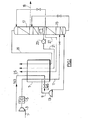
- integrated process for the separation of air by cryogenic distillation and liquefaction of natural gas (NG) in which at least part of the refrigeration required to liquefy the natural gas is derived from at least one cryogenic air distillation plant comprising a main heat exchanger (7) and distillation columns (15, 17), wherein the natural gas liquefies by indirect heat exchange in a heat exchanger (7, 32) with a cold fluid, the cold fluid (21, 26) being sent to the heat exchanger at least partially in liquid form and undergoing at least a partial vaporization in the heat exchanger.
- Process according to Claim 1 wherein isentropic expansion provides the refrigeration for the liquefaction of the natural gas.
- Process according to Claim 1 or 2 wherein the air separation unit comprises a double column (15, 17), with a thermally linked medium pressure column and low pressure column and wherein air is expanded in a turbine (13) before being sent to the medium pressure column.
- Process according to any preceding claims wherein the natural gas is liquefied within the main heat exchanger (7) of a/the cryogenic air distillation plant, in which feed air (1) for the cryogenic air distillation plant is cooled to a temperature suitable for distillation and the cold fluid is at least one liquid stream (21), enriched in at least one of oxygen, nitrogen and argon with respect to air, which vaporises in the main heat exchanger.
- Process according to Claim 4 wherein all the air (1) to be separated in the cryogenic air distillation plant is cooled in the main heat exchanger (7).
- Process according to Claim 5 wherein the natural gas (NG) is liquefied by heat exchange in an additional heat exchanger (32) other than the main heat exchanger (7) with at least one cold fluid (26) which has previously been cooled by a vaporising liquid (23) in the main heat exchanger of at least one air distillation plant.
- Process according to Ciaim 6 wherein the natural gas is liquefied by means of a closed circuit in which a cold fluid (26) flows, said cold fluid being warmed by heat exchange with the liquefying vaporising natural gas and cooled by heat exchange in the main heat exchanger (7).
- Process according to Claim 6 or 7 wherein the cold fluid is chosen from the group comprising nitrogen, argon, CF4, HCF3, methane, ethane, ethylene and propane.
- Process according to Claim 6, 7 or 8 wherein gaseous nitrogen (27) from the cryogenic air distillation plant is sent to the additional heat exchanger (32).
- Process according to any preceding claim wherein the cryogenic air distillation plant produces pressurised oxygen (21) for at least one GTL plant, a methanol plant or a DME plant fed by natural gas.
- Process according to any preceding claim wherein all of the refrigeration required to liquefy the natural gas (NG, 25) is derived from a single cryogenic air distillation plant, the columns of the plant, the main heat exchanger and the further heat exchanger being situated within a single cold box.
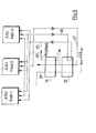
- Process according to any preceding claim wherein part of the refrigeration required to liquefy the natural gas is derived from at least two cryogenic air distillation plants (ASU), each comprising a main heat exchanger (7) and distillation columns (15, 17), said main heat exchanger and distillation columns being within the cold box, the part of the refrigeration required to liquefy the natural gas (25) being produced by vaporisation of at least one liquid stream, enriched in oxygen, nitrogen or argon, produced by one of the distillation columns, and the natural gas liquefies by heat exchange in a further heat exchanger by heat exchange with a cold fluid (26) removed from each cryogenic air distillation plant.
- Process according to Claim 12 wherein the natural gas prior to undergoing indirect heat exchange with said cold fluid (26) is at least partially precooled at a temperature below 0°C by indirect heat exchange with at least one fluid (40) not derived from any cryogenic air distillation plant.
- Process according to Claim 13 wherein said fluid(s) (40) not derived from any cryogenic air distillation plant comprises propane.
- Integrated apparatus for the separation of air by cryogenic distillation and liquefaction of natural gas in which at least part of the refrigeration required to liquefy the natural gas is derived from at least one cryogenic air distillation plant comprising a main heat exchanger (7) and distillation columns (15, 17) , comprising means for sending natural gas (25, NG) and a cold fluid (21, 26) at least partially in liquid form to a heat exchanger (7, 32), means for removing liquefied natural gas (LNG) from the heat exchanger and means for removing at least partially vaporised cold fluid from the heat exchanger.
- Apparatus according to Claim 15 wherein isentropic expansion provides the refrigeration for the liquefaction of the natural gas.
- Apparatus according to Claim 15 or 16 wherein the air separation unit comprises a double column (15, 17), with a thermally linked medium pressure column and low pressure column and a turbine (13) in which air is expanded and means for sending the expanded air to the medium pressure column (15).
- Apparatus according to any of Claims 15 to 17 comprising means for sending the natural gas to be liquefied to the main heat exchanger (7) of a/the cryogenic air distillation plant, and wherein the cold fluid is at least one liquid stream (21), enriched in at least one of oxygen, nitrogen and argon with respect to air, which vaporises in the main heat exchanger.
- Apparatus according to any of Claims 15 to 18 comprising means for sending all the air (1) to be separated to the main heat exchanger (7).
- Apparatus according to Claim 15 or 16 comprising an additional heat exchanger (32) other than the main heat exchanger (7) and means for sending the natural gas to be liquefied and at least one cold fluid (26) which has previously been cooled by a vaporising liquid (21) in the main heat exchanger (7) of at least one air distillation plant to the additional heat exchanger.
- Apparatus according to Claim 20 comprising a closed circuit passing through the main and additional heat exchangers (7, 32) in which the at least one cold fluid (26) flows.
- Apparatus according to Claim 20 or 21 comprising means for sending gaseous nitrogen (27) from the at least one cryogenic air distillation plant to the additional heat exchanger (32).
- Apparatus according to any of Claims 15 to 22 comprising means for sending pressunsed oxygen (21) from the cryogenic air distillation plant to at least one of a GTL plant, a methanol plant and a DME plant fed by natural gas.
- Apparatus according to any of Claims 15 to 23 wherein all of the refrigeration required to liquefy the natural gas is derived from a single cryogenic air distillation plant, the columns of the plant, the main heat exchanger and the further heat exchanger being situated within a single cold box.
- Apparatus according to any of Claims 15 to 23 wherein part of the refrigeration required to liquefy the natural gas is derived from at least two cryogenic air distillation plants, each comprising a main heat exchanger and distillation columns, said main heat exchanger and distillation columns being within the cold box, the part of the refrigeration required to liquefy the natural gas being produced by vaporisation of at least one liquid stream, enriched in oxygen, nitrogen or argon, produced by one of the distillation columns, and the natural gas liquefies by heat exchange in a further heat exchanger (32) by heat exchange with a cold fluid (26) removed from each cryogenic air distillation plant.
- Apparatus according to Claim 25 comprising means (34) for precooling the natural gas prior to undergoing indirect heat exchange with said cold fluid.
- Apparatus according to Claim 26 wherein said means for precooling comprises a heat exchanger (34) and means for sending propane (40) to the heat exchanger.
Applications Claiming Priority (4)
| Application Number | Priority Date | Filing Date | Title |
|---|---|---|---|
| US423039 | 1995-04-17 | ||
| US42303902P | 2002-11-01 | 2002-11-01 | |
| US10/681,632 US7143606B2 (en) | 2002-11-01 | 2003-10-08 | Combined air separation natural gas liquefaction plant |
| US681632 | 2003-10-08 |
Publications (2)
| Publication Number | Publication Date |
|---|---|
| EP1435497A2 true EP1435497A2 (en) | 2004-07-07 |
| EP1435497A3 EP1435497A3 (en) | 2005-04-20 |
Family
ID=32179969
Family Applications (1)
| Application Number | Title | Priority Date | Filing Date |
|---|---|---|---|
| EP03078262A Withdrawn EP1435497A3 (en) | 2002-11-01 | 2003-10-16 | Combined air separation and natural gas liquefaction plant |
Country Status (4)
| Country | Link |
|---|---|
| US (1) | US7143606B2 (en) |
| EP (1) | EP1435497A3 (en) |
| JP (1) | JP2004156899A (en) |
| CN (1) | CN1501044A (en) |
Cited By (4)
| Publication number | Priority date | Publication date | Assignee | Title |
|---|---|---|---|---|
| EP1544559A1 (en) * | 2003-12-20 | 2005-06-22 | Linde AG | Process and device for the cryogenic separation of air |
| CN105308404A (en) * | 2013-03-27 | 2016-02-03 | 高维有限公司 | Method and apparatus in a cryogenic liquefaction process |
| EP2880267B1 (en) | 2012-08-02 | 2016-07-20 | Linde Aktiengesellschaft | Method and device for generating electrical energy |
| WO2017098099A1 (en) | 2015-12-07 | 2017-06-15 | L'air Liquide, Societe Anonyme Pour L'etude Et L'exploitation Des Procedes Georges Claude | Method for liquefying natural gas and nitrogen |
Families Citing this family (120)
| Publication number | Priority date | Publication date | Assignee | Title |
|---|---|---|---|---|
| FR2851330B1 (en) * | 2003-02-13 | 2006-01-06 | Air Liquide | PROCESS AND PLANT FOR THE PRODUCTION OF A GASEOUS AND HIGH PRESSURE PRODUCTION OF AT LEAST ONE FLUID SELECTED AMONG OXYGEN, ARGON AND NITROGEN BY CRYOGENIC DISTILLATION OF AIR |
| US7272954B2 (en) * | 2004-07-14 | 2007-09-25 | L'air Liquide, Societe Anonyme A Directoire Et Conseil De Surveillance Pour L'etude Et L'exploitation Des Proceded Georges Claude | Low temperature air separation process for producing pressurized gaseous product |
| CN101027526B (en) * | 2004-09-22 | 2010-12-08 | 弗劳尔科技公司 | Arrangement and method for simultaneous LPG and power generation |
| US7437889B2 (en) * | 2006-01-11 | 2008-10-21 | Air Products And Chemicals, Inc. | Method and apparatus for producing products from natural gas including helium and liquefied natural gas |
| US7552599B2 (en) * | 2006-04-05 | 2009-06-30 | Air Products And Chemicals, Inc. | Air separation process utilizing refrigeration extracted from LNG for production of liquid oxygen |
| CN100441990C (en) * | 2006-08-03 | 2008-12-10 | 西安交通大学 | A Small Natural Gas Liquefaction Plant Using Air Separation Refrigeration System |
| EP1939564A1 (en) * | 2006-12-26 | 2008-07-02 | Repsol Ypf S.A. | Process to obtain liquefied natural gas |
| US20080250814A1 (en) * | 2007-04-10 | 2008-10-16 | Marut Todd P | Dehazing a lubes product by integrating an air separation unit with the dehazing process |
| WO2009120779A2 (en) | 2008-03-28 | 2009-10-01 | Exxonmobil Upstream Research Company | Low emission power generation and hydrocarbon recovery systems and methods |
| AU2009228062B2 (en) | 2008-03-28 | 2014-01-16 | Exxonmobil Upstream Research Company | Low emission power generation and hydrocarbon recovery systems and methods |
| US9714789B2 (en) * | 2008-09-10 | 2017-07-25 | Praxair Technology, Inc. | Air separation refrigeration supply method |
| EA026915B1 (en) | 2008-10-14 | 2017-05-31 | Эксонмобил Апстрим Рисерч Компани | Methods and systems for controlling the products of combustion |
| US9683703B2 (en) * | 2009-08-18 | 2017-06-20 | Charles Edward Matar | Method of storing and transporting light gases |
| CA2777768C (en) | 2009-11-12 | 2016-06-07 | Exxonmobil Upstream Research Company | Low emission power generation and hydrocarbon recovery systems and methods |
| DE102010012920A1 (en) * | 2010-03-26 | 2011-09-29 | Linde Aktiengesellschaft | Apparatus for the cryogenic separation of air |
| US20110259044A1 (en) * | 2010-04-22 | 2011-10-27 | Baudat Ned P | Method and apparatus for producing liquefied natural gas |
| US20120000242A1 (en) * | 2010-04-22 | 2012-01-05 | Baudat Ned P | Method and apparatus for storing liquefied natural gas |
| CN101846436A (en) * | 2010-05-27 | 2010-09-29 | 中国海洋石油总公司 | Full-liquid air separation device using cold energy of liquefied natural gas (LNG) |
| EA029336B1 (en) | 2010-07-02 | 2018-03-30 | Эксонмобил Апстрим Рисерч Компани | Systems and method of generating power by stoichiometric combustion with enriched air and exhaust gas recirculation |
| CN102971508B (en) | 2010-07-02 | 2016-06-01 | 埃克森美孚上游研究公司 | CO2 separation system and method for separating CO2 |
| US9732673B2 (en) | 2010-07-02 | 2017-08-15 | Exxonmobil Upstream Research Company | Stoichiometric combustion with exhaust gas recirculation and direct contact cooler |
| BR112012031153A2 (en) | 2010-07-02 | 2016-11-08 | Exxonmobil Upstream Res Co | low emission triple-cycle power generation systems and methods |
| US20120017639A1 (en) * | 2010-07-21 | 2012-01-26 | Synfuels International, Inc. | Methods and systems for storing and transporting gases |
| TWI563165B (en) | 2011-03-22 | 2016-12-21 | Exxonmobil Upstream Res Co | Power generation system and method for generating power |
| TWI563166B (en) | 2011-03-22 | 2016-12-21 | Exxonmobil Upstream Res Co | Integrated generation systems and methods for generating power |
| TWI593872B (en) | 2011-03-22 | 2017-08-01 | 艾克頌美孚上游研究公司 | Integrated system and method of generating power |
| TWI564474B (en) | 2011-03-22 | 2017-01-01 | 艾克頌美孚上游研究公司 | Integrated systems for controlling stoichiometric combustion in turbine systems and methods of generating power using the same |
| FR2977014B1 (en) * | 2011-06-24 | 2016-04-15 | Saipem Sa | PROCESS FOR THE LIQUEFACTION OF NATURAL GAS WITH A MIXTURE OF REFRIGERANT GAS. |
| EP2551619A1 (en) * | 2011-07-26 | 2013-01-30 | Linde Aktiengesellschaft | Method and device for extracting pressurised oxygen and pressurised nitrogen by cryogenic decomposition of air |
| EP2568463A1 (en) * | 2011-09-08 | 2013-03-13 | Thomson Licensing | Methods and devices for protecting digital objects through format preserving coding |
| CN102374754B (en) * | 2011-09-24 | 2015-08-19 | 辽宁哈深冷气体液化设备有限公司 | The Apparatus and method for of liquified natural gas and carbon monoxide is produced from coke-stove gas |
| CN103075868B (en) * | 2011-10-25 | 2015-09-23 | 中国石油天然气股份有限公司 | A kind of natural gas liquefaction system and liquefaction method |
| CN103075869B (en) * | 2011-10-25 | 2015-09-23 | 中国石油天然气股份有限公司 | A natural gas dual refrigerant liquefaction system and liquefaction method |
| CN104428490B (en) | 2011-12-20 | 2018-06-05 | 埃克森美孚上游研究公司 | The coal bed methane production of raising |
| US9353682B2 (en) | 2012-04-12 | 2016-05-31 | General Electric Company | Methods, systems and apparatus relating to combustion turbine power plants with exhaust gas recirculation |
| US9784185B2 (en) | 2012-04-26 | 2017-10-10 | General Electric Company | System and method for cooling a gas turbine with an exhaust gas provided by the gas turbine |
| US10273880B2 (en) | 2012-04-26 | 2019-04-30 | General Electric Company | System and method of recirculating exhaust gas for use in a plurality of flow paths in a gas turbine engine |
| US9599070B2 (en) | 2012-11-02 | 2017-03-21 | General Electric Company | System and method for oxidant compression in a stoichiometric exhaust gas recirculation gas turbine system |
| US9574496B2 (en) | 2012-12-28 | 2017-02-21 | General Electric Company | System and method for a turbine combustor |
| US9708977B2 (en) | 2012-12-28 | 2017-07-18 | General Electric Company | System and method for reheat in gas turbine with exhaust gas recirculation |
| US9631815B2 (en) | 2012-12-28 | 2017-04-25 | General Electric Company | System and method for a turbine combustor |
| US10161312B2 (en) | 2012-11-02 | 2018-12-25 | General Electric Company | System and method for diffusion combustion with fuel-diluent mixing in a stoichiometric exhaust gas recirculation gas turbine system |
| US10107495B2 (en) | 2012-11-02 | 2018-10-23 | General Electric Company | Gas turbine combustor control system for stoichiometric combustion in the presence of a diluent |
| US10215412B2 (en) | 2012-11-02 | 2019-02-26 | General Electric Company | System and method for load control with diffusion combustion in a stoichiometric exhaust gas recirculation gas turbine system |
| US9803865B2 (en) | 2012-12-28 | 2017-10-31 | General Electric Company | System and method for a turbine combustor |
| US9611756B2 (en) | 2012-11-02 | 2017-04-04 | General Electric Company | System and method for protecting components in a gas turbine engine with exhaust gas recirculation |
| US9869279B2 (en) | 2012-11-02 | 2018-01-16 | General Electric Company | System and method for a multi-wall turbine combustor |
| US10208677B2 (en) | 2012-12-31 | 2019-02-19 | General Electric Company | Gas turbine load control system |
| US9581081B2 (en) | 2013-01-13 | 2017-02-28 | General Electric Company | System and method for protecting components in a gas turbine engine with exhaust gas recirculation |
| CN103162512B (en) * | 2013-01-27 | 2015-06-10 | 南京瑞柯徕姆环保科技有限公司 | Air separation plant used for preparing oxygen and nitrogen in identical-pressure separation mode |
| US9512759B2 (en) | 2013-02-06 | 2016-12-06 | General Electric Company | System and method for catalyst heat utilization for gas turbine with exhaust gas recirculation |
| US9938861B2 (en) | 2013-02-21 | 2018-04-10 | Exxonmobil Upstream Research Company | Fuel combusting method |
| TW201502356A (en) | 2013-02-21 | 2015-01-16 | Exxonmobil Upstream Res Co | Reducing oxygen in a gas turbine exhaust |
| WO2014133406A1 (en) | 2013-02-28 | 2014-09-04 | General Electric Company | System and method for a turbine combustor |
| US9618261B2 (en) | 2013-03-08 | 2017-04-11 | Exxonmobil Upstream Research Company | Power generation and LNG production |
| CN105008499A (en) | 2013-03-08 | 2015-10-28 | 埃克森美孚上游研究公司 | Power generation and methane recovery from methane hydrates |
| US20140250945A1 (en) | 2013-03-08 | 2014-09-11 | Richard A. Huntington | Carbon Dioxide Recovery |
| TW201500635A (en) | 2013-03-08 | 2015-01-01 | Exxonmobil Upstream Res Co | Processing exhaust for use in enhanced oil recovery |
| US20140352353A1 (en) * | 2013-05-28 | 2014-12-04 | Robert S. Wissolik | Natural Gas Liquefaction System for Producing LNG and Merchant Gas Products |
| US9631542B2 (en) | 2013-06-28 | 2017-04-25 | General Electric Company | System and method for exhausting combustion gases from gas turbine engines |
| TWI654368B (en) | 2013-06-28 | 2019-03-21 | 美商艾克頌美孚上游研究公司 | System, method and media for controlling exhaust gas flow in an exhaust gas recirculation gas turbine system |
| US9835089B2 (en) | 2013-06-28 | 2017-12-05 | General Electric Company | System and method for a fuel nozzle |
| US9617914B2 (en) | 2013-06-28 | 2017-04-11 | General Electric Company | Systems and methods for monitoring gas turbine systems having exhaust gas recirculation |
| US9903588B2 (en) | 2013-07-30 | 2018-02-27 | General Electric Company | System and method for barrier in passage of combustor of gas turbine engine with exhaust gas recirculation |
| US9587510B2 (en) | 2013-07-30 | 2017-03-07 | General Electric Company | System and method for a gas turbine engine sensor |
| US9951658B2 (en) | 2013-07-31 | 2018-04-24 | General Electric Company | System and method for an oxidant heating system |
| CN105705893A (en) * | 2013-09-10 | 2016-06-22 | 乔治洛德方法研究和开发液化空气有限公司 | Method and device for separation at sub-ambient temperature |
| US10030588B2 (en) | 2013-12-04 | 2018-07-24 | General Electric Company | Gas turbine combustor diagnostic system and method |
| US9752458B2 (en) | 2013-12-04 | 2017-09-05 | General Electric Company | System and method for a gas turbine engine |
| KR101571514B1 (en) | 2013-12-31 | 2015-11-25 | 대우조선해양 주식회사 | Integrated cooling apparatus for DME FPSO |
| US10227920B2 (en) | 2014-01-15 | 2019-03-12 | General Electric Company | Gas turbine oxidant separation system |
| US9915200B2 (en) | 2014-01-21 | 2018-03-13 | General Electric Company | System and method for controlling the combustion process in a gas turbine operating with exhaust gas recirculation |
| US9863267B2 (en) | 2014-01-21 | 2018-01-09 | General Electric Company | System and method of control for a gas turbine engine |
| US10079564B2 (en) | 2014-01-27 | 2018-09-18 | General Electric Company | System and method for a stoichiometric exhaust gas recirculation gas turbine system |
| US10047633B2 (en) | 2014-05-16 | 2018-08-14 | General Electric Company | Bearing housing |
| US9885290B2 (en) | 2014-06-30 | 2018-02-06 | General Electric Company | Erosion suppression system and method in an exhaust gas recirculation gas turbine system |
| US10060359B2 (en) | 2014-06-30 | 2018-08-28 | General Electric Company | Method and system for combustion control for gas turbine system with exhaust gas recirculation |
| US10655542B2 (en) | 2014-06-30 | 2020-05-19 | General Electric Company | Method and system for startup of gas turbine system drive trains with exhaust gas recirculation |
| US9869247B2 (en) | 2014-12-31 | 2018-01-16 | General Electric Company | Systems and methods of estimating a combustion equivalence ratio in a gas turbine with exhaust gas recirculation |
| US9819292B2 (en) | 2014-12-31 | 2017-11-14 | General Electric Company | Systems and methods to respond to grid overfrequency events for a stoichiometric exhaust recirculation gas turbine |
| US10788212B2 (en) | 2015-01-12 | 2020-09-29 | General Electric Company | System and method for an oxidant passageway in a gas turbine system with exhaust gas recirculation |
| US10094566B2 (en) | 2015-02-04 | 2018-10-09 | General Electric Company | Systems and methods for high volumetric oxidant flow in gas turbine engine with exhaust gas recirculation |
| US10253690B2 (en) | 2015-02-04 | 2019-04-09 | General Electric Company | Turbine system with exhaust gas recirculation, separation and extraction |
| US10316746B2 (en) | 2015-02-04 | 2019-06-11 | General Electric Company | Turbine system with exhaust gas recirculation, separation and extraction |
| US10267270B2 (en) | 2015-02-06 | 2019-04-23 | General Electric Company | Systems and methods for carbon black production with a gas turbine engine having exhaust gas recirculation |
| US10145269B2 (en) | 2015-03-04 | 2018-12-04 | General Electric Company | System and method for cooling discharge flow |
| US10480792B2 (en) | 2015-03-06 | 2019-11-19 | General Electric Company | Fuel staging in a gas turbine engine |
| TWI641789B (en) | 2015-07-10 | 2018-11-21 | 艾克頌美孚上游研究公司 | System and method for producing liquefied nitrogen using liquefied natural gas |
| TWI608206B (en) | 2015-07-15 | 2017-12-11 | 艾克頌美孚上游研究公司 | Liquefied natural gas (LNG) production system with increased efficiency by pre-cooling the natural gas supply stream |
| TWI606221B (en) | 2015-07-15 | 2017-11-21 | 艾克頌美孚上游研究公司 | Liquefied natural gas production system and method with greenhouse gas removal |
| CN108291767B (en) | 2015-12-14 | 2021-02-19 | 埃克森美孚上游研究公司 | Method for liquefaction of natural gas on LNG carriers storing liquid nitrogen |
| WO2017105679A1 (en) | 2015-12-14 | 2017-06-22 | Exxonmobil Upstream Research Company | Method and system for separating nitrogen from liquefied natural gas using liquefied nitrogen |
| US10281203B2 (en) * | 2016-08-05 | 2019-05-07 | L'air Liquide Societe Anonyme Pour L'etude Et L'exploitation Des Procedes Georges Claude | Method for liquefaction of industrial gas by integration of methanol plant and air separation unit |
| US10288346B2 (en) * | 2016-08-05 | 2019-05-14 | L'air Liquide Societe Anonyme Pour L'etude Et L'exploitation Des Procedes Georges Claude | Method for liquefaction of industrial gas by integration of methanol plant and air separation unit |
| CN106595219A (en) * | 2016-11-03 | 2017-04-26 | 天道新能源科技有限公司 | System for preparing LNG (Liquefied Natural Gas) by using cold supplied by liquefied air |
| US10612842B2 (en) | 2016-11-18 | 2020-04-07 | L'air Liquide Societe Anonyme Pour L'etude Et L'exploitation Des Procedes Georges Claude | LNG integration with cryogenic unit |
| EA201991821A1 (en) | 2017-01-31 | 2020-01-14 | Неаршор Нэчрал Гэс, Ллк | VEHICLE FOR STORAGE AND TRANSPORT OF COMPRATED NATURAL GAS |
| WO2018222230A1 (en) | 2017-02-24 | 2018-12-06 | Exxonmobil Upstream Research Company | Method of purging a dual purpose lng/lin storage tank |
| CN108826833B (en) * | 2018-05-09 | 2020-05-26 | 常州大学 | Natural gas impurity separation and recovery device |
| US11536510B2 (en) | 2018-06-07 | 2022-12-27 | Exxonmobil Upstream Research Company | Pretreatment and pre-cooling of natural gas by high pressure compression and expansion |
| WO2020036711A1 (en) | 2018-08-14 | 2020-02-20 | Exxonmobil Upstream Research Company | Conserving mixed refrigerant in natural gas liquefaction facilities |
| MY209447A (en) | 2018-08-22 | 2025-07-09 | Exxonmobil Upstream Res Co | Heat exchanger configuration for a high pressure expander process and a method of natural gas liquefaction using the same |
| US11555651B2 (en) | 2018-08-22 | 2023-01-17 | Exxonmobil Upstream Research Company | Managing make-up gas composition variation for a high pressure expander process |
| EP3841344A1 (en) | 2018-08-22 | 2021-06-30 | ExxonMobil Upstream Research Company | Primary loop start-up method for a high pressure expander process |
| WO2020106394A1 (en) | 2018-11-20 | 2020-05-28 | Exxonmobil Upstream Research Company | Poly refrigerated integrated cycle operation using solid-tolerant heat exchangers |
| WO2020106397A1 (en) | 2018-11-20 | 2020-05-28 | Exxonmobil Upstream Research Company | Methods and apparatus for improving multi-plate scraped heat exchangers |
| CA3123235C (en) | 2019-01-30 | 2025-02-11 | ExxonMobil Technology and Engineering Company | Methods for removal of moisture from lng refrigerant |
| US11668524B2 (en) | 2019-01-30 | 2023-06-06 | Exxonmobil Upstream Research Company | Methods for removal of moisture from LNG refrigerant |
| US11465093B2 (en) | 2019-08-19 | 2022-10-11 | Exxonmobil Upstream Research Company | Compliant composite heat exchangers |
| US20210063083A1 (en) | 2019-08-29 | 2021-03-04 | Exxonmobil Upstream Research Company | Liquefaction of Production Gas |
| EP4031820A1 (en) | 2019-09-19 | 2022-07-27 | Exxonmobil Upstream Research Company (EMHC-N1-4A-607) | Pretreatment, pre-cooling, and condensate recovery of natural gas by high pressure compression and expansion |
| WO2021055020A1 (en) | 2019-09-19 | 2021-03-25 | Exxonmobil Upstream Research Company | Pretreatment and pre-cooling of natural gas by high pressure compression and expansion |
| EP4031821A1 (en) | 2019-09-19 | 2022-07-27 | ExxonMobil Upstream Research Company | Pretreatment and pre-cooling of natural gas by high pressure compression and expansion |
| WO2021055074A1 (en) | 2019-09-20 | 2021-03-25 | Exxonmobil Upstream Research Company | Removal of acid gases from a gas stream, with o2 enrichment for acid gas capture and sequestration |
| US11808411B2 (en) | 2019-09-24 | 2023-11-07 | ExxonMobil Technology and Engineering Company | Cargo stripping features for dual-purpose cryogenic tanks on ships or floating storage units for LNG and liquid nitrogen |
| US20220034584A1 (en) * | 2020-07-30 | 2022-02-03 | L'Air Liquide, Société Anonyme pour l'Etude et l'Exploitation des Procédés Georges Claude | Large liquid oxygen and liquefied natural gas production process |
| US20230017256A1 (en) * | 2021-07-19 | 2023-01-19 | L'Air Liquide, Société Anonyme pour l'Etude et l'Exploitation des Procédés Georges Claude | Integrated multicomponent refrigerant and air separation process for producing liquid oxygen |
| KR102622554B1 (en) * | 2021-08-18 | 2024-01-11 | 부산대학교 산학협력단 | Liquefaction system for natural gas, ship comprising the same, liquefaction process for natural gas and air |
| CN114017993B (en) * | 2022-01-06 | 2022-06-07 | 杭氧集团股份有限公司 | Device and method for producing hydrogen and byproduct oxygen by utilizing green electrolysis water |
| WO2023215292A1 (en) * | 2022-05-02 | 2023-11-09 | Nearshore Natural Gas, Llc | Cryogenic liquefaction system and method |
Family Cites Families (18)
| Publication number | Priority date | Publication date | Assignee | Title |
|---|---|---|---|---|
| LU37632A1 (en) * | 1955-08-29 | |||
| GB975729A (en) * | 1963-11-12 | 1964-11-18 | Conch Int Methane Ltd | Process for the separation of nitrogen and oxygen from air by fractional distillation |
| GB1135871A (en) * | 1965-06-29 | 1968-12-04 | Air Prod & Chem | Liquefaction of natural gas |
| FR2060184B1 (en) * | 1969-09-10 | 1973-11-16 | Air Liquide | |
| US3763658A (en) | 1970-01-12 | 1973-10-09 | Air Prod & Chem | Combined cascade and multicomponent refrigeration system and method |
| FR2122307B1 (en) | 1971-01-19 | 1975-01-17 | Denis Louis | |
| GB8505930D0 (en) | 1985-03-07 | 1985-04-11 | Ncl Consulting Engineers | Gas handling |
| US5220798A (en) * | 1990-09-18 | 1993-06-22 | Teisan Kabushiki Kaisha | Air separating method using external cold source |
| US5137558A (en) * | 1991-04-26 | 1992-08-11 | Air Products And Chemicals, Inc. | Liquefied natural gas refrigeration transfer to a cryogenics air separation unit using high presure nitrogen stream |
| US5390499A (en) | 1993-10-27 | 1995-02-21 | Liquid Carbonic Corporation | Process to increase natural gas methane content |
| AUPM485694A0 (en) | 1994-04-05 | 1994-04-28 | Bhp Petroleum Pty. Ltd. | Liquefaction process |
| US5615561A (en) * | 1994-11-08 | 1997-04-01 | Williams Field Services Company | LNG production in cryogenic natural gas processing plants |
| NO970322L (en) | 1997-01-24 | 1998-07-27 | Norske Stats Oljeselskap | Process and integrated processing plant for the production of synfuel, LNG and electric power |
| JP3610246B2 (en) | 1998-10-29 | 2005-01-12 | 大阪瓦斯株式会社 | LNG boil-off gas reliquefaction and air separation integrated device |
| US6131407A (en) * | 1999-03-04 | 2000-10-17 | Wissolik; Robert | Natural gas letdown liquefaction system |
| DE19920312A1 (en) | 1999-05-03 | 2000-11-09 | Linde Ag | Process for liquefying a hydrocarbon-rich stream comprises liquefying a partial stream against a stream from a cryogenic air decomposition plant on a corresponding temperature level |
| DE19923640A1 (en) | 1999-05-22 | 2000-11-30 | Messer Griesheim Gmbh | Method and device for liquefying natural gas |
| JP2002295799A (en) * | 2001-04-03 | 2002-10-09 | Kobe Steel Ltd | Method and system for treating liquefied natural gas and nitrogen |
-
2003
- 2003-10-08 US US10/681,632 patent/US7143606B2/en not_active Expired - Lifetime
- 2003-10-16 EP EP03078262A patent/EP1435497A3/en not_active Withdrawn
- 2003-10-31 CN CNA200310103133A patent/CN1501044A/en active Pending
- 2003-10-31 JP JP2003372784A patent/JP2004156899A/en active Pending
Cited By (6)
| Publication number | Priority date | Publication date | Assignee | Title |
|---|---|---|---|---|
| EP1544559A1 (en) * | 2003-12-20 | 2005-06-22 | Linde AG | Process and device for the cryogenic separation of air |
| EP2880267B1 (en) | 2012-08-02 | 2016-07-20 | Linde Aktiengesellschaft | Method and device for generating electrical energy |
| CN105308404A (en) * | 2013-03-27 | 2016-02-03 | 高维有限公司 | Method and apparatus in a cryogenic liquefaction process |
| CN105308404B (en) * | 2013-03-27 | 2018-02-23 | 高维有限公司 | Method and apparatus in low-temperature liquefaction technique |
| WO2017098099A1 (en) | 2015-12-07 | 2017-06-15 | L'air Liquide, Societe Anonyme Pour L'etude Et L'exploitation Des Procedes Georges Claude | Method for liquefying natural gas and nitrogen |
| US10890375B2 (en) | 2015-12-07 | 2021-01-12 | L'Air Liquide, Société Anonyme pour l'Etude et l'Exploitation des Procédés Georges Claude | Method for liquefying natural gas and nitrogen |
Also Published As
| Publication number | Publication date |
|---|---|
| EP1435497A3 (en) | 2005-04-20 |
| US20040083756A1 (en) | 2004-05-06 |
| CN1501044A (en) | 2004-06-02 |
| JP2004156899A (en) | 2004-06-03 |
| US7143606B2 (en) | 2006-12-05 |
Similar Documents
| Publication | Publication Date | Title |
|---|---|---|
| US7143606B2 (en) | Combined air separation natural gas liquefaction plant | |
| CA2291415C (en) | Dual mixed refrigerant cycle for gas liquefaction | |
| US6253574B1 (en) | Method for liquefying a stream rich in hydrocarbons | |
| AU733788B2 (en) | Use of a turboexpander cycle in liquefied natural gas process | |
| US9625208B2 (en) | Method and apparatus for liquefying a gaseous hydrocarbon stream | |
| AU2007253406B2 (en) | Method and apparatus for treating a hydrocarbon stream | |
| CA3101931C (en) | Pretreatment and pre-cooling of natural gas by high pressure compression and expansion | |
| US11815308B2 (en) | Pretreatment and pre-cooling of natural gas by high pressure compression and expansion | |
| US11806639B2 (en) | Pretreatment and pre-cooling of natural gas by high pressure compression and expansion | |
| JP7326485B2 (en) | Pretreatment, pre-cooling and condensate recovery of natural gas by high pressure compression and expansion | |
| KR20250056138A (en) | System and method for cooling a fluid containing hydrogen or helium | |
| CN101443616B (en) | Method and device for distributing liquefied hydrocarbon gas | |
| EP4457478A2 (en) | Process for precooling hydrogen for liquefaction with supplement liquid nitrogen |
Legal Events
| Date | Code | Title | Description |
|---|---|---|---|
| PUAI | Public reference made under article 153(3) epc to a published international application that has entered the european phase |
Free format text: ORIGINAL CODE: 0009012 |
|
| AK | Designated contracting states |
Kind code of ref document: A2 Designated state(s): AT BE BG CH CY CZ DE DK EE ES FI FR GB GR HU IE IT LI LU MC NL PT RO SE SI SK TR |
|
| AX | Request for extension of the european patent |
Extension state: AL LT LV MK |
|
| PUAL | Search report despatched |
Free format text: ORIGINAL CODE: 0009013 |
|
| AK | Designated contracting states |
Kind code of ref document: A3 Designated state(s): AT BE BG CH CY CZ DE DK EE ES FI FR GB GR HU IE IT LI LU MC NL PT RO SE SI SK TR |
|
| AX | Request for extension of the european patent |
Extension state: AL LT LV MK |
|
| 17P | Request for examination filed |
Effective date: 20051020 |
|
| AKX | Designation fees paid |
Designated state(s): DE FR GB |
|
| 17Q | First examination report despatched |
Effective date: 20070123 |
|
| RAP1 | Party data changed (applicant data changed or rights of an application transferred) |
Owner name: L'AIR LIQUIDE, SOCIETE ANONYME POUR L'ETUDE ET L'E |
|
| RAP1 | Party data changed (applicant data changed or rights of an application transferred) |
Owner name: L'AIR LIQUIDE, SOCIETE ANONYME POUR L'ETUDE ET L'E |
|
| STAA | Information on the status of an ep patent application or granted ep patent |
Free format text: STATUS: THE APPLICATION IS DEEMED TO BE WITHDRAWN |
|
| 18D | Application deemed to be withdrawn |
Effective date: 20070803 |