EP1434974B1 - Dispositif et procédé pour determiner le niveau de remplissage d'une substance dans un contenant - Google Patents
Dispositif et procédé pour determiner le niveau de remplissage d'une substance dans un contenant Download PDFInfo
- Publication number
- EP1434974B1 EP1434974B1 EP02764889.8A EP02764889A EP1434974B1 EP 1434974 B1 EP1434974 B1 EP 1434974B1 EP 02764889 A EP02764889 A EP 02764889A EP 1434974 B1 EP1434974 B1 EP 1434974B1
- Authority
- EP
- European Patent Office
- Prior art keywords
- measuring
- control
- antenna
- signals
- evaluation unit
- Prior art date
- Legal status (The legal status is an assumption and is not a legal conclusion. Google has not performed a legal analysis and makes no representation as to the accuracy of the status listed.)
- Expired - Lifetime
Links
- 238000000034 method Methods 0.000 title claims description 18
- 239000000126 substance Substances 0.000 title 1
- 238000011156 evaluation Methods 0.000 claims description 33
- 238000012360 testing method Methods 0.000 claims description 22
- 230000005540 biological transmission Effects 0.000 claims description 17
- 230000005855 radiation Effects 0.000 claims description 6
- 230000007257 malfunction Effects 0.000 claims description 3
- 238000005259 measurement Methods 0.000 description 39
- 239000000463 material Substances 0.000 description 11
- 239000000047 product Substances 0.000 description 6
- 239000000758 substrate Substances 0.000 description 4
- 230000015572 biosynthetic process Effects 0.000 description 3
- 238000009434 installation Methods 0.000 description 3
- 230000000903 blocking effect Effects 0.000 description 2
- 238000010586 diagram Methods 0.000 description 2
- 238000012935 Averaging Methods 0.000 description 1
- 238000013459 approach Methods 0.000 description 1
- 239000013590 bulk material Substances 0.000 description 1
- 238000009833 condensation Methods 0.000 description 1
- 230000005494 condensation Effects 0.000 description 1
- 238000001514 detection method Methods 0.000 description 1
- 238000011161 development Methods 0.000 description 1
- 238000005293 physical law Methods 0.000 description 1
- 238000005070 sampling Methods 0.000 description 1
- 239000007787 solid Substances 0.000 description 1
- 239000012265 solid product Substances 0.000 description 1
Images


Classifications
-
- G—PHYSICS
- G01—MEASURING; TESTING
- G01F—MEASURING VOLUME, VOLUME FLOW, MASS FLOW OR LIQUID LEVEL; METERING BY VOLUME
- G01F23/00—Indicating or measuring liquid level or level of fluent solid material, e.g. indicating in terms of volume or indicating by means of an alarm
- G01F23/22—Indicating or measuring liquid level or level of fluent solid material, e.g. indicating in terms of volume or indicating by means of an alarm by measuring physical variables, other than linear dimensions, pressure or weight, dependent on the level to be measured, e.g. by difference of heat transfer of steam or water
- G01F23/28—Indicating or measuring liquid level or level of fluent solid material, e.g. indicating in terms of volume or indicating by means of an alarm by measuring physical variables, other than linear dimensions, pressure or weight, dependent on the level to be measured, e.g. by difference of heat transfer of steam or water by measuring the variations of parameters of electromagnetic or acoustic waves applied directly to the liquid or fluent solid material
- G01F23/284—Electromagnetic waves
Definitions
- the invention relates to an apparatus and a method for determining the level of a filling material in a container via a transit time method.
- Runtime methods such as the pulse radar method and the FMCW Radar Frequency Modulation Continuous Wave (FMCW) radar, exploit the physical law that the running distance of a measurement signal is equal to the product of its transit time and propagation speed.
- the running distance of the measuring signals corresponds to twice the distance between the antenna and the surface of the medium.
- the useful echo signal that is to say the signal reflected on the surface of the medium, and its running distance are determined on the basis of the so-called echo function or the digitized envelope.
- the envelope represents the amplitudes of the echo signals as a function of the distance 'antenna - surface of the medium'.
- the fill level itself results from the difference between the known distance of the antenna to the bottom of the container and the distance determined by the measurement of the surface of the medium to the antenna.
- level measuring devices are designed such that they emit the measurement signals as possible in a punctiform measuring range of the surface of the medium.
- this measuring range is in a direct extension to the longitudinal axis or to the rotationally symmetric axis of the antenna.
- Correspondingly configured fill level measuring devices provide reliable measurement data, as long as the longitudinal axis of the antenna is positioned at least approximately in the direction of the surface normal of the filling material.
- this positioning of the antenna is made difficult or even prevented, for example, when the lid of the container is curved or when the opening nozzle in which the antenna is mounted, is inclined relative to the surface of the medium.
- the invention has for its object to propose an apparatus and a method that allow a highly accurate measurement of the level of a product in a container via a transit time method.
- a transmitting unit the measuring signals via a patch antenna with a plurality of patches and at least one electronically switched Hauptabstrahl direction emits, wherein the main emission of the measuring signals either outside the surface normal of the medium lies or wherein the longitudinal axis of the antenna outside the surface normal of the medium and wherein the at least one main emission of the measuring signals is substantially in the direction of the surface normal of the medium, or the main emission directions of the measurement signals are chosen such that the measurement signals are emitted into at least two different measurement ranges located in the near field and / or in the far field of the transmitter unit; a receiving unit that receives the reflected echo signals in the at least one measuring range; a control / evaluation circuit, which determines the level and / or process or sensor-related disturbances inside the container based on the duration of the reflected echo signals.
- the transmitting / receiving unit can of course be an antenna.
- a first variant of the device according to the invention aims at controlling the antenna so that the measuring signals are radiated and reflected substantially in the direction of the surface normal of the filling material, independently of the installation of the antenna in the container lid or in the container wall.
- the longitudinal axis of the antenna is positioned substantially in the direction of the surface normal of the filling material.
- the antenna is z. B. digitally controlled so that the measurement signals scan / scan different areas of the surface of the medium or the container interior /. As a result of this sampling, information about the environment of the measuring range is provided.
- the second variant of the device according to the invention it is u.a. it is possible to detect unevennesses on the surface of the medium and to take this into account when determining the current filling level.
- the invention makes it possible to obtain information about the filling level in a first measuring cycle ( ⁇ far-field measurement) and, in a second measuring cycle, information about e.g. to get a buildup on the antenna ( ⁇ near field measurement).
- control / evaluation circuit electronically switches the patches so that the measurement signals have at least two mutually different main emission directions.
- the measurement signals targeted so that they are not on a Built-in, which is located in the container to be reflected.
- corresponding methods for targeted emission and reception of measurement signals have become known in radar technology under the term 'digital beamforming'.
- control / evaluation unit controls the patches so that the measuring ranges, in which the measurement signals impinge, lie in at least two mutually different areas of the surface of the medium.
- This variant makes it possible to make a statement about the bulk cone or the structure of the surface of the product in the case of solid bulk materials. Furthermore, this makes it possible to detect obstacles in the beam path and hide.
- An advantageous development of the device according to the invention proposes that the control / evaluation unit based on a plurality of measurement signals which have been reflected in different measurement ranges, the useful echo signal, ie to determine the reflected at the surface of the medium measurement signal. In the simplest case, this determination is made by averaging.
- the two aforementioned advantageous embodiments of the device according to the invention are essentially aimed at measurements in the far field of the antenna:
- built-in parts located in the far field or an irregularly shaped product surface can be taken into account in the determination of the current fill level.
- a very interesting embodiment of the device according to the invention is now aimed at obtaining and evaluating measured values from the far field and the near field of the antenna.
- control / evaluation unit based on measurement signals, which are reflected in a first measurement range, the useful echo signal determined and that the control / evaluation unit using measurement signals, which are reflected in at least a second measurement range, corrects the useful echo signal and / or performs a plausibility check and / or detects the cause of a malfunction, in particular a buildup at the transmitting / receiving unit, and / or detects a temporary or stationary disturbance inside the container or in the process and possibly taken into account in the filling level determination.
- the at least one transmitting / receiving unit emits or receives a transmission mode and a test mode, wherein the main emission directions of transmission mode and test mode are different from each other.
- a transmission mode with a pronounced forward lobe is also selected;
- test mode a mode is preferably selected which has pronounced side lobes.
- control / evaluation unit controls the transmitting / receiving unit in such a way that the transmission mode and the test mode are alternately transmitted or received; then both modes are evaluated independently.
- the filling level is determined on the basis of the transmission mode, while information is obtained on the basis of the test mode as to whether or not the antenna has formed.
- the control / evaluation unit activates the test mode only for predetermined time intervals.
- An alternative embodiment of the device according to the invention provides that the control / evaluation unit corrects the measurement signals of the Meßmodes due to the measurement signals of the test mode and / or that the control / evaluation unit, the measurement signals of the test mode for detecting stationary or temporary disturbances in the interior of the container attracts.
- the method according to the invention comprises the following method steps: measuring signals with different main emission directions are emitted via at least one patch antenna with a multiplicity of transmitting and / or receiving elements into at least two measuring ranges which are different from each other and which are located inside the container; Subsequently, the reflected in the different measuring ranges echo signals are detected; the detected echo signals are used to determine the fill level and / or to determine process- and / or sensor-related false echo signals.
- Fig. 1 shows a schematic representation of a first variant of the device according to the invention.
- the filling material 2 is stored in the container 1.
- the filling level of the filling material 2 in the container is determined by means of the filling level measuring device 6 via a transit time method.
- the antenna unit 11 with signal generating, transmitting and receiving unit is spatially offset from the control / evaluation unit 9 and the memory unit 10.
- the antenna unit 11 is mounted in the opening 5 in the lid 4 of the container 1. Via the antenna unit 11, measuring signals Tx, in particular microwaves, are radiated in the direction of the surface normal of the filling material 2. In the case shown, the antenna unit 11 is controlled electronically so that it emits measuring signals in two different measuring ranges A1, A2 on the surface 3 of the medium 2. The reflected echo signals Rx are received in the antenna unit 11. Based on the duration of the measurement signals Tx / echo signals Rx determines the control / evaluation unit 9 u.a. the current level of the contents 2 in the container. 1
- the antenna 11 can also be mounted such that the longitudinal axis 15 of the antenna 11 is not parallel to the antenna 11 Surface normal of the medium 3 is aligned. This is the case, as previously stated, when the antenna is mounted in a curved container lid 4.
- the main emission of the measurement signals Tx can be realized in the direction of the surface normal of the medium 2.
- patch antennas 16 have a plurality of defined transmitting and / or receiving elements 12, 13. Through targeted electronic interconnection of the elements 12, 13, measurement signals Tx can be generated with a wide variety of emission characteristics. Reference is made in this connection to the EP 1 076 244 A1 ,
- the area of a single transmitting and / or receiving element 12, 13 is small in comparison to the area of the substrate 14.
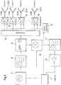
- the transmitting and / or receiving elements 12, 13 are represented by boxes. It goes without saying that each transmitting and / or receiving element 12, 13 can be connected individually, for example, in the substrate 14 correspondingly many holes are provided, through which the electrical contact takes place.
- a plurality of transmitting and / or receiving elements 12, 13 are combined to form functional blocks. So z. B. as in Fig. 2 shown, all arranged in the right part of the substrate transmitting and / or receiving elements 12, 13 and all arranged in the left part transmitting and / or receiving elements 12, 13 to be interconnected to form a functional block.
- the assignment is in Fig. 2 symbolically entered by one half of the transmitting and / or receiving elements 12 is marked with a cross.
- Fig. 4 shows a block diagram for the electronic circuit of 1, 2 ..., N transmitting / receiving elements 12, 13.
- the transmitting / receiving elements 12, 13 are, for example, the patches on one of the in Figs Fig. 2 and Fig. 3 shown patch antennas 16 are arranged.
- a frequency generating circuit 17 is used as the signal generating unit.
- the signal generated in the frequency generating circuit 17 is fed via a low-pass filter 18 of the transmitting / receiving switch 19.
- the transmitting / receiving switch 19 can be realized for example by a directional coupler or a circulator.
- the transmitting / receiving switch 19 serves to separate the measuring signal Tx from the echo signal Rx.
- the send / receive soft 19, the power divider 23 and N controlled phase shifter 25 the measurement signal Tx the N discrete transmission / reception elements 12, 13 fed.
- the angle control 24 which can of course also be integrated directly into the control / evaluation unit 9, the previously mentioned 'digital beam forming' is made.
- the measuring signals Tx are focused in two different measuring ranges A1, A2 on the upper surface 3 of the medium 2 - this variant is in Fig. 1 shown ..
- the reflected on the surface 3 of the medium 2 echo signal Rx is supplied to the mixer 20, in which it is mixed for the purpose of demodulation with the transmission signal Tx. Subsequently, the down-converted echo signal Rx is fed via a low-pass filter 21 to an amplifier 22.
- the low-pass filter 21 is used to eliminate high-frequency, disturbing signal components. Subsequently, the filtered and amplified signal is fed to the control / evaluation unit 9 for evaluation.
- FIG. 5 is a schematic representation of a preferred variant of the device according to the invention to see.
- a level measuring device 6 is mounted in an opening 5 of the container lid 4.
- the measuring signals Tx and the echo signals Rx are radiated or received via a horn antenna 26.
- the level measuring device 6 generates measuring signals Tx with - in the case shown - two different modes, a measuring mode and a test mode.
- the measuring mode has a pronounced main lobe in the emission direction, ie the main part of the Radiation energy impinges on the surface 3 of the filling material 2 in the direction of the surface normal and is reflected therefrom.
- On the basis of the echo curve or the envelope determines the control / evaluation unit 9, the position of the wanted echo signal and subsequently the level of the filling material 2 in the container 3.
- the measuring mode is operated, moreover, continuously or alternately depending on the particular application.
- the test mode has, as in the Fig. 5 sketched, pronounced side lobes on.
- a 'temporary' test mode is preferably used, ie the test mode is activated only during predetermined time intervals.
- the test mode is a higher eigenmode of the antenna 26.
- the measurement mode is used for level determination, the test mode provides information about the surroundings of the antenna or about the surroundings of the measuring range or about the conditions and changes the antenna 26.
- This test mode is more sensitive and, in particular, more readily analyzable to characteristic and / or structural changes within the measuring volume. It can be used, inter alia, to monitor the approach at the antenna and / or to check the plausibility of the measured fill level.
- An evaluation of the test mode for example, based on the echo curve or other evaluation method, which has become known in connection with the determination of the level over the duration of measurement signals.
Claims (10)
- Dispositif destiné à la détermination du niveau, avec un réservoir (1) et un produit de remplissage (2) dans le réservoir (1), et avec une unité d'émission / de réception, qui émet les signaux de mesure (Tx) par l'intermédiaire d'au moins une antenne (11) dans au moins une plage de mesure (A1, A2), ou reçoit les signaux d'écho (Rx) issus de la plage de mesure (A1, A2), l'antenne (11) étant disposée de telle sorte que l'axe longitudinal (15) de l'antenne (11) n'est pas aligné parallèlement à la normale de surface du produit de remplissage, l'antenne (11) étant une antenne patch (16) dotée d'un grand nombre d'éléments d'émission et/ou de réception (12, 13), une unité de régulation / d'exploitation (9) étant prévue, laquelle commande de façon électronique les éléments d'émission et/ou de réception (12, 13) de telle sorte que l'au moins une direction de rayonnement principale des signaux de mesure (Tx) se situe pour l'essentiel dans la direction de la normale de surface du produit de remplissage (2),
et pour lequel l'unité de régulation / d'exploitation (9) détermine au moyen du temps de propagation des signaux d'écho (Rx) le niveau et/ou les grandeurs perturbatrices dues au process ou au capteur à l'intérieur du réservoir (1). - Dispositif selon la revendication 1,
pour lequel l'unité de régulation / d'exploitation (9) commande les éléments d'émission et/ou de réception (12, 13) de telle sorte que les signaux de mesure (Tx) présentent au moins deux directions de rayonnement principales différentes l'une de l'autre. - Dispositif selon la revendication 2,
pour lequel l'unité de régulation / d'exploitation (9) commande les éléments d'émission et/ou de réception (12, 13) de telle sorte que les plages de mesure (A1, A2) se situent dans au moins deux zones distinctes de la surface (3) du produit de remplissage (2) ou dans deux parties distinctes du réservoir (1). - Dispositif selon la revendication 3,
pour lequel l'unité de régulation / d'exploitation (9) détermine au moyen des signaux de mesure (Rx) réfléchis à partir de plusieurs plages de mesure (A1, A2) le signal d'écho utile, c'est-à-dire le signal de mesure réfléchi à la surface (3) du produit de remplissage (2). - Dispositif selon la revendication 1 ou 4,
pour lequel l'unité de régulation / d'exploitation (9) détermine le signal d'écho utile au moyen des signaux de mesure (Rx1), qui sont réfléchis dans une première plage de mesure (A1) et pour lequel l'unité de régulation / d'exploitation (9) corrige le signal d'écho utile en utilisant les signaux de mesure (Rx2), qui sont réfléchis dans une deuxième plage de mesure (Rx2), et/ou soumet à un contrôle de plausibilité et/ou détermine la cause d'un dysfonctionnement, notamment une formation de dépôt sur l'antenne (11), et/ou détermine une grandeur perturbatrice temporaire ou stationnaire à l'intérieur du réservoir (1) ou dans le process et, le cas échéant, en tient compte pour la détermination du niveau. - Dispositif selon la revendication 1,
pour lequel l'au moins une unité d'émission / de réception émet ou reçoit un mode d'émission et un mode de test et
pour lequel les directions de rayonnement principales du mode d'émission et du mode de test sont différentes l'une de l'autre. - Dispositif selon la revendication 6,
pour lequel l'unité de régulation / d'exploitation (9) commande l'unité d'émission / de réception de telle sorte que le mode d'émission et le mode de test sont émis ou reçus alternativement et
pour lequel l'unité de régulation / d'exploitation (9) exploite les deux modes indépendamment l'un de l'autre. - Dispositif selon la revendication 6 ou 7,
pour lequel l'unité de régulation / d'exploitation (9) active le mode de test uniquement pendant des intervalles de temps prédéfinis. - Dispositif selon la revendication 6, 7 ou 8,
pour lequel l'unité de régulation / d'exploitation (9) corrige les signaux de mesure du mode de mesure sur la base des signaux de mesure du mode de test et/ou pour lequel l'unité de régulation / d'exploitation (9) s'appuie sur les signaux de mesure du mode de test pour la détection d'un dépôt et/ou pour la détection de grandeurs perturbatrices stationnaires ou temporaires à l'intérieur du réservoir (1). - Procédé destiné à la détermination du niveau d'un produit de remplissage (2) dans un réservoir (1) au moyen d'une unité d'émission / de réception, qui émet les signaux de mesure (Tx) par l'intermédiaire d'une antenne patch (16) dotée d'un grand nombre d'éléments d'émission et/ou de réception (12, 13) dans au moins une plage de mesure (A1, A2), ou qui reçoit les signaux d'écho (Rx),
pour lequel l'antenne patch (16) n'est pas alignée parallèlement à la normale de surface du produit de remplissage,
pour lequel est prévue une unité de régulation / d'exploitation (9), qui commande de façon électronique l'antenne patch (16) de telle sorte que l'au moins une direction de rayonnement principale des signaux de mesure (Tx) se situe pour l'essentiel dans la direction de la normale de surface du produit de remplissage (2),
et pour lequel l'unité de régulation / d'exploitation (9) détermine au moyen du temps de propagation des signaux d'écho (Rx) le niveau et/ou les grandeurs perturbatrices dues au process ou au capteur à l'intérieur du réservoir (1).
Applications Claiming Priority (3)
| Application Number | Priority Date | Filing Date | Title |
|---|---|---|---|
| DE10149851 | 2001-10-10 | ||
| DE2001149851 DE10149851A1 (de) | 2001-10-10 | 2001-10-10 | Vorrichtung zur Bestimmung des Füllstandes eines Füllguts in einem Behälter |
| PCT/EP2002/010785 WO2003034004A1 (fr) | 2001-10-10 | 2002-09-26 | Dispositif pour determiner le niveau de remplissage d'une substance dans un contenant |
Publications (2)
| Publication Number | Publication Date |
|---|---|
| EP1434974A1 EP1434974A1 (fr) | 2004-07-07 |
| EP1434974B1 true EP1434974B1 (fr) | 2016-12-28 |
Family
ID=7701961
Family Applications (1)
| Application Number | Title | Priority Date | Filing Date |
|---|---|---|---|
| EP02764889.8A Expired - Lifetime EP1434974B1 (fr) | 2001-10-10 | 2002-09-26 | Dispositif et procédé pour determiner le niveau de remplissage d'une substance dans un contenant |
Country Status (3)
| Country | Link |
|---|---|
| EP (1) | EP1434974B1 (fr) |
| DE (1) | DE10149851A1 (fr) |
| WO (1) | WO2003034004A1 (fr) |
Families Citing this family (19)
| Publication number | Priority date | Publication date | Assignee | Title |
|---|---|---|---|---|
| DE10328296A1 (de) | 2003-06-23 | 2005-01-20 | Endress + Hauser Gmbh + Co. Kg | Ansatzalarm bei Feldgeräten |
| DE10360711A1 (de) * | 2003-12-19 | 2005-07-14 | Endress + Hauser Gmbh + Co. Kg | Füllstandsmeßgerät und Verfahren zur Füllstandsmessung und -überwachung |
| DE102004058554B4 (de) * | 2004-12-03 | 2008-02-14 | Endress + Hauser Gmbh + Co. Kg | Vorrichtung zur Bestimmung eines Füllstandes |
| DE102005011686B4 (de) * | 2005-03-11 | 2020-02-27 | Krohne S.A. | Verfahren zur Messung des Füllstands eines in einem Behälter vorgesehenen Mediums auf der Grundlage des Radar-Prinzips |
| DE102005011778A1 (de) * | 2005-03-11 | 2006-09-14 | Krohne S.A. | Verfahren zur Messung des Füllstands eines in einem Behälter vorgesehenen Mediums auf der Grundlage des Radar-Prinzips |
| AT508369B1 (de) | 2009-06-17 | 2011-01-15 | Vatron Gmbh | Verfahren und vorrichtung zur berechnung einer oberfläche eines füllguts eines behälters |
| DE102010064394A1 (de) | 2010-12-30 | 2012-07-05 | Endress + Hauser Gmbh + Co. Kg | Verfahren und Vorrichtung zum Ausrichten eines Messgerätes |
| DE102012001911A1 (de) * | 2012-02-02 | 2013-08-08 | Krohne Messtechnik Gmbh | Nach dem Radar-Prinzip arbeitendes Füllstandsmesssystem |
| DE102012106938A1 (de) * | 2012-07-30 | 2014-01-30 | Endress + Hauser Gmbh + Co. Kg | Abbildende Erfassung eines Radargesichtsfelds in der Prozessautomatisierungstechnik |
| DE102013213345A1 (de) | 2013-07-08 | 2015-01-08 | Vega Grieshaber Kg | Universelle Messdatenerfassung in Gewässern |
| DE102013213340A1 (de) | 2013-07-08 | 2015-01-08 | Vega Grieshaber Kg | Bestimmung einer Distanz und einer Fließgeschwindigkeit eines Mediums |
| DE102013213346A1 (de) * | 2013-07-08 | 2015-01-08 | Vega Grieshaber Kg | Bestimmung von Pegel und Fließgeschwindigkeit eines Mediums |
| DE102013109606B4 (de) * | 2013-09-03 | 2022-05-12 | Pepperl + Fuchs Gmbh | Verfahren und Vorrichtung zum Erfassen eines Füllstands in einem Sammelbehälter |
| WO2015120880A1 (fr) * | 2014-02-11 | 2015-08-20 | Vega Grieshaber Kg | Détection de l'état de remplissage et de la topologie |
| HUE048989T2 (hu) * | 2014-02-11 | 2020-09-28 | Grieshaber Vega Kg | Töltõanyag-felület topológiájának meghatározása |
| WO2015124202A1 (fr) * | 2014-02-21 | 2015-08-27 | Vega Grieshaber Kg | Appareil de mesure de niveau de remplissage doté d'un dispositif de transfert d'énergie |
| CN106030901A (zh) | 2014-02-21 | 2016-10-12 | Vega格里沙贝两合公司 | 包含优化的电源的填充物位测量装置 |
| CN107534203B (zh) * | 2015-04-01 | 2020-07-14 | Vega格里沙贝两合公司 | 填充物位测量装置、拓扑确定方法及可读介质 |
| EP3910326A1 (fr) * | 2020-05-12 | 2021-11-17 | Rechner Industrie-Elektronik GmbH | Système de détection et/ou de détermination du volume des corps ou des substances en matériau diélectrique et/ou conducteur |
Citations (1)
| Publication number | Priority date | Publication date | Assignee | Title |
|---|---|---|---|---|
| EP1325289A1 (fr) * | 2000-10-10 | 2003-07-09 | Endress + Hauser GmbH + Co. KG | Appareil pour mesurer un niveau de remplissage |
Family Cites Families (6)
| Publication number | Priority date | Publication date | Assignee | Title |
|---|---|---|---|---|
| US5406842A (en) * | 1993-10-07 | 1995-04-18 | Motorola, Inc. | Method and apparatus for material level measurement using stepped frequency microwave signals |
| DE19800306B4 (de) * | 1998-01-07 | 2008-05-15 | Vega Grieshaber Kg | Antenneneinrichtung für ein Füllstandmeß-Radargerät |
| DE19860901A1 (de) * | 1998-12-30 | 2000-07-06 | Bosch Gmbh Robert | Vorrichtung und Verfahren zur Ermittlung der Lage und/oder der Bewegung einer Oberfläche einer in einem Behälter enthaltenen Flüssigkeit |
| US6310574B1 (en) * | 1999-08-05 | 2001-10-30 | Vega Grieshaber Kg | Level transmitter |
| DE10051025A1 (de) * | 2000-10-14 | 2002-04-18 | Endress Hauser Gmbh Co | Vorrichtung zur Bestimmung des Füllstands eines Füllguts in einem Behälter |
| DE10106176B4 (de) * | 2001-02-10 | 2007-08-09 | Vega Grieshaber Kg | Ausrichtbarer Messkopf und diesen verwendende Füllstandsmessvorrichtung und -verfahren |
-
2001
- 2001-10-10 DE DE2001149851 patent/DE10149851A1/de not_active Withdrawn
-
2002
- 2002-09-26 WO PCT/EP2002/010785 patent/WO2003034004A1/fr not_active Application Discontinuation
- 2002-09-26 EP EP02764889.8A patent/EP1434974B1/fr not_active Expired - Lifetime
Patent Citations (1)
| Publication number | Priority date | Publication date | Assignee | Title |
|---|---|---|---|---|
| EP1325289A1 (fr) * | 2000-10-10 | 2003-07-09 | Endress + Hauser GmbH + Co. KG | Appareil pour mesurer un niveau de remplissage |
Also Published As
| Publication number | Publication date |
|---|---|
| WO2003034004A1 (fr) | 2003-04-24 |
| EP1434974A1 (fr) | 2004-07-07 |
| DE10149851A1 (de) | 2003-04-24 |
Similar Documents
| Publication | Publication Date | Title |
|---|---|---|
| EP1434974B1 (fr) | Dispositif et procédé pour determiner le niveau de remplissage d'une substance dans un contenant | |
| DE112005002125B4 (de) | Radarfüllstandsmessgerät mit Schalter zum Auswählen einer Sende- oder Empfangs-Betriebsart | |
| EP2128576B1 (fr) | Procédé de détection de double parole basé sur les propriétés acoustiques spectrales | |
| WO2005062000A2 (fr) | Appareil de mesure d'un niveau de remplissage et procede de mesure et de surveillance du niveau de remplissage | |
| EP3467450B1 (fr) | Appareil de mesure de niveau de remplissage à radar pourvu d'un système radar sur puce | |
| DE10056002A1 (de) | Radareinrichtung und Verfahren zum Betreiben einer Radareinrichtung | |
| DE69826070T2 (de) | Frequenzmoduliertes Dauerstrichradarsystem | |
| DE102010002759B4 (de) | Radarsensor mit Selbsttesteinrichtung | |
| DE102012109101A1 (de) | Füllstandsmessgerät | |
| WO2002031450A1 (fr) | Appareil pour mesurer un niveau de remplissage | |
| WO2017080791A1 (fr) | Procédé d'étalonnage d'un capteur d'un véhicule automobile pour une mesure d'angle, dispositif informatique, système d'assistance à la conduite ainsi que véhicule automobile | |
| WO2011141289A1 (fr) | Procédé et dispositif pour la détermination de la position d'un objet par rapport à un véhicule, en particulier un véhicule à moteur, en vue de leur utilisation dans un système d'assistance du conducteur du véhicule | |
| WO2010040580A1 (fr) | Appareil de mesure de niveau fonctionnant à micro-ondes | |
| DE102005003152A1 (de) | Verfahren zur Überprüfung der ordnungsgemäßen Funktion eines Füllstandmessgeräts | |
| WO2001018502A1 (fr) | Dispositif permettant de determiner une grandeur physique relative a un milieu | |
| WO2007033967A1 (fr) | Systeme radar a monoimpulsions destine a des vehicules | |
| EP3762740A1 (fr) | Procédé servant à déterminer au moins un paramètre physique d'un système en exploitant la réflexion par un objet de référence | |
| DE4331353C2 (de) | Radar-Abstandsmeßgerät | |
| DE102021100694A1 (de) | Antennenanordnung für ein topologieerfassendes Radarsystem | |
| EP3165883B1 (fr) | Capteur radar de niveau de remplissage dote de blindage | |
| WO2007003466A1 (fr) | Procede pour determiner le niveau d'un fluide dans un reservoir selon la methode de mesure du temps de transit | |
| EP3575755B1 (fr) | Appareil de mesure de niveau de remplissage à commande d'antenne optimisée et méthode de mesure de niveau | |
| WO2022089720A1 (fr) | Jauge de niveau à acquisition de topologie | |
| DE10118009B4 (de) | Vorrichtung zur Bestimmung und/oder Überwachung des Füllstands eines Füllguts in einem Behälter | |
| DE10112894B4 (de) | Verfahren und Anordnung zur Überprüfung der Sende- und Empfangseigenschaften eines Radarsensors |
Legal Events
| Date | Code | Title | Description |
|---|---|---|---|
| PUAI | Public reference made under article 153(3) epc to a published international application that has entered the european phase |
Free format text: ORIGINAL CODE: 0009012 |
|
| 17P | Request for examination filed |
Effective date: 20040330 |
|
| AK | Designated contracting states |
Kind code of ref document: A1 Designated state(s): AT BE BG CH CY CZ DE DK EE ES FI FR GB GR IE IT LI LU MC NL PT SE SK TR |
|
| AX | Request for extension of the european patent |
Extension state: AL LT LV MK RO SI |
|
| 17Q | First examination report despatched |
Effective date: 20070911 |
|
| GRAP | Despatch of communication of intention to grant a patent |
Free format text: ORIGINAL CODE: EPIDOSNIGR1 |
|
| INTG | Intention to grant announced |
Effective date: 20160922 |
|
| GRAS | Grant fee paid |
Free format text: ORIGINAL CODE: EPIDOSNIGR3 |
|
| GRAA | (expected) grant |
Free format text: ORIGINAL CODE: 0009210 |
|
| AK | Designated contracting states |
Kind code of ref document: B1 Designated state(s): AT BE BG CH CY CZ DE DK EE ES FI FR GB GR IE IT LI LU MC NL PT SE SK TR |
|
| REG | Reference to a national code |
Ref country code: GB Ref legal event code: FG4D Free format text: NOT ENGLISH |
|
| REG | Reference to a national code |
Ref country code: CH Ref legal event code: EP |
|
| REG | Reference to a national code |
Ref country code: AT Ref legal event code: REF Ref document number: 857706 Country of ref document: AT Kind code of ref document: T Effective date: 20170115 |
|
| REG | Reference to a national code |
Ref country code: IE Ref legal event code: FG4D Free format text: LANGUAGE OF EP DOCUMENT: GERMAN |
|
| REG | Reference to a national code |
Ref country code: DE Ref legal event code: R096 Ref document number: 50216207 Country of ref document: DE |
|
| PG25 | Lapsed in a contracting state [announced via postgrant information from national office to epo] |
Ref country code: GR Free format text: LAPSE BECAUSE OF FAILURE TO SUBMIT A TRANSLATION OF THE DESCRIPTION OR TO PAY THE FEE WITHIN THE PRESCRIBED TIME-LIMIT Effective date: 20170329 Ref country code: SE Free format text: LAPSE BECAUSE OF FAILURE TO SUBMIT A TRANSLATION OF THE DESCRIPTION OR TO PAY THE FEE WITHIN THE PRESCRIBED TIME-LIMIT Effective date: 20161228 |
|
| REG | Reference to a national code |
Ref country code: NL Ref legal event code: MP Effective date: 20161228 |
|
| PG25 | Lapsed in a contracting state [announced via postgrant information from national office to epo] |
Ref country code: FI Free format text: LAPSE BECAUSE OF FAILURE TO SUBMIT A TRANSLATION OF THE DESCRIPTION OR TO PAY THE FEE WITHIN THE PRESCRIBED TIME-LIMIT Effective date: 20161228 |
|
| PG25 | Lapsed in a contracting state [announced via postgrant information from national office to epo] |
Ref country code: NL Free format text: LAPSE BECAUSE OF FAILURE TO SUBMIT A TRANSLATION OF THE DESCRIPTION OR TO PAY THE FEE WITHIN THE PRESCRIBED TIME-LIMIT Effective date: 20161228 |
|
| PG25 | Lapsed in a contracting state [announced via postgrant information from national office to epo] |
Ref country code: SK Free format text: LAPSE BECAUSE OF FAILURE TO SUBMIT A TRANSLATION OF THE DESCRIPTION OR TO PAY THE FEE WITHIN THE PRESCRIBED TIME-LIMIT Effective date: 20161228 Ref country code: EE Free format text: LAPSE BECAUSE OF FAILURE TO SUBMIT A TRANSLATION OF THE DESCRIPTION OR TO PAY THE FEE WITHIN THE PRESCRIBED TIME-LIMIT Effective date: 20161228 Ref country code: CZ Free format text: LAPSE BECAUSE OF FAILURE TO SUBMIT A TRANSLATION OF THE DESCRIPTION OR TO PAY THE FEE WITHIN THE PRESCRIBED TIME-LIMIT Effective date: 20161228 |
|
| PG25 | Lapsed in a contracting state [announced via postgrant information from national office to epo] |
Ref country code: ES Free format text: LAPSE BECAUSE OF FAILURE TO SUBMIT A TRANSLATION OF THE DESCRIPTION OR TO PAY THE FEE WITHIN THE PRESCRIBED TIME-LIMIT Effective date: 20161228 Ref country code: BG Free format text: LAPSE BECAUSE OF FAILURE TO SUBMIT A TRANSLATION OF THE DESCRIPTION OR TO PAY THE FEE WITHIN THE PRESCRIBED TIME-LIMIT Effective date: 20170328 Ref country code: PT Free format text: LAPSE BECAUSE OF FAILURE TO SUBMIT A TRANSLATION OF THE DESCRIPTION OR TO PAY THE FEE WITHIN THE PRESCRIBED TIME-LIMIT Effective date: 20170428 |
|
| REG | Reference to a national code |
Ref country code: FR Ref legal event code: PLFP Year of fee payment: 16 |
|
| REG | Reference to a national code |
Ref country code: DE Ref legal event code: R097 Ref document number: 50216207 Country of ref document: DE |
|
| PLBE | No opposition filed within time limit |
Free format text: ORIGINAL CODE: 0009261 |
|
| STAA | Information on the status of an ep patent application or granted ep patent |
Free format text: STATUS: NO OPPOSITION FILED WITHIN TIME LIMIT |
|
| PG25 | Lapsed in a contracting state [announced via postgrant information from national office to epo] |
Ref country code: DK Free format text: LAPSE BECAUSE OF FAILURE TO SUBMIT A TRANSLATION OF THE DESCRIPTION OR TO PAY THE FEE WITHIN THE PRESCRIBED TIME-LIMIT Effective date: 20161228 |
|
| 26N | No opposition filed |
Effective date: 20170929 |
|
| REG | Reference to a national code |
Ref country code: DE Ref legal event code: R082 Ref document number: 50216207 Country of ref document: DE Representative=s name: DENNEMEYER & ASSOCIATES S.A., DE Ref country code: DE Ref legal event code: R081 Ref document number: 50216207 Country of ref document: DE Owner name: ENDRESS+HAUSER SE+CO. KG, DE Free format text: FORMER OWNER: ENDRESS + HAUSER GMBH + CO. KG, 79689 MAULBURG, DE Ref country code: DE Ref legal event code: R082 Ref document number: 50216207 Country of ref document: DE Representative=s name: ANDRES, ANGELIKA, DIPL.-PHYS., DE |
|
| REG | Reference to a national code |
Ref country code: CH Ref legal event code: PL |
|
| GBPC | Gb: european patent ceased through non-payment of renewal fee |
Effective date: 20170926 |
|
| PG25 | Lapsed in a contracting state [announced via postgrant information from national office to epo] |
Ref country code: MC Free format text: LAPSE BECAUSE OF FAILURE TO SUBMIT A TRANSLATION OF THE DESCRIPTION OR TO PAY THE FEE WITHIN THE PRESCRIBED TIME-LIMIT Effective date: 20161228 |
|
| REG | Reference to a national code |
Ref country code: IE Ref legal event code: MM4A |
|
| REG | Reference to a national code |
Ref country code: BE Ref legal event code: MM Effective date: 20170930 |
|
| PG25 | Lapsed in a contracting state [announced via postgrant information from national office to epo] |
Ref country code: LU Free format text: LAPSE BECAUSE OF NON-PAYMENT OF DUE FEES Effective date: 20170926 |
|
| PG25 | Lapsed in a contracting state [announced via postgrant information from national office to epo] |
Ref country code: LI Free format text: LAPSE BECAUSE OF NON-PAYMENT OF DUE FEES Effective date: 20170930 Ref country code: IE Free format text: LAPSE BECAUSE OF NON-PAYMENT OF DUE FEES Effective date: 20170926 Ref country code: CH Free format text: LAPSE BECAUSE OF NON-PAYMENT OF DUE FEES Effective date: 20170930 Ref country code: GB Free format text: LAPSE BECAUSE OF NON-PAYMENT OF DUE FEES Effective date: 20170926 |
|
| PG25 | Lapsed in a contracting state [announced via postgrant information from national office to epo] |
Ref country code: BE Free format text: LAPSE BECAUSE OF NON-PAYMENT OF DUE FEES Effective date: 20170930 |
|
| REG | Reference to a national code |
Ref country code: FR Ref legal event code: PLFP Year of fee payment: 17 |
|
| REG | Reference to a national code |
Ref country code: AT Ref legal event code: MM01 Ref document number: 857706 Country of ref document: AT Kind code of ref document: T Effective date: 20170926 |
|
| REG | Reference to a national code |
Ref country code: DE Ref legal event code: R082 Ref document number: 50216207 Country of ref document: DE Representative=s name: ANDRES, ANGELIKA, DIPL.-PHYS., DE |
|
| PG25 | Lapsed in a contracting state [announced via postgrant information from national office to epo] |
Ref country code: AT Free format text: LAPSE BECAUSE OF NON-PAYMENT OF DUE FEES Effective date: 20170926 |
|
| PG25 | Lapsed in a contracting state [announced via postgrant information from national office to epo] |
Ref country code: CY Free format text: LAPSE BECAUSE OF NON-PAYMENT OF DUE FEES Effective date: 20161228 |
|
| PGFP | Annual fee paid to national office [announced via postgrant information from national office to epo] |
Ref country code: IT Payment date: 20190925 Year of fee payment: 18 Ref country code: FR Payment date: 20190925 Year of fee payment: 18 Ref country code: DE Payment date: 20190918 Year of fee payment: 18 |
|
| PG25 | Lapsed in a contracting state [announced via postgrant information from national office to epo] |
Ref country code: TR Free format text: LAPSE BECAUSE OF FAILURE TO SUBMIT A TRANSLATION OF THE DESCRIPTION OR TO PAY THE FEE WITHIN THE PRESCRIBED TIME-LIMIT Effective date: 20161228 |
|
| REG | Reference to a national code |
Ref country code: DE Ref legal event code: R119 Ref document number: 50216207 Country of ref document: DE |
|
| PG25 | Lapsed in a contracting state [announced via postgrant information from national office to epo] |
Ref country code: FR Free format text: LAPSE BECAUSE OF NON-PAYMENT OF DUE FEES Effective date: 20200930 Ref country code: DE Free format text: LAPSE BECAUSE OF NON-PAYMENT OF DUE FEES Effective date: 20210401 |
|
| PG25 | Lapsed in a contracting state [announced via postgrant information from national office to epo] |
Ref country code: IT Free format text: LAPSE BECAUSE OF NON-PAYMENT OF DUE FEES Effective date: 20200926 |