EP1434948B1 - Lagerelement - Google Patents
Lagerelement Download PDFInfo
- Publication number
- EP1434948B1 EP1434948B1 EP02801283A EP02801283A EP1434948B1 EP 1434948 B1 EP1434948 B1 EP 1434948B1 EP 02801283 A EP02801283 A EP 02801283A EP 02801283 A EP02801283 A EP 02801283A EP 1434948 B1 EP1434948 B1 EP 1434948B1
- Authority
- EP
- European Patent Office
- Prior art keywords
- bearing
- recess
- holding element
- bearing element
- diameter
- Prior art date
- Legal status (The legal status is an assumption and is not a legal conclusion. Google has not performed a legal analysis and makes no representation as to the accuracy of the status listed.)
- Expired - Lifetime
Links
- 238000004519 manufacturing process Methods 0.000 claims description 6
- 239000012791 sliding layer Substances 0.000 claims description 6
- 239000010410 layer Substances 0.000 claims description 5
- 230000007704 transition Effects 0.000 claims description 2
- 238000010009 beating Methods 0.000 claims 1
- 238000010276 construction Methods 0.000 claims 1
- 238000000605 extraction Methods 0.000 claims 1
- 239000000463 material Substances 0.000 description 3
- 229910000831 Steel Inorganic materials 0.000 description 1
- 238000004873 anchoring Methods 0.000 description 1
- 238000002485 combustion reaction Methods 0.000 description 1
- 230000003993 interaction Effects 0.000 description 1
- 230000002093 peripheral effect Effects 0.000 description 1
- 239000010959 steel Substances 0.000 description 1
Images

Classifications
-
- F—MECHANICAL ENGINEERING; LIGHTING; HEATING; WEAPONS; BLASTING
- F16—ENGINEERING ELEMENTS AND UNITS; GENERAL MEASURES FOR PRODUCING AND MAINTAINING EFFECTIVE FUNCTIONING OF MACHINES OR INSTALLATIONS; THERMAL INSULATION IN GENERAL
- F16C—SHAFTS; FLEXIBLE SHAFTS; ELEMENTS OR CRANKSHAFT MECHANISMS; ROTARY BODIES OTHER THAN GEARING ELEMENTS; BEARINGS
- F16C33/00—Parts of bearings; Special methods for making bearings or parts thereof
- F16C33/02—Parts of sliding-contact bearings
- F16C33/04—Brasses; Bushes; Linings
- F16C33/06—Sliding surface mainly made of metal
- F16C33/08—Attachment of brasses, bushes or linings to the bearing housing
-
- F—MECHANICAL ENGINEERING; LIGHTING; HEATING; WEAPONS; BLASTING
- F16—ENGINEERING ELEMENTS AND UNITS; GENERAL MEASURES FOR PRODUCING AND MAINTAINING EFFECTIVE FUNCTIONING OF MACHINES OR INSTALLATIONS; THERMAL INSULATION IN GENERAL
- F16C—SHAFTS; FLEXIBLE SHAFTS; ELEMENTS OR CRANKSHAFT MECHANISMS; ROTARY BODIES OTHER THAN GEARING ELEMENTS; BEARINGS
- F16C17/00—Sliding-contact bearings for exclusively rotary movement
- F16C17/02—Sliding-contact bearings for exclusively rotary movement for radial load only
- F16C17/022—Sliding-contact bearings for exclusively rotary movement for radial load only with a pair of essentially semicircular bearing sleeves
-
- F—MECHANICAL ENGINEERING; LIGHTING; HEATING; WEAPONS; BLASTING
- F16—ENGINEERING ELEMENTS AND UNITS; GENERAL MEASURES FOR PRODUCING AND MAINTAINING EFFECTIVE FUNCTIONING OF MACHINES OR INSTALLATIONS; THERMAL INSULATION IN GENERAL
- F16C—SHAFTS; FLEXIBLE SHAFTS; ELEMENTS OR CRANKSHAFT MECHANISMS; ROTARY BODIES OTHER THAN GEARING ELEMENTS; BEARINGS
- F16C2226/00—Joining parts; Fastening; Assembling or mounting parts
- F16C2226/50—Positive connections
Definitions
- the invention relates to a bearing element, in particular for Storage of levers for the control of motor vehicles or their internal combustion engines, with a support layer and a applied thereto sliding layer, wherein one of the one Sliding layer facing away from the support layer projecting polygonal Holding element is provided, the non-rotatable anchoring of the bearing element in the mounted Condition in a correspondingly formed recess in engages a bearing housing part.
- US-B-6,227,709 shows a generic semicircular Bearing element in which the retaining element as a notch in Area of the front or division level of two Bearing elements is formed; the notch leads to a polygonal shape.
- US-A-3,433,539 shows a semicircular bearing element at the retaining element as a stepped sleeve with round Formed outside and in a through hole of the Bearing element is arranged.
- Bearing elements of the type in question here should not rotate in the circumferential direction during operation, for example, as a bearing of a brake lever. It is already known to provide on the side facing away from the sliding layer side of the bearing element, a holding element which engages in a recess in the bearing housing part. In this way, a rotationally fixed arrangement of the bearing element with respect to the bearing housing part can be achieved. However, it regularly proves to be expensive to manufacture the holding element and the recess in such a way that results in a precisely fitting and essentially play-free fixing of the bearing element.
- the present invention is based on Task based, the design effort and the Accuracy in the manufacture and assembly of To reduce bearing elements without this with higher Costs associated.
- the bearing element can be with its polygonal Holding element in this slightly smaller trained Recess namely under slight plastic Deformation of the inner wall of the recess and / or the Insert corner edges of the polygon shape so that the Bearing shell absolutely free of play on the bearing housing part is arranged. It is therefore not too disturbing Noise during operation.
- the in the production too driving effort in terms of a highly accurate manufacturing and classification of bearing elements and Bearing housing recesses is significantly reduced.
- the recess in the area of the transition to a Bearing receiving surface has a gradation or chamfering.
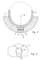
- bearing housing part 2 with a bearing element mounted thereon 4 with a support layer 5 made of steel and one on it applied sliding layer 7, which does not facing sliding partner faces.
- a holding element 6 On the side facing away from the sliding partner of the Bearing element 4, a holding element 6 is provided, which in a plane perpendicular to the radial direction 8 of Bearing element a polygonal, namely 8-angular outer contour as shown in FIGS. 2 and 3 can be seen.
- the holding element 6 engages in a round recess 10 in the bearing housing part 2 a.
- the round recess 10 has an inner diameter 12 which is slightly smaller as the perimeter 14 of the holding element 6. In this way is a play-free arrangement of the bearing element 4 on Bearing housing part 2 reached.
- the corner edges 16 dig in the inner wall 18, or it will be the corner edges 16th deformed, it being contrary to material flow Pressing in of the retaining element 6 comes.
- the recess 10 an extension 20 in Form of a gradation or chamfering, which can absorb the flow of material.
Landscapes
- Engineering & Computer Science (AREA)
- General Engineering & Computer Science (AREA)
- Mechanical Engineering (AREA)
- Mounting Of Bearings Or Others (AREA)
- Sliding-Contact Bearings (AREA)
- Springs (AREA)
Description
Es ist bereits bekannt, auf der von der Gleitschicht abgewandten Seite des Lagerelements ein Halteelement vorzusehen, das in eine Ausnehmung im Lagergehäuseteil eingreift. Hierdurch kann eine drehfeste Anordnung des Lagerelements bezüglich des Lagergehäuseteils erreicht werden. Es erweist sich aber regelmäßig als aufwendig, das Halteelement und die Ausnehmung derart zu fertigen, dass sich eine passgenaue und im Wesentlichen spielfreie Festlegung des Lagerelements ergibt.
- Figur 1
- eine Schnittansicht durch ein Lagergehäuseteil mit montiertem Lagerelement (schematisch);
- Figur 2
- eine ausschnittweise Draufsicht auf den Rücken des Lagerelements mit einem Halteelement;
- Figur 3
- eine ausschnittweise Schnittansicht des Lagerelements mit Schnittebene entsprechend den Pfeilen III-III in Figur 2;
- Figur 4
- eine ausschnittsweise Draufsicht auf das Lagergehäuseteil mit einer Ausnehmung;
- Figur 5
- eine ausschnittsweise Schnittansicht durch ein Lagergehäuseteil mit montiertem Lagerelement und erweiterter Ausnehmung.
Claims (10)
- Halbkreisförmiges Lagerelement (4), mit einer Stutzschicht (5) und einer darauf aufgebrachten Gleitschicht (7), wobei ein von einer der Gleitschicht (7) abgewandten Seite der Stützschicht (5) vorspringendes polygonales Halteelement (6) vorgesehen ist, das zur drehfesten Verankerung des Lagerelements (4) im montierten Zustand in eine entsprechend ausgebildete Ausnehmung (10) in einem Lagergehäuseteil (2) eingreift, dadurch gekennzeichnet, dass das Halteelement (6) in einer Querschnittsebene senkrecht zu einer radialen Richtung (8) des Lagerelements (4) als Durchzug mit polygonalem Außenumfang ausgebildet ist.
- Lagerelement (4) nach Anspruch 1, dadurch gekennzeichnet, dass das Halteelement (6) 5 - 9-eckig ausgebildet ist.
- Lagerelement (4) nach Anspruch 2, dadurch gekennzeichnet, dass das Halteelement (6) 6 - 9-eckig ausgebildet ist.
- Lagerelement (4) nach Anspruch 3, dadurch gekennzeichnet, dass das Halteelement (6) 8-eckig ausgebildet ist.
- Anordnung aus einem Lagerelement (4) nach einem oder mehreren der vorstehenden Ansprüche und einem Lagergehäuseteil (2) zur Aufnahme des Lagerelements (4) mit einer Ausnehmung (10), in welche das Halteelement (6) des Lagerelements (4) zur drehfesten Verankerung des Lagerelements (4) eingreift, dadurch gekennzeichnet, dass die Ausnehmung (10) in dem Lagergehäuseteil (2) in einer Querschnittsebene senkrecht zur radialen Richtung (8) des Lagerelements (4) rund ausgebildet ist und der Innendurchmesser (12) der Ausnehmung (10) kleiner ist als der Durchmesser des Umkreises (14) der Polygonform des Halteelements (6).
- Anordnung nach Anspruch 5, dadurch gekennzeichnet, dass der Innendurchmesser (14) der Ausnehmung (10) unter Berücksichtigung von Fehlertoleranzen bei der Herstellung so ausgewählt wird, dass der obere Wert für den Innendurchmesser (12) kleiner ist als der untere Wert für den Durchmesser des Umkreises (14) der Polygonform des Halteelements.
- Anordnung nach Anspruch 5 oder 6, dadurch gekennzeichnet, dass der Durchmesser des Umkreises (14) des Haltelements (6) 4 - 8 mm beträgt und der Durchmesser der Ausnehmung (10) 0,05 - 0,15 mm geringer ist.
- Anordnung nach Anspruch 5, 6 oder 7, dadurch gekennzeichnet, dass der Durchmesser des Umkreises (14) des Haltelements (6) und der Durchmesser der Ausnehmung (10) derart bemessen sind, dass sich zum Einpressen des Halteelements (6) in die Ausnehmung (10) bei der Montage des Lagerelements (4) am Lagergehäuseteil (2) eine Einpreßkraft von 310 - 2200 N ergibt.
- Anordnung nach Ansprüche 5 - 8, dadurch gekennzeichnet, dass zum Lösen des montierten Halteelements (6) vom Lagergehäuseteil (2) eine Ausziehkraft von 40 - 420 N erforderlich ist.
- Anordnung nach Ansprüche 5 - 9, dadurch gekennzeichnet, dass die Ausnehmung (10) im Bereich des Übergangs zu einer Lageraufnahmefläche eine Abstufung oder Anfasung (20) aufweist.
Applications Claiming Priority (3)
| Application Number | Priority Date | Filing Date | Title |
|---|---|---|---|
| DE10150654A DE10150654C5 (de) | 2001-10-13 | 2001-10-13 | Lagerelement |
| DE10150654 | 2001-10-13 | ||
| PCT/EP2002/008707 WO2003033927A1 (de) | 2001-10-13 | 2002-08-05 | Lagerelement |
Publications (2)
| Publication Number | Publication Date |
|---|---|
| EP1434948A1 EP1434948A1 (de) | 2004-07-07 |
| EP1434948B1 true EP1434948B1 (de) | 2005-03-09 |
Family
ID=7702442
Family Applications (1)
| Application Number | Title | Priority Date | Filing Date |
|---|---|---|---|
| EP02801283A Expired - Lifetime EP1434948B1 (de) | 2001-10-13 | 2002-08-05 | Lagerelement |
Country Status (6)
| Country | Link |
|---|---|
| US (1) | US20040240758A1 (de) |
| EP (1) | EP1434948B1 (de) |
| BR (1) | BR0213232A (de) |
| DE (2) | DE10150654C5 (de) |
| ES (1) | ES2237715T3 (de) |
| WO (1) | WO2003033927A1 (de) |
Families Citing this family (6)
| Publication number | Priority date | Publication date | Assignee | Title |
|---|---|---|---|---|
| DE10203444B4 (de) * | 2002-01-30 | 2006-07-20 | Man Nutzfahrzeuge Ag | Verdrehsicherung für Lagerschalen |
| WO2006081560A1 (en) * | 2005-01-28 | 2006-08-03 | Vrb, Llc | V-roller bearing and engine |
| DE102006055161A1 (de) * | 2006-11-22 | 2008-05-29 | Robert Bosch Gmbh | Lagerschale für eine hydrostatische Maschine und hydrostatische Maschine mit dieser Lagerschale |
| JP5472340B2 (ja) * | 2012-02-10 | 2014-04-16 | 株式会社デンソー | 燃料供給ポンプ |
| DE102013101498A1 (de) | 2013-02-14 | 2014-08-28 | Knorr-Bremse Systeme für Schienenfahrzeuge GmbH | Kurbeltriebanordnung eines vorzugsweise ölfreien Kolbenverdichters |
| DE102016012934A1 (de) * | 2016-10-27 | 2018-05-03 | Mann + Hummel Gmbh | Lagervorrichtung zum Lagern einer Welle sowie Sauganlage mit wenigstens einer solchen Lagervorrichtung |
Family Cites Families (18)
| Publication number | Priority date | Publication date | Assignee | Title |
|---|---|---|---|---|
| US239290A (en) * | 1881-03-22 | Journal-box | ||
| US35622A (en) * | 1862-06-17 | Improved bush for the sheaves of tackle-blocks | ||
| US1700100A (en) * | 1929-01-22 | Bushing | ||
| US212665A (en) * | 1879-02-25 | Improvement in journal-boxes | ||
| DE675607C (de) * | 1935-05-22 | 1939-05-12 | Gen Motors Corp | Verfahren zum Herstellen geflanschter Lagerschalen |
| US2503028A (en) * | 1948-05-19 | 1950-04-04 | American Brake Shoe Co | Bearing |
| DE1477052B1 (de) * | 1964-02-01 | 1970-06-04 | Glyco Metall Werke Dalen & Loo | Verfahren und Vorrichtung zum Anbringen von Haltenocken an vorzugsweise kalibrierten Gleitlagerschalen |
| US3433539A (en) * | 1966-12-09 | 1969-03-18 | Gen Motors Corp | Bearing retainer |
| US3672030A (en) * | 1970-03-09 | 1972-06-27 | Production Experts Inc | Downcoiler mandrel of the toggle link type for hot strip mills, and methods for repairing or rebuilding same |
| IT981409B (it) * | 1973-03-15 | 1974-10-10 | Magneti Marelli Spa | Perfezionamento alle strutture di supporto di alberi rotanti realizzate con cuscinetti porosi sinterizzati |
| US4412753A (en) * | 1981-09-03 | 1983-11-01 | Linn James F | Quick-opening bearing block |
| DE3230700C2 (de) * | 1982-08-18 | 1985-04-25 | Glyco-Metall-Werke Daelen & Loos Gmbh, 6200 Wiesbaden | Verfahren zur Herstellung eines radialen Haltevorsprungs an einer Gleitlagerschale |
| DE3403671A1 (de) * | 1984-02-03 | 1985-07-04 | Daimler-Benz Ag, 7000 Stuttgart | Gleitlagerung mit lagerschale oder anlaufscheibe |
| DE3905175C1 (en) * | 1989-02-20 | 1990-08-09 | Hans-Hermann 4817 Leopoldshoehe De Heusinger Von Waldegge | Pipe clamp for hydraulic pipes |
| DE19631663C2 (de) * | 1996-08-06 | 1998-08-06 | Glyco Metall Werke | Lagerschale mit Haltenocken und Verfahren zu seiner Herstellung |
| JP3276064B2 (ja) * | 1997-09-26 | 2002-04-22 | 大同メタル工業株式会社 | ラックピニオン式ステアリング装置のラックガイド |
| CA2287668A1 (en) * | 1998-12-28 | 2000-06-28 | William F. Hartery | Plate and bolt assembly |
| ATE274878T1 (de) * | 1999-11-03 | 2004-09-15 | Biomet Merck Gmbh | Künstliche hüftgelenkpfanne |
-
2001
- 2001-10-13 DE DE10150654A patent/DE10150654C5/de not_active Expired - Fee Related
-
2002
- 2002-08-05 WO PCT/EP2002/008707 patent/WO2003033927A1/de not_active Ceased
- 2002-08-05 US US10/489,361 patent/US20040240758A1/en not_active Abandoned
- 2002-08-05 EP EP02801283A patent/EP1434948B1/de not_active Expired - Lifetime
- 2002-08-05 DE DE50202443T patent/DE50202443D1/de not_active Expired - Lifetime
- 2002-08-05 ES ES02801283T patent/ES2237715T3/es not_active Expired - Lifetime
- 2002-08-05 BR BR0213232-0A patent/BR0213232A/pt not_active Application Discontinuation
Also Published As
| Publication number | Publication date |
|---|---|
| EP1434948A1 (de) | 2004-07-07 |
| DE10150654C1 (de) | 2003-02-20 |
| WO2003033927A1 (de) | 2003-04-24 |
| ES2237715T3 (es) | 2005-08-01 |
| DE10150654C5 (de) | 2008-07-10 |
| DE50202443D1 (de) | 2005-04-14 |
| BR0213232A (pt) | 2004-09-28 |
| US20040240758A1 (en) | 2004-12-02 |
Similar Documents
| Publication | Publication Date | Title |
|---|---|---|
| DE69409574T2 (de) | Scheibenwischer mit Gelenkverbindung zwischen Kurbel und Gelenkstange | |
| DE69927078T2 (de) | Kombiniertes Lager | |
| DE102020200947B4 (de) | Halbes drucklager für kurbelwelle eines verbrennungsmotors | |
| DE10153441B4 (de) | Halteelement zur Festlegung eines Maschinenteils | |
| DE102020200943B4 (de) | Halbes drucklager für kurbelwelle eines verbrennungsmotors | |
| WO2009135720A1 (de) | Träger mit druckausgleichsmembran sowie antriebsvorrichtung, insbesondere für kraftfahrzeuganwendungen | |
| WO2023275313A1 (de) | Flüssigkeitspumpe | |
| DE10150654C5 (de) | Lagerelement | |
| DE102008048261B4 (de) | Axialturbomaschinenrotor mit einem Schaufelschloss und Verfahren zum Herstellen desselben | |
| EP1576714B1 (de) | Antriebseinheit für Stellantriebe im Kraftfahrzeug | |
| DE3415080A1 (de) | Ventilanordnung fuer einen teleskopschwingungsdaempfer | |
| DE69412066T2 (de) | Kupplungseinheit mit ferdernder einspannung der tellerfeder und dafür bestimmte vorrichtung | |
| EP3765761B1 (de) | Scheibenbremse für nutzfahrzeuge | |
| DE102008028103A1 (de) | Verstellbeschlag | |
| DE10203444B4 (de) | Verdrehsicherung für Lagerschalen | |
| DE19836239A1 (de) | Fahrzeugrad | |
| DE19702627C1 (de) | Dämpfkolben für einen Schwingungsdämpfer | |
| DE19945652C2 (de) | Lagerkonstruktion für eine Antriebswelle | |
| EP1288088B1 (de) | Wischeranlage mit einer Platine | |
| DE102008009474A1 (de) | Getriebe-Antriebseinheit mit einer Lageranordnung | |
| DE102006018738B3 (de) | Zweischenkliger Anker für Pendeluhr | |
| EP1498218B1 (de) | Verfahren zur Herstellung eines Leichtbau-Funktionsteils und Leichtbau-Funktionsteil | |
| EP1503082A1 (de) | Seitenkanalgrundkörper für eine Seitenkanalpumpe | |
| DE102024106550A1 (de) | Lagersitz für ein Wellenlager sowie Kraftfahrzeug | |
| DE102005023412B4 (de) | Einrichtung zur Lagerung einer ringförmigen Bremsscheibe auf einer Radnabe |
Legal Events
| Date | Code | Title | Description |
|---|---|---|---|
| PUAI | Public reference made under article 153(3) epc to a published international application that has entered the european phase |
Free format text: ORIGINAL CODE: 0009012 |
|
| 17P | Request for examination filed |
Effective date: 20031220 |
|
| AK | Designated contracting states |
Kind code of ref document: A1 Designated state(s): AT BE BG CH CY CZ DE DK EE ES FI FR GB GR IE IT LI LU MC NL PT SE SK TR |
|
| AX | Request for extension of the european patent |
Extension state: AL LT LV MK RO SI |
|
| GRAP | Despatch of communication of intention to grant a patent |
Free format text: ORIGINAL CODE: EPIDOSNIGR1 |
|
| GRAS | Grant fee paid |
Free format text: ORIGINAL CODE: EPIDOSNIGR3 |
|
| GRAA | (expected) grant |
Free format text: ORIGINAL CODE: 0009210 |
|
| AK | Designated contracting states |
Kind code of ref document: B1 Designated state(s): DE ES FR GB IT SE |
|
| REG | Reference to a national code |
Ref country code: GB Ref legal event code: FG4D Free format text: NOT ENGLISH |
|
| GBT | Gb: translation of ep patent filed (gb section 77(6)(a)/1977) |
Effective date: 20050309 |
|
| REG | Reference to a national code |
Ref country code: IE Ref legal event code: FG4D Free format text: GERMAN |
|
| REF | Corresponds to: |
Ref document number: 50202443 Country of ref document: DE Date of ref document: 20050414 Kind code of ref document: P |
|
| REG | Reference to a national code |
Ref country code: SE Ref legal event code: TRGR |
|
| REG | Reference to a national code |
Ref country code: ES Ref legal event code: FG2A Ref document number: 2237715 Country of ref document: ES Kind code of ref document: T3 |
|
| PGFP | Annual fee paid to national office [announced via postgrant information from national office to epo] |
Ref country code: SE Payment date: 20050824 Year of fee payment: 4 |
|
| PGFP | Annual fee paid to national office [announced via postgrant information from national office to epo] |
Ref country code: ES Payment date: 20050829 Year of fee payment: 4 |
|
| PLBI | Opposition filed |
Free format text: ORIGINAL CODE: 0009260 |
|
| PLAX | Notice of opposition and request to file observation + time limit sent |
Free format text: ORIGINAL CODE: EPIDOSNOBS2 |
|
| 26 | Opposition filed |
Opponent name: FEDERAL-MOGUL WIESBADEN GMBH & CO. KG Effective date: 20051117 |
|
| ET | Fr: translation filed | ||
| PLBB | Reply of patent proprietor to notice(s) of opposition received |
Free format text: ORIGINAL CODE: EPIDOSNOBS3 |
|
| PG25 | Lapsed in a contracting state [announced via postgrant information from national office to epo] |
Ref country code: SE Free format text: LAPSE BECAUSE OF NON-PAYMENT OF DUE FEES Effective date: 20060806 |
|
| PGFP | Annual fee paid to national office [announced via postgrant information from national office to epo] |
Ref country code: IT Payment date: 20060831 Year of fee payment: 5 |
|
| EUG | Se: european patent has lapsed | ||
| REG | Reference to a national code |
Ref country code: ES Ref legal event code: FD2A Effective date: 20060807 |
|
| PLCK | Communication despatched that opposition was rejected |
Free format text: ORIGINAL CODE: EPIDOSNREJ1 |
|
| PG25 | Lapsed in a contracting state [announced via postgrant information from national office to epo] |
Ref country code: ES Free format text: LAPSE BECAUSE OF NON-PAYMENT OF DUE FEES Effective date: 20060807 |
|
| PLBN | Opposition rejected |
Free format text: ORIGINAL CODE: 0009273 |
|
| STAA | Information on the status of an ep patent application or granted ep patent |
Free format text: STATUS: OPPOSITION REJECTED |
|
| PLAB | Opposition data, opponent's data or that of the opponent's representative modified |
Free format text: ORIGINAL CODE: 0009299OPPO |
|
| 27O | Opposition rejected |
Effective date: 20080201 |
|
| PG25 | Lapsed in a contracting state [announced via postgrant information from national office to epo] |
Ref country code: IT Free format text: LAPSE BECAUSE OF NON-PAYMENT OF DUE FEES Effective date: 20070805 |
|
| PGFP | Annual fee paid to national office [announced via postgrant information from national office to epo] |
Ref country code: GB Payment date: 20120918 Year of fee payment: 11 |
|
| PGFP | Annual fee paid to national office [announced via postgrant information from national office to epo] |
Ref country code: FR Payment date: 20130820 Year of fee payment: 12 |
|
| GBPC | Gb: european patent ceased through non-payment of renewal fee |
Effective date: 20130805 |
|
| PG25 | Lapsed in a contracting state [announced via postgrant information from national office to epo] |
Ref country code: GB Free format text: LAPSE BECAUSE OF NON-PAYMENT OF DUE FEES Effective date: 20130805 |
|
| REG | Reference to a national code |
Ref country code: FR Ref legal event code: ST Effective date: 20150430 |
|
| PG25 | Lapsed in a contracting state [announced via postgrant information from national office to epo] |
Ref country code: FR Free format text: LAPSE BECAUSE OF NON-PAYMENT OF DUE FEES Effective date: 20140901 |
|
| PGFP | Annual fee paid to national office [announced via postgrant information from national office to epo] |
Ref country code: DE Payment date: 20171024 Year of fee payment: 16 |
|
| REG | Reference to a national code |
Ref country code: DE Ref legal event code: R119 Ref document number: 50202443 Country of ref document: DE |
|
| PG25 | Lapsed in a contracting state [announced via postgrant information from national office to epo] |
Ref country code: DE Free format text: LAPSE BECAUSE OF NON-PAYMENT OF DUE FEES Effective date: 20190301 |