EP1434293A2 - Bipolarplatte und Verfahren zu ihrer Herstellung - Google Patents
Bipolarplatte und Verfahren zu ihrer Herstellung Download PDFInfo
- Publication number
- EP1434293A2 EP1434293A2 EP03029485A EP03029485A EP1434293A2 EP 1434293 A2 EP1434293 A2 EP 1434293A2 EP 03029485 A EP03029485 A EP 03029485A EP 03029485 A EP03029485 A EP 03029485A EP 1434293 A2 EP1434293 A2 EP 1434293A2
- Authority
- EP
- European Patent Office
- Prior art keywords
- bipolar plate
- conductive material
- tissue
- electrically non
- fabric
- Prior art date
- Legal status (The legal status is an assumption and is not a legal conclusion. Google has not performed a legal analysis and makes no representation as to the accuracy of the status listed.)
- Withdrawn
Links
Images


Classifications
-
- H—ELECTRICITY
- H01—ELECTRIC ELEMENTS
- H01M—PROCESSES OR MEANS, e.g. BATTERIES, FOR THE DIRECT CONVERSION OF CHEMICAL ENERGY INTO ELECTRICAL ENERGY
- H01M8/00—Fuel cells; Manufacture thereof
- H01M8/02—Details
- H01M8/0202—Collectors; Separators, e.g. bipolar separators; Interconnectors
- H01M8/0204—Non-porous and characterised by the material
- H01M8/0223—Composites
- H01M8/0228—Composites in the form of layered or coated products
-
- H—ELECTRICITY
- H01—ELECTRIC ELEMENTS
- H01M—PROCESSES OR MEANS, e.g. BATTERIES, FOR THE DIRECT CONVERSION OF CHEMICAL ENERGY INTO ELECTRICAL ENERGY
- H01M8/00—Fuel cells; Manufacture thereof
- H01M8/02—Details
- H01M8/0202—Collectors; Separators, e.g. bipolar separators; Interconnectors
- H01M8/0204—Non-porous and characterised by the material
- H01M8/0206—Metals or alloys
-
- H—ELECTRICITY
- H01—ELECTRIC ELEMENTS
- H01M—PROCESSES OR MEANS, e.g. BATTERIES, FOR THE DIRECT CONVERSION OF CHEMICAL ENERGY INTO ELECTRICAL ENERGY
- H01M8/00—Fuel cells; Manufacture thereof
- H01M8/02—Details
- H01M8/0202—Collectors; Separators, e.g. bipolar separators; Interconnectors
- H01M8/0204—Non-porous and characterised by the material
- H01M8/0221—Organic resins; Organic polymers
-
- H—ELECTRICITY
- H01—ELECTRIC ELEMENTS
- H01M—PROCESSES OR MEANS, e.g. BATTERIES, FOR THE DIRECT CONVERSION OF CHEMICAL ENERGY INTO ELECTRICAL ENERGY
- H01M8/00—Fuel cells; Manufacture thereof
- H01M8/02—Details
- H01M8/0202—Collectors; Separators, e.g. bipolar separators; Interconnectors
- H01M8/0247—Collectors; Separators, e.g. bipolar separators; Interconnectors characterised by the form
- H01M8/0256—Vias, i.e. connectors passing through the separator material
-
- H—ELECTRICITY
- H01—ELECTRIC ELEMENTS
- H01M—PROCESSES OR MEANS, e.g. BATTERIES, FOR THE DIRECT CONVERSION OF CHEMICAL ENERGY INTO ELECTRICAL ENERGY
- H01M8/00—Fuel cells; Manufacture thereof
- H01M8/02—Details
- H01M8/0202—Collectors; Separators, e.g. bipolar separators; Interconnectors
- H01M8/0258—Collectors; Separators, e.g. bipolar separators; Interconnectors characterised by the configuration of channels, e.g. by the flow field of the reactant or coolant
-
- H—ELECTRICITY
- H01—ELECTRIC ELEMENTS
- H01M—PROCESSES OR MEANS, e.g. BATTERIES, FOR THE DIRECT CONVERSION OF CHEMICAL ENERGY INTO ELECTRICAL ENERGY
- H01M8/00—Fuel cells; Manufacture thereof
- H01M8/02—Details
- H01M8/0202—Collectors; Separators, e.g. bipolar separators; Interconnectors
- H01M8/0267—Collectors; Separators, e.g. bipolar separators; Interconnectors having heating or cooling means, e.g. heaters or coolant flow channels
-
- H—ELECTRICITY
- H01—ELECTRIC ELEMENTS
- H01M—PROCESSES OR MEANS, e.g. BATTERIES, FOR THE DIRECT CONVERSION OF CHEMICAL ENERGY INTO ELECTRICAL ENERGY
- H01M8/00—Fuel cells; Manufacture thereof
- H01M8/02—Details
- H01M8/0271—Sealing or supporting means around electrodes, matrices or membranes
- H01M8/0273—Sealing or supporting means around electrodes, matrices or membranes with sealing or supporting means in the form of a frame
-
- H—ELECTRICITY
- H01—ELECTRIC ELEMENTS
- H01M—PROCESSES OR MEANS, e.g. BATTERIES, FOR THE DIRECT CONVERSION OF CHEMICAL ENERGY INTO ELECTRICAL ENERGY
- H01M8/00—Fuel cells; Manufacture thereof
- H01M8/24—Grouping of fuel cells, e.g. stacking of fuel cells
- H01M8/2465—Details of groupings of fuel cells
- H01M8/2483—Details of groupings of fuel cells characterised by internal manifolds
-
- Y—GENERAL TAGGING OF NEW TECHNOLOGICAL DEVELOPMENTS; GENERAL TAGGING OF CROSS-SECTIONAL TECHNOLOGIES SPANNING OVER SEVERAL SECTIONS OF THE IPC; TECHNICAL SUBJECTS COVERED BY FORMER USPC CROSS-REFERENCE ART COLLECTIONS [XRACs] AND DIGESTS
- Y02—TECHNOLOGIES OR APPLICATIONS FOR MITIGATION OR ADAPTATION AGAINST CLIMATE CHANGE
- Y02E—REDUCTION OF GREENHOUSE GAS [GHG] EMISSIONS, RELATED TO ENERGY GENERATION, TRANSMISSION OR DISTRIBUTION
- Y02E60/00—Enabling technologies; Technologies with a potential or indirect contribution to GHG emissions mitigation
- Y02E60/30—Hydrogen technology
- Y02E60/50—Fuel cells
-
- Y—GENERAL TAGGING OF NEW TECHNOLOGICAL DEVELOPMENTS; GENERAL TAGGING OF CROSS-SECTIONAL TECHNOLOGIES SPANNING OVER SEVERAL SECTIONS OF THE IPC; TECHNICAL SUBJECTS COVERED BY FORMER USPC CROSS-REFERENCE ART COLLECTIONS [XRACs] AND DIGESTS
- Y02—TECHNOLOGIES OR APPLICATIONS FOR MITIGATION OR ADAPTATION AGAINST CLIMATE CHANGE
- Y02P—CLIMATE CHANGE MITIGATION TECHNOLOGIES IN THE PRODUCTION OR PROCESSING OF GOODS
- Y02P70/00—Climate change mitigation technologies in the production process for final industrial or consumer products
- Y02P70/50—Manufacturing or production processes characterised by the final manufactured product
Definitions
- the present invention relates to a bipolar plate for fuel cell stacks and a Process for the production of the bipolar plate.
- Fuel cells are energy converters convert the chemical energy into electrical energy. In the fuel cell it will Principle of electrolysis reversed.
- a single PEM fuel cell has a symmetrical structure.
- a catalyst layer and gas distribution layer follow on both sides, to which a bipolar plate follows.
- Current collectors are used to tap the electrical Tension, while end plates metering the reaction gases and exhausting ensure the reaction products.
- bipolar plates Three different types are currently used. For one thing metallic bipolar plates used, for example made of stainless steel or coated other materials, such as aluminum or titanium.
- Metallic materials are characterized by high gas tightness, dimensional accuracy and high electrical conductivity.
- Graphitic bipolar plates can be brought into the appropriate shape by pressing or milling become. They are characterized by chemical resistance and low contact resistance from, but in addition to a high weight have an insufficient mechanical Behavior.
- Composite materials are made of special plastics that contain conductive fillers, about based on carbon.
- WO 98/33224 describes bipolar plates made of iron alloys, which have high proportions have chromium and nickel.
- bipolar plates made of plastic material which by electrical conductive fillers such as carbon powder are made conductive.
- electrical conductive fillers such as carbon powder are made conductive.
- there is a superficial metal coating over the edges of the bipolar plate enables an electrically conductive connection between two cells.
- a polymer resin is made by introducing an electrically conductive Powder and a hydrophilizing agent treated. With silica particles and graphite powder filled polymer masses are used as bipolar plates. Find in particular phenolic resins application.
- Bipolar plates made of electrically non-conductive materials for example thermoplastic Bipolar plates are made conductive in the prior art by various methods.
- an electrically conductive filler such as carbon powder, carbon fiber or metal particles, for example powder or chips of titanium, aluminum, stainless steel, silver, gold, etc.
- the disadvantage here is that the modification, for example, of a polymer with a conductive Filler a deterioration in the material properties of the polymer (for example Pourability, mechanical properties).
- bipolar plates are critical functional elements of fuel cell stacks, that too contribute significantly to the cost and weight of the stacks great demand for bipolar plates that meet the above requirement profile meet and avoid the disadvantages of the known bipolar plates. In particular, should an uncomplicated and inexpensive production of bipolar plates may be possible.
- the present invention furthermore relates to a bipolar plate for fuel cell stacks with a surrounding frame made of an electrically non-conductive material and an inner bipolar plate region enclosed by the frame from the non-conductive material that has channels for gases and possibly for coolants and that of a large proportion of the volume is essentially in two dimensions extending electrically conductive fabric is covered on both sides, the Tissue with a smaller proportion of its volume for through-plating in the electrically non-conductive material of the inner bipolar plate area is included.
- a fuel cell stack is a stack of at least one to understand two individual cells each separated by the bipolar plates.
- Fuel cell stacks are created by repeatedly stacking the bipolar plate, Gas distribution layer, catalyst layer, polymer membrane, catalyst layer and gas distribution layer manufactured.
- a stack has an electrically conductive one Electrode plate instead of a bipolar plate.
- the bipolar plate according to the invention has a peripheral frame and one of the Frame enclosed inner bipolar plate area made of an electrically non-conductive Material on. This construction of the bipolar plate creates a separation of functions performed.
- the frame serves to design the feed and discharge channels contained therein for gases and coolants.
- those combined with membrane electrode units can be used bipolar plates according to the invention via the bipolar plate frame with one another pressed and fastened in a housing without additional insulation, whereby in advantageously no leakage currents and short circuits between the bipolar plates occur.
- the inner bipolar plate area provides the electrically conductive tissue for the electrical conductivity of the bipolar plate according to the invention. It also contains its surface channels for gases, the so-called "flow field", which is the gaseous Reactants (e.g. hydrogen and oxygen) over the anode or cathode surface distributed.
- the inner bipolar plate area further contains channels for coolant in its interior.
- the individual cells of a stack have to be cooled with increasing power density. In many cases, air cooling is sufficient due to the limited heat transfer not from. A liquid cooling with a comparable to the internal combustion engine The cooling circuit is therefore necessary. Therefore, the cooling is directly on the active Cell area (inner bipolar plate area) or locally at the via locations made so that optimal heat dissipation is realized.
- Gases and liquids are preferably channeled to the inner bipolar plate area fed into the frame of the bipolar plate and via further channels in the frame dissipated again.
- step A) of the method according to the invention a tool for producing the Bipolar plate inserted an electrically conductive tissue so that it is perpendicular to the one to be manufactured Bipolar plate is aligned and protrudes on both sides.
- fabrics are to be understood as wire or thread webs Wires or threads of electrically conductive material intertwined into stitches, knotted or connected to one another by another method known in the prior art are. Several layers of these wire or thread webs can also be stacked on top of one another and be connected.
- step B) an electrically non-conductive material for producing the Frame and the inner bipolar plate area introduced into the tool.
- the whole Bipolar plate is consequently essentially made in one piece from the electrically non-conductive Formed material, the inner bipolar plate area using the fabric electrically is made conductive.
- step B) of the invention The frame and inner bipolar plate area are perpendicular to the tissue aligned, with the tissue reaching through the inner bipolar plate region and protrudes from it on both sides.
- the fabric is bent on both sides in step D), so that it is on both sides electrically non-conductive material in the inner bipolar plate area. So in On the one hand, an advantageous electrical through-connection of the non-conductive inner Bipolar plate area reached because the tissue through this from the anode to the cathode side passes through, and on the other hand, along the entire surface of the Bipolar plate area over the electrons released in the fuel cell reaction over derived the electrically conductive tissue.
- the fabric is in a polymer electrolyte membrane (PEM) fuel cell stack a support function for the polymer electrolyte membrane takes over.
- the membrane can have pressure differences between be exposed to both of their surfaces, making them one-sided in the prior art the channels formed in the inner bipolar plate area (the flow field) and can be damaged.
- the electrically conductive fabric in the invention Bipolar plate supports the polymer electrolyte membrane, making a thinner membrane than can be used in the prior art, or the membrane also higher Withstands pressure differences.
- the tissue is after the bending in step D) of the method according to the invention at least partially on inner bipolar plate area made of non-conductive material attached. So can the fabric for example along the outer edge of the inner bipolar plate region by a thermal process, for example hot rivets, are fixed. This will make it stable Attachment of the tissue to the bipolar plate is guaranteed.
- the non-conductive material around a thermoplastic or a thermoset is preferably a polymer from the group of polyphenylene sulfide (PPS), Liquid Cristal Polyester (LCP), Polyoxymethylene (POM), Polyaryletherketone (PAEK), polyamide (PA), polybutylene terephthalate (PBT), polyphenylene oxide (PPO), Polypropylene (PP) or polyethersulfone (PES).
- PPS polyphenylene sulfide
- LCP Liquid Cristal Polyester
- POM Polyoxymethylene
- PAEK Polyaryletherketone
- PA polyamide
- PBT polybutylene terephthalate
- PPO polyphenylene oxide
- PES polyethersulfone
- the injection molding is a process in which, in a single step, finished molded parts with complex Geometry can be made. Since little or no rework is necessary, and the production of injection molded parts in short cycle times is possible injection molding around a pronounced mass production process.
- the method is used, for example, in one of the polymer materials mentioned above cast a mold in which there is already a metal mesh perpendicular to the casting direction. If the polymer material is poured directly through the metallic fabric, this creates a gas-tight polymer wall that extends through the fabric.
- An advantage of the method according to the invention is consequently that it is inexpensive to manufacture the bipolar plate, for example in injection molding and made of a bulk material becomes. Furthermore, the positive properties of the non-conductive material (for example a polymer) with those of the electrically conductive fabric (for example a metal wire mesh) combined. Due to the uniform use of the electrical non-conductive material for the frame and the inner bipolar plate area can the bipolar plate in one piece and mainly inexpensive in one step be shaped. Then only the bending of the tissue is required to to complete the bipolar plate. Furthermore, it is through the use of the non-conductive Material for the production of frames and inner bipolar plate area possible, almost to produce any geometries (for example channels for gases and coolants in the Frame and in the inner bipolar plate area).
- the injection molding of plastic material allows a spatial design of even complex geometric structures.
- the flow field can be used for even gas distribution on the surface of the inner bipolar plate area contain meandering channels.
- the electrically conductive fabric can be easily plated through with a high electrical conductivity can be achieved.
- the electrically conductive fabric is in a preferred embodiment of the present Invention a wire mesh made of at least one material from the group nickel (pure), nickel alloys and high-alloy steel.
- the main alloying elements for Steel is Al, B, Bi, Co, Cr, Cu, La, Mn, Mo, Ni, Pb, Se, Si, Te, V, W and Zr.
- the inner bipolar plate region is made of non-conductive material of a large proportion of the volume of one essentially covered in two dimensions, electrically conductive fabric, covered on both sides, the tissue with a smaller proportion of its volume for through-plating contained in the electrically non-conductive material of the inner bipolar plate area is.
- the portion of the fabric covering the non-conductive material is used the conduction of electrons that are released in the fuel cell reaction.
- the one in the Non-conductive material contained portion of the tissue passes through and thus ensures through-plating from one side to the other of the bipolar plate.
- the large portion of the tissue is the inner bipolar plate area covered on both sides, with the smaller proportion of the tissue that is in the non-conductive Material of the inner bipolar plate area is contained, connected via bending edges.
- the bipolar plate according to the invention is preferably according to the invention Process manufactured.
- the bipolar plates according to the invention can be used, for example, in fuel cell stacks be used for power supply in mobile and stationary facilities.
- a house supply comes in particular the power supply of vehicles such as land, water and aircraft as well as self-sufficient systems such as satellites, measuring stations or signaling devices into consideration.
- the electrically non-conductive material does not already suffice for the Shaping the frame and the inner bipolar plate area through the tissue, but the tissue is then in at least one gap in the inner bipolar plate area inserted and then the gap is filled gas-tight with a material.
- the frame and inner bipolar plate area are preferably injection molded shaped.
- the at least one gap can then already be contained in the injection molded part or subsequently e.g. be machined into it.
- the one to fill up material used can e.g. an adhesive known in the prior art or be the electrically non-conductive material from which the frame and the inner bipolar plate area are shaped.
- Figure 1 shows an embodiment of a bipolar plate according to the invention, according to the method according to the invention is produced.
- the bipolar plate 1 comprises a peripheral frame 2 and an inner bipolar plate area 3 made of an electrically non-conductive material, preferably one of the above mentioned polymer materials.
- the frame 2 and the inner bipolar plate area 3 are preferably in one piece and in one operation by an injection molding process molded of the non-conductive material.
- the frame 2 has channels for supplying and removing liquids and gases.
- H 2 can be supplied via a first input 4, for example.
- the hydrogen is then distributed in the fuel cell mode on the anode side via the channels 5 (flow field) on the surface of the inner bipolar plate region 3.
- the hydrogen not used for the fuel cell reaction is discharged again via the first outlet 6.
- the frame 2 (not shown) contains further channels for a coolant which flows through the interior of the inner bipolar plate region 3.
- openings 2 are contained in the frame 2, which are provided for mounting the bipolar plate 1 in the fuel cell stack.
- FIG. 1 In the preferred embodiment of the present invention shown in FIG. 1 is an electrically conductive fabric 10 in one piece at the edge of the inner bipolar plate area 3 inserted.
- the fabric 10 penetrates the electrically non-conductive Material at the edge of the inner bipolar plate area 3 and protrudes perpendicularly on both Pages beyond this.
- the area of each protruding on one side of the bipolar plate 1 Tissue essentially corresponds to the surface of the inner bipolar plate area 3 made of electrically non-conductive material on this page.
- the tissue it is preferably a wire mesh made of nickel, nickel alloys or alloy steel. Wire thickness, mesh size and fabric shape depend on the electrical power to be transmitted.
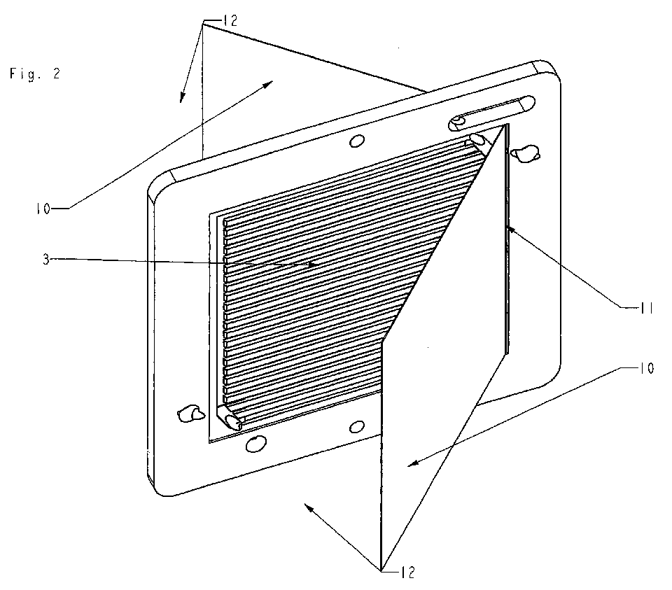
- Figure 2 shows the bending of the fabric on both sides.
- step D) of the method according to the invention is intended to illustrate step D) of the method according to the invention.
- FIG. 3 shows the finished bipolar plate according to the invention according to FIG. 1.
- the fabric 10 (as shown in Figure 2) is bent along the bending edge 11 it is in the finished bipolar plate 1 in the inner bipolar plate area 3 close to the electrically non-conductive material and completely covers it. Possibly after bending, the tissue 10 is still on the inner bipolar plate region 3 (for example on the edges 13) or also attached to the frame 2 so that it is firmly attached to the bipolar plate before the fuel cell stack is installed is.
- FIG. 4 schematically shows a further embodiment of a bipolar plate according to the invention, which is produced by the method according to the invention.
- the Completed bipolar plate 1 consequently contains a plated-through hole in the four areas, in which the four pieces of fabric 14, 15, 16, 17 by the electrically non-conductive Pass the material through.
- FIG. 5 schematically shows a further embodiment of a bipolar plate according to the invention, which is produced by the method according to the invention.
- the bipolar plate 1 also contains the inner one Bipolar plate area 3, the electrically conductive tissue 10 in several pieces 14, 15, 16, 17.
- the four square pieces of fabric 14, 15, 16, 17 cut the inner one Bipolar plate region 3 each along one of its edges delimited by the frame 2.
- the fabric pieces 14, 15, 16, 17 penetrate the electrically non-conductive material in the area of their one diagonal, so that triangular pieces of fabric over the inner Project bipolar plate area 3 vertically.
- These triangular pieces of tissue will be each along a bending edge 18, 19, 20, 21 towards the center of the inner bipolar plate region 3 bent over to complete the bipolar plate 1 according to the invention.
- the sum of the triangular areas corresponds to the entire surface of the inner one Bipolar plate region 3, so that it is completely covered by tissue 10 after the bending is covered.
- the through-contacting of the bipolar plate 1 lies in the edge region in this embodiment of the inner bipolar plate region 3.
Landscapes
- Chemical & Material Sciences (AREA)
- Life Sciences & Earth Sciences (AREA)
- Engineering & Computer Science (AREA)
- Manufacturing & Machinery (AREA)
- Sustainable Development (AREA)
- Sustainable Energy (AREA)
- Chemical Kinetics & Catalysis (AREA)
- Electrochemistry (AREA)
- General Chemical & Material Sciences (AREA)
- Composite Materials (AREA)
- Fuel Cell (AREA)
Abstract
Description
- chemische Beständigkeit gegen feuchte oxidierende und reduzierende Bedingungen
- Gasdichtheit
- hohe Leitfähigkeit
- geringe Übergangswiderstände
- Maßhaltigkeit
- niedrige Kosten in bezug auf Material und Fertigung
- Gestaltungsfreiheit
- hohe mechanische Belastbarkeit
- Korrosionsbeständigkeit
- geringes Gewicht.
- Figur 1
- eine Ausführungsform einer erfindungsgemäßen Bipolarplatte, die nach dem erfindungsgemäßen Verfahren hergestellt wird,
- Figur 2
- das beidseitige Umbiegen des Gewebes,
- Figur 3
- die fertiggestellte erfindungsgemäße Bipolarplatte gemäß Figur 1,
- Figur 4
- eine weitere Ausführungsform einer erfindungsgemäßen Bipolarplatte, die nach dem erfindungsgemäßen Verfahren hergestellt wird und bei der das Gewebe in mehreren Stücken an verschiedenen Stellen des inneren Bipolarplattenbereichs eingelegt ist und
- Figur 5
- eine weitere Ausführungsform einer erfindungsgemäßen Bipolarplatte, die nach dem erfindungsgemäßen Verfahren hergestellt wird.
- 1
- Bipolarplatte
- 2
- Rahmen
- 3
- innerer Bipolarplattenbereich
- 4
- erster Eingang (H2)
- 5
- Kanäle
- 6
- erster Ausgang (H2)
- 7
- zweiter Eingang (O2)
- 8
- zweiter Ausgang (O2)
- 9
- Öffnungen
- 10
- elektrisch leitfähiges Gewebe
- 11
- Biegekante
- 12
- Biegerichtung
- 13
- Ränder
- 14
- erstes viereckiges Gewebestück
- 15
- zweites viereckiges Gewebestück
- 16
- drittes viereckiges Gewebestück
- 17
- viertes viereckiges Gewebestück
- 18
- erste Biegekante
- 19
- zweite Biegekante
- 20
- dritte Biegekante
- 21
- vierte Biegekante
Claims (11)
- Verfahren zur Herstellung einer Bipolarplatte (1) für Brennstoffzellen-Stacks, wobei die Bipolarplatte (1) einen umlaufenden Rahmen (2) aus einem elektrisch nichtleitenden Werkstoff und einen von dem Rahmen (2) umschlossenen inneren Bipolarplattenbereich (3) aus dem elektrisch nichtleitenden Werkstoff mit Kanälen (5) für Gase und gegebenenfalls für Kühlmittel aufweist, mit folgenden Verfahrensschritten:A) Einlegen eines sich im Wesentlichen in zwei Dimensionen erstreckenden elektrisch leitfähigen Gewebes (10) in ein Werkzeug zur Herstellung der Bipolarplatte (1), wobei das Gewebe (10) im Wesentlichen senkrecht zu der Ausrichtung der herzustellenden Bipolarplatte (1) eingelegt wird und beidseitig über die herzustellende Bipolarplatte (1) hinausragt,B) Einbringen des elektrisch nichtleitenden Werkstoffes in das Werkzeug zum Formen des Rahmens (2) und des inneren Bipolarplattenbereichs (3), wobei der elektrisch nichtleitende Werkstoff durch das Gewebe (10) hindurchreicht,C) Entnehmen der geformten Bipolarplatte (1) aus dem Werkzeug undD) beidseitiges Umbiegen des über den inneren Bipolarplattenbereich (3) hinausragenden Gewebes (10), so dass es den inneren Bipolarplattenbereich (3) aus dem nichtleitenden Werkstoff bedeckt.
- Verfahren zur Herstellung einer Bipolarplatte (1) für Brennstoffzellen-Stacks, wobei die Bipolarplatte (1) einen umlaufenden Rahmen (2) aus einem elektrisch nichtleitenden Werkstoff und einen von dem Rahmen (2) umschlossenen inneren Bipolarplattenbereich (3) aus dem elektrisch nichtleitenden Werkstoff mit Kanälen (5) für Gase und gegebenenfalls für Kühlmittel aufweist, mit folgenden Verfahrensschritten:i) Formen des Rahmens (2) und des inneren Bipolarplattenbereichs (3) aus dem elektrisch nichtleitenden Werkstoff, wobei in den inneren Bipolarplattenbereich (3) mindestens ein Spalt eingebracht wird,ii) Einlegen eines sich im Wesentlichen in zwei Dimensionen erstreckenden elektrisch leitfähigen Gewebes (10) in den mindestens einen Spalt, so dass das Gewebe (10) im Wesentlichen senkrecht zu der Ausrichtung der herzustellenden Bipolarplatte (1) eingelegt wird und beidseitig über die herzustellende Bipolarplatte (1) hinausragt,iii) beidseitiges Umbiegen des über den inneren Bipolarplattenbereich (3) hinausragenden Gewebes (10), so dass es den inneren Bipolarplattenbereich (3) aus dem nichtleitenden Werkstoff bedeckt,iv) Schließen des mindestens einen Spaltes unter Einbindung des durch den Spalt hindurchreichenden Gewebes (10) durch gasdichtes Auffüllen mit einem Werkstoff.
- Verfahren gemäß einem der Ansprüche 1 oder 2, dadurch gekennzeichnet, dass das Gewebe (10) nach dem Umbiegen in Schritt D) bzw. in Schritt iii) zumindest teilweise am inneren Bipolarplattenbereich (3) aus nichtleitendem Werkstoff befestigt wird.
- Verfahren gemäß einem der Ansprüche 1 bis 3, dadurch gekennzeichnet, dass der elektrisch nichtleitende Werkstoff in Schritt B) bzw. in Schritt i) mittels Spritzgießen in das Werkzeug eingebracht bzw. geformt wird.
- Verfahren gemäß einem der Ansprüche 1 bis 4, dadurch gekennzeichnet, dass der nichtleitende Werkstoff ein Thermoplast oder ein Duroplast ist.
- Verfahren gemäß einem der Ansprüche 1 bis 5, dadurch gekennzeichnet, dass der nichtleitende Werkstoff ein Polymer aus der Gruppe PPS, LCP, POM, PAEK, PA, PBT, PPO, PP oder PES ist.
- Verfahren gemäß einem der Ansprüche 1 bis 6, dadurch gekennzeichnet, dass das Gewebe (10) ein Drahtgeflecht aus mindestens einem Werkstoff aus der Gruppe Nickel, Nickellegierungen oder hochlegierter Stahl ist.
- Verfahren gemäß einem der Ansprüche 1 bis 7, dadurch gekennzeichnet, dass das Gewebe (10) in Schritt B) bzw. in Schritt ii) in einem Stück am Rand des inneren Bipolarplattenbereichs (3) eingelegt wird.
- Verfahren gemäß einem der Ansprüche 1 bis 7, dadurch gekennzeichnet, dass das Gewebe (10) in Schritt B) bzw. in Schritt ii) in mehreren Stücken an verschiedenen Stellen des inneren Bipolarplattenbereichs (3) eingelegt wird.
- Bipolarplatte (1) für Brennstoffzellen-Stacks mit einem umlaufenden Rahmen (2) aus einem elektrisch nichtleitenden Werkstoff und einem von dem Rahmen (2) umschlossenen inneren Bipolarplattenbereich (3) aus dem nichtleitenden Werkstoff, der Kanäle (5) für Gase und gegebenenfalls für Kühlmittel aufweist und der von einem großen Anteil des Volumens eines sich im Wesentlichen in zwei Dimensionen erstreckenden elektrisch leitenden Gewebes (10) beidseitig überdeckt ist, wobei das Gewebe (10) mit einem geringeren Anteil seines Volumens zur Durchkontaktierung in dem elektrisch nichtleitenden Werkstoff des inneren Bipolarplattenbereichs (3) enthalten ist.
- Bipolarplatte gemäß Anspruch 10, dadurch gekennzeichnet, dass der große Anteil des Gewebes (10), der den inneren Bipolarplattenbereich (3) beidseitig überdeckt mit dem geringeren Anteil des Gewebes (10), der in dem elektrisch nichtleitenden Werkstoff des inneren Bipolarplattenbereichs (3) enthalten ist, über Biegekanten verbunden ist.
Applications Claiming Priority (2)
| Application Number | Priority Date | Filing Date | Title |
|---|---|---|---|
| DE10261483 | 2002-12-23 | ||
| DE10261483A DE10261483A1 (de) | 2002-12-23 | 2002-12-23 | Bipolarplatte und Verfahren zu ihrer Herstellung |
Publications (2)
| Publication Number | Publication Date |
|---|---|
| EP1434293A2 true EP1434293A2 (de) | 2004-06-30 |
| EP1434293A3 EP1434293A3 (de) | 2011-08-24 |
Family
ID=32404346
Family Applications (1)
| Application Number | Title | Priority Date | Filing Date |
|---|---|---|---|
| EP03029485A Withdrawn EP1434293A3 (de) | 2002-12-23 | 2003-12-19 | Bipolarplatte und Verfahren zu ihrer Herstellung |
Country Status (3)
| Country | Link |
|---|---|
| US (1) | US7150846B2 (de) |
| EP (1) | EP1434293A3 (de) |
| DE (1) | DE10261483A1 (de) |
Cited By (2)
| Publication number | Priority date | Publication date | Assignee | Title |
|---|---|---|---|---|
| WO2006125775A1 (de) * | 2005-05-27 | 2006-11-30 | Basf Aktiengesellschaft | Bipolarplatte für brennstoffzellen |
| WO2014202320A1 (de) * | 2013-06-20 | 2014-12-24 | Cellstrom Gmbh | Laminierte bipolare platte |
Families Citing this family (9)
| Publication number | Priority date | Publication date | Assignee | Title |
|---|---|---|---|---|
| US20060088760A1 (en) * | 2004-10-26 | 2006-04-27 | Hsai-Yin Lee | Metallization of composite plate for fuel cells |
| KR100696681B1 (ko) * | 2005-07-05 | 2007-03-19 | 삼성에스디아이 주식회사 | 스택 및 이를 포함하는 연료 전지 장치 |
| DK176957B1 (da) * | 2007-07-18 | 2010-07-26 | Serenergy As | Forbedringer i pakninger og bipolære plader til PEM brændselsceller |
| TWI408843B (zh) * | 2009-12-24 | 2013-09-11 | Ind Tech Res Inst | 燃料電池流場板及其形成方法 |
| US8470489B2 (en) | 2010-05-13 | 2013-06-25 | Energyor Technologies Inc. | Method for producing bipolar plates |
| TWI449250B (zh) * | 2011-04-15 | 2014-08-11 | Univ Nat Central | Composite bipolar plate |
| DE102020006654A1 (de) | 2020-10-30 | 2022-05-05 | TEWISS-Technik und Wissen GmbH | Bipolarplattenverbindung und Herstellungsverfahren |
| DE102023110388B4 (de) * | 2023-04-24 | 2026-04-02 | Schaeffler Technologies AG & Co. KG | Verfahren zur Herstellung einer Bipolarplatte |
| CN119465195A (zh) * | 2023-08-11 | 2025-02-18 | 中国科学院大连化学物理研究所 | 一种新型电解槽 |
Family Cites Families (10)
| Publication number | Priority date | Publication date | Assignee | Title |
|---|---|---|---|---|
| US4900643A (en) * | 1988-04-08 | 1990-02-13 | Globe-Union Inc. | Lead acid bipolar battery plate and method of making the same |
| US5300001A (en) * | 1993-05-03 | 1994-04-05 | Sealy Anthony J | Portable dumbbell apparatus |
| JPH09134732A (ja) * | 1995-11-10 | 1997-05-20 | Tanaka Kikinzoku Kogyo Kk | 薄型導電性ガス不透過基板、その製造方法、燃料電池用スタック構成部材及び燃料電池用スタック |
| US6300001B1 (en) | 1997-01-22 | 2001-10-09 | Siemens Aktiengesellschaft | Fuel cell and use of iron-based alloys for the construction of fuel cells |
| US5942347A (en) | 1997-05-20 | 1999-08-24 | Institute Of Gas Technology | Proton exchange membrane fuel cell separator plate |
| DE19823880A1 (de) | 1997-06-03 | 1998-12-10 | Motorola Inc | Bipolarplatte für Brennstoffzellenanordnung |
| US6071635A (en) * | 1998-04-03 | 2000-06-06 | Plug Power, L.L.C. | Easily-formable fuel cell assembly fluid flow plate having conductivity and increased non-conductive material |
| US6255012B1 (en) * | 1999-11-19 | 2001-07-03 | The Regents Of The University Of California | Pleated metal bipolar assembly |
| FR2810795B1 (fr) * | 2000-06-27 | 2002-10-04 | Technicatome | Plaque bipolaire a deux plaques metalliques pour pile a combustible et son procede de fabrication |
| US20040053104A1 (en) * | 2002-09-12 | 2004-03-18 | Novkov Donald James | Current feeders for electrochemical cell stacks |
-
2002
- 2002-12-23 DE DE10261483A patent/DE10261483A1/de not_active Withdrawn
-
2003
- 2003-12-19 EP EP03029485A patent/EP1434293A3/de not_active Withdrawn
- 2003-12-22 US US10/740,757 patent/US7150846B2/en not_active Expired - Fee Related
Cited By (2)
| Publication number | Priority date | Publication date | Assignee | Title |
|---|---|---|---|---|
| WO2006125775A1 (de) * | 2005-05-27 | 2006-11-30 | Basf Aktiengesellschaft | Bipolarplatte für brennstoffzellen |
| WO2014202320A1 (de) * | 2013-06-20 | 2014-12-24 | Cellstrom Gmbh | Laminierte bipolare platte |
Also Published As
| Publication number | Publication date |
|---|---|
| DE10261483A1 (de) | 2004-07-01 |
| EP1434293A3 (de) | 2011-08-24 |
| US7150846B2 (en) | 2006-12-19 |
| US20040131914A1 (en) | 2004-07-08 |
Similar Documents
| Publication | Publication Date | Title |
|---|---|---|
| EP1437780A2 (de) | Brennstoffzellenmodul mit umrahmter Bipolarplatte | |
| DE10039674A1 (de) | Bipolarplatte für PEM-Brennstoffzellen | |
| EP0795205B1 (de) | Brennstoffzellen und daraus hergestellte batterien | |
| DE102011085069B4 (de) | Metallischer poröser Körper für eine Brennstoffzelle | |
| DE102011088105B4 (de) | Endplatte für eine brennstoffzelle mit einem sandwich-einlegeteil | |
| DE102010045037A1 (de) | Battery array with reliable low-resistance connections | |
| DE10392176T5 (de) | Separatorplatte für eine PEM-Brennstoffzelle | |
| DE112005000978T5 (de) | Hybridbipolarplattenanordnung und Vorrichtungen, die diese enthalten | |
| DE10392548T5 (de) | Kühlmittel-Strömungsfeldkonstruktion für Brennstoffzellenstapel | |
| DE112008000024T5 (de) | Polymerelektrolyt-Brennstoffzelle | |
| DE102014210358A1 (de) | Brennstoffzellenstapel mit einer dummyzelle | |
| DE10243592A1 (de) | Bipolarplatte für PEM-Brennstoffzellen | |
| DE202009012647U1 (de) | Batteriezellenverbinder | |
| EP1434293A2 (de) | Bipolarplatte und Verfahren zu ihrer Herstellung | |
| DE102009016635A1 (de) | Bipolarplatte für Brennstoff- oder Elektrolysezellen | |
| DE102020006274A1 (de) | Flüssigkeitsgekühlte Busbaranordnung | |
| DE112004000386T5 (de) | Polymer-Separatorplatten | |
| DE102009001185A1 (de) | Trennplatte für einen Brennstoffzellenstapel und Verfahren zur Herstellung | |
| EP2130256A2 (de) | Brennstoffzellenstack in leichtbauweise | |
| DE112005001970T5 (de) | Geprägte Brücken und Platten für eine Reaktandenlieferung für eine Brennstoffzelle | |
| DE102018102980A1 (de) | Polymerelektrolyt-brennstoffzellen und verfahren zu deren herstellung | |
| DE102019007130A1 (de) | Batteriezelle, Batterieanordnung und Verfahren zum Entwärmen einer Batteriezelle | |
| DE102016208589A1 (de) | Elektrodenanordnung einer Batteriezelle, Elektrodenschicht und Batteriezelle sowie Verfahren zu deren Herstellung | |
| DE102015119166B4 (de) | Anschlussplatte für eine Brennstoffzelle und Brennstoffzelle | |
| DE112006000859T5 (de) | Komposit-Strömungsfeldplatten und Formprozess dafür |
Legal Events
| Date | Code | Title | Description |
|---|---|---|---|
| PUAI | Public reference made under article 153(3) epc to a published international application that has entered the european phase |
Free format text: ORIGINAL CODE: 0009012 |
|
| AK | Designated contracting states |
Kind code of ref document: A2 Designated state(s): AT BE BG CH CY CZ DE DK EE ES FI FR GB GR HU IE IT LI LU MC NL PT RO SE SI SK TR |
|
| AX | Request for extension of the european patent |
Extension state: AL LT LV MK |
|
| RAP1 | Party data changed (applicant data changed or rights of an application transferred) |
Owner name: BASF SE |
|
| PUAL | Search report despatched |
Free format text: ORIGINAL CODE: 0009013 |
|
| AK | Designated contracting states |
Kind code of ref document: A3 Designated state(s): AT BE BG CH CY CZ DE DK EE ES FI FR GB GR HU IE IT LI LU MC NL PT RO SE SI SK TR |
|
| AX | Request for extension of the european patent |
Extension state: AL LT LV MK |
|
| RIC1 | Information provided on ipc code assigned before grant |
Ipc: H01M 8/02 20060101AFI20110718BHEP |
|
| AKY | No designation fees paid | ||
| REG | Reference to a national code |
Ref country code: DE Ref legal event code: R108 Effective date: 20120502 |
|
| STAA | Information on the status of an ep patent application or granted ep patent |
Free format text: STATUS: THE APPLICATION IS DEEMED TO BE WITHDRAWN |
|
| 18D | Application deemed to be withdrawn |
Effective date: 20120713 |