EP1434113A1 - Mécanisme de tourbillon et pièce d'horlogerie munie d'un tel mécanisme - Google Patents
Mécanisme de tourbillon et pièce d'horlogerie munie d'un tel mécanisme Download PDFInfo
- Publication number
- EP1434113A1 EP1434113A1 EP02028888A EP02028888A EP1434113A1 EP 1434113 A1 EP1434113 A1 EP 1434113A1 EP 02028888 A EP02028888 A EP 02028888A EP 02028888 A EP02028888 A EP 02028888A EP 1434113 A1 EP1434113 A1 EP 1434113A1
- Authority
- EP
- European Patent Office
- Prior art keywords
- bridges
- tourbillon
- cage
- mechanism according
- fixed
- Prior art date
- Legal status (The legal status is an assumption and is not a legal conclusion. Google has not performed a legal analysis and makes no representation as to the accuracy of the status listed.)
- Granted
Links
- 230000007246 mechanism Effects 0.000 title claims abstract description 24
- 238000004804 winding Methods 0.000 abstract 1
- 230000010354 integration Effects 0.000 description 1
- 238000012423 maintenance Methods 0.000 description 1
- 230000002093 peripheral effect Effects 0.000 description 1
- 230000000284 resting effect Effects 0.000 description 1
- 239000007787 solid Substances 0.000 description 1
Images

Classifications
-
- G—PHYSICS
- G04—HOROLOGY
- G04B—MECHANICALLY-DRIVEN CLOCKS OR WATCHES; MECHANICAL PARTS OF CLOCKS OR WATCHES IN GENERAL; TIME PIECES USING THE POSITION OF THE SUN, MOON OR STARS
- G04B17/00—Mechanisms for stabilising frequency
- G04B17/20—Compensation of mechanisms for stabilising frequency
- G04B17/28—Compensation of mechanisms for stabilising frequency for the effect of imbalance of the weights, e.g. tourbillon
- G04B17/285—Tourbillons or carrousels
Definitions
- the subject of the present invention is a tourbillon mechanism as well as a timepiece provided with such a mechanism. More particularly the invention relates to a flying tourbillon mechanism, that is to say the rotary cage of which is mounted cantilever on the axis of a carrier mobile driven by the train motor of a watch movement. Such a cantilever mounting of the tourbillon is particularly advantageous when the vortex mechanism has to be mounted in movement so that it can be seen. In this case indeed the vision of the tourbillon mechanism is not obscured by a bridge or a landing.
- One of the aims of the invention is therefore to produce a whirlpool mechanism. can be integrated into a watch movement so as to be visible by the watch user.
- Another object of the invention is to produce a particular assembly of bridges forming the rotating tourbillon cage so as to achieve and guarantee high rigidity of the cage and therefore allow and guarantee high precision mounting of the mobile elements, balance, anchor and escape wheel whirlpool mechanism on said cage.
- Another object of the present invention is to guarantee perfect parallelism and the precise distance between the axis of rotation of the tourbillon carriage, the axis of the mobile exhaust and the seconds wheel axle to improve conditions driving the exhaust pinion with said second road.
- the present invention relates to a tourbillon mechanism allowing achieve the goals set out above and further achieve an aesthetic particular to the fact that seen in plan the three bridges forming the tourbillon cage are exactly the same shapes and dimensions.
- the tourbillon mechanism according to the present invention is distinguished by the The features set out in claim 1.
- the invention also relates to a timepiece incorporating said A tourbillon mechanism according to claim 1.
- the present invention relates to a tourbillon mechanism for a timepiece whose cage is suspended, this type of tourbillon being generally referred to as the flying tourbillon.
- this type of tourbillon being generally referred to as the flying tourbillon.
- the tourbillon cage being connected to the movement by only one side the other side can be fully visible which is interesting for a timepiece in which the vortex is visible, either through the dial, or through the bottom of the box.
- the visibility of the tourbillon is not hindered by a bridge or other element of maintenance of the tourbillon cage.
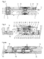
- the cage of this flying tourbillon is made by three bridges, one bridge upper 3, an intermediate bridge 2 and a lower bridge 1 having seen in plan exactly the same shape and dimensions so that once assembled if we look at the cage from above or from below said bridges are perfectly superimposed on each other.
- These three bridges 1,2,3 are assembled by two pillars each comprising an internally threaded sleeve 4 and two 5.5 'screws.
- the exterior surfaces of sockets 4 are fitted in bores 6,7,8 which each include 1,2,3 bridges.
- the length of the sockets 4 is less than the thickness of the three bridges superimposed in the immediate vicinity of their bores 6,7,8 so that in position service assembly the sockets 4 are invisible.
- the 5.5 'screws are screwed into the ends of the sockets 4 and their heads bear against the bridges upper 3 and lower 1 respectively tightening the three bridges 1,2,3 each against the others. In this way, the positioning of the bridges in relation to to others is extremely precise and their assembly is very rigid, their perfect parallelism is also ensured.
- the socket 4 of each pillar has a circular rib 9 on its periphery which facilitates mounting and assembling the bridges 1,2,3.
- This rib 9 of sockets 4 abuts against intermediate bridge 2 and with screw 5 the bridges 1 and 2 can be clamped together and secured to the sockets 4.
- the upper bridge 3 is threaded on the sockets 4 and abuts against the face lower of the intermediate bridge 2.
- the 5 'screws make it possible to block this bridge upper 3 against the intermediate bridge 2.
- the axis 10 of the balance 11 is pivoted between the upper bridge 3 and the bridge lower 1 of the tourbillon cage.
- This axis 10 carries the mobile 12 acting on the anchor 13 which is mounted between the intermediate bridge 2 and the lower bridge 1.
- the exhaust mobile formed by the escape wheel 14 and the pinion exhaust 15 is also pivoted between the intermediate 2 and lower bridges 1.
- the escape wheel 14 cooperates with the anchor 13 while the pinion exhaust 15 is engaged with the fixed seconds wheel 16.
- a spiral spring 30 is fixed by one of its ends to the axis 10 of the pendulum 11 and by its other end using a bolt 31 and a screw 32 on the upper bridge 3 of the tourbillon cage.
- This fixed seconds wheel 16 is fixed, here by screws 17, to the plate 18 a watch movement, plate 18 which is integral with the bridge 19 of the watch movement.
- the watch movement includes a mobile carrying the cage tourbillon whose axis 20 is pivoted between the bridge 19 and the plate 18 of the movement watchmaking.
- This axis 20 carries the board 21 of the mobile carrier cage which is in taken with a pinion 22 of the driving train of the movement driven by a barrel or an engine.
- the lower end of the axis 20 of the mobile carrier of the tourbillon cage has a threaded end 23 and a cylindrical boss 24 coaxial with the axis 20.
- the lower cage 1 of the tourbillon comprises a fixing foot 25 having a bore whose diameter corresponds to that of the boss 24 of the axis 20 of the carrier mobile.
- the fixing foot 25 of the lower tourbillon cage is threaded on the end of the axis 20 of the carrier mobile and adjusts around the boss 24 guaranteeing an exact alignment of the axis of rotation of the cage of the vortex on this axis 20 of the carrier mobile.
- a hollow nut 26 is screwed onto the threaded end of the axis 20 of the carrier mobile and fixed inside the foot of fixing 25. This nut 26 comprises a head coming to bear against the face lower of the lower deck 1 of the cage rigidly fixing the latter on the mobile carrier 20.21.
- the tourbillon cage is thus integral with the carrier mobile 20,21 whose axis is pivoted in bearings 27, 28 carried one by the bridge 19 of the movement and the other by the fixed seconds wheel 16 which is itself fixed on the plate 18 of the movement. Thanks to this assembly, a perfect concentricity of the cage is guaranteed tourbillon with the fixed seconds wheel and therefore with the profile of the teeth this seconds wheel fixes what guarantees a perfect meshing between the pinion exhaust 15 and this fixed seconds wheel 16.
- the tourbillon mechanism described comprises a mobile carrier 20,21 of the tourbillon cage pivoted between two bearings 27,28 one of which 28 is fixed in the fixed seconds wheel 16, which allows perfect coaxiality between the axis of rotation of the tourbillon cage 1,2,3 and the profile of the toothing of the fixed wheel seconds 16.
- the particular attachment of the tourbillon cage by its base attachment to the end of the axis of the carrier 20,21 having a thread and a centering boss 24 using a hollow nut 26 allows alignment perfect between the axis of the carrier 20,21 and the axis of the tourbillon cage.
- the three bridges 1,2,3 having identical shapes, the aesthetics of the cage of the flying tourbillon is pure and sober.
- the bridges 1,2,3, are connected by two pillars 4 but the number of these pillars could be greater depending on the shape of the bridges.
- the seconds wheel 16 is integral with the plate 18 of movement, it is therefore fixed, but in other embodiments this wheel of seconds could be mobile. What matters here is that one of the levels 27.28 of the gear train of the tourbillon cage is integral with this seconds wheel 16.
Landscapes
- Physics & Mathematics (AREA)
- General Physics & Mathematics (AREA)
- Toys (AREA)
- Magnetic Bearings And Hydrostatic Bearings (AREA)
Abstract
Description
Claims (7)
- Mécanisme de tourbillon volant, caractérisé par le fait que la cage du tourbillon est formée de trois ponts (1,2,3) solidairement maintenus et positionnés par des piliers (4,5,5'), le pont intermédiaire (2) étant pris en sandwich entre les ponts supérieur (3) et inférieur (1); par le fait que le pont inférieur comporte un pied de fixation taraudé venant se fixer sur l'extrémité de l'axe (20) d'un mobile porteur de cage (20,21) pivotés entre deux paliers (27,28) dans un mouvement d'horlogerie dont l'un (28) est fixé dans une roue de secondes (16) que comporte le mouvement, cette roue de secondes (16) étant en prise avec un pignon (15) d'un mobile d'échappement (14,15) pivoté entre les ponts intermédiaire et inférieur (1,2) de la cage de tourbillon.
- Mécanisme selon la revendication 1, caractérisé par le fait qu'un balancier (11, 12) et qu'une ancre (13) coopérant avec le balancier et avec la roue d'échappement (14) sont pivotés chacun entre les ponts supérieur (3) et inférieur (1) de la cage de tourbillon.
- Mécanisme selon la revendication 1 ou la revendication 2, caractérisé par le fait que la roue de secondes (16) est fixe, solidaire d'une platine du mouvement.
- Mécanisme selon l'une des revendications précédentes, caractérisé par le fait qu'au droit des piliers (4,5,5') les trois ponts (1,2,3) sont appliqués les uns contre les autres.
- Mécanisme selon la revendication 4, caractérisé par le fait qu'il comporte deux piliers comportant chacun une douille (4) logée dans des alésages pratiqués dans les ponts (1,2,3) et deux vis (5,5') vissées dans un taraudage interne que comporte la douille (4), ces vis prenant appui par leurs têtes sur les ponts supérieur et inférieur (3,1).
- Mécanisme selon la revendication 5, caractérisé par le fait que les douilles (4) comportent une nervure annulaire (9) coopérant avec une portée du pont intermédiaire (2).
- Mécanisme selon l'une des revendications précédentes, caractérisé par le fait que les trois ponts (1,2,3) de la cage de tourbillon présentent vus en plan la même forme et les mêmes dimensions.
Priority Applications (2)
| Application Number | Priority Date | Filing Date | Title |
|---|---|---|---|
| EP20020028888 EP1434113B1 (fr) | 2002-12-23 | 2002-12-23 | Mécanisme de tourbillon et pièce d'horlogerie munie d'un tel mécanisme |
| DE2002606790 DE60206790T2 (de) | 2002-12-23 | 2002-12-23 | Tourbillonmechaismus und Uhr mit solchem Mechanismus |
Applications Claiming Priority (1)
| Application Number | Priority Date | Filing Date | Title |
|---|---|---|---|
| EP20020028888 EP1434113B1 (fr) | 2002-12-23 | 2002-12-23 | Mécanisme de tourbillon et pièce d'horlogerie munie d'un tel mécanisme |
Publications (2)
| Publication Number | Publication Date |
|---|---|
| EP1434113A1 true EP1434113A1 (fr) | 2004-06-30 |
| EP1434113B1 EP1434113B1 (fr) | 2005-10-19 |
Family
ID=32405709
Family Applications (1)
| Application Number | Title | Priority Date | Filing Date |
|---|---|---|---|
| EP20020028888 Expired - Lifetime EP1434113B1 (fr) | 2002-12-23 | 2002-12-23 | Mécanisme de tourbillon et pièce d'horlogerie munie d'un tel mécanisme |
Country Status (2)
| Country | Link |
|---|---|
| EP (1) | EP1434113B1 (fr) |
| DE (1) | DE60206790T2 (fr) |
Cited By (1)
| Publication number | Priority date | Publication date | Assignee | Title |
|---|---|---|---|---|
| CN113671814A (zh) * | 2021-08-04 | 2021-11-19 | 杭州手表有限公司 | 带有环形条盒轮结构的手表 |
Citations (1)
| Publication number | Priority date | Publication date | Assignee | Title |
|---|---|---|---|---|
| CH691831A5 (fr) * | 2000-08-10 | 2001-10-31 | Franck Muller Watchland S A | Pièce d'horlogerie à tourbillon. |
-
2002
- 2002-12-23 DE DE2002606790 patent/DE60206790T2/de not_active Expired - Lifetime
- 2002-12-23 EP EP20020028888 patent/EP1434113B1/fr not_active Expired - Lifetime
Patent Citations (1)
| Publication number | Priority date | Publication date | Assignee | Title |
|---|---|---|---|---|
| CH691831A5 (fr) * | 2000-08-10 | 2001-10-31 | Franck Muller Watchland S A | Pièce d'horlogerie à tourbillon. |
Non-Patent Citations (1)
| Title |
|---|
| HOENIG F: "DAS TOURBILLON: FASZINATION DER DREHUNG - LAUTE BEWUNDERUNG UND VIELE LEISE FRAGEN", UHREN JUWELEN SCHMUCK, BIELEFELDER VERLAGSANSTALT K.G. BIELEFELD, DE, no. 12, 1 December 1992 (1992-12-01), pages 31 - 34, XP000335870, ISSN: 0720-6607 * |
Cited By (2)
| Publication number | Priority date | Publication date | Assignee | Title |
|---|---|---|---|---|
| CN113671814A (zh) * | 2021-08-04 | 2021-11-19 | 杭州手表有限公司 | 带有环形条盒轮结构的手表 |
| CN113671814B (zh) * | 2021-08-04 | 2022-09-13 | 杭州手表有限公司 | 带有环形条盒轮结构的手表 |
Also Published As
| Publication number | Publication date |
|---|---|
| DE60206790T2 (de) | 2006-07-20 |
| EP1434113B1 (fr) | 2005-10-19 |
| DE60206790D1 (de) | 2005-11-24 |
Similar Documents
| Publication | Publication Date | Title |
|---|---|---|
| EP2859412B1 (fr) | Systeme de lunette tournante | |
| EP2233988B1 (fr) | Mouvement horloger à tourbillon muni d'un dispositif de protection contre les chocs | |
| EP1927037B1 (fr) | Dispositif de fixation d'un fond sur une carrure d'une montre | |
| EP2672332A1 (fr) | Système de lunette tournante amelioré | |
| EP3101486B1 (fr) | Coeur d'horlogerie ou de chronographe | |
| EP3407144A2 (fr) | Pièce d'horlogerie comportant un dispositif de verrouillage d'un poussoir | |
| EP1857892A1 (fr) | Montre à élément tournant | |
| EP2824518B1 (fr) | Réglage micrométrique d'ébat de mobile horloger | |
| EP2725433B1 (fr) | Tourbillon volant a balancier volant pour mouvement horloger | |
| EP1460492A1 (fr) | Mécanisme de pièce d'horlogerie à tourbillon | |
| EP1804143A1 (fr) | Pièce d'horlogerie mécanique comprenant des moyens de réglage de l'ébat d'un mobile tournant | |
| EP0626625B1 (fr) | Boîte de montre en métal noble | |
| EP3712712A1 (fr) | Cadran d'une piece d'horlogerie pourvu d'un decor tridimensionnel | |
| EP1434113B1 (fr) | Mécanisme de tourbillon et pièce d'horlogerie munie d'un tel mécanisme | |
| EP1564608A2 (fr) | Piece d'horlogerie munie d'un tourbillon | |
| EP3712714B1 (fr) | Cadran pour une montre universelle | |
| EP0814389B1 (fr) | Mouvement d'horlogerie comportant un tube de guidage entre une platine et un pont | |
| EP1923754B1 (fr) | Mouvement d'horlogerie équipé d'un module d'affichage | |
| EP1055157B1 (fr) | Montre a affichage analogique | |
| CH353310A (fr) | Dispositif d'assemblage et de fixation de deux éléments d'un appareil de précision | |
| WO2015063335A2 (fr) | Mecanisme de tourbillon | |
| CH706597A2 (fr) | Carrure de pièce d'horlogerie avec système de lunette tournante. | |
| EP1980921B1 (fr) | Pièce d'horlogerie comportant une lunette tournante | |
| CH705120B1 (fr) | Mécanisme de tourbillon. | |
| EP3451075B1 (fr) | Mouvement d'horlogerie comportant un tourbillon multiaxial |
Legal Events
| Date | Code | Title | Description |
|---|---|---|---|
| PUAI | Public reference made under article 153(3) epc to a published international application that has entered the european phase |
Free format text: ORIGINAL CODE: 0009012 |
|
| AK | Designated contracting states |
Kind code of ref document: A1 Designated state(s): AT BE BG CH CY CZ DE DK EE ES FI FR GB GR IE IT LI LU MC NL PT SE SI SK TR |
|
| AX | Request for extension of the european patent |
Extension state: AL LT LV MK RO |
|
| 17P | Request for examination filed |
Effective date: 20041030 |
|
| AKX | Designation fees paid |
Designated state(s): CH DE FR GB IT LI |
|
| GRAP | Despatch of communication of intention to grant a patent |
Free format text: ORIGINAL CODE: EPIDOSNIGR1 |
|
| GRAS | Grant fee paid |
Free format text: ORIGINAL CODE: EPIDOSNIGR3 |
|
| GRAA | (expected) grant |
Free format text: ORIGINAL CODE: 0009210 |
|
| AK | Designated contracting states |
Kind code of ref document: B1 Designated state(s): CH DE FR GB IT LI |
|
| PG25 | Lapsed in a contracting state [announced via postgrant information from national office to epo] |
Ref country code: GB Free format text: LAPSE BECAUSE OF FAILURE TO SUBMIT A TRANSLATION OF THE DESCRIPTION OR TO PAY THE FEE WITHIN THE PRESCRIBED TIME-LIMIT Effective date: 20051019 Ref country code: IT Free format text: LAPSE BECAUSE OF FAILURE TO SUBMIT A TRANSLATION OF THE DESCRIPTION OR TO PAY THE FEE WITHIN THE PRESCRIBED TIME-LIMIT;WARNING: LAPSES OF ITALIAN PATENTS WITH EFFECTIVE DATE BEFORE 2007 MAY HAVE OCCURRED AT ANY TIME BEFORE 2007. THE CORRECT EFFECTIVE DATE MAY BE DIFFERENT FROM THE ONE RECORDED. Effective date: 20051019 |
|
| REG | Reference to a national code |
Ref country code: GB Ref legal event code: FG4D Free format text: NOT ENGLISH |
|
| REG | Reference to a national code |
Ref country code: CH Ref legal event code: EP |
|
| REG | Reference to a national code |
Ref country code: CH Ref legal event code: NV Representative=s name: MICHELI & CIE INGENIEURS-CONSEILS |
|
| REF | Corresponds to: |
Ref document number: 60206790 Country of ref document: DE Date of ref document: 20051124 Kind code of ref document: P |
|
| GBV | Gb: ep patent (uk) treated as always having been void in accordance with gb section 77(7)/1977 [no translation filed] |
Effective date: 20051019 |
|
| PLBE | No opposition filed within time limit |
Free format text: ORIGINAL CODE: 0009261 |
|
| STAA | Information on the status of an ep patent application or granted ep patent |
Free format text: STATUS: NO OPPOSITION FILED WITHIN TIME LIMIT |
|
| 26N | No opposition filed |
Effective date: 20060720 |
|
| REG | Reference to a national code |
Ref country code: FR Ref legal event code: PLFP Year of fee payment: 14 |
|
| REG | Reference to a national code |
Ref country code: FR Ref legal event code: PLFP Year of fee payment: 15 |
|
| REG | Reference to a national code |
Ref country code: FR Ref legal event code: PLFP Year of fee payment: 16 |
|
| PGFP | Annual fee paid to national office [announced via postgrant information from national office to epo] |
Ref country code: DE Payment date: 20181210 Year of fee payment: 17 |
|
| PGFP | Annual fee paid to national office [announced via postgrant information from national office to epo] |
Ref country code: SI Payment date: 20181019 Year of fee payment: 7 |
|
| REG | Reference to a national code |
Ref country code: DE Ref legal event code: R119 Ref document number: 60206790 Country of ref document: DE |
|
| PG25 | Lapsed in a contracting state [announced via postgrant information from national office to epo] |
Ref country code: DE Free format text: LAPSE BECAUSE OF NON-PAYMENT OF DUE FEES Effective date: 20200701 Ref country code: FR Free format text: LAPSE BECAUSE OF NON-PAYMENT OF DUE FEES Effective date: 20191231 |
|
| PGFP | Annual fee paid to national office [announced via postgrant information from national office to epo] |
Ref country code: CH Payment date: 20211221 Year of fee payment: 20 |
|
| REG | Reference to a national code |
Ref country code: CH Ref legal event code: PL |