EP1433550B1 - A method and a device for continuous casting of metals - Google Patents
A method and a device for continuous casting of metals Download PDFInfo
- Publication number
- EP1433550B1 EP1433550B1 EP04005408A EP04005408A EP1433550B1 EP 1433550 B1 EP1433550 B1 EP 1433550B1 EP 04005408 A EP04005408 A EP 04005408A EP 04005408 A EP04005408 A EP 04005408A EP 1433550 B1 EP1433550 B1 EP 1433550B1
- Authority
- EP
- European Patent Office
- Prior art keywords
- magnetic field
- liquid metal
- varying
- magnet members
- mould
- Prior art date
- Legal status (The legal status is an assumption and is not a legal conclusion. Google has not performed a legal analysis and makes no representation as to the accuracy of the status listed.)
- Expired - Lifetime
Links
Images


Classifications
-
- B—PERFORMING OPERATIONS; TRANSPORTING
- B22—CASTING; POWDER METALLURGY
- B22D—CASTING OF METALS; CASTING OF OTHER SUBSTANCES BY THE SAME PROCESSES OR DEVICES
- B22D11/00—Continuous casting of metals, i.e. casting in indefinite lengths
- B22D11/10—Supplying or treating molten metal
- B22D11/11—Treating the molten metal
- B22D11/114—Treating the molten metal by using agitating or vibrating means
- B22D11/115—Treating the molten metal by using agitating or vibrating means by using magnetic fields
Definitions
- the present invention relates to a method and a device for continuous casting of metals according to the preambles of the appended independent method and device claims.
- a liquid metal is supplied to a mould, in which it is cooled and shaped to an elongated string.
- the string is called "billet", “bloom” or “slab”.
- a primary flow of hot, liquid metal is during the casting delivered to a cooled mould, in which a metal is cooled and at least partially solidifies into an elongated string.
- the cooled and partially solidified string leaves the mould continuously. At the point where the string leaves the mould it has at least a mechanically self-supporting solidified skin surrounding a centre part not solidified.
- the cooled mould is open at two opposite ends as seen in the casting direction and preferably connected to means for supporting the mould and means for supplying cooling means to the mould and the support means.
- the mould is preferably made of an alloy with a copper base and a high thermal conductivity.
- the liquid metal is supplied to the mould from a casting box through a tube extending down into the mould.
- the tube extends preferably that far into the mould that it projects into the liquid metal preferably present there.
- the primary flow goes downwardly in the casting direction, while the secondary flow goes from the region of the walls of the mould upwardly towards the surface of the metal bath located therein and downwardly.
- periodic velocity oscillations are created during the casting sequence.
- upper and lower loops in which the liquid metal flows around are formed in a way known per se.
- Velocity variations caused by oscillating flow in the mould gives rise to pressure variations at the meniscus, and meniscus height variations. At high meniscus velocities, this results in
- the oscillating flow results in an asymmetric velocity downwardly in the mould.
- the velocity may in some positions at one narrow side get substantially higher than at the other. This gives rise to a strong transport downwardly of enclosures and gas bubbles accompanied by a decreased slag quality.
- the prior art relates to different devices and methods for influencing the primary and the secondary flows, respectively, in the liquid metal in the mould.
- the prior art utilizes for this devices for applying substantially static magnetic fields during the casting sequence over at least a part of the liquid metal contained in the mould. It is for instance known through the Swedish patent publication SE 436 251 to arrange a static direct current magnetic field or permanent magnetic field at the mould. It may as an alternative be formed by a low frequency alternating current field having a frequency below 1 Hz. When the metal flowing in passes this field the movement of the tap jet into the rest of the liquid metal is retarded, wherethrough the flow picture is influenced favourably for the casting sequence. This technique has then been further developed.
- the magnets used for the generation of the magnetic field have for example been placed so that a magnetic field at different levels of the mould in the casting direction has been obtained, whereby specific local movements in the liquid metal could be influenced separately through the respective magnetic field. It has also been proposed to arrange the magnets and the yokes connecting them in such a way that the magnetic fields extend in the casting direction instead of transversely thereto.
- US 5722480 describes a process for continuously casting a molten metal which suppresses the instability of the initial solidification and stably improves the lubrication and the surface properties of the cast metal, and an apparatus therefore.
- an alternating current is applied to an electromagnetic coil which is provided so that it surrounds a continuous casting mold wall or is embedded in the side wall of the mold.
- An electromagnetic force is exerted on the molten metal poured into the mold which either oscillates in a constant mode or does not oscillate.
- the amplitude or waveform of the alternating current to be applied is periodically changed.
- An object of the present invention is to provide a method substantially disturbing and thereby reducing the generation of periodical oscillations and resonance phenomena associated therewith, which are commonly existing in a liquid metal in a mould in connection with continuous casting of metals.
- This object is obtained by means of a method of the type defined in the introduction, which is characterized in that the varying magnetic field is provided with a stochastically varying frequency.
- the field will function as a damper in the liquid metal.
- the application of the magnetic field is carried out periodically.
- the periodicity may be adapted to the periodicity of the oscillations, which normally for casting steel slabs is in the order of 1-30 seconds.
- the field is applied periodically for disturbing and eliminating oscillations in the liquid metal without changing the main flow topology therefor.
- the flow topology may be changed, for example by means of strong , static magnetic field or a moving field.
- the varying magnetic field is applied at irregular intervals during the casting sequence. Thanks to the irregularity of the application it is avoided to regularly amplify certain regular, periodical oscillations in the liquid metal.
- the varying magnetic field causes instead thanks to the regularity thereof a disturbance of such regular natural oscillations in the liquid metal.
- the irregular application of the magnetic field is carried out at random times.
- the magnetic field applied randomly counteracts and disturbs efficiently the generation of periodical oscillations.
- the random application of the magnetic field results in a minimum risk of possibly amplifying any natural oscillation present in the liquid metal during any extended time.
- the periodical application of the magnetic field is carried out at predetermined times. These times are preferably times known in advance, at which periodical oscillations in the liquid metal are in a certain critical stage, for instance when resonance phenomena caused by said natural oscillations start or may start to occur.
- the predetermined times are then based on practical observations or calculations of the time for the occurrence of such critical stages in the liquid metal under given casting conditions or measurements of meniscus deformation.
- the application is carried out upon detection of a certain state in the liquid metal.
- Said state is preferably a predetermined detectable movement in the liquid metal or as an alternative of the meniscus.
- the varying magnetic field is provided with a stochastically varying amplitude. The probability for disturbing and not amplifying the natural oscillations generated in the liquid metal during the casting sequence is thereby increased.
- the varying magnetic field is given a frequency being in the order of 10-10 3 times higher than the frequency of the oscillation or oscillations in the melt intended to be disturbed thereby. These are normally of the type wide-band spectrum. A very reliable disturbance of said oscillations of the liquid metal is thereby obtained.
- the magnetic field may then advantageously be applied only during a restricted part of the period of the oscillation or oscillations and nevertheless give a satisfying and reliable disturbance influence.
- a further object of the invention is to provide a device, by means of which natural oscillations and resonance phenomena associated therewith of a liquid metal in the mould during continuous casting of metals may be disturbed and prevented from being generated.
- This object is obtained by means of a device of the type defined in the introduction, which is characterized in that the magnetic members are adapted to generate a magnetic field with a stochastically varying frequency. Thanks to the fact that the magnetic field varies it may easily be controlled, i.e. be given such an amplitude and frequency, that the periodical oscillations existing or generated in the liquid metal are efficiently disturbed.
- the magnet members are arranged in such a way that they generate the varying magnetic field periodically during the casting sequence.
- the periodicity is advantageously adapted to the periodicity of the oscillations, which is in the order of 1-30 seconds when casting steel slabs.
- the magnetic members are adapted to generate the varying magnetic field at irregular intervals. This disturbs efficiently a generation of each natural oscillation, since they will with a high probability be in off-phase with the periodical oscillations existing in the liquid metal.
- the magnet members are adapted to generate a magnetic field having a stochastically varying amplitude. They are preferably also adapted to generate a magnetic field having a varying frequency, for example stochastically varying frequency, within a given frequency interval. Thanks to the variation of the amplitude and/or frequency of the magnetic field, or the current used to generate the magnetic field, a very reliable disturbance of the natural oscillations in the liquid metal is obtained, at the same time as an amplification of possibly natural oscillations in the liquid metal are efficiently avoided.
- the magnet members are adapted to generate a substantially static magnetic field, onto which the varying magnetic field is superposed.
- the static magnetic field is preferably used for influencing the so-called primary flows and secondary flows in the liquid metal in the mould, which the liquid metal supplied thereto gives rise to.
- the same type of basic equipment, which has according to the prior art been used for achieving such an influence, may accordingly advantageously be used for the combined function aimed at, since both a static magnetic field and varying magnetic field superposed thereon are applied to the liquid metal in the mould.
- the varying magnetic field has a frequency in the order of 10-10 3 times higher than the frequency of the oscillation or the oscillations of the liquid metal to be disturbed thereby. A very reliable disturbance of the natural oscillations in the liquid metal is thereby obtained.
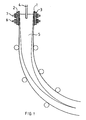
- Figs 1-3 show a device for continuous casting of metals, such as for example steel.
- the device comprises a mould, which defines a cylinder composed of four opposite walls.
- the mould is preferably made of a copper alloy or any other alloy having a suitable thermal conductivity and thermal resistance. Outside at least two opposite walls of the mould 1 members 2, 3 for cooling said walls are arranged.
- the cooling members 2, 3 may comprise any type of supporting frame, through which cooling channels for transport of the cooling medium, such as water, may be arranged. Such channels may possibly be arranged so that they allow the cooling medium to flow directly towards the external surfaces of said walls for cooling thereof.
- the device also comprises a member 4, here a so-called “submerged entry nozzle, SEN", through which a liquid metal is supplied from a container not shown to the space defined by the mould.
- a member 4 here a so-called “submerged entry nozzle, SEN"
- SEN submerged entry nozzle
- the mould 1 is filled with metal.
- This metal is present mainly as a liquid metal, but along the interface to the mould 1 it defines a solidified or partially solidified outer layer, a so called skin, which grows gradually in thickness in the casting direction.
- the mould 1 is then adapted to carry out a substantially vertical oscillating movement while a casting string 5 consisting of liquid metal and the solidified outer layer surrounding this successively is fed out from one end of the mould 1.
- the member 4 extends from above into the liquid metal present in the mould 1. Further liquid metal is supplied to the mould 1 through the member 4. The liquid metal flowing into the liquid metal in the mould 1 from the member 4 generates a primary flow, which is illustrated through the arrows 18, and a secondary flow, illustrated through the arrows 19, in the liquid metal already present in the casting mould 1. These natural oscillations are of the type wide-band spectrum. Since resonance phenomena occur as a consequence of these oscillations in the liquid metal, it may result in the transport of large bubbles, which contain gases or slag, downwardly into the casting string 5. As a result thereof enclosures, bubbles or argon containing enclosures and slag from the meniscus are present in the finally entirely solidified casting string 5.
- Velocity variations caused by the oscillating flow in the mould may give rise to pressure variations at the meniscus and height variations of the meniscus. This leads at high meniscus velocities to slag drawdown, an uneven slag thickness, an uneven skin thickness and the risk of crack formation. Furthermore, the oscillating flow results in an asymmetric velocity in the mould. The velocity at one narrow side may in certain positions be substantially higher than at the other narrow side. This results in a powerful transport downwardly of the enclosures and gas bubbles accompanied by a decreased slag quality.
- the device comprises a first set of magnet members 6, which are adapted to apply or generate a varying magnetic field across the liquid metal in the mould 1, i.e. transversal to the casting direction.
- the magnet members are according to a preferred embodiment adapted to irregularly, e.g. at random times but within given limits in the time, generate a varying magnetic field with a random amplitude within at least a predetermined amplitude range.
- the magnet members may also advantageously be designed to generate the magnetic field in such a way that it has a frequency varying randomly, in which also the frequency is within at least a predetermined range.
- the lowest frequency, or at least the average frequency, should however, exceed 1 Hz, and preferably exceed 10 Hz.
- the magnet members may be arranged in such a way that they generate a magnetic field with a determined amplitude and frequency, for example a magnetic field which may be described by a square wave or a sinus-shaped wave, such as in Figs 6 and 7.
- the device may also comprise means (not shown) for activating the magnet members to generate said magnetic field at predetermined periods.
- Said activating means may then comprise means 20 for detecting a certain condition or for predicting the appearance of a certain condition by modelling/calculation, for example a certain movement in the liquid metal or of a member 4, in which activation of the magnet members is to be carried out and means 21 for controlling said activation.
- a device adapting the disturbance by natural oscillations existing thereof to the conditions prevailing for the moment in the liquid metal is thereby obtained.
- the device also comprises a second set 7 of magnet members.
- This second set 7 is arranged closer to the upper surface of the liquid metal in the mould 1 than the first set 6 and is arranged substantially on the same level as that part of the member 4 that projects down into the liquid metal.
- the first set 6 of magnet members is arranged immediately after the member 4 as seen in the casting direction, in this case below the opening or openings of the member 4 for letting the liquid metal out.
- the second set 7 of magnet members is advantageously arranged to generate a magnetic field similar to any of the magnetic fields described above and generated by the first set 6 of the magnet members.
- Fig 3 shows a set of magnet members 6 or 7, seen from above.
- the set 6, 7 comprises two couples of magnet cores, preferably iron cores 8, 9 and 10, 11.
- a winding 12-15 of an electric conductor is arranged on each of the said cores 8-11 .
- Said windings 12-15 are fed from one or several (not shown) current sources with current, preferably direct current varying in time, for generating a magnetic field extending across, i.e. through, the liquid metal in the mould 1.
- the cores 8, 9 and 10, 11 of the respective couple are connected to each other through yokes or leg members 16, 17.
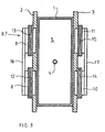
- the magnet cores and the windings are arranged in a way known per se, as appears from Fig 3, but they could of course be arranged in another way and possibly comprise more or fewer individual magnet cores and windings arranged thereon.
- second arrangement of yoke members 16, 17 and magnet cores 8-11 with respect to each other is possible, for example for generating the magnetic field on several levels in the casting direction, or for generating one or several magnetic fields extending in the casting direction.
- the magnet members have, arranged in the way appearing from Figs 1-3, been adapted to generate a generally static or periodic low-frequency (f ⁇ 1 Hz) magnetic field across the liquid metal in the mould 1 in order to influence the primary and secondary flows described earlier in the liquid metal. Problems associated with said flows and described within the prior art are thereby solved.
- the sets 6, 7 of magnet members in the device according to the present invention are preferably also arranged to generate a substantially static magnetic field across the liquid metal in the mould 1 to influence the primary and secondary flows in a way favourable for the casting sequence.
- the different types of varying magnetic fields generated by the sets of magnet members 6, 7 are superposed onto said static magnetic field.
- the static magnetic field is shown in Fig 4, while different types of varying magnetic fields, which may be superposed onto the static magnetic field, are shown in Fig 5-7.
- the varying magnetic fields shown in Figs 5-7 are examples of how such magnetic fields may be generated according to the invention.
- the magnetic field according to Fig 5 is generated at random times, has a stochastic amplitude within a given range, as well as a stochastic frequency within a given range.
- the magnetic fields according to Fig 6 have, however, a given constant amplitude and frequency, which is also the case for the magnetic field described through Fig 7.
- the diagrams shown in Figs 4-7 may also be described to show the current applied to the conductor windings 12-15 for generating said magnetic fields.
- the frequency of the varying magnetic field is preferably higher than the frequency of the oscillation or the oscillations of the liquid metal to be disturbed by said magnetic field.
- the frequency of the magnetic field is preferably in the order of 10-10 3 times higher than the frequency of said oscillations.
- the oscillations have a frequency in the order of 0.01-10 Hz. Since the frequency, or the average frequency, of the magnetic field is lower or of substantially the same size as said frequencies, it should be generated so that it is in opposite phase, or at least not entirely in phase with said oscillations.
- the magnet members are advantageously adapted to generate one or several magnetic fields adapted to the specific oscillations conditions prevailing in the different parts of the liquid metal where exactly these magnetic fields propagate.
- Fig 8 shows an alternative embodiment of the device according to the invention, where only one set of magnet members 22 is arranged at only one level at the mould in the casting direction.
- the set 22 is arranged in a region downstream of the opening/openings of the member 4.
- the magnetic field is fixed or stationary, i.e. it does not move and thereby agitate the liquid metal, which is the case for conventional agitators.
- the member 4 may be arranged in such a way that it does not project into the liquid metal in the mould, by which a free tap jet reaches the liquid metal.
- the natural oscillations which the invention aims to damp or disturb, comprise large movements within the liquid metal, where large portions in the liquid metal with certain flowing conditions are displaced mutually more or less periodically, whereby unfavourable casting conditions occur.
- the varying magnetic field is preferably superposed onto a substantially static magnetic field normally being constantly applied to the liquid metal.
- a substantially static magnetic field normally being constantly applied to the liquid metal.
Abstract
Description
- The present invention relates to a method and a device for continuous casting of metals according to the preambles of the appended independent method and device claims.
- In continuous casting a liquid metal is supplied to a mould, in which it is cooled and shaped to an elongated string. Depending upon the cross section dimensions the string is called "billet", "bloom" or "slab". A primary flow of hot, liquid metal is during the casting delivered to a cooled mould, in which a metal is cooled and at least partially solidifies into an elongated string. The cooled and partially solidified string leaves the mould continuously. At the point where the string leaves the mould it has at least a mechanically self-supporting solidified skin surrounding a centre part not solidified. The cooled mould is open at two opposite ends as seen in the casting direction and preferably connected to means for supporting the mould and means for supplying cooling means to the mould and the support means. The mould is preferably made of an alloy with a copper base and a high thermal conductivity.
- The liquid metal is supplied to the mould from a casting box through a tube extending down into the mould. The tube extends preferably that far into the mould that it projects into the liquid metal preferably present there. When the liquid metal from the tube flows into the liquid metal already present in the mould, it generates a so-called primary flow and a so-called secondary flow. The primary flow goes downwardly in the casting direction, while the secondary flow goes from the region of the walls of the mould upwardly towards the surface of the metal bath located therein and downwardly. In different parts of the metal bath present in the mould periodic velocity oscillations are created during the casting sequence. Thus, upper and lower loops in which the liquid metal flows around are formed in a way known per se. As a consequence of resonance phenomena, which are associated with periodical oscillations of such loops, large bubbles, for instance argon bubbles, oxide enclosures from the casting tube and slag from the meniscus will be transported far downwardly in the casting direction, i.e. far downwardly in the casting string initially formed in the mould. This results in enclosures and irregularities in the final, solidified casting string.
- Velocity variations caused by oscillating flow in the mould gives rise to pressure variations at the meniscus, and meniscus height variations. At high meniscus velocities, this results in
- (a) draw-down of slag,
- (b) uneven slag thickness,
- (c) uneven skin thickness, and
- (d) a risk of crack formation.
- Furthermore, the oscillating flow results in an asymmetric velocity downwardly in the mould. The velocity may in some positions at one narrow side get substantially higher than at the other. This gives rise to a strong transport downwardly of enclosures and gas bubbles accompanied by a decreased slag quality.
- The prior art relates to different devices and methods for influencing the primary and the secondary flows, respectively, in the liquid metal in the mould. The prior art utilizes for this devices for applying substantially static magnetic fields during the casting sequence over at least a part of the liquid metal contained in the mould. It is for instance known through the Swedish patent publication SE 436 251 to arrange a static direct current magnetic field or permanent magnetic field at the mould. It may as an alternative be formed by a low frequency alternating current field having a frequency below 1 Hz. When the metal flowing in passes this field the movement of the tap jet into the rest of the liquid metal is retarded, wherethrough the flow picture is influenced favourably for the casting sequence. This technique has then been further developed. The magnets used for the generation of the magnetic field have for example been placed so that a magnetic field at different levels of the mould in the casting direction has been obtained, whereby specific local movements in the liquid metal could be influenced separately through the respective magnetic field. It has also been proposed to arrange the magnets and the yokes connecting them in such a way that the magnetic fields extend in the casting direction instead of transversely thereto.
- US 5722480 describes a process for continuously casting a molten metal which suppresses the instability of the initial solidification and stably improves the lubrication and the surface properties of the cast metal, and an apparatus therefore. In the process for continuously casting a molten metal an alternating current is applied to an electromagnetic coil which is provided so that it surrounds a continuous casting mold wall or is embedded in the side wall of the mold. An electromagnetic force is exerted on the molten metal poured into the mold which either oscillates in a constant mode or does not oscillate. The amplitude or waveform of the alternating current to be applied is periodically changed.
- An object of the present invention is to provide a method substantially disturbing and thereby reducing the generation of periodical oscillations and resonance phenomena associated therewith, which are commonly existing in a liquid metal in a mould in connection with continuous casting of metals.
- This object is obtained by means of a method of the type defined in the introduction, which is characterized in that the varying magnetic field is provided with a stochastically varying frequency. The field will function as a damper in the liquid metal.
- According to a preferred embodiment of the method the application of the magnetic field is carried out periodically. The periodicity may be adapted to the periodicity of the oscillations, which normally for casting steel slabs is in the order of 1-30 seconds. The field is applied periodically for disturbing and eliminating oscillations in the liquid metal without changing the main flow topology therefor. The flow topology may be changed, for example by means of strong , static magnetic field or a moving field.
- According to a further preferred embodiment of the method the varying magnetic field is applied at irregular intervals during the casting sequence. Thanks to the irregularity of the application it is avoided to regularly amplify certain regular, periodical oscillations in the liquid metal. The varying magnetic field causes instead thanks to the regularity thereof a disturbance of such regular natural oscillations in the liquid metal.
- According to a further preferred embodiment the irregular application of the magnetic field is carried out at random times. The magnetic field applied randomly counteracts and disturbs efficiently the generation of periodical oscillations. The random application of the magnetic field results in a minimum risk of possibly amplifying any natural oscillation present in the liquid metal during any extended time.
- According to an alternative embodiment of the method the periodical application of the magnetic field is carried out at predetermined times. These times are preferably times known in advance, at which periodical oscillations in the liquid metal are in a certain critical stage, for instance when resonance phenomena caused by said natural oscillations start or may start to occur. The predetermined times are then based on practical observations or calculations of the time for the occurrence of such critical stages in the liquid metal under given casting conditions or measurements of meniscus deformation.
- According to a further preferred embodiment of the method the application is carried out upon detection of a certain state in the liquid metal. Said state is preferably a predetermined detectable movement in the liquid metal or as an alternative of the meniscus.
- According to a further preferred embodiment the varying magnetic field is provided with a stochastically varying amplitude. The probability for disturbing and not amplifying the natural oscillations generated in the liquid metal during the casting sequence is thereby increased.
- According to a further preferred embodiment the varying magnetic field is given a frequency being in the order of 10-103 times higher than the frequency of the oscillation or oscillations in the melt intended to be disturbed thereby. These are normally of the type wide-band spectrum. A very reliable disturbance of said oscillations of the liquid metal is thereby obtained. The magnetic field may then advantageously be applied only during a restricted part of the period of the oscillation or oscillations and nevertheless give a satisfying and reliable disturbance influence.
- A further object of the invention is to provide a device, by means of which natural oscillations and resonance phenomena associated therewith of a liquid metal in the mould during continuous casting of metals may be disturbed and prevented from being generated.
- This object is obtained by means of a device of the type defined in the introduction, which is characterized in that the magnetic members are adapted to generate a magnetic field with a stochastically varying frequency. Thanks to the fact that the magnetic field varies it may easily be controlled, i.e. be given such an amplitude and frequency, that the periodical oscillations existing or generated in the liquid metal are efficiently disturbed.
- According to a preferred embodiment the magnet members are arranged in such a way that they generate the varying magnetic field periodically during the casting sequence. The periodicity is advantageously adapted to the periodicity of the oscillations, which is in the order of 1-30 seconds when casting steel slabs.
- According to a further preferred embodiment the magnetic members are adapted to generate the varying magnetic field at irregular intervals. This disturbs efficiently a generation of each natural oscillation, since they will with a high probability be in off-phase with the periodical oscillations existing in the liquid metal.
- According to a further preferred embodiment the magnet members are adapted to generate a magnetic field having a stochastically varying amplitude. They are preferably also adapted to generate a magnetic field having a varying frequency, for example stochastically varying frequency, within a given frequency interval. Thanks to the variation of the amplitude and/or frequency of the magnetic field, or the current used to generate the magnetic field, a very reliable disturbance of the natural oscillations in the liquid metal is obtained, at the same time as an amplification of possibly natural oscillations in the liquid metal are efficiently avoided.
- According to a further preferred embodiment the magnet members are adapted to generate a substantially static magnetic field, onto which the varying magnetic field is superposed. The static magnetic field is preferably used for influencing the so-called primary flows and secondary flows in the liquid metal in the mould, which the liquid metal supplied thereto gives rise to. The same type of basic equipment, which has according to the prior art been used for achieving such an influence, may accordingly advantageously be used for the combined function aimed at, since both a static magnetic field and varying magnetic field superposed thereon are applied to the liquid metal in the mould.
- According to a further preferred embodiment of the device the varying magnetic field has a frequency in the order of 10-103 times higher than the frequency of the oscillation or the oscillations of the liquid metal to be disturbed thereby. A very reliable disturbance of the natural oscillations in the liquid metal is thereby obtained.
- Further characteristics and advantages of the invention appear from the other dependent claims and the following detailed description.
- The present invention will hereinafter be described as an example with reference to the appended drawings.
-
- Fig 1 is a schematic cross section view from one side of a device for continuous casting of metals,
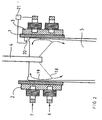
- Fig 2 is a cross section view from the side of an upper part of the device according to Fig 1,
- Fig 3 is a view from above of the device according to Figs 1 and 2,
- Fig 4 is a diagram showing a static magnetic field, or the direct current used for generating this field, on which a varying magnetic field is superposed,
- Figs 5-7 are diagrams showing how a varying magnetic field, or the current varying said magnetic field, may be varied in the time according to different embodiments of the invention and
- Fig 8 is a schematic lateral cross section view showing a device having magnet members at only one level.
- Figs 1-3 show a device for continuous casting of metals, such as for example steel. The device comprises a mould, which defines a cylinder composed of four opposite walls. The mould is preferably made of a copper alloy or any other alloy having a suitable thermal conductivity and thermal resistance. Outside at least two opposite walls of the mould 1
members cooling members - The device also comprises a
member 4, here a so-called "submerged entry nozzle, SEN", through which a liquid metal is supplied from a container not shown to the space defined by the mould. During the casting sequence the mould 1 is filled with metal. This metal is present mainly as a liquid metal, but along the interface to the mould 1 it defines a solidified or partially solidified outer layer, a so called skin, which grows gradually in thickness in the casting direction. The mould 1 is then adapted to carry out a substantially vertical oscillating movement while acasting string 5 consisting of liquid metal and the solidified outer layer surrounding this successively is fed out from one end of the mould 1. - The
member 4 extends from above into the liquid metal present in the mould 1. Further liquid metal is supplied to the mould 1 through themember 4. The liquid metal flowing into the liquid metal in the mould 1 from themember 4 generates a primary flow, which is illustrated through thearrows 18, and a secondary flow, illustrated through thearrows 19, in the liquid metal already present in the casting mould 1. These natural oscillations are of the type wide-band spectrum. Since resonance phenomena occur as a consequence of these oscillations in the liquid metal, it may result in the transport of large bubbles, which contain gases or slag, downwardly into thecasting string 5. As a result thereof enclosures, bubbles or argon containing enclosures and slag from the meniscus are present in the finally entirely solidified castingstring 5. Velocity variations caused by the oscillating flow in the mould may give rise to pressure variations at the meniscus and height variations of the meniscus. This leads at high meniscus velocities to slag drawdown, an uneven slag thickness, an uneven skin thickness and the risk of crack formation. Furthermore, the oscillating flow results in an asymmetric velocity in the mould. The velocity at one narrow side may in certain positions be substantially higher than at the other narrow side. This results in a powerful transport downwardly of the enclosures and gas bubbles accompanied by a decreased slag quality. - For avoiding the problem mentioned above the device comprises a first set of magnet members 6, which are adapted to apply or generate a varying magnetic field across the liquid metal in the mould 1, i.e. transversal to the casting direction. The magnet members are according to a preferred embodiment adapted to irregularly, e.g. at random times but within given limits in the time, generate a varying magnetic field with a random amplitude within at least a predetermined amplitude range.
- The magnet members may also advantageously be designed to generate the magnetic field in such a way that it has a frequency varying randomly, in which also the frequency is within at least a predetermined range. The lowest frequency, or at least the average frequency, should however, exceed 1 Hz, and preferably exceed 10 Hz. As an alternative, the magnet members may be arranged in such a way that they generate a magnetic field with a determined amplitude and frequency, for example a magnetic field which may be described by a square wave or a sinus-shaped wave, such as in Figs 6 and 7. The device may also comprise means (not shown) for activating the magnet members to generate said magnetic field at predetermined periods. Said activating means may then comprise means 20 for detecting a certain condition or for predicting the appearance of a certain condition by modelling/calculation, for example a certain movement in the liquid metal or of a
member 4, in which activation of the magnet members is to be carried out and means 21 for controlling said activation. A device adapting the disturbance by natural oscillations existing thereof to the conditions prevailing for the moment in the liquid metal is thereby obtained. - The device also comprises a
second set 7 of magnet members. Thissecond set 7 is arranged closer to the upper surface of the liquid metal in the mould 1 than the first set 6 and is arranged substantially on the same level as that part of themember 4 that projects down into the liquid metal. The first set 6 of magnet members is arranged immediately after themember 4 as seen in the casting direction, in this case below the opening or openings of themember 4 for letting the liquid metal out. Also thesecond set 7 of magnet members is advantageously arranged to generate a magnetic field similar to any of the magnetic fields described above and generated by the first set 6 of the magnet members. - Fig 3 shows a set of
magnet members 6 or 7, seen from above. As appears from Fig 3, theset 6, 7 comprises two couples of magnet cores, preferablyiron cores cores leg members yoke members - According to prior art the magnet members have, arranged in the way appearing from Figs 1-3, been adapted to generate a generally static or periodic low-frequency (f < 1 Hz) magnetic field across the liquid metal in the mould 1 in order to influence the primary and secondary flows described earlier in the liquid metal. Problems associated with said flows and described within the prior art are thereby solved. The
sets 6, 7 of magnet members in the device according to the present invention are preferably also arranged to generate a substantially static magnetic field across the liquid metal in the mould 1 to influence the primary and secondary flows in a way favourable for the casting sequence. The different types of varying magnetic fields generated by the sets ofmagnet members 6, 7 are superposed onto said static magnetic field. The static magnetic field is shown in Fig 4, while different types of varying magnetic fields, which may be superposed onto the static magnetic field, are shown in Fig 5-7. The varying magnetic fields shown in Figs 5-7 are examples of how such magnetic fields may be generated according to the invention. The magnetic field according to Fig 5 is generated at random times, has a stochastic amplitude within a given range, as well as a stochastic frequency within a given range. The magnetic fields according to Fig 6 have, however, a given constant amplitude and frequency, which is also the case for the magnetic field described through Fig 7. The diagrams shown in Figs 4-7 may also be described to show the current applied to the conductor windings 12-15 for generating said magnetic fields. - The frequency of the varying magnetic field is preferably higher than the frequency of the oscillation or the oscillations of the liquid metal to be disturbed by said magnetic field. The frequency of the magnetic field is preferably in the order of 10-103 times higher than the frequency of said oscillations. The oscillations have a frequency in the order of 0.01-10 Hz. Since the frequency, or the average frequency, of the magnetic field is lower or of substantially the same size as said frequencies, it should be generated so that it is in opposite phase, or at least not entirely in phase with said oscillations.
- In some cases, for example when natural oscillations having different amplitudes and frequencies are present in different parts of the liquid metal, the magnet members are advantageously adapted to generate one or several magnetic fields adapted to the specific oscillations conditions prevailing in the different parts of the liquid metal where exactly these magnetic fields propagate.
- Fig 8 shows an alternative embodiment of the device according to the invention, where only one set of
magnet members 22 is arranged at only one level at the mould in the casting direction. Theset 22 is arranged in a region downstream of the opening/openings of themember 4. - A plurality of modifications of the device according to the invention and the method according to the invention will of course be apparent to a man skilled in the art while these are still within the scope of protection of the present invention, such as this is defined in the appended claims.
- It is important to note that the magnetic field is fixed or stationary, i.e. it does not move and thereby agitate the liquid metal, which is the case for conventional agitators.
- It is to be understood that the
member 4 may be arranged in such a way that it does not project into the liquid metal in the mould, by which a free tap jet reaches the liquid metal. - It should also be noticed that the natural oscillations, which the invention aims to damp or disturb, comprise large movements within the liquid metal, where large portions in the liquid metal with certain flowing conditions are displaced mutually more or less periodically, whereby unfavourable casting conditions occur.
- The varying magnetic field is preferably superposed onto a substantially static magnetic field normally being constantly applied to the liquid metal. By applying the varying magnetic field in pulses or periodically the strength of the static field may be reduced somewhat at least periodically, while establishing desired casting conditions. This may be an advantage with respect to the flow topology as well as the energy consumption.
Claims (22)
- A method for continuous casting of metals, in which liquid metal is supplied as a jet to a mould (1) which already contains a further liquid metal, where a magnetic field varying with time and being substantially fixed in the room is applied by means of magnet members (6, 7) to the liquid metal in the mould for preventing natural oscillations of the liquid metal from being generated, characterized in that the varying magnetic field is provided with a stochastically varying frequency.
- A method according to claim 1, characterized in that a substantially static magnetic field is applied to the liquid metal, and that said varying magnetic field is superposed onto the substantially static magnetic field.
- A method according to claim 1 or 2, characterized in that the application of the varying magnetic field is carried out periodically.
- A method according to any of claims 1-3, characterized in that the varying magnetic field is applied at irregular intervals during the casting sequence.
- A method according to claim 4, characterized in that said irregular application is carried out at random times.
- A method according to claim 3 or 4, characterized in that said periodic application is carried out at predetermined times.
- A method according to any of claims 1-6, characterized in that the application is carried out upon detection of a certain condition in the liquid metal.
- A method according to any of claims 1-7, characterized in that the varying magnetic filed is provided with stochastically varying amplitude.
- A method according to any of claims 1-7, characterized in that the varying magnetic field is provided with a constant amplitude.
- A method according to any of claims 1-9, characterized in that the change of the magnetic field defines a sinus-shaped wave.
- A method according to any of claims 1-10, characterized in that the varying magnetic field is provided with a frequency which is in the order of 10-103 times higher than the frequency of the oscillation or oscillations which it is intended to disturb.
- A device for continuous casting of metals, comprising a mould (1), through which a liquid metal passes during the casting sequence, and a member (4), through which a liquid metal is supplied as a jet to the mould (1), in which there is already liquid metal, and which comprises magnet members (6, 7) for applying a magnetic field varying with time and being substantially fixed in the room to the liquid metal in the mould (1), characterized in that the magnet members (6,7) are adapted to generate a magnetic field with a stochastically varying frequency.
- A device according to claim 12, characterized in that the magnet members (6, 7) are adapted to generate a substantially static magnetic field, onto which the varying magnetic field is superposed.
- A device according to claim 12 or 13, characterized in that the magnet members (6, 7) are arranged in such a way that they generate the varying magnetic field periodically during the casting sequence.
- A device according to any of claims 12-14, characterized in that the magnet members (6, 7) are arranged to generate the varying magnetic field at irregular intervals.
- A device according to any of claims 12-15, characterized in that the magnet members (6, 7) are arranged to generate the varying magnetic field at random times.
- A device according to any of claims 12-15, characterized in that the magnet members (6, 7) are arranged to generate the varying magnetic field at predetermined times.
- A device according to any of claims 12, 13 or 17, characterized in that the magnet members (6, 7) are arranged to generate the varying magnetic field upon detection of a given condition in the liquid metal.
- A device according to any of claims 12-18, characterized in that the magnet members (6, 7) are arranged to generate a magnetic field with a varying, preferably stochastically varying, amplitude.
- A device according to any of claims 12-18, characterized in that the magnet members (6, 7) are arranged to generate a magnetic field having a substantially constant amplitude.
- A device according to any of claims 12-21, characterized in that the varying magnetic field has a frequency in the order of 10-103 times higher than the frequency of the oscillation or oscillations of the liquid metal which it is adapted to disturb.
- A device according to any of claims 12-22, characterized in that the magnet members (6, 7) comprise magnet cores (8, 9, 10, 11) and conductor windings (12-15) which are fed with direct current varying in time for generating the varying magnetic field.
Applications Claiming Priority (3)
| Application Number | Priority Date | Filing Date | Title |
|---|---|---|---|
| SE9804139A SE514946C2 (en) | 1998-12-01 | 1998-12-01 | Method and apparatus for continuous casting of metals |
| SE9804139 | 1998-12-01 | ||
| EP99972951A EP1144143B1 (en) | 1998-12-01 | 1999-11-02 | A method and a device for continuous casting of metals |
Related Parent Applications (2)
| Application Number | Title | Priority Date | Filing Date |
|---|---|---|---|
| EP99972951.0 Division | 1999-11-02 | ||
| EP99972951A Division EP1144143B1 (en) | 1998-12-01 | 1999-11-02 | A method and a device for continuous casting of metals |
Publications (2)
| Publication Number | Publication Date |
|---|---|
| EP1433550A1 EP1433550A1 (en) | 2004-06-30 |
| EP1433550B1 true EP1433550B1 (en) | 2007-01-03 |
Family
ID=20413495
Family Applications (2)
| Application Number | Title | Priority Date | Filing Date |
|---|---|---|---|
| EP99972951A Expired - Lifetime EP1144143B1 (en) | 1998-12-01 | 1999-11-02 | A method and a device for continuous casting of metals |
| EP04005408A Expired - Lifetime EP1433550B1 (en) | 1998-12-01 | 1999-11-02 | A method and a device for continuous casting of metals |
Family Applications Before (1)
| Application Number | Title | Priority Date | Filing Date |
|---|---|---|---|
| EP99972951A Expired - Lifetime EP1144143B1 (en) | 1998-12-01 | 1999-11-02 | A method and a device for continuous casting of metals |
Country Status (11)
| Country | Link |
|---|---|
| US (1) | US6513575B1 (en) |
| EP (2) | EP1144143B1 (en) |
| JP (1) | JP4719360B2 (en) |
| KR (1) | KR20010093102A (en) |
| CN (1) | CN1293964C (en) |
| AT (1) | ATE268659T1 (en) |
| AU (1) | AU1432900A (en) |
| BR (1) | BR9915768A (en) |
| DE (2) | DE69934727T2 (en) |
| SE (1) | SE514946C2 (en) |
| WO (1) | WO2000032333A1 (en) |
Families Citing this family (4)
| Publication number | Priority date | Publication date | Assignee | Title |
|---|---|---|---|---|
| DE102004017443B3 (en) * | 2004-04-02 | 2005-04-21 | Technische Universität Dresden | Device for stirring electrically conducting liquids in a container to control material and heat exchange comprises a control/regulating unit with an interrupting unit and a computer |
| CN102019385A (en) * | 2010-09-21 | 2011-04-20 | 上海大学 | Modulation method of continuous casting electromagnetic stirring magnetic field generator |
| FR3051698B1 (en) * | 2016-05-30 | 2020-12-25 | Constellium Issoire | METHOD OF MANUFACTURING LAMINATION INGOTS BY VERTICAL CASTING OF AN ALUMINUM ALLOY |
| EP3415251A1 (en) * | 2017-06-16 | 2018-12-19 | ABB Schweiz AG | Electromagnetic brake system and method of controlling an electromagnetic brake system |
Family Cites Families (14)
| Publication number | Priority date | Publication date | Assignee | Title |
|---|---|---|---|---|
| JPS61193755A (en) * | 1985-02-25 | 1986-08-28 | Toshiba Corp | Electromagnetic stirring method |
| JPS63212051A (en) * | 1987-02-27 | 1988-09-05 | Nkk Corp | Method for controlling variation of molten metal surface in continuous casting |
| JPH0413445A (en) * | 1990-05-07 | 1992-01-17 | Nippon Steel Corp | Apparatus for continuously casting molten metal |
| DE69217515T2 (en) * | 1991-06-05 | 1997-06-05 | Kawasaki Steel Co | Continuous casting of steel |
| JP3076667B2 (en) * | 1992-04-23 | 2000-08-14 | 新日本製鐵株式会社 | Steel continuous casting method |
| JP3236422B2 (en) * | 1992-10-16 | 2001-12-10 | 川崎製鉄株式会社 | Continuous casting method of steel using magnetic field |
| KR100202471B1 (en) * | 1994-03-07 | 1999-06-15 | 다나카 미노루 | Continuous casting method and appratus |
| US5487421A (en) * | 1994-06-22 | 1996-01-30 | Inland Steel Company | Strip casting apparatus with electromagnetic confining dam |
| JP3316108B2 (en) * | 1994-07-14 | 2002-08-19 | 川崎製鉄株式会社 | Steel continuous casting method |
| JP3130515B2 (en) * | 1994-08-23 | 2001-01-31 | 新日本製鐵株式会社 | Method and apparatus for continuous casting of molten metal |
| CN1046448C (en) * | 1994-08-23 | 1999-11-17 | 新日本制铁株式会社 | Method of continuously casting molten metal and apparatus therefor |
| SE9503898D0 (en) * | 1995-11-06 | 1995-11-06 | Asea Brown Boveri | Methods and apparatus for casting metal |
| JPH1099948A (en) * | 1996-09-30 | 1998-04-21 | Kawasaki Steel Corp | Method for continuously casting steetl |
| JPH10305353A (en) * | 1997-05-08 | 1998-11-17 | Nkk Corp | Continuous molding of steel |
-
1998
- 1998-12-01 SE SE9804139A patent/SE514946C2/en not_active IP Right Cessation
-
1999
- 1999-11-02 BR BR9915768-3A patent/BR9915768A/en not_active Application Discontinuation
- 1999-11-02 AT AT99972951T patent/ATE268659T1/en not_active IP Right Cessation
- 1999-11-02 EP EP99972951A patent/EP1144143B1/en not_active Expired - Lifetime
- 1999-11-02 DE DE69934727T patent/DE69934727T2/en not_active Expired - Lifetime
- 1999-11-02 KR KR1020017006389A patent/KR20010093102A/en not_active Application Discontinuation
- 1999-11-02 JP JP2000585012A patent/JP4719360B2/en not_active Expired - Fee Related
- 1999-11-02 US US09/856,160 patent/US6513575B1/en not_active Expired - Fee Related
- 1999-11-02 WO PCT/SE1999/001967 patent/WO2000032333A1/en not_active Application Discontinuation
- 1999-11-02 AU AU14329/00A patent/AU1432900A/en not_active Abandoned
- 1999-11-02 DE DE69917938T patent/DE69917938T2/en not_active Expired - Lifetime
- 1999-11-02 CN CNB998139742A patent/CN1293964C/en not_active Expired - Lifetime
- 1999-11-02 EP EP04005408A patent/EP1433550B1/en not_active Expired - Lifetime
Also Published As
| Publication number | Publication date |
|---|---|
| SE9804139D0 (en) | 1998-12-01 |
| CN1329526A (en) | 2002-01-02 |
| US6513575B1 (en) | 2003-02-04 |
| WO2000032333A9 (en) | 2000-08-03 |
| JP2002531269A (en) | 2002-09-24 |
| DE69934727T2 (en) | 2007-10-18 |
| WO2000032333A1 (en) | 2000-06-08 |
| EP1433550A1 (en) | 2004-06-30 |
| ATE268659T1 (en) | 2004-06-15 |
| EP1144143A1 (en) | 2001-10-17 |
| DE69934727D1 (en) | 2007-02-15 |
| JP4719360B2 (en) | 2011-07-06 |
| AU1432900A (en) | 2000-06-19 |
| BR9915768A (en) | 2001-08-14 |
| EP1144143B1 (en) | 2004-06-09 |
| CN1293964C (en) | 2007-01-10 |
| DE69917938T2 (en) | 2005-06-23 |
| SE514946C2 (en) | 2001-05-21 |
| SE9804139L (en) | 2000-06-02 |
| DE69917938D1 (en) | 2004-07-15 |
| KR20010093102A (en) | 2001-10-27 |
Similar Documents
| Publication | Publication Date | Title |
|---|---|---|
| US7305271B2 (en) | Device and a method for continuous casting | |
| EP1567296B1 (en) | CONTROL SYSTEM, DEVICE AND METHOD for regulating the flow of liquid metal in a device for casting a metal | |
| KR100536174B1 (en) | Method for the vertical continuous casting of metals using electromagnetic fields and casting installation therefor | |
| KR20010023598A (en) | Method and device for control of metal flow during continuous casting using electromagnetic fields | |
| US5307863A (en) | Method for continuous casting of slab | |
| EP1433550B1 (en) | A method and a device for continuous casting of metals | |
| SE500745C2 (en) | Methods and apparatus for casting in mold | |
| JP2006281218A (en) | Method for continuously casting steel | |
| JP4077807B2 (en) | Method for continuous casting of molten metal | |
| CN1330439C (en) | Control system, computer program product, device and method | |
| JP2020015083A (en) | Flow control apparatus for thin slab continuous casting and continuous casting method for thin slab | |
| JP2005230847A (en) | Method for continuously casting molten metal | |
| JP4910357B2 (en) | Steel continuous casting method | |
| JPH05185182A (en) | Method for developing bubbles in molten metal | |
| JP4288020B2 (en) | Molten metal flow controller | |
| JP3718481B2 (en) | Method for continuous casting of molten metal | |
| JPH05306418A (en) | Method for producing gas bubbles in molten metal | |
| JPH05318064A (en) | Apparatus and method for continuously casting molten metal | |
| SE515124C2 (en) | Continuous metal casting method for producing steel billets, bloom, slabs, involves supplying liquid metal jet to mold and then applying varying and static magnetic fields, to prevent oscillation of liquid metal | |
| JPH06172880A (en) | Method for generating bubbles in molten metal | |
| JP2003305545A (en) | Continuous casting apparatus and method for controlling flow of molten metal in mold | |
| KR19980068602A (en) | Electromagnetic vibration device of continuous casting mold and its control method | |
| JPH08197213A (en) | Method for continuously casting molten metal | |
| JPH05285609A (en) | Apparatus and method for continuously casting molten metal |
Legal Events
| Date | Code | Title | Description |
|---|---|---|---|
| PUAI | Public reference made under article 153(3) epc to a published international application that has entered the european phase |
Free format text: ORIGINAL CODE: 0009012 |
|
| 17P | Request for examination filed |
Effective date: 20040308 |
|
| AC | Divisional application: reference to earlier application |
Ref document number: 1144143 Country of ref document: EP Kind code of ref document: P |
|
| AK | Designated contracting states |
Kind code of ref document: A1 Designated state(s): AT BE CH CY DE DK ES FI FR GB GR IE IT LI LU MC NL PT SE |
|
| 17Q | First examination report despatched |
Effective date: 20040820 |
|
| AKX | Designation fees paid |
Designated state(s): DE FR GB IT |
|
| GRAP | Despatch of communication of intention to grant a patent |
Free format text: ORIGINAL CODE: EPIDOSNIGR1 |
|
| GRAS | Grant fee paid |
Free format text: ORIGINAL CODE: EPIDOSNIGR3 |
|
| GRAA | (expected) grant |
Free format text: ORIGINAL CODE: 0009210 |
|
| AC | Divisional application: reference to earlier application |
Ref document number: 1144143 Country of ref document: EP Kind code of ref document: P |
|
| AK | Designated contracting states |
Kind code of ref document: B1 Designated state(s): DE FR GB IT |
|
| REG | Reference to a national code |
Ref country code: GB Ref legal event code: FG4D |
|
| REF | Corresponds to: |
Ref document number: 69934727 Country of ref document: DE Date of ref document: 20070215 Kind code of ref document: P |
|
| ET | Fr: translation filed | ||
| PLBE | No opposition filed within time limit |
Free format text: ORIGINAL CODE: 0009261 |
|
| STAA | Information on the status of an ep patent application or granted ep patent |
Free format text: STATUS: NO OPPOSITION FILED WITHIN TIME LIMIT |
|
| 26N | No opposition filed |
Effective date: 20071005 |
|
| PGFP | Annual fee paid to national office [announced via postgrant information from national office to epo] |
Ref country code: GB Payment date: 20101027 Year of fee payment: 12 Ref country code: IT Payment date: 20101112 Year of fee payment: 12 |
|
| GBPC | Gb: european patent ceased through non-payment of renewal fee |
Effective date: 20111102 |
|
| PG25 | Lapsed in a contracting state [announced via postgrant information from national office to epo] |
Ref country code: IT Free format text: LAPSE BECAUSE OF NON-PAYMENT OF DUE FEES Effective date: 20111102 |
|
| PG25 | Lapsed in a contracting state [announced via postgrant information from national office to epo] |
Ref country code: GB Free format text: LAPSE BECAUSE OF NON-PAYMENT OF DUE FEES Effective date: 20111102 |
|
| PGFP | Annual fee paid to national office [announced via postgrant information from national office to epo] |
Ref country code: FR Payment date: 20121130 Year of fee payment: 14 Ref country code: DE Payment date: 20121031 Year of fee payment: 14 |
|
| REG | Reference to a national code |
Ref country code: FR Ref legal event code: ST Effective date: 20140731 |
|
| REG | Reference to a national code |
Ref country code: DE Ref legal event code: R119 Ref document number: 69934727 Country of ref document: DE Effective date: 20140603 |
|
| PG25 | Lapsed in a contracting state [announced via postgrant information from national office to epo] |
Ref country code: DE Free format text: LAPSE BECAUSE OF NON-PAYMENT OF DUE FEES Effective date: 20140603 |
|
| PG25 | Lapsed in a contracting state [announced via postgrant information from national office to epo] |
Ref country code: FR Free format text: LAPSE BECAUSE OF NON-PAYMENT OF DUE FEES Effective date: 20131202 |