EP1432475B1 - Atemkreisläufe mit unkonventionellen atemleitungen und systeme und verfahren zur optimierung der verwendung von frischgasen - Google Patents
Atemkreisläufe mit unkonventionellen atemleitungen und systeme und verfahren zur optimierung der verwendung von frischgasen Download PDFInfo
- Publication number
- EP1432475B1 EP1432475B1 EP02763738A EP02763738A EP1432475B1 EP 1432475 B1 EP1432475 B1 EP 1432475B1 EP 02763738 A EP02763738 A EP 02763738A EP 02763738 A EP02763738 A EP 02763738A EP 1432475 B1 EP1432475 B1 EP 1432475B1
- Authority
- EP
- European Patent Office
- Prior art keywords
- conduit
- circuit
- tube
- conduits
- proximal
- Prior art date
- Legal status (The legal status is an assumption and is not a legal conclusion. Google has not performed a legal analysis and makes no representation as to the accuracy of the status listed.)
- Expired - Lifetime
Links
- 239000007789 gas Substances 0.000 title claims abstract description 187
- 230000029058 respiratory gaseous exchange Effects 0.000 title claims abstract description 77
- 230000000241 respiratory effect Effects 0.000 title claims abstract description 75
- 238000000034 method Methods 0.000 title abstract description 23
- 206010002091 Anaesthesia Diseases 0.000 claims abstract description 62
- 230000037005 anaesthesia Effects 0.000 claims abstract description 61
- 230000008602 contraction Effects 0.000 claims abstract description 14
- 230000003434 inspiratory effect Effects 0.000 claims description 36
- 238000009423 ventilation Methods 0.000 claims description 35
- 230000002269 spontaneous effect Effects 0.000 claims description 6
- 241000124008 Mammalia Species 0.000 claims description 5
- 230000004323 axial length Effects 0.000 claims description 4
- 230000009467 reduction Effects 0.000 claims description 4
- CURLTUGMZLYLDI-UHFFFAOYSA-N Carbon dioxide Chemical compound O=C=O CURLTUGMZLYLDI-UHFFFAOYSA-N 0.000 description 38
- 229910002092 carbon dioxide Inorganic materials 0.000 description 27
- 229920003023 plastic Polymers 0.000 description 19
- 239000004033 plastic Substances 0.000 description 19
- 239000006200 vaporizer Substances 0.000 description 14
- 230000003444 anaesthetic effect Effects 0.000 description 12
- 238000012544 monitoring process Methods 0.000 description 12
- 239000006096 absorbing agent Substances 0.000 description 11
- 238000010521 absorption reaction Methods 0.000 description 11
- 239000003994 anesthetic gas Substances 0.000 description 11
- QVGXLLKOCUKJST-UHFFFAOYSA-N atomic oxygen Chemical compound [O] QVGXLLKOCUKJST-UHFFFAOYSA-N 0.000 description 10
- 239000000463 material Substances 0.000 description 10
- 239000001301 oxygen Substances 0.000 description 10
- 229910052760 oxygen Inorganic materials 0.000 description 10
- 238000003860 storage Methods 0.000 description 10
- 239000003193 general anesthetic agent Substances 0.000 description 9
- 210000004072 lung Anatomy 0.000 description 9
- PIWKPBJCKXDKJR-UHFFFAOYSA-N Isoflurane Chemical compound FC(F)OC(Cl)C(F)(F)F PIWKPBJCKXDKJR-UHFFFAOYSA-N 0.000 description 8
- 239000001569 carbon dioxide Substances 0.000 description 8
- 239000004744 fabric Substances 0.000 description 8
- 229960002725 isoflurane Drugs 0.000 description 8
- 230000008901 benefit Effects 0.000 description 7
- 230000002829 reductive effect Effects 0.000 description 7
- 239000002699 waste material Substances 0.000 description 7
- 230000009977 dual effect Effects 0.000 description 6
- 229920002457 flexible plastic Polymers 0.000 description 6
- 230000003993 interaction Effects 0.000 description 6
- 229940035674 anesthetics Drugs 0.000 description 5
- 238000004519 manufacturing process Methods 0.000 description 5
- 239000002985 plastic film Substances 0.000 description 5
- 229920002554 vinyl polymer Polymers 0.000 description 5
- 230000007423 decrease Effects 0.000 description 4
- 238000010586 diagram Methods 0.000 description 4
- 230000036541 health Effects 0.000 description 4
- -1 polyethylene Polymers 0.000 description 4
- 238000007789 sealing Methods 0.000 description 4
- HUAUNKAZQWMVFY-UHFFFAOYSA-M sodium;oxocalcium;hydroxide Chemical compound [OH-].[Na+].[Ca]=O HUAUNKAZQWMVFY-UHFFFAOYSA-M 0.000 description 4
- 238000001356 surgical procedure Methods 0.000 description 4
- 239000002912 waste gas Substances 0.000 description 4
- 241000144958 Piaractus mesopotamicus Species 0.000 description 3
- 230000000694 effects Effects 0.000 description 3
- 239000012530 fluid Substances 0.000 description 3
- 230000002452 interceptive effect Effects 0.000 description 3
- 230000000737 periodic effect Effects 0.000 description 3
- 238000011084 recovery Methods 0.000 description 3
- DFEYYRMXOJXZRJ-UHFFFAOYSA-N sevoflurane Chemical compound FCOC(C(F)(F)F)C(F)(F)F DFEYYRMXOJXZRJ-UHFFFAOYSA-N 0.000 description 3
- 229960002078 sevoflurane Drugs 0.000 description 3
- 229940126062 Compound A Drugs 0.000 description 2
- NLDMNSXOCDLTTB-UHFFFAOYSA-N Heterophylliin A Natural products O1C2COC(=O)C3=CC(O)=C(O)C(O)=C3C3=C(O)C(O)=C(O)C=C3C(=O)OC2C(OC(=O)C=2C=C(O)C(O)=C(O)C=2)C(O)C1OC(=O)C1=CC(O)=C(O)C(O)=C1 NLDMNSXOCDLTTB-UHFFFAOYSA-N 0.000 description 2
- GQPLMRYTRLFLPF-UHFFFAOYSA-N Nitrous Oxide Chemical compound [O-][N+]#N GQPLMRYTRLFLPF-UHFFFAOYSA-N 0.000 description 2
- 239000004698 Polyethylene Substances 0.000 description 2
- 239000004743 Polypropylene Substances 0.000 description 2
- 238000005452 bending Methods 0.000 description 2
- 239000008280 blood Substances 0.000 description 2
- 210000004369 blood Anatomy 0.000 description 2
- 238000010276 construction Methods 0.000 description 2
- 238000012864 cross contamination Methods 0.000 description 2
- 230000001419 dependent effect Effects 0.000 description 2
- DPYMFVXJLLWWEU-UHFFFAOYSA-N desflurane Chemical compound FC(F)OC(F)C(F)(F)F DPYMFVXJLLWWEU-UHFFFAOYSA-N 0.000 description 2
- 229960003537 desflurane Drugs 0.000 description 2
- 238000013461 design Methods 0.000 description 2
- 238000010790 dilution Methods 0.000 description 2
- 239000012895 dilution Substances 0.000 description 2
- 239000003814 drug Substances 0.000 description 2
- JPGQOUSTVILISH-UHFFFAOYSA-N enflurane Chemical compound FC(F)OC(F)(F)C(F)Cl JPGQOUSTVILISH-UHFFFAOYSA-N 0.000 description 2
- 229960000305 enflurane Drugs 0.000 description 2
- 238000005516 engineering process Methods 0.000 description 2
- BCQZXOMGPXTTIC-UHFFFAOYSA-N halothane Chemical compound FC(F)(F)C(Cl)Br BCQZXOMGPXTTIC-UHFFFAOYSA-N 0.000 description 2
- 229960003132 halothane Drugs 0.000 description 2
- 239000003983 inhalation anesthetic agent Substances 0.000 description 2
- 230000000670 limiting effect Effects 0.000 description 2
- 239000002906 medical waste Substances 0.000 description 2
- 239000000203 mixture Substances 0.000 description 2
- 230000004048 modification Effects 0.000 description 2
- 238000012986 modification Methods 0.000 description 2
- 210000002445 nipple Anatomy 0.000 description 2
- 238000004806 packaging method and process Methods 0.000 description 2
- 230000036961 partial effect Effects 0.000 description 2
- 229920000573 polyethylene Polymers 0.000 description 2
- 229920001155 polypropylene Polymers 0.000 description 2
- 239000002516 radical scavenger Substances 0.000 description 2
- 238000002644 respiratory therapy Methods 0.000 description 2
- 230000004044 response Effects 0.000 description 2
- 239000005060 rubber Substances 0.000 description 2
- 238000005070 sampling Methods 0.000 description 2
- 239000007787 solid Substances 0.000 description 2
- 230000001954 sterilising effect Effects 0.000 description 2
- UGFAIRIUMAVXCW-UHFFFAOYSA-N Carbon monoxide Chemical compound [O+]#[C-] UGFAIRIUMAVXCW-UHFFFAOYSA-N 0.000 description 1
- 229920000114 Corrugated plastic Polymers 0.000 description 1
- 206010021143 Hypoxia Diseases 0.000 description 1
- XUIMIQQOPSSXEZ-UHFFFAOYSA-N Silicon Chemical compound [Si] XUIMIQQOPSSXEZ-UHFFFAOYSA-N 0.000 description 1
- IUJDSEJGGMCXSG-UHFFFAOYSA-N Thiopental Chemical compound CCCC(C)C1(CC)C(=O)NC(=S)NC1=O IUJDSEJGGMCXSG-UHFFFAOYSA-N 0.000 description 1
- 230000001154 acute effect Effects 0.000 description 1
- 238000003915 air pollution Methods 0.000 description 1
- 150000001336 alkenes Chemical class 0.000 description 1
- 230000009286 beneficial effect Effects 0.000 description 1
- 230000015572 biosynthetic process Effects 0.000 description 1
- 230000000903 blocking effect Effects 0.000 description 1
- 229910002091 carbon monoxide Inorganic materials 0.000 description 1
- 230000015556 catabolic process Effects 0.000 description 1
- 230000008859 change Effects 0.000 description 1
- 230000001684 chronic effect Effects 0.000 description 1
- 238000004140 cleaning Methods 0.000 description 1
- 238000002591 computed tomography Methods 0.000 description 1
- 238000005520 cutting process Methods 0.000 description 1
- 230000003247 decreasing effect Effects 0.000 description 1
- 238000006731 degradation reaction Methods 0.000 description 1
- 238000003745 diagnosis Methods 0.000 description 1
- 230000003292 diminished effect Effects 0.000 description 1
- 229940079593 drug Drugs 0.000 description 1
- 238000002283 elective surgery Methods 0.000 description 1
- 230000008030 elimination Effects 0.000 description 1
- 238000003379 elimination reaction Methods 0.000 description 1
- 238000003912 environmental pollution Methods 0.000 description 1
- 235000013305 food Nutrition 0.000 description 1
- 238000002695 general anesthesia Methods 0.000 description 1
- 230000005484 gravity Effects 0.000 description 1
- 239000000383 hazardous chemical Substances 0.000 description 1
- 231100000206 health hazard Toxicity 0.000 description 1
- 230000007954 hypoxia Effects 0.000 description 1
- 230000006872 improvement Effects 0.000 description 1
- 239000003978 infusion fluid Substances 0.000 description 1
- 238000009413 insulation Methods 0.000 description 1
- FQXXSQDCDRQNQE-UHFFFAOYSA-N markiertes Thebain Natural products COC1=CC=C2C(N(CC3)C)CC4=CC=C(OC)C5=C4C23C1O5 FQXXSQDCDRQNQE-UHFFFAOYSA-N 0.000 description 1
- 238000004949 mass spectrometry Methods 0.000 description 1
- 238000005259 measurement Methods 0.000 description 1
- 229910052751 metal Inorganic materials 0.000 description 1
- 239000002184 metal Substances 0.000 description 1
- 230000003589 nefrotoxic effect Effects 0.000 description 1
- 231100000381 nephrotoxic Toxicity 0.000 description 1
- 239000001272 nitrous oxide Substances 0.000 description 1
- 229960001730 nitrous oxide Drugs 0.000 description 1
- QKQQEIVDLRUZRP-UHFFFAOYSA-N northebaine Natural products COC1=CC=C2C(NCC3)CC4=CC=C(OC)C5=C4C23C1O5 QKQQEIVDLRUZRP-UHFFFAOYSA-N 0.000 description 1
- 230000000474 nursing effect Effects 0.000 description 1
- JRZJOMJEPLMPRA-UHFFFAOYSA-N olefin Natural products CCCCCCCC=C JRZJOMJEPLMPRA-UHFFFAOYSA-N 0.000 description 1
- 238000005457 optimization Methods 0.000 description 1
- 238000002640 oxygen therapy Methods 0.000 description 1
- 238000006213 oxygenation reaction Methods 0.000 description 1
- 230000001991 pathophysiological effect Effects 0.000 description 1
- 231100000614 poison Toxicity 0.000 description 1
- ZRHANBBTXQZFSP-UHFFFAOYSA-M potassium;4-amino-3,5,6-trichloropyridine-2-carboxylate Chemical compound [K+].NC1=C(Cl)C(Cl)=NC(C([O-])=O)=C1Cl ZRHANBBTXQZFSP-UHFFFAOYSA-M 0.000 description 1
- 230000008569 process Effects 0.000 description 1
- 238000012545 processing Methods 0.000 description 1
- 230000001681 protective effect Effects 0.000 description 1
- 230000003134 recirculating effect Effects 0.000 description 1
- 239000012858 resilient material Substances 0.000 description 1
- 238000005201 scrubbing Methods 0.000 description 1
- 239000010703 silicon Substances 0.000 description 1
- 229910052710 silicon Inorganic materials 0.000 description 1
- 238000001179 sorption measurement Methods 0.000 description 1
- 230000006641 stabilisation Effects 0.000 description 1
- 238000011105 stabilization Methods 0.000 description 1
- 238000010561 standard procedure Methods 0.000 description 1
- 238000007619 statistical method Methods 0.000 description 1
- 238000004659 sterilization and disinfection Methods 0.000 description 1
- AXOIZCJOOAYSMI-UHFFFAOYSA-N succinylcholine Chemical compound C[N+](C)(C)CCOC(=O)CCC(=O)OCC[N+](C)(C)C AXOIZCJOOAYSMI-UHFFFAOYSA-N 0.000 description 1
- 229940032712 succinylcholine Drugs 0.000 description 1
- 230000001360 synchronised effect Effects 0.000 description 1
- 229960003279 thiopental Drugs 0.000 description 1
- 238000004448 titration Methods 0.000 description 1
- 239000003440 toxic substance Substances 0.000 description 1
- 238000002627 tracheal intubation Methods 0.000 description 1
- 238000012546 transfer Methods 0.000 description 1
- 230000037303 wrinkles Effects 0.000 description 1
Images


Classifications
-
- A—HUMAN NECESSITIES
- A61—MEDICAL OR VETERINARY SCIENCE; HYGIENE
- A61M—DEVICES FOR INTRODUCING MEDIA INTO, OR ONTO, THE BODY; DEVICES FOR TRANSDUCING BODY MEDIA OR FOR TAKING MEDIA FROM THE BODY; DEVICES FOR PRODUCING OR ENDING SLEEP OR STUPOR
- A61M16/00—Devices for influencing the respiratory system of patients by gas treatment, e.g. mouth-to-mouth respiration; Tracheal tubes
- A61M16/10—Preparation of respiratory gases or vapours
- A61M16/105—Filters
-
- A—HUMAN NECESSITIES
- A61—MEDICAL OR VETERINARY SCIENCE; HYGIENE
- A61M—DEVICES FOR INTRODUCING MEDIA INTO, OR ONTO, THE BODY; DEVICES FOR TRANSDUCING BODY MEDIA OR FOR TAKING MEDIA FROM THE BODY; DEVICES FOR PRODUCING OR ENDING SLEEP OR STUPOR
- A61M16/00—Devices for influencing the respiratory system of patients by gas treatment, e.g. mouth-to-mouth respiration; Tracheal tubes
- A61M16/0045—Means for re-breathing exhaled gases, e.g. for hyperventilation treatment
-
- A—HUMAN NECESSITIES
- A61—MEDICAL OR VETERINARY SCIENCE; HYGIENE
- A61M—DEVICES FOR INTRODUCING MEDIA INTO, OR ONTO, THE BODY; DEVICES FOR TRANSDUCING BODY MEDIA OR FOR TAKING MEDIA FROM THE BODY; DEVICES FOR PRODUCING OR ENDING SLEEP OR STUPOR
- A61M16/00—Devices for influencing the respiratory system of patients by gas treatment, e.g. mouth-to-mouth respiration; Tracheal tubes
- A61M16/0057—Pumps therefor
- A61M16/0081—Bag or bellow in a bottle
-
- A—HUMAN NECESSITIES
- A61—MEDICAL OR VETERINARY SCIENCE; HYGIENE
- A61M—DEVICES FOR INTRODUCING MEDIA INTO, OR ONTO, THE BODY; DEVICES FOR TRANSDUCING BODY MEDIA OR FOR TAKING MEDIA FROM THE BODY; DEVICES FOR PRODUCING OR ENDING SLEEP OR STUPOR
- A61M16/00—Devices for influencing the respiratory system of patients by gas treatment, e.g. mouth-to-mouth respiration; Tracheal tubes
- A61M16/01—Devices for influencing the respiratory system of patients by gas treatment, e.g. mouth-to-mouth respiration; Tracheal tubes specially adapted for anaesthetising
-
- A—HUMAN NECESSITIES
- A61—MEDICAL OR VETERINARY SCIENCE; HYGIENE
- A61M—DEVICES FOR INTRODUCING MEDIA INTO, OR ONTO, THE BODY; DEVICES FOR TRANSDUCING BODY MEDIA OR FOR TAKING MEDIA FROM THE BODY; DEVICES FOR PRODUCING OR ENDING SLEEP OR STUPOR
- A61M16/00—Devices for influencing the respiratory system of patients by gas treatment, e.g. mouth-to-mouth respiration; Tracheal tubes
- A61M16/08—Bellows; Connecting tubes ; Water traps; Patient circuits
-
- A—HUMAN NECESSITIES
- A61—MEDICAL OR VETERINARY SCIENCE; HYGIENE
- A61M—DEVICES FOR INTRODUCING MEDIA INTO, OR ONTO, THE BODY; DEVICES FOR TRANSDUCING BODY MEDIA OR FOR TAKING MEDIA FROM THE BODY; DEVICES FOR PRODUCING OR ENDING SLEEP OR STUPOR
- A61M16/00—Devices for influencing the respiratory system of patients by gas treatment, e.g. mouth-to-mouth respiration; Tracheal tubes
- A61M16/10—Preparation of respiratory gases or vapours
-
- A—HUMAN NECESSITIES
- A61—MEDICAL OR VETERINARY SCIENCE; HYGIENE
- A61M—DEVICES FOR INTRODUCING MEDIA INTO, OR ONTO, THE BODY; DEVICES FOR TRANSDUCING BODY MEDIA OR FOR TAKING MEDIA FROM THE BODY; DEVICES FOR PRODUCING OR ENDING SLEEP OR STUPOR
- A61M16/00—Devices for influencing the respiratory system of patients by gas treatment, e.g. mouth-to-mouth respiration; Tracheal tubes
- A61M16/0057—Pumps therefor
- A61M16/0078—Breathing bags
-
- A—HUMAN NECESSITIES
- A61—MEDICAL OR VETERINARY SCIENCE; HYGIENE
- A61M—DEVICES FOR INTRODUCING MEDIA INTO, OR ONTO, THE BODY; DEVICES FOR TRANSDUCING BODY MEDIA OR FOR TAKING MEDIA FROM THE BODY; DEVICES FOR PRODUCING OR ENDING SLEEP OR STUPOR
- A61M16/00—Devices for influencing the respiratory system of patients by gas treatment, e.g. mouth-to-mouth respiration; Tracheal tubes
- A61M16/22—Carbon dioxide-absorbing devices ; Other means for removing carbon dioxide
-
- Y—GENERAL TAGGING OF NEW TECHNOLOGICAL DEVELOPMENTS; GENERAL TAGGING OF CROSS-SECTIONAL TECHNOLOGIES SPANNING OVER SEVERAL SECTIONS OF THE IPC; TECHNICAL SUBJECTS COVERED BY FORMER USPC CROSS-REFERENCE ART COLLECTIONS [XRACs] AND DIGESTS
- Y10—TECHNICAL SUBJECTS COVERED BY FORMER USPC
- Y10S—TECHNICAL SUBJECTS COVERED BY FORMER USPC CROSS-REFERENCE ART COLLECTIONS [XRACs] AND DIGESTS
- Y10S128/00—Surgery
- Y10S128/911—Unilimb inhalation-exhalation breathing tubes
-
- Y—GENERAL TAGGING OF NEW TECHNOLOGICAL DEVELOPMENTS; GENERAL TAGGING OF CROSS-SECTIONAL TECHNOLOGIES SPANNING OVER SEVERAL SECTIONS OF THE IPC; TECHNICAL SUBJECTS COVERED BY FORMER USPC CROSS-REFERENCE ART COLLECTIONS [XRACs] AND DIGESTS
- Y10—TECHNICAL SUBJECTS COVERED BY FORMER USPC
- Y10S—TECHNICAL SUBJECTS COVERED BY FORMER USPC CROSS-REFERENCE ART COLLECTIONS [XRACs] AND DIGESTS
- Y10S128/00—Surgery
- Y10S128/912—Connections and closures for tubes delivering fluids to or from the body
Definitions
- This invention relates to devices for use in resuscitating and/or providing anesthesia and/or assisted and artificial ventilation to patients, and more particularly relates to breathing circuits with interacting mutually adjustable length fluid carrying members, to a multilumen breathing circuit utilizing unconventional (or new era) conduits, and to systems and methods for optimizing utilization of fresh gases (e.g. anesthetic agents and oxygen) during provision of anesthesia and/or assisted and artificial ventilation.
- fresh gases e.g. anesthetic agents and oxygen
- Assisted and/or artificial ventilation systems are an essential component of modem medicine.
- such systems provide inspiratory fresh gases to a patient from a source of same, such as from an anesthesia or a ventilator machine, and conduct expired gases away from the patient.
- Inspiratory gases are conducted through a different conduit from the expired gases and thus at least two conduits are required.
- Commonly used circuits have two limbs (e.g., two independent tubes).
- the ends of the tubes in a breathing circuit are generally held in spaced relationship by a connector located at the patient, or distal, end of the circuit.
- the connector can place the distal (i.e., patient) ends of the tubes in a fixed parallel relationship, or the connector can be a Y-piece with the two tubes converging at an angle.
- a one-way valve permits gases to flow to a patient through an inspiratory conduit, while another one-way valve causes expired gas from the patient to flow through an expiratory conduit and then to an exhaust conduit.
- a one-way valve permits gas to flow to a patient through a first or inspiratory conduit, while another one-way valve permits partial recirculation of the gases by causing expired gases to flow from the patient through a second or expiratory conduit to a "recirculation module” or “scrubber circuit", which generally comprises a carbon dioxide absorber to eliminate the expired carbon dioxide resulting in “scrubbed gases".
- the scrubbed gases are then combined with the fresh gases coming from the anesthesia machine, and the mixed gases are referred to herein as "refreshed gases”. Some or all of the refreshed gases can be rebreathed by the patient. Excess gases are directed to an exhaust conduit and/or scavenger.
- new fresh gases are combined with scrubbed gases at the scrubber circuit, and are delivered as refreshed gases to the first conduit, while expired gases are carried by a second conduit to a "scrubber circuit" for re-circulation and/or exhaust.
- Mapleson A-F type circuits fresh gas is delivered into a common breathing tube by a fresh gas delivery/supply tube, wherein the breathing tube acts to provide gases to the patient and receive expired gases therefrom.
- the diameter of the fresh gas supply tube is small thereby limiting its function to being a fresh gas delivery or supply conduit rather than an inspiratory tube (i.e., a tube from which a patient directly inspires as in a circle system).
- a Mapleson D type circuit (the most commonly used circuit among the Mapleson circuits) does not use valves, therefore, the flow of fresh gases required is sufficiently high to minimize CO 2 rebreathing.
- the patient will inhale fresh gases from the fresh gas delivery/supply tube inlet and gases from the common breathing tube, which may be a mixture of fresh gas and expired alveolar gases. High fresh gas flow will flush the breathing tube, pushing the expired alveolar gases out of the circuit.
- the Fukunaga device sold as the Universal F® by King Systems Corporation of Noblesville, Indiana, U.S.A., utilizes a space saving co-axial, or tube within a tube, design to provide inspiratory gases and remove expiratory gases. Numerous advantages flow from this arrangement, such as a reduction in the size of the breathing apparatus connected to a patient. Further, the device acts as an artificial nose since the expired gases warm and maintain humidity of the inspired gases as the two opposing flows are countercurrent in the unilimb device.
- unilimb multi-lumen circuits are disclosed and embodiments thereof are sold as the F2 TM or Universal F2® by King Systems Corporation of Noblesville, Indiana, U.S.A., which have revolutionized artificial ventilation systems and methods of providing assisted ventilation and anesthesia.
- the F2 TM system provides for safe and ready attachment and detachment of multilumen (e.g., co-axial) system components from the proximal terminal. This permits more efficient placement and utilization of other breathing circuit components, improves system performance, and yet reduces medical waste and costs.
- the Universal F® and the F2 TM are used in a circle system configuration with a carbon dioxide absorber. For more information about the F2 TM technology, one may contact King Systems Corporation.
- Respiratory care is commonly and increasingly provided in medicine. Respiratory care includes, for example, artificial ventilation techniques, such as assisted ventilation and/or oxygen therapy.
- Certain devices widely used in respiratory care include breathing circuits, filters, HME's (heat and moisture exchangers), endotracheal tubes, laryngeal masks, laryngeal tubes, and breathing masks.
- Breathing circuits comprised of rigid pipes or flexible corrugated tubes made of rubber, plastic or silicon flexible tubes have been widely used all over the world for almost a century.
- "single use" breathing circuits are disposed of after a single use, or alternatively, more sturdy and more expensive reusable breathing circuit are used that can be sterilized by autoclave or other means. Both types of circuits are expensive to produce and/or use. Sterilization of the circuit requires substantial labor and processing costs, likewise disposing of the breathing circuit after a single use, while it is very effective in preventing cross contamination, also results in additional cost to the hospital.
- US Patent 5,901,705 discloses a sleeve and filter for a breathing circuit, wherein the filter and a tubular sleeve or sheath encase a breathing circuit during use.
- the filter housing has two ports, one port is for connection to a patient and the other to the distal end of a breathing circuit.
- the sleeve is connected to the exterior of the filter housing and is extendable in a proximal direction over the breathing circuit. After use, the filter and sleeve are discarded, while the breathing circuit is reused for multiple patients.
- the sleeve and filter reduces the need for sterilizing the circuit after each use.
- the sleeve is constructed of a lightweight, relatively inexpensive material to help minimize the costs of producing the sleeve member.
- a clear, extruded polyethylene, polypropylene or polyvinyl film having a thickness generally similar to a heavy-duty plastic food storage bag has been found to perform admirably in this role as a sleeve member.
- the sleeve does not serve as a conduit for providing or exhausting respiratory gases.
- US Patent 5,377,670, to Smith discloses a casing or envelope for a breathing circuit to reduce heat transfer between the corrugated tube and the ambient atmosphere, thus the case or sleeve of the breathing circuit serves as an insulation means.
- the envelope or casing is not a conduit for providing inhaled and receiving exhaled gases.
- US Patent 5,983,896, to Fukunaga discloses a multilumen unilimb breathing circuit that provides the advantages of maintaining humidity and temperature due to the counter-current effect of the gases.
- the above devices fulfill their respective, particular objectives and requirements, the aforementioned patents and the prior art do not describe a device wherein at least one of the respiratory conduits is comprised of a non-conventional (also referred to as "new era") pipe or tube (i.e., different from a rigid-walled tube, pipe, corrugated tube, or pleated tube), which is both axially and radially flexible, but which has little or no compliance beyond a certain conduit radius and/or volume.
- radially flexible it is meant that the diameter of the conduit can be substantially reduced or the conduit can be relaxed or collapsed in cross-section in comparison to rigid-walled conventional tubing.
- Prior art rigid-walled respiratory conduits maintain patency under ambient conditions as well as under the pressure differentials between their interior and exterior that occur during use for providing inspiratory and/or receiving expiratory gases. Since these prior art respiratory conduits do not radially collapse under ambient conditions (e.g., when not in use), they require greater space for shipping and storage, and they require thicker walls to have sufficient rigidity to avoid collapse under ambient and operating conditions. Thus, a greater amount of plastic is used to produce such tubing, which increases costs, as well as the volume of the waste produced.
- circuit compliance i.e., expansion of the volume of circuit tubing under operating pressures
- circuit compliance is undesired as it interferes with the accuracy and precision of gas administration. Further, excessive compliance may lead to insufficient gases reaching the patient's lungs.
- the respiratory conduits and preferably the inspiratory conduit, can maintain patency for inspiratory and expiratory gases, the conduits do not need to be always patent like rigid-walled pipes or tubes (e.g., corrugated plastic tubes that maintain a fixed diameter at ambient conditions and /or which are relatively rigid or straight).
- the respiratory conduits of the present invention should, however, provide low resistance and little compliance during use sufficient to meet the requirements for spontaneous and assisted ventilation. It is preferred that the inspiratory conduit permit gas flow at all times, and even under negative pressure, and that the expiratory line provide positive pressure even in spontaneous ventilation.
- the term “artificial or assisted ventilation” shall also incorporate “controlled and spontaneous ventilation” in both acute and chronic environments, including during anesthesia.
- Fresh gases include gases such as oxygen and anesthetic agents such as nitrous oxide, halothane, enflurane, isoflurane, desflurane, sevoflurane, that are generally provided by a flowmeter and vaporizer.
- gases such as oxygen and anesthetic agents such as nitrous oxide, halothane, enflurane, isoflurane, desflurane, sevoflurane, that are generally provided by a flowmeter and vaporizer.
- the end of a conduit directed toward a patient shall be referred to as the distal end, and the end of a conduit facing or connected to a source of inspiratory gases shall be referred to as the proximal end.
- fittings and terminals or other devices at the distal end of the breathing circuit e.g., connecting to or directed at the patient airway device (i.e., endotracheal tube, laryngeal mask, laryngeal tube, face mask etc.), will be referred to as distal fittings and terminals, and fittings and terminals or other devices at the proximal end of the breathing circuit will be referred to as proximal fittings and terminals.
- a distal adaptor or connector would be located at the distal or patient end of a circuit.
- a proximal terminal in a multilumen unilimb breathing circuit context is located at the machine end of the circuit and separates at least two independent flow paths that are in parallel closely-spaced or apposed relationship or that are coaxial in the circuit so that at least one flow path can be connected to a source of inspiratory gases while another flow path can be connected to an exhaust port that is spaced from the inspiratory gas port.
- a proximal terminal may also comprise a rigid housing that merges two independent flow paths into a common flow path, for example a Y-type fitting, preferably with a septum.
- a proximal fitting with a proximal terminal in a unilimb circuit is a new concept brought about by the Universal F2® inventions, which for the first time made it possible to readily connect and disconnect plural tubes to a proximal terminal on an assisted ventilation machine via a corresponding proximal fitting.
- the proximal fitting maintains the spatial relationship of the proximal ends of the tubes forming a multilumen circuit.
- a proximal fitting in a breathing circuit is to generally be understood as a fitting which permits ready connection of tubing to a proximal terminal which can provide inspiratory gases and exhaust expiratory gases from separate spaced ports.
- tubing may be directly bonded to a proximal terminal, while in other embodiments tubing may connect to a proximal fitting that can engage a corresponding port or ports on a proximal terminal.
- the proximal fitting may include filter means, or may engage a filter which in turn connects to a proximal terminal.
- conduit broadly comprises fluid carrying members without being limited to conventionally used corrugated tubes, such as those used in presently available breathing and/or anesthesia circuits (i.e., a conduit has a lumen defined by one or more walls, has a variety of shapes and diameters, and serves the purpose of carrying inspiratory gases to or expiratory gases from a patient).
- conduits for use with the present inventions may comprise flexible fabric or plastic sheaths (like a film or sheet made of plastic, such as polyvinyl, that can have a cylindrical or tubular form when gases or fluid are contained, but collapses or looses the tubular form when deflated or emptied) and/or flexible tubes that may be smooth-walled, straight, corrugated, collapsible, and/or coiled.
- plastic sheaths like a film or sheet made of plastic, such as polyvinyl, that can have a cylindrical or tubular form when gases or fluid are contained, but collapses or looses the tubular form when deflated or emptied
- flexible tubes may be smooth-walled, straight, corrugated, collapsible, and/or coiled.
- Embodiments of flexible conduits for carrying respiratory gases to and/or from a patient in accordance with the present invention can be both flexible in the radial and axial directions up to a maximum volume and/or radius (or maximum cross-sectional area where the cross-sectional shape is not circular), and have a wide variety of cross-sectional shapes, and in so doing provide a low cost apparatus very well suited to providing respiratory care, i.e., assisted ventilation to a patient, which is effective and practical.
- Unconventional or non-conventional tubular conduits refer to conduits used in a respiratory circuit for carrying patient inspiratory and/or expiratory gases that are made of materials and/or have shapes not previously used in assisted ventilation or anesthesia machines for carrying inspiratory and expiratory gases between a patient or other mammal and the machine.
- a conduit to a patient from a source (e.g., ventilator machine) and exhausted via the same and/or another conduit to an exhaust (e.g., assisted ventilation machine).
- a coiled inspiratory or expiratory conduit when used in accordance with the present invention is a non-conventional tubular conduit.
- a conduit formed of flexible, gas impermeable fabric such as but not limited to extruded polyethylene, polypropylene or polyvinyl film, that is radially expandable to a maximum radius and volume under pressures generally used in assisted respiration and is collapsible when the pressure inside of same is less than ambient pressure or the pressures generally used in assisted respiration, can be used as a non-conventional respiratory conduit in accordance with the present invention.
- Ambient pressure refers to the pressure normally encountered outside of tubes, which is generally atmospheric pressure.
- Such conduits can maintain patency as needed in use yet readily relax or collapse (collapsing may require some assistance depending on the embodiment) to smaller diameters, lengths, and volumes, particularly when the internal pressure inside is sufficiently lower than the pressure outside of the conduit.
- Suave TM flexible tube is used to describe a flexible respiratory conduit for use in carrying respiratory gases (i.e., gases to be inspired and expired gases to be exhausted) between a patient and a ventilation machine or respiratory care device in which the conduit is radially collapsible when not in use, and can expand to a maximum predetermined diameter (or maximum cross-sectional area; maximum diameter and maximum radius incorporate maximum cross-sectional area when the cross-sectional shape is not circular) and volume during use (such a conduit shall be hereinafter referred to in this document as a suave tube or suave conduit; no trademark rights are waived by use of the term suave or any other mark used herein regardless of case or inclusion of the TM or ® symbol).
- respiratory gases i.e., gases to be inspired and expired gases to be exhausted
- a ventilation machine or respiratory care device in which the conduit is radially collapsible when not in use, and can expand to a maximum predetermined diameter (or maximum cross-sectional area; maximum diameter and maximum radius incorporate maximum
- a suave tube Upon expansion to its maximum diameter (i.e., maximum cross-sectional area) a suave tube exhibits substantially the same compliance in assisted ventilation applications as conventional corrugated tubes or pleated tubing (i.e., ULTRA-FLEX® ) conduits.
- Suave flexible tubes may also be axially expanded or contracted.
- Suave tubes are much less expensive to manufacture than conventional conduits having a relatively rigid diameter or cross-sectional shape, such as those formed of corrugated tubing.
- Preferred radially collapsible tubes for use in the present invention will, when inflated at pressures encountered in providing assisted ventilation and/or anesthesia to humans and other mammals, have a compliance of less than about 50%, preferably less than about 20%, more preferably less than about 10 %, even more preferably less than about 5%, and most preferably less than about 2%.
- Preferred radially collapsible tubes for use in the present invention have a minimum cross-sectional area when fully inflated sufficient to meet the desired flow characteristics (hereinafter, referred to as the inflated cross-sectional area), and can collapse so that the collapsed cross-sectional area is preferably less than about 90% of the inflated cross-sectional area, more preferably less than about 70% of the inflated cross-sectional area, even more preferably less than about 50% of the inflated cross-sectional area, even more preferably less than about 25% of the inflated cross-sectional area, and most preferably less than 10% of the inflated cross-sectional area.
- the suave tubes are shipped and stored in collapsed form, and after inflation thereof no subsequent effort may be made to collapse them, except optionally to compress the suave tubes to a smaller volume for disposal. In this way, manufacture, shipping and storage costs are minimized. Gravitational forces will cause the suave tubes to collapse to varying degrees in some embodiments when not pressurized sufficiently.
- a patient requiring artificial ventilation or anesthesia may be positioned in an awkward position and depending on the surgical site the required length of the circuit may vary. This is also so in patients undergoing diagnosis, e.g., MRI, CT scans, etc. It is therefore desirable to have a breathing circuit that is flexible and that the length of both the inspiratory or fresh gas delivery tube and the expiratory or exhaust tube can be adjusted while minimizing disconnections, obstructions, entangling and kinking. It is also desirable to have breathing circuits that are light in weight. Furthermore, for cost containment, the health care providers (i.e., hospital, physician, ambulatory surgery center, nursing homes, etc.) require inexpensive breathing circuits and/or inexpensive methods to provide artificial ventilation or anesthesia to patients in need thereof.
- the health care providers i.e., hospital, physician, ambulatory surgery center, nursing homes, etc.
- Breathing circuits may be classified based on how carbon dioxide is eliminated. Carbon dioxide can be eliminated by "washout", which is dependent on the fresh gas inflow (i.e., CO 2 absorption is not required, e.g., in a Mapleson type circuit), or by using a CO 2 absorber such as soda lime and the like, (i.e., as in a circle circuit). Thus, breathing circuits in anesthesia are generally provided as circle circuits (CO 2 absorption system) or Mapleson type circuits. Because Mapleson D type partial rebreathing systems require high fresh gas flows, the circle system is the most widely accepted system.
- Breathing systems wherein low fresh gas flow can be utilized are advantageous because of reduced consumption and waste of fresh gases (e.g., anesthetic gases), ecological benefits (reduced environmental pollution), and cost-savings.
- fresh gases e.g., anesthetic gases
- ecological benefits reduced environmental pollution
- cost-savings e.g., cost-savings.
- a major concern of low flow techniques in anesthesia is the efficiency of fresh gas utilization and the unpredictability concerning the alveolar or inspired concentration of anesthetics provided to the patient that should be administered in sufficient dosages to achieve desired anesthetic endpoints (e.g., avoid awareness during surgery without overdosing).
- desired anesthetic endpoints e.g., avoid awareness during surgery without overdosing.
- a further concern with the circle system is the interaction of volatile anesthetics with the carbon dioxide absorber (e.g., soda lime), which has been recently reported as producing toxic substances.
- This concern includes the formation of carbon monoxide and Compound A during degradation of volatile anesthetics by soda lime.
- CO has been found in anesthetics, including halothane, enflurane, isoflurane and desflurane circle systems.
- sevoflurane it is known that sevoflurane is degraded in the presence of soda lime to olefin and Compound A, which has been reported to have nephrotoxic potential at clinical concentrations. Further, it is desired to reduce waste of expensive anesthetic and respiratory gases in circle systems and Mapleson type systems.
- An embodiment of the present invention includes a breathing circuit, wherein at least one of the respiratory conduits is a non-conventional conduit.
- a non-conventional conduit may be used to carry inspiratory and/or expiratory gases between a patient or other mammal and a machine.
- at least one tube in the circuit may be a collapsible or suave tube, or may be a spiral or coiled tube.
- Such circuits may be referred to as F3 TM circuits or Universal F3 TM circuits (no waiver of trademark rights is made hereby for these or other marks used herein).
- An embodiment of the present invention includes a multilumen respiratory circuit comprising first and second conduits, wherein the proximal ends of the first and second conduits can each be connected to a respective inlet or outlet fitting, and movement of the distal end of the first conduit causes a corresponding movement of the distal end of the second conduit.
- the circuit members interact so that axial extension or contraction of one member causes a corresponding axial extension or contraction in length of a second member.
- This latter type of circuit may also be referred to herein as an F3 TM contractible circuit or a Universal F3 TM circuit.
- at least one of the conduits is a coiled tube.
- a coiled tube is contained within an outer flexible tube that is axially extendable and compressible, forming a unilimb multilumen respiratory circuit, which may also be referred to herein as an F Coil TM circuit.
- the outer flexible conduit may be a pleated tube or a non-conventional conduit to provide for axial extension and contraction.
- an accordion-like tube e.g., UTLRA-FLEX® tube
- UTLRA-FLEX® tube is divided internally by a common wall that is made of a flexible plastic or gas-impermeable fabric that allows simultaneous radial expansion of one lumen while causing contraction of the other lumen(s) sharing the common flexible wall.
- a non-conventional conduit can be joined side by side with a pleated tube either by continuous or spaced attachment.
- two or more Suave TM tubes can be used together to create a multi-lumen Suave TM tube respiratory conduit.
- Such a multi-lumen Suave TM tube respiratory conduit can be manufactured by extruding a tube of flexible plastic in much the same way plastic storage bags are formed. However, rather than heat sealing radially across the extruded tube to form a bag, axial seams can be heat formed in the axial direction to form separate gas carrying lumens.
- Proximal and distal fittings can be bonded at the proximal and/or distal ends of the lumens in the respiratory conduit devices of the present invention to facilitate operative connection to machines and patients, respectively.
- An embodiment of the present invention includes a multilumen respiratory conduit comprising at least first and second flexible tubes, wherein the proximal ends of the first and second flexible tubes can each be connected to an inlet or outlet fitting, and wherein at least one of the flexible tubes is comprised of a non-conventional plastic tubular material (e.g., formed of a flexible fabric, such as polyvinyl).
- a respiratory conduit is capable of maintaining respiratory patency under the range of conditions encountered in providing respiration, whether spontaneous or assisted ventilation (i.e., affording free passage of inspiratory and expiratory gases), but may partially or substantially completely collapse when not in use.
- Such a tube can be shipped in collapsed or substantially collapsed form.
- the tubes forming the multilumen respiratory conduit can be arranged side by side, have periodic connections to one another, or one can be contained within another, and their shapes can be greatly varied. For example, a circular cross-sectional shape is not necessary.
- the distal and proximal ends of each tube can be formed of a more rigid material than the rest of the tube or be bonded to a fitting to facilitate connection to an inspiratory gas source, an exhaust outlet, to a carbon dioxide canister for recirculation of gases such as that used in an anesthesia machine, and to airway devices such as respiratory masks and endotracheal tubes.
- the present invention also involves systems for optimizing utilization of fresh gases during artificial or assisted ventilation, including administering anesthesia.
- a Mapleson D type system is modified and combined with a modified CO 2 absorption circle system to produce an efficient system, wherein the system is capable of optimizing the utilization of anesthetic gases in a safe and predictable manner.
- the system provides assurance that the patient receives more accurate fresh gas concentrations (i.e., close to the anesthesia machine flow meter's oxygen concentration and the volatile anesthetic vaporizer's concentration setting).
- recirculating the gases allows re-use of the gases after CO 2 elimination, thereby providing reliable low flow anesthesia.
- utilization of fresh gases is optimized.
- the anesthetic concentration and amount of rebreathing can be safely adjusted and predictably optimized, and the same breathing conduit or circuit may be utilized universally in adult and pediatric cases.
- the circuits do not need to be individually packaged, but more than one circuit can be packaged together.
- An advantage of having several circuits packed together is that the packaging can be more compact, also reducing storage and shipping costs, and waste. Furthermore, only one bag or box needs to be opened instead of several plastic bags, which decreases set up time. All of the above savings can be substantial as they help optimize operating room utilization (e.g., reduced waiting time for professionals between operations due to reduced operating room cleaning and set up time). Therefore, the present invention enhances health care cost-effectiveness beyond device cost savings.
- the circuits and systems of the present invention are simple, compact and lightweight to facilitate storage and shipping, use less plastic and result in less medical waste being generated, and are safe, practical, easy to handle, protect the environment and promote cost-effective artificial ventilation.
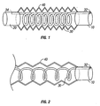
- FIG. 1 an embodiment of the present invention is illustrated, including a multilumen breathing circuit with interacting mutually adjustable length members.
- This embodiment also referred to herein as the F-Coil TM circuit, has optional proximal fitting 10 and an optional distal fitting 20.
- First conduit 30 is a coiled resilient tube having a proximal end 32 and a distal end 34. Proximal end 32 of first conduit 30 is connected to proximal fitting 10 and distal end 34 of first conduit 30 is connected to distal fitting 20.
- proximal fitting 10 may provide a proximal connector for tube 30. End 32 and fitting 10 may vary in diameter, shape and spatial relationship to provide for connection to any standard "F2 TM type" proximal terminal, such as that described in U.S. Patent 5,778,872, to Fukunaga.
- the second or outer tube 40 is flexible and corrugated, and formed of a transparent (or semi-transparent) material.
- Preferred corrugated tubing includes, for example ULTRA-FLEX® , which upon axial extension from its compressed axial conformation, or vice versa, will retain its axial length (e.g., will not rebound; i.e., accordion-like pleated tubing). Further, the ULTRA-FLEX® , when bent, will retain the angle of curvature to which it is bent without substantial reduction in the tube's inner diameter.
- Suitable corrugated tubing for use in the present invention is used in the Ultra-Flex circuit, ULTRA-FLEX® tubing from King Systems Corporation, of Noblesville, IN, U.S.A., or the tubing used in the Isoflex TM circuit sold by Baxter Corporation of Round Lake, IL, USA.
- the tubing may be formed with integral distal and/or proximal fittings, wherein the fittings have relatively thicker or more rigid walls than the tubing, or the tubing can be bonded or welded to appropriately shaped fittings as desired.
- first and second conduits (30, 40) may vary depending on use.
- outer tube 40 or inner tube 30 may be replaced with a suave tube.
- a coiled flexible tube may change its overall axial configuration without altering the cross-sectional shape of the lumen or lumens within it.
- the outer tube 40 ends in an optional distal outer fitting 20, which is designed for ready connection to patient devices, such as an endotracheal tube, laryngeal tube, laryngeal mask or anesthesia mask.
- patient devices such as an endotracheal tube, laryngeal tube, laryngeal mask or anesthesia mask.
- the distal end 34 of the first tube may be directly bonded to the interior of second tube 40.
- the first tube may be directly bonded to the interior of second tube 40 at a series of designated points along the length of tube 40.
- First tube 30 may also be wrapped around the exterior of tube 40, and periodically bonded to the exterior thereof.
- distal fitting 20 is connected to an optional inner distal fitting to which the distal end 34 of first tube 30 may be connected.
- the length of fitting 20 may be extended and the connection point between fitting 20 and the optional distal inner fitting made axially adjustable, wherein a predetermined dead space may be provided.
- second conduit 40 has been axially extended, which causes first conduit 30 to axially extend.
- the length, diameter, number of coils per inch, and resiliency of first conduit 30 is selected to prevent kinking of first conduit 30 upon extension that would block flow therethrough, yet provide for axial retraction or rebound of coil 30 upon axial contraction of outer tube 40, without compromising the performance of the unilimb circuit.
- the resiliency of the coil, or tendency to recoil should not cause disconnection of the proximal end 32 of the inner conduit 30 from proximal fitting 10 when the outer conduit 40 is axially extended to its maximum length, and likewise it should not cause the distal end 34 of inner conduit 30 to axially move with respect to the distal end of tube 40.
- Inner conduit 30 can be manufactured from medical grade plastic, for example, that used to provide for respiratory gas sampling, or such as that used in intravenous fluid devices.
- An axially extensible and collapsible or compressible tube (e.g, accordion-like tubing, coiled tubing, etc.) used as the first tube (which may be an inner or outer tube), and wherein the second, or inner tube or adjacent tube also expands or compresses in a synchronized manner with the first tube is greatly desirable because it promotes safety, as disconnections, obstructions and kinking are diminished. This also enhances rebreathing control and provides greater flexibility and cost effectiveness as manufacturing, storage and shipping become less expensive.
- first tube which may be an inner or outer tube
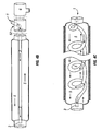
- Two coiled tubes 60 and 62 are in parallel-coiled relationship to form a double coil circuit.
- the tubes may be bonded together at one or more external points, one tube may be formed within the other, or one tube may be divided by a common wall forming two lumens.
- the interaction of the members upon expansion is illustrated in an exploded view, along with their alignment with a proximal fitting 70 and proximal terminal 80 used in a circle system.
- Flow arrows demonstrate the paths of inspiratory gases from the FGF (fresh gas flow) inlet and to the expiratory gas outlet.
- Tubes 60 and 62 are connected at their distal ends to a distal fitting 72 via nipples 74.
- FIGs 5C-D illustrate an alternative embodiment of the double coil illustrated in Figures 5A-B.
- Coiled tubes 600 and 620 are connected to a proximal fitting 700, which connects the respective tubes to proximal terminal 800 used in a circle system.
- tubes 600 and 620 are interlocked by the interaction of their coils, and may optionally be periodically bonded together.
- fittings can be attached on either the inside or outside of the walls of tubes 600 and 620.
- Tubes 600 and 620 are connected at their distal ends to a distal fitting 702 via nipples 704.
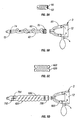
- a first tube 90 is slidably inserted into proximal fitting 92 via sealing fitting 94.
- a second tube 96 is connected at its proximal end to proximal fitting 92, with a portion of tube 96 removed to reveal the first tube 90 inside.
- Tube 96 is axially compressible and extendable, and may be for example made of ULTRA-FLEX® tubing.
- First tube 90 is provided with a smooth walled portion to permit sliding in and out of fitting 92 in response to axial contraction and extension of tube 96.
- the mutually axial interaction of the circuit members may be accomplished by direct connection of the distal end of tube 90 to the distal end of tube 96, via a common distal fitting, or other operative connection techniques and devices.
- Dual coaxial accordion tubes 98 and 100 may be connected at their proximal ends to each other or to a proximal fitting.
- the tubes 98 and 100 may both be ULTRA-FLEX® tubing.
- Spacing flanges or perforated disks 102 may be placed between the inner and outer tubes to optimize flow.
- the mutually axial interaction of the circuit members may be accomplished by direct connection of the distal ends of the tubes to each other, via a common distal fitting, or other operative connection techniques and devices, for example by a spacing flange or disk 102 placed near or at the distal end of tube 98.
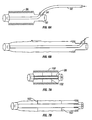
- FIGS 8A-B illustrate the components and operation of a wavy tube sheath in an accordion tube circuit embodiment of the present invention in schematic form.
- a relatively smooth walled tube 106 has a fixed bias to have a wavy contracted shape.
- Tube 106 of resilient material, can straighten when extended and return to its pre-biased contracted shape.
- An outer tube 108 can be extended and contracted simultaneously with tube 106. Spacing flanges or perforated disks may be placed between the inner and outer tubes to optimize flow.
- the mutually axial interaction of the circuit members may be accomplished by direct connection of the distal end of the tubes to each other, via a common distal fitting, or other operative connection techniques and devices. Further, a variety of material can be used.
- tube 108 may be ULTRA-FLEX®
- tube 106 may be a fabric or plastic sheath that can be elastic and radially flexible.
- the axial resiliency (i.e., tendency to recoil or contract) of the inner conduits in the circuits of the present invention is insufficient to dislodge the proximal end thereof from an inspiratory gas inlet when the circuit is fully extended.
- drawing 8B the tendency of tube 106 to rebound to its compressed or relaxed state, illustrated in drawing 8A, should not be sufficient to dislodge the proximal end of tube 106 from proximal fitting 110 when the fitting is held stationary and the conduits 108 and 106 extended.
- tube 106 may be a fabric or plastic sheath that can be radially flexible.
- tube 106 may be a suave tube, and/or tube 108 may be a suave tube.
- the inner or outer tubes of a respiratory conduit in accordance with this embodiment of the present invention may relax or collapse when not in use and expand to required patency on demand. Additional lumens can be added in this and other embodiments.
- a hybrid circuit comprises conventional conduit and at least one flexible plastic sheet (e.g., polyvinyl) that forms a wall defining two or more lumens in the conduit.
- Figures 9A-B illustrate the components and operation of hybrid circuit with a common contractile wall of the present invention in schematic form.
- First and second tubes 116 and 118 share a common outer wall 120 that is axially expandable and contractible, and a common dividing wall 122 that can axially expand and contract with the outer wall.
- This embodiment may be constructed of pleated material such as that used to form ULTRA-FLEX® .
- common dividing wall 122 may be formed of a flexible plastic sheet, which permits the cross-sectional size of the two lumens to accommodate usage conditions.
- the wall when pressure is higher in one lumen than the other, the wall expands into the lower-pressure lumen to make it smaller than the higher-pressure lumen, while the former lumen becomes larger.
- the wall has a maximum radius under respiratory care operating conditions.
- Additional lumens can be included, which either share the common flexible wall, or have diameters that are independent of the diameters of the other lumens.
- This embodiment can be formed by cutting conventional tubing in half, and bonding a flexible plastic sheet in between the two halves, or by extruding elongated hemi-circular shaped portions of plastic, and bonding a flexible plastic sheet between matching tube halves.
- Fig. 10 illustrates the components and operation of another version of the embodiment of Figure 8 in schematic form, in which a second conduit formed of a smooth plastic lamina, e.g., a Suave TM tube, 140 envelopes an inner tube or first conduit 150 comprised of a corrugated tube. While the outer or second conduit 140 can collapse when not being used, the inner conduit 150 maintains its diameter during respiratory care operating conditions and during ambient and non-use conditions.
- a second conduit formed of a smooth plastic lamina e.g., a Suave TM tube
- the respiratory conduit 141 includes a proximal fitting 142 that is bonded to proximal ends of tubes 140 and 150.
- the proximal fitting facilitates connection to a corresponding proximal terminal.
- a distal fitting 151 is connected to the distal ends of tubes 140 and 150.
- the distal end of tube 150 is bonded to flanges 152.
- Radial flanges 152 are not solid annular rings, but have gaps 153 to permit flow of gases from common zone 154 into tube 140. While tube 140 may collapse under ambient, non-use conditions, in use, tube 140 may be expanded to its maximum radius and volume during expiration as well as during inspiration (depending on whether it is used for inspiration or expiration) provided there is a sufficient flow rate of gases; there is no or minimal compliance at maximum radius.
- Axial flanges 155 connect to radial flanges 152 and grip the distal end of inner tube 150.
- Tube 150 may be bonded to radial flanges. Axial extension of radial flanges 152 and/or axial flanges 155 can provide a greater fixed dead space. As noted in other embodiments, the distal fitting, such as distal fitting 151, can be modified to provide for a sliding connection between the distal fitting main housing and the connector to the inner conduit, wherein the dead space may be adjusted to a desired volume.
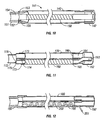
- Fig. 11 illustrates the components and operation of a unilimb respiratory conduit in schematic form, in which a first flexible tube 160 is a conventional flexible tube that maintains a fixed diameter at ambient conditions and over respiratory therapy operating conditions, while the second tube 170 is a non-conventional plastic tube that may radially collapse when patency is not required.
- tube 170 is a suave flexible tube.
- a new proximal fitting 162 is illustrated, in which a coaxial flow is diverted into two independent lumens 163 and 164 that have two independent non-interfering ports 165 and 166, i.e., independent, non-interfering ports are ports that can be individually accessed without blocking or interfering with access to another port or requiring the disconnection of one port.
- Distal fitting 172 has axial walls 173 and 174 to which the distal ends of tubes 160 and 170 may be bonded. Extension of axial walls 173 and 174 permits for dead space adjustment. Connecting flange 175 has a gap 176 to provide for patency, while holding wall 174 in spaced relationship with wall 173.
- Fig. 12 illustrates the components and operation in schematic form of a unilimb respiratory conduit formed of two non-conventional tubes or conduits 180 and 190, e.g., suave tubes, joined at their distal ends by distal fitting 182 and at their proximal ends by proximal fitting 192.
- Tube 190 includes a coiled tube 200, which is more radially rigid than the tube in which it is contained so as to assist in maintaining patency of its host tube.
- Tube 200 may be used for gas sampling or other purposes.
- tube 190 may provide inspiratory gases.
- Tube 190 is held patent by the coiled tube 200, and tubes 180 and 190 are of fixed axial length. The recoiling of tube 200 causes tubes 180 and 190 to collapse axially.
- tube 200 includes a wire of metal or plastic that maintains whatever length it is extended to rather than being axially elastic as in other embodiments.
- the inner wall of tube 190 is optionally bonded at periodic intervals to tube 200 so as to provide for even folding and extension of the fabric forming tube 190.
- tube 200 is a solid wire.
- Fitting 192 provides for rapid connection of the respiratory conduit to a corresponding multilumen proximal terminal. While outlet 201 of tube 200 is shown passing through the wall of fitting 192, fitting 192 may have an extra lumen for connecting tube 200 to a corresponding inlet or outlet.
- breathing circuits also referred to as multilumen unilimb respiratory conduits, which axially and/or radially expand or contract.
- the breathing circuit does not need to expand or contract axially.
- An embodiment may comprise one fixed length conduit that is a conventional corrugated tube or a smooth resilient tube having a pipe-like configuration or an ULTRA-FLEX® tube, and the second conduit can be a non-conventional conduit.
- the respiratory conduit can be of fixed length, and one or more of the tubes in it may radially expand and contract.
- a breathing circuit or unilimb respiratory conduit of the present invention can be readily connected to a respirator or ventilator, or to an anesthesia machine either via the proximal fitting of the respiratory conduits or via a proximal terminal, such as the one described in US Patent 6,003,511.
- a proximal terminal such as the one described in US Patent 6,003,511.
- respiratory conduits in accordance with the present invention can be provided for quick and safe connection to a variety of respiratory devices, including but not limited to anesthesia machines and ventilator machines. This can be done directly or via a filter.
- a breathing circuit of the present invention can be connected to a single filter or a multilumen filter, or manufactured integrally with a monolumen or multilumen filter.
- the proximal end of the filter housing can be configured for quick and safe connection to a proximal terminal of a machine, and the distal end of the filter housing can match the configuration of the proximal end of the respiratory conduit.
- Respiratory conduits of the present invention can also be used to ventilate patients during transport, or be connected to a gas source (e.g., oxygen source in the post-anesthesia care setting, emergency room, etc.).
- a gas source e.g., oxygen source in the post-anesthesia care setting, emergency room, etc.
- the breathing circuit of the present invention is a multi-purpose breathing circuit.
- the same breathing circuit of the present invention can be utilized to provide oxygenation during transportation of a patient, for example to the PACU or other location. After the patient is transported for example from the operating room to the PACU, the same breathing circuit can be utilized to oxygenate the patient in the PACU, without the need to utilize an additional oxygen supply device, such as a nasal cannula or clear oxygen mask provided with an oxygen tube or a T piece set.
- drawing 3A illustrates a schematic diagram of a Mapleson D system, in which the fresh gas flow (“FGF") 1 is provided via fresh gas delivery tube 2 (shown in schematic form only) to a distal fitting 3.
- FGF fresh gas flow
- FIG. 3A illustrates a schematic diagram of a Mapleson D system, in which the fresh gas flow (“FGF") 1 is provided via fresh gas delivery tube 2 (shown in schematic form only) to a distal fitting 3.
- FGF fresh gas flow
- Drawing 3B illustrates a Bain circuit used with a Mapleson D system.
- a key feature of the Bain is that the fresh gas tube 2 is inserted in the proximal terminal at the proximal end of the circuit and the tube extended through breathing tube 5 to have its distal end 3 at the distal end of the circuit.
- Drawing 3C illustrates a circle CO 2 absorption system, which has a CO 2 absorber 12, check valves (i.e., unidirectional valves) 4 and 9, as well as inspiratory conduit 5 and expiratory conduit 8 that meet at distal fitting 6.
- gas to lungs 7 flows simultaneously from fresh gas flow source 1 and bag 10 via flow paths c and d in the key below Fig. 3C as follows: (1 ⁇ 2 ⁇ 3 ⁇ 4 ⁇ 5 ⁇ 6 ⁇ 7) + (10 ⁇ 12 ⁇ 4 ⁇ 5 ⁇ 6 ⁇ 7).
- gases flow from lungs 7 to waste gas outlet 11 via flow paths c' and d' as follows: (1 ⁇ 2 ⁇ 3 ⁇ 12) + (7 ⁇ 6 ⁇ 8 ⁇ 9 ⁇ 10 ⁇ 11.
- Drawing 3D illustrates a circle CO 2 absorption system, which uses either a Universal F® or Universal F2® circuit using an F2 TM -type proximal terminal.
- Inspiratory conduit 5 is coaxial within expiratory conduit 8 distal of the proximal terminal.
- drawing 4A illustrates an assisted ventilation system of the present invention utilizing an embodiment of a new breathing circuit of the present invention.
- Fresh gas flow from a source 1 passes via flow diverter 70 through fresh gas delivery tube 2 (shown in schematic form only).
- Flow diverter 70 is optional as it is provided for modifying a circle system having a fresh gas input port in the scrubber circuit (generally near or at the CO 2 absorber). The flow diverter closes off the fresh gas input port on top of CO 2 absorber 12 so that fresh gases can be directly fed to the distal end 3 of the breathing conduit (i.e. FGF bypasses the scrubber module so it is not mixed with scrubbed gases).
- tube 2 is, as with a Bain, rigidly bonded to proximal fitting 50, and fresh gases are delivered directly to the distal end 3 of the breathing circuit, which continuously feed the common inspiratory/expiratory conduit 5, also referred to as a rebreathing tube.
- the dimensions of conduit 5 can be altered so that the tube volume and the concentration of its contents are altered so that the inspired concentration of gases can be adjusted for each patient, and rebreathing can be controlled.
- tube 5 may be an ULTRA-FLEX® tube. Control can be achieved by adjusting the dimensions of tube 5, for example by axially adjusting the length of tube 5 (titration of tube volumes and contents in response to inspired and/or end-tidal gas concentration data provided by the monitoring equipment).
- the fresh gases delivered directly from the anesthesia machine are not mixed or diluted at the machine/scrubber circuit end. Because the fresh gas flow is delivered close to the patient, the inspired anesthetic concentrations are almost equal to the delivered concentrations. Thus, the anesthetist can rely on the anesthetic concentrations reported by the flow meter and the vaporizer as indicative of the inspired concentrations.
- the expired gases are not all disposed of but are reused as "refreshed gas," as expired gases pass through a scrubber module for recirculation.
- This new "F system” provides a surprising improvement in the control and quality of respiratory and anesthetic ventilation while avoiding waste of anesthetic gases.
- a coiled fresh gas tube is used, upon contraction of tube 5, tube 2 coils to contract, as can be seen in Figure 4 C.
- the fresh gas tube 2 can have other shapes and can be arranged to be an inner or outer tube with respect to tube 5. If tube 2 is smooth-walled, it can slide in and out of a fitting as shown in Fig. 6.
- the volume of tube 5 during use is adjusted to be larger than the tidal volume (V T ) to minimize mixing of the fresh gases with the "scrubbed gases". This allows optimal utilization of the fresh gases (anesthetic agents) as well as 02 and CO2 rebreathing control.
- the length of the rebreathing tube may be variable for multiple usages.
- the same breathing system may be universally used, in an operating room, ICU, emergency room, respiratory care ward, in adult and pediatric cases, etc.
- Drawing 4B illustrates a proximal terminal 52 in schematic form that may be separately detached and connected to breathing conduit 5 and fresh gas tube 2.
- An additional proximal terminal 6 is also shown in schematic form.
- Terminal 6 can be an F2® type or Y adaptor.
- the system components also preferably includes a reservoir bag or ventilator device 10, waste gas outlet 11, which may be attached to a scavenger, CO 2 absorber 12, check valves 40 and 90, inspiratory conduit 5', expiratory conduit 8', and a proximal terminal 6 that connects to proximal fitting 50.
- gas to lungs 4 flows simultaneously from fresh gas flow source 1 and bag/ventilator 10 as follows: (1 ⁇ 2 ⁇ 3 ⁇ 4) + (10 ⁇ 12 ⁇ 40 ⁇ 5' ⁇ 6 ⁇ 5 ⁇ 3 ⁇ 4).
- gases flow from lungs 4 to waste gas outlet 11 as follows: (1 ⁇ 2 ⁇ 3 ⁇ 5) + (4 ⁇ 3 ⁇ 5 ⁇ 6 ⁇ 8' ⁇ 90 ⁇ 10 ⁇ 11).
- a new ventilation and anesthesia system comprising a recirculation module, a rebreathing tube operatively connected at its proximal end opening to the recirculation module for providing expired gases to and receiving gases from the recirculation module, and a distal input for fresh gases, wherein the distal input is located in the distal portion of the rebreathing tube or in a distal fitting operatively connected to the distal end of the rebreathing tube.
- the recirculation module preferably includes a scrubbing circuit, which may include at least two unidirectional valves, an expiratory input conduit, CO2 absorber, exhaust vent, scrubbed gas output conduit, and squeeze bag and/or ventilator.
- a filter device can be detachably connected at the proximal end of the rebreathing conduit 5; the filter device may also be integrally formed with conduit 5.
- a preferred embodiment of this new system is referred to as an F3 TM COMBO system.
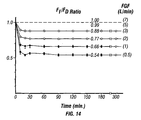
- the following hypotheses were tested: a) The inspired and the delivered fresh gas concentration (FI/FD) ratio is dependent on the fresh gas flow (FGF) over time; and b) Using the F3 TM COMBO system the F I /F D ratio can be improved at low flows.
- FI/FD inspired and the delivered fresh gas concentration
- FGF fresh gas flow
- ASA class I ASA class I adult patients undergoing elective surgery were included in the studies.
- the studies were conducted using standard methods of anesthesia: Anesthesia was induced with thiopental and endotracheal intubation was facilitated with 1 mg/kg succinylcholine. Anesthesia was initially maintained with high flow (5 L/min) of 3/2 N 2 O-O 2 mixture and 1.5% isoflurane as per vaporizer setting using the standard anesthesia circle system with CO 2 absorption. The patient's lungs were mechanically ventilated using the traditional mode of intermittent positive pressure ventilation with a tidal volume of 10 ml/kg, ventilation frequency (10-12 breaths/min) and inspiratory/expiratory ratio (1:2).
- Fraction of delivered (F D ), inspired (FI) and end-tidal (FET) anesthetic gas concentrations were continuously monitored by mass spectrometry (Medical Gas Analyzer 100; Perkin-Elmer, Pomona, CA).
- the anesthetist With the present F3 COMBO TM system, the anesthetist will be able to better control the inspired concentration of anesthetic gases in a more accurate and predictable manner. Therefore, even in the absence of expensive multi-gas monitoring equipment, a safe and reliable low flow anesthesia can be achieved. Also, recovery from anesthesia can be accelerated at the end of surgery and anesthesia. This can be accomplished by providing high flows of oxygen directly at the distal end so that the residual anesthetic in the lungs and the breathing circuit will be washed out very quickly. Quick recovery from anesthesia can save anesthesia recovery time and money.
- the F3 COMBO TM circuit and/or methods for utilizing same can conserve anesthetic gases as well as oxygen, while minimizing pollution and health hazards, and thus improve breathing/anesthesia system efficiency. This will result in an overall lower health care costs, while optimizing patient health care.
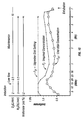
- Fig. 15 shows the changes of continuous and simultaneous monitoring of the delivered (F D ), inspired (F I ) and end-tidal (F ET ) gas concentration during low flow anesthesia of 1 L/min with a constant isoflurane vaporizer setting of 1.2% over time. Notice the significant difference between the F D gas concentration (i.e., vaporizer setting concentration) and the F I and F ET gas concentration.
- F D gas concentration i.e., vaporizer setting concentration
- the present invention provides a method of providing assisted ventilation or anesthesia wherein fresh gases are provided at low flow, for example a volume of about 1 liter per minute (flows considered low range from about 0.5 to less than 5 L/min, or less than 3 L/min in preferred embodiments), and the F I / F D concentration ratio can be maintained at a desired level, for example above about 0.80 or higher, by adjusting the volume of the rebreathing tube proximal of the fresh gas input.
- fresh gas flows from about 1 to about 3 L/min are used, and more preferably from about 1 to about 2 L/min.
- the present invention permits use of smaller respiratory conduits, and disposable components therefore.
- multiple circuits must be used for a single day's surgeries. This requires that the circuits be stored in or near the operating room. To prepare for each surgery, a new circuit is removed from a sterile package, and the bag is disposed of. If care is not taken in opening the bag, the circuit can be damaged.
- a dispenser box 200 is illustrated. Shown in block diagram are respiratory conduits 210, optionally sandwiched between thin protective plastic sheets 212. Preferably, the respiratory conduits 210 are not individually wrapped.
- box 200 includes a line of perforations 214 on its face and top to permit tearing removal or rotating or pivoting elevation of a portion of the box.
- a sealing tape 216 can be provided over perforations 214 to reduce the chance of accidental opening or tampering.
- Boxes of varying quantities can be provided, for example, 4, 6, 8, 10, 12, 15, 24 or more than 100 respiratory conduits.
- the box flap may close under gravity or seal between uses. Loading of such a dispenser box eliminates the need for sealing individual disposal circuit components in separate bags, as well as reduces the time to open and remove bag contents. The dispenser box also reduces the amount of waste generated as less material is disposed of than when individual sealed bags are used.
- the respiratory conduits are essentially cylindrical in their cross-sectional shape.
- the dispenser box may have a thickness and length sufficient for one respiratory conduit in its compressed form, and a height proportional to the number of conduits therein.
- the perforations for the box flap may extend the length of one side of the box, and box incrementally opened at the perforation to access each conduit in order.
- multilumen conduits of the present invention come in a variety of forms, and can be compressed into relatively small volumes for shipping and storage. Hence, a plurality of such conduits can fit nicely into the dispensers described above.
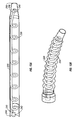
- a respiratory conduit is shown in expanded form (a) and in compressed form (b).
- An outer or first conduit 220 is a suave tube
- the inner conduit 230 is a coiled tube wherein the coiled tube lumen has a relatively rigid cross-sectional shape.
- Proximal fitting 240 is coaxial, with the distal end of coiled tube 230 being bonded to an inner pipe 242 or being integral therewith, although other variations are possible.
- a rigid inner pipe and rigid outer pipe are held together by rigid spacing means to form a proximal fitting to which inner and outer conduits can be connected.
- Inner pipe 242 can be integrally formed with rigid coil 230 in one step.
- inner pipe 242, integrally formed to coil 230 can be bonded to an outer pipe, such as pipe 244, with appropriate spacing means.
- a suave tube can then be bonded to outer pipe 244.
- a single distal fitting 246, with an inner member 248 and an outer member 250 can be bonded to the corresponding tubes prior to bonding of the suave tube to the proximal fitting.
- the distal fitting 246 can also be constructed in a series of steps as it is connected to the tubes.
- inner member 246 can be integrally formed to the distal end of tube 230 when the proximal end of tube 230 is bonded to inner pipe 242.
- Various combinations of construction steps are possible.
- F3 TM circuits described herein are not limited to a unilimb tubing arrangements, but can also use dual limb arrangements in which at least one tube is a suave or coiled tube, which can lead to significant reduced costs in manufacturing, shipping and storage.
- conduits in the circuit may be of different sizes from one another, and more than two lumens may be present.
- larger or smaller diameter conduits may be used, and both circle circuit and Mapleson type circuits may be constructed.
Landscapes
- Health & Medical Sciences (AREA)
- Anesthesiology (AREA)
- Pulmonology (AREA)
- General Health & Medical Sciences (AREA)
- Veterinary Medicine (AREA)
- Biomedical Technology (AREA)
- Heart & Thoracic Surgery (AREA)
- Hematology (AREA)
- Life Sciences & Earth Sciences (AREA)
- Animal Behavior & Ethology (AREA)
- Emergency Medicine (AREA)
- Public Health (AREA)
- Engineering & Computer Science (AREA)
- Measurement Of The Respiration, Hearing Ability, Form, And Blood Characteristics Of Living Organisms (AREA)
- Respiratory Apparatuses And Protective Means (AREA)
- Pharmaceuticals Containing Other Organic And Inorganic Compounds (AREA)
- Medicines Containing Plant Substances (AREA)
- Medicines Containing Material From Animals Or Micro-Organisms (AREA)
- Electrotherapy Devices (AREA)
- Acyclic And Carbocyclic Compounds In Medicinal Compositions (AREA)
- Infusion, Injection, And Reservoir Apparatuses (AREA)
Claims (21)
- Multiluminaler, eingliedriger Atemkreislauf, aufweisend erste (30) und zweite Röhren (40), von denen jede der Röhren ein proximales (10) und ein distales Ende (20) besitzt, wobei das proximale Ende der ersten Röhre operativ mit einem Einlaß für respiratorische Gasc verbunden sein kann, und die zweite Röhre operativ mit einem Auslaß für respiratorische Gase verbunden sein kann, und das distale Ende für eine direkte Verbindung mit einer Patientenluftwegsvorrichtung, und eine axiale Streckung oder Verkürzung der zweiten Röhre eine äquivalente axiale Streckung oder Verkürzung der ersten Röhre verurcacht,
wobei infolge axialer Streckung der zweiten Röhre aus einer ersten verkürzten axialen Gestalt zu einer zweiten gestreckten axialen Gestalt oder umgekehrt , die zweite Röhre so gebildet ist, daß sie die zweite Gestalt beibehält, und die erste Röhre so aufgebaut ist, daß sie sich in der Länge mit der äquivalenten axialen Streckung oder Verkürzung der zweiten Röhre streckt oder verkürzt,
und wobei die zweite Röhre einen Ziehharmonika-ähnlich gefalteten Schlauch aufweist, der so konfiguriert ist daß er seine axiale Länge infolge axialer Streckung aus seinem verkürzten axialen Zustand beibehält und der so konfiguriert ist, daß der Krümmungswinkel beibehalten wird, wenn er ohne wesentliche Reduzierung des Schlauchinnendurchmessers gebogen wird. - Kreislauf gemäß Anspruch 1. wobei die erste Röhre in der zweiten Röhre enthalten ist.
- Kreislauf gemäß einem der Ansprüche 1 oder 2, wobei die erste und zweite Röhre ein gemeinsames distales Anschlußstück (20) an ihren distalen Enden besitzen.
- Kreislauf gemäß Anspruch 3, wobei das distale Anschlußstück eine steife beabstandete oder direkte Verbindung des distalen Endes der ersten Röhre mit dem distalen Ende der zweiten Röhre aufweist.
- Kreislauf gemäß einem der vorhergehenden Ansprüche, wobei die erste und zweite Röhre ein gemeinsames proximales Verbindungs- oder Anschlußstück (10) an ihren proximalen Enden, besitzen.
- Kreislauf gemäß einem der vorhergehenden Ansprüche, wobei die erste Röhre einen Ziehharmonika-ähnlich gefalteten Schlauch (98) aufweist, der seine axiale Länge infolge eines axialen Streckens aus seinem verkürzten axialen Zustand beibehalten wird, und der den Krümmungswinkel beibehalten wird, wenn er gebogen, wird, ohne wesentliche Reduzierung des Schlauchinnendurchmessers.
- Kreislauf gemäß einem der Ansprüche 1 bis 5, wobei die erste Röhre einen spiralförmigen Schlauch (30) aufweist.
- Kreislauf gemäß einem der Ansprüche 1 bis 5, wobei wenigstens eine Röhre radial zusammenfallen kann, wenn sie nicht gebraucht wird.
- Kreislauf gemäß Anspruch 8, wobei die Röhren am distalen Ende durch ein distales Anschlußstück verbunden sind, und wenigstens ein Abschnitt der Röhren wesentlich voneinander beabstandet ist.
- Kreislauf gemäß Anspruch 8 oder 9, wobei die Röhre, die radial zusammenfallen kann, eine Nachgiebigkeit von weniger als 20% besitzt, wenn sie bei Drücken aufgeblasen wird, die beim Vorsehen einer unterstützten Ventilation und/oder Anästhesie an Menschen oder anderen Säugetieren auftreten.
- Kreislauf gemäß Anspruch 10, wobei die Röhre, die radial zusammenfallen kann, eine Nachgiebigkeit von weniger als 10% besitzt, wenn sie bei Drücken aufgeblasen wird, die beim Vorsehen einer unterstützten Ventilation und/oder einer Anästhesie an Menschen und anderen Säugetieren auftreten.
- Kreislauf gemäß einem der Ansprüche 8 bis 11, wobei die Röhre, die radial zusammenfallen kann, eine minimale Querschnittsfläche besitzt, wenn sie vollständig aufgeblasen ist, und zusammenfallen kann, wenn sie nicht gebraucht wird, so daß die zusammengefallene Querschnittsfläche der minimalen Querschnittsfläche im vollständig aufgeblasenen Zustand weniger als 90% von der aufgeblasenen Querschnittsfläche besitzt.
- Kreislauf gemäß Anspruch 12, wobei die Röhre, die radial zusammenfallen kann, eine minimale Querschnittsfläche besitzt, wenn sie vollständig aufgeblasen ist, und zusammenfallen kann, wenn sie nicht gebraucht wird, so daß die zusammengefallene Querschnittsfläche der minimalen Querschnittsfläche im vollständig aufgeblasenen zustand weniger als 10% von der aufgeblasenen Querschnittsfläche besitzt.
- Kreislauf gemäß einem der vorhergehenden Ansprüche, des weiteren aufweisend einen Filter.
- Kreislauf gemäß Anspruch 14, wobei der Kreislauf ein distales Ende und ein proximales Ende besitze und der Filter am proximalen Ende der Röhre angeordnet ist.
- Kreislauf gemäß einem der Ansprüche 1 oder 3 bis 5, wobei die erste Röhre und die zweite Röhre durch eine streckbare und verkürzbare gemeinsame Trennwand (122) getrennt sind.
- Kreislauf gemäß einem der vorhergehenden Ansprüche, wobei der Luftströmungswiderstand der ersten und zweiten Röhren ausreichend niedrig ist, um die Anforderungen für eine spontane Ventilation oder eine unterstützte Ventilation zu erfüllen.
- Kreislauf gemäß einem der vorhergehenden Ansprüche, wobei die axiale Streckung oder verkürzung das Volumen von wenigstens einer der ersten oder zweiten Röhren einstellen wird.
- Atemkreislauf gemäß einem der vorhergehenden Ansprüche, wobei der Kreislauf ein kreisförmiger Kreislauf oder ein Kreislauf vom Typ Mapleson ist.
- Kreislauf gemäß einem der vorhergehenden Ansprüche, wobei das distale Ende der ersten Röhre einen Anschluß zur Aufnahme der ersten Röhre enthält, wobei die Achse des Anschlusses radial von der Achse des distalen Endes des gemeinsamen distalen Anschlußstücks versetzt ist.
- Kreislauf gemäß Anspruch 18, wobei die ersten oder zweiten Röhren inspiratorische Röhren sind und eine Gasströmung zu jeder Zeit während der spontanen Ventilation einschließlich unter einem Unterdruck Zulassen.
Priority Applications (1)
| Application Number | Priority Date | Filing Date | Title |
|---|---|---|---|
| EP05077222A EP1621224A3 (de) | 2001-09-24 | 2002-09-24 | Beatmungskreislauf mit anpassbaren Volumen und Länge |
Applications Claiming Priority (7)
| Application Number | Priority Date | Filing Date | Title |
|---|---|---|---|
| US32455401P | 2001-09-24 | 2001-09-24 | |
| US324554P | 2001-09-24 | ||
| US34020601P | 2001-12-12 | 2001-12-12 | |
| US340206P | 2001-12-12 | ||
| PCT/US2002/030537 WO2003026721A2 (en) | 2001-09-24 | 2002-09-24 | Breathing circuits having unconventional respiratory conduits and systems and methods for optimising utilisation of fresh gases |
| US10/254,700 US6874500B2 (en) | 2001-09-24 | 2002-09-24 | Breathing circuits having unconventional respiratory conduits and systems and methods for optimizing utilization of fresh gases |
| US254700 | 2002-09-24 |
Related Child Applications (1)
| Application Number | Title | Priority Date | Filing Date |
|---|---|---|---|
| EP05077222A Division EP1621224A3 (de) | 2001-09-24 | 2002-09-24 | Beatmungskreislauf mit anpassbaren Volumen und Länge |
Publications (3)
| Publication Number | Publication Date |
|---|---|
| EP1432475A2 EP1432475A2 (de) | 2004-06-30 |
| EP1432475A4 EP1432475A4 (de) | 2005-01-12 |
| EP1432475B1 true EP1432475B1 (de) | 2006-06-07 |
Family
ID=27400799
Family Applications (1)
| Application Number | Title | Priority Date | Filing Date |
|---|---|---|---|
| EP02763738A Expired - Lifetime EP1432475B1 (de) | 2001-09-24 | 2002-09-24 | Atemkreisläufe mit unkonventionellen atemleitungen und systeme und verfahren zur optimierung der verwendung von frischgasen |
Country Status (15)
| Country | Link |
|---|---|
| US (2) | US6874500B2 (de) |
| EP (1) | EP1432475B1 (de) |
| JP (1) | JP4348182B2 (de) |
| CN (1) | CN100512910C (de) |
| AT (1) | ATE328629T1 (de) |
| AU (1) | AU2002327732B2 (de) |
| BR (1) | BR0212774B1 (de) |
| CA (1) | CA2460773C (de) |
| DE (1) | DE60212158T2 (de) |
| ES (1) | ES2266559T3 (de) |
| HK (1) | HK1073807A1 (de) |
| MX (1) | MXPA04002687A (de) |
| NZ (1) | NZ532166A (de) |
| PT (1) | PT1432475E (de) |
| WO (1) | WO2003026721A2 (de) |
Cited By (2)
| Publication number | Priority date | Publication date | Assignee | Title |
|---|---|---|---|---|
| RU2552501C1 (ru) * | 2014-06-10 | 2015-06-10 | Борис Владимирович Смоляров | Генератор потока дыхательного газа |
| US11826513B2 (en) | 2015-10-24 | 2023-11-28 | Ambu A/S | Breathing circuit systems and devices |
Families Citing this family (78)
| Publication number | Priority date | Publication date | Assignee | Title |
|---|---|---|---|---|
| JP4348182B2 (ja) | 2001-09-24 | 2009-10-21 | エフ−コンセプツ エルエルシー | 通常とは異なる呼吸導管を有する呼吸回路、及び新鮮ガスを最適に利用するシステム及び装置 |
| US7717109B2 (en) | 2001-09-24 | 2010-05-18 | F-Concepts Llc | Breathing systems with post-inspiratory valve fresh gas flow input, components for implementing same, and methods of use |
| US6953465B2 (en) * | 2002-03-25 | 2005-10-11 | Concentric Medical, Inc. | Containers and methods for delivering vaso-occluding filaments and particles |
| WO2004052463A1 (en) * | 2002-12-12 | 2004-06-24 | Oleg Bassovitch | Breathing apparatus for hypoxic pre-acclimatization and training |
| GB0302196D0 (en) * | 2003-01-30 | 2003-03-05 | Boc Group Plc | Medical apparatus |
| EP1610852B1 (de) * | 2003-02-18 | 2018-12-05 | Joseph Fisher | Beatmungskreislauf zur erleichterung der messung des herzzeitvolumens während gesteuerter und spontaner beatmung |
| US7007691B2 (en) * | 2003-05-13 | 2006-03-07 | Roger Daugherty | Apparatus and method for humidification of inspired gases |
| US7152597B2 (en) * | 2003-09-25 | 2006-12-26 | Datex-Ohmeda, Inc. | Breathing circuit adapter |
| WO2005033002A2 (en) | 2003-09-30 | 2005-04-14 | The Research Foundation Of State University Of New York | Device and method of partially separating gas |
| US7178521B2 (en) * | 2004-01-09 | 2007-02-20 | King Systems Corporation | Adjustable length breathing circuit |
| US7870857B2 (en) * | 2005-05-23 | 2011-01-18 | Aeon Research And Technology, Inc. | Patient interface assemblies for use in ventilator systems to deliver medication to a patient |
| US9211398B2 (en) | 2005-05-23 | 2015-12-15 | Resmed Limited | Connector system for an apparatus that delivers breathable gas to a patient |
| WO2007019624A1 (en) * | 2005-08-15 | 2007-02-22 | Resmed Ltd | Cpap systems |
| WO2008011683A1 (en) | 2006-07-28 | 2008-01-31 | Resmed Ltd | Delivery of respiratory therapy |
| CN103252008B (zh) | 2006-07-28 | 2017-04-26 | 瑞思迈有限公司 | 呼吸治疗的传送系统 |
| EP2481434B1 (de) | 2006-12-15 | 2016-04-13 | ResMed Ltd. | Verabreichung einer Atemtherapie |
| FR2914192B1 (fr) * | 2007-04-02 | 2010-03-26 | Georges Boussignac | Sonde respiratoire. |
| US7900633B2 (en) * | 2007-04-12 | 2011-03-08 | Sinha Shailendra K | Breathing circuit |
| AU2008221506B2 (en) | 2007-09-20 | 2011-01-20 | ResMed Pty Ltd | Retractable Tube for CPAP |
| CN101932355B (zh) * | 2007-11-12 | 2015-07-22 | 马奎特紧急护理公司 | 从麻醉呼吸机到患者的多种麻醉剂的输送的调节 |
| CN101896216B (zh) * | 2007-11-14 | 2013-07-31 | 马奎特紧急护理公司 | 带有可变患者回路容量的患者盒 |
| DE102008022663B4 (de) | 2008-05-07 | 2012-10-31 | Schauenburg Hose Technology Gmbh | Stretch-Schlauch |
| US9505164B2 (en) | 2009-12-30 | 2016-11-29 | Schauenburg Technology Se | Tapered helically reinforced hose and its manufacture |
| CN102015000B (zh) * | 2008-05-07 | 2014-05-14 | 皇家飞利浦电子股份有限公司 | 排气组件 |
| DE102008022924A1 (de) * | 2008-05-09 | 2009-11-12 | Siemens Aktiengesellschaft | Vorrichtung und Verfahren für einen medizinischen Eingriff |
| US8539953B2 (en) | 2008-11-19 | 2013-09-24 | John E. Moenning, Jr. | Combination anesthesia and scavenger surgical mask |
| DE102009013396B3 (de) * | 2009-03-16 | 2010-08-05 | Dräger Medical AG & Co. KG | Vorrichtung und Verfahren zur Steuerung der Sauerstoffdosierung eines Beatmungsgerätes |
| US9964238B2 (en) | 2009-01-15 | 2018-05-08 | Globalmed, Inc. | Stretch hose and hose production method |
| US8267081B2 (en) | 2009-02-20 | 2012-09-18 | Baxter International Inc. | Inhaled anesthetic agent therapy and delivery system |
| US8460272B2 (en) * | 2009-05-22 | 2013-06-11 | Susan Leeds Kudo | Method and apparatus for extensible intravenous drip line |
| US9675170B2 (en) * | 2009-11-28 | 2017-06-13 | Linak A/S | Telescopic column, preferably for furniture |
| GB201006480D0 (en) | 2010-04-19 | 2010-06-02 | Intersurgical Ag | Improvements relating to respiratory apparatus |
| US8555887B2 (en) | 2010-04-30 | 2013-10-15 | Covidien Lp | Tracheal tube with dividing membrane |
| CN103079621B (zh) * | 2010-06-30 | 2015-09-16 | 圣米高医院 | 用于通过气管内贯流的与患者同步的通气辅助的方法和系统 |
| US20120060836A1 (en) * | 2010-09-10 | 2012-03-15 | Michael El-Shammaa | Patient circuit for improved support delivery |
| US9067037B2 (en) | 2010-09-10 | 2015-06-30 | Carefusion 207, Inc | Adjusting a position of a heating wire within a breathing circuit |
| CA2834635C (en) | 2011-04-29 | 2019-07-30 | Robert Tero | Nasal interface device |
| CN113730752A (zh) | 2011-06-03 | 2021-12-03 | 费雪派克医疗保健有限公司 | 医用管和制造方法 |
| EP2755710B1 (de) | 2011-09-13 | 2018-05-23 | ResMed Limited | Lüftunganordnung für atemmaske |
| US9032954B2 (en) * | 2011-10-01 | 2015-05-19 | Jerome Bernstein | Anesthesia machine CO2 absorber bypass |
| JP6181658B2 (ja) * | 2011-11-08 | 2017-08-16 | レスメド・リミテッドResMed Limited | 電気刺激呼吸補助コンポーネント |
| DE102011055439A1 (de) * | 2011-11-17 | 2013-05-23 | Hamilton Bonaduz Ag | Schlauch für ein Beatmungssystem |
| US9498592B2 (en) | 2012-01-23 | 2016-11-22 | Aeon Research And Technology, Inc. | Modular pulmonary treatment system |
| JP6403121B2 (ja) | 2012-03-15 | 2018-10-10 | フィッシャー アンド ペイケル ヘルスケア リミテッド | 呼吸ガス加湿システム |
| IN2014MN02333A (de) | 2012-04-27 | 2015-08-14 | Fisher & Paykel Healthcare Ltd | |
| US10076619B2 (en) | 2012-09-11 | 2018-09-18 | Resmed Limited | Vent arrangement for respiratory mask |
| CN107441602B (zh) | 2012-11-14 | 2021-09-03 | 费雪派克医疗保健有限公司 | 用于呼吸回路的分区加热 |
| US9795756B2 (en) | 2012-12-04 | 2017-10-24 | Mallinckrodt Hospital Products IP Limited | Cannula for minimizing dilution of dosing during nitric oxide delivery |
| CN113577492A (zh) | 2012-12-04 | 2021-11-02 | 费雪派克医疗保健有限公司 | 医用管以及其制造方法 |
| EP3636306B1 (de) | 2012-12-04 | 2024-01-31 | Mallinckrodt Hospital Products IP Limited | Kanüle zur minimierung der verdünnung eines dosierung während der stickoxidverabreichung |
| WO2014165116A1 (en) * | 2013-03-13 | 2014-10-09 | Teleflex Medical Incorporated | Multi-lumen breathing circuit including a flexible printed circuit board assembly |
| NZ760660A (en) | 2013-03-14 | 2021-07-30 | ResMed Pty Ltd | Vent arrangement for a respiratory device |
| US10328222B2 (en) | 2013-03-14 | 2019-06-25 | ResMed Pty Ltd | Vent device for use with a respiratory device |
| CN105188821B (zh) * | 2013-03-15 | 2020-01-07 | 费雪派克医疗保健有限公司 | 用于医疗回路的组件 |
| WO2015038870A1 (en) | 2013-09-12 | 2015-03-19 | Mayo Foundation For Medical Education And Research | Insulated endotracheal devices and systems for transpulmonary thermal transfer |
| WO2015038013A1 (en) | 2013-09-13 | 2015-03-19 | Fisher And Paykel Healthcare Limited | Connections for humidifcation system |
| WO2015060731A1 (en) | 2013-10-24 | 2015-04-30 | Fisher & Paykel Healthcare Limited | Delivery of respiratory gases |
| CN110947069A (zh) | 2013-12-20 | 2020-04-03 | 费雪派克医疗保健有限公司 | 加湿系统连接 |
| WO2015119515A1 (en) | 2014-02-07 | 2015-08-13 | Fisher & Paykel Healthcare Limited | Respiratory humidification system |
| JP6731398B2 (ja) | 2014-03-17 | 2020-07-29 | フィッシャー アンド ペイケル ヘルスケア リミテッド | 呼吸システムのための医療用チューブ |
| AU2015269001B2 (en) | 2014-06-03 | 2020-04-30 | Fisher & Paykel Healthcare Limited | Flow mixers for respiratory therapy systems |
| DE102014011188B4 (de) * | 2014-07-31 | 2018-07-19 | Drägerwerk AG & Co. KGaA | Flexibles, auziehbares, koaxiales Schlauchsystem |
| WO2016157105A1 (en) | 2015-03-31 | 2016-10-06 | Fisher & Paykel Healthcare Limited | A user interface and system for supplying gases to an airway |
| CN204798549U (zh) * | 2015-05-08 | 2015-11-25 | 深圳安维森实业有限公司 | 含多功能转接头的中分管组件 |
| WO2017043981A1 (en) | 2015-09-09 | 2017-03-16 | Po-Yen Liu | Zone heating for respiratory circuits |
| WO2017144963A2 (en) * | 2016-02-22 | 2017-08-31 | Trivikram | Respiratory care apparatus |
| CN108697309B (zh) * | 2016-03-16 | 2020-10-16 | 奥林巴斯株式会社 | 医疗用配管部件 |
| SG11201901094YA (en) | 2016-08-11 | 2019-03-28 | Fisher & Paykel Healthcare Ltd | A collapsible conduit, patient interface and headgear connector |
| AU2017371480B2 (en) | 2016-12-07 | 2022-11-03 | Fisher And Paykel Healthcare Limited | Sensing arrangements for medical devices |
| EP3544662A4 (de) | 2016-12-22 | 2020-07-29 | Fisher & Paykel Healthcare Limited | Medizinische schläuche und verfahren zur herstellung |
| EP3565700B1 (de) | 2017-01-30 | 2024-05-15 | GlobalMed, Inc. | Beheizte atemschlauchanordnung |
| JP6901799B2 (ja) * | 2017-04-24 | 2021-07-14 | 株式会社タカギ | ホース構造体 |
| CN107569232B (zh) * | 2017-09-25 | 2020-02-14 | 哈尔滨医科大学 | 防堵塞型经鼻咽采样气体分压监测导管 |
| WO2019117776A1 (en) * | 2017-12-15 | 2019-06-20 | Maquet Critical Care Ab | Modular breathing gas separator unit |
| GB2574434B (en) * | 2018-06-06 | 2022-04-20 | James Couzyn Rhys | Counterlung for a rebreathing apparatus |
| CN109758655A (zh) * | 2019-02-12 | 2019-05-17 | 陈希迅 | 一种心内科双重呼吸装置 |
| KR102204642B1 (ko) * | 2019-03-04 | 2021-01-19 | 고려대학교 산학협력단 | 인공 호흡시 의료진 감염을 방지하기 위한 장치 |
| KR102239294B1 (ko) * | 2019-03-28 | 2021-04-12 | 한국기계연구원 | 프로포폴 농도 측정시스템 및 이를 이용한 프로포폴 농도 측정방법 |
Family Cites Families (80)
| Publication number | Priority date | Publication date | Assignee | Title |
|---|---|---|---|---|
| AT93941B (de) | 1913-11-12 | 1923-08-10 | Draegerwerk Heinr U Bernh | Unabhängiger Atmungsapparat. |
| US3092465A (en) * | 1960-03-25 | 1963-06-04 | Miles Lab | Diagnostic test device for blood sugar |
| DE1598153C3 (de) * | 1966-11-22 | 1973-11-22 | Boehringer Mannheim Gmbh, 6800 Mannheim | Diagnostisches Mittel zum Nach weis der Inhaltsstoffe von Korperflus sigkeiten |
| GB1270946A (en) | 1968-07-22 | 1972-04-19 | British Oxygen Co Ltd | Breathing tube assembly |
| US3556097A (en) | 1969-09-25 | 1971-01-19 | Air Reduction | Disposable anesthesia-breathing circuit unit |
| US3713440A (en) | 1971-01-18 | 1973-01-30 | P Nicholes | Filtration system |
| US3723064A (en) * | 1971-07-26 | 1973-03-27 | L Liotta | Method and device for determining the concentration of a material in a liquid |
| US3856051A (en) | 1972-02-28 | 1974-12-24 | J Bain | Flexible tube device |
| US4007737A (en) | 1974-01-28 | 1977-02-15 | Paluch Bernard R | Anesthesia breathing system |
| US4042335A (en) * | 1975-07-23 | 1977-08-16 | Eastman Kodak Company | Integral element for analysis of liquids |
| US4148732A (en) | 1977-04-05 | 1979-04-10 | Burrow Clovis E | Bacteria filter unit |
| US4188946A (en) | 1977-10-07 | 1980-02-19 | Rayburn Robert L | Controllable partial rebreathing anesthesia circuit and respiratory assist device |
| US4269194A (en) | 1978-02-13 | 1981-05-26 | Rayburn Robert L | Carbon dioxide measurement from expired gases in a partial rebreathing anesthesia circuit |
| US4367769A (en) | 1978-07-17 | 1983-01-11 | James Bain | Safety connector for flexible tube device |
| US4232667A (en) | 1978-09-05 | 1980-11-11 | Jack Chalon | Single limb breathing circuit assembly and absorber |
| US4265235A (en) | 1979-05-11 | 1981-05-05 | Fukunaga Atsuo F | Anesthetic system |
| DE2929584A1 (de) | 1979-07-21 | 1981-02-05 | Draegerwerk Ag | Feuchtigkeitsaustauscher in einrichtungen fuer die atmung |
| US4657532A (en) | 1985-07-19 | 1987-04-14 | Thomas Jefferson University | Intra-peritoneal perfusion of oxygenated fluorocarbon |
| SE430304B (sv) | 1980-09-01 | 1983-11-07 | Testa Lab A S | Anestesirespirationsapparat |
| US4676239A (en) | 1980-09-20 | 1987-06-30 | David Humphrey | Anesthetic system |
| US4336798A (en) * | 1980-10-06 | 1982-06-29 | Anthony V. Beran | Medical corrugated respiratory tube |
| US4462397A (en) | 1981-04-03 | 1984-07-31 | Terumo Corporation | Breathing circuit |
| US4391271A (en) | 1981-04-06 | 1983-07-05 | Albert Blanco | Respirator circuit |
| US4463755A (en) | 1981-05-18 | 1984-08-07 | Terumo Corporation | Breathing circuit |
| US4621634A (en) | 1984-01-27 | 1986-11-11 | Trutek Research, Inc. | Anesthesia tubing connections |
| US4596246A (en) | 1984-02-24 | 1986-06-24 | Lyall Robert N | Method and apparatus for converting patient breathing system between circle and non-rebreathing configurations |
| EP0181867A1 (de) | 1984-05-18 | 1986-05-28 | CLAWSON, Burrell E. | Gefaltete leitungen für beatmungssystem und verbindungsstücke |
| US4637406A (en) * | 1984-08-09 | 1987-01-20 | Hesston Corporation | Chaff and straw spreading attachment for combines |
| US4637384A (en) | 1985-02-15 | 1987-01-20 | The Boc Group, Inc. | Coaxial breathing circuit |
| EP0226604B1 (de) * | 1985-05-29 | 1991-08-21 | Artificial Sensing Instruments ASI AG | Optischer sensor zum selektiven nachweis von substanzen und zum nachweis von brechzahländerungen in messubstanzen |
| US4935346A (en) * | 1986-08-13 | 1990-06-19 | Lifescan, Inc. | Minimum procedure system for the determination of analytes |
| US5002050A (en) | 1986-09-17 | 1991-03-26 | Mcginnis Gerald E | Medical gas flow control valve, system and method |
| US5623922A (en) | 1986-09-23 | 1997-04-29 | Smith; Charles A. | Insulated breathing tube |
| US5377670A (en) | 1986-09-23 | 1995-01-03 | Smith; Charles A. | Insulated breathing tube |
| US4838258A (en) * | 1987-10-26 | 1989-06-13 | Gibeck-Dryden Corporation | Gas sampling lumen for breathing system |
| US4809706A (en) | 1988-01-13 | 1989-03-07 | Watson Robert L | Incentive inhalation spirometer apparatus |
| US4967744A (en) | 1988-11-03 | 1990-11-06 | Airoflex Medical, Inc. | Flexible breathing circuit |
| US4938210A (en) | 1989-04-25 | 1990-07-03 | Trudell Medical | Inhalation chamber in ventilator circuit |
| GB8911627D0 (en) | 1989-05-19 | 1989-07-05 | Intersurgical Guernsey Ltd | Improvements in filters |
| CA2004930C (en) | 1989-12-08 | 1996-04-02 | John Richard Sikora | Anaesthetic and respirator breathing circuit device |
| US5140983A (en) | 1990-04-11 | 1992-08-25 | Jinotti Walter J | Multi purpose catheter assembly |
| US5088486A (en) | 1990-04-11 | 1992-02-18 | Jinotti Walter J | Closed system reusable dual purpose catheter |
| NZ238544A (en) | 1990-06-18 | 1994-10-26 | Ponnet Gilman En Anthony | Respirator with hygroscopic material adjacent outlet to patient |
| DE69130577T2 (de) | 1990-06-18 | 2000-07-06 | Datex Ohmeda Ab Bromma | Y-förmiges Verbindungsstück für Beatmungsgerät |
| US5320093A (en) | 1990-12-21 | 1994-06-14 | Brigham And Women's Hospital | Rapid anesthesia emergence system using closed-loop PCO2 control |
| US5284160A (en) | 1991-11-13 | 1994-02-08 | Dryden Gale E | Consolidated anesthesia circuit |
| US5223219A (en) * | 1992-04-10 | 1993-06-29 | Biotrack, Inc. | Analytical cartridge and system for detecting analytes in liquid samples |
| US5230727A (en) | 1992-06-05 | 1993-07-27 | Cybermedic, Inc. | Air filter for medical ventilation equipment and the like |
| EP0590289A1 (de) | 1992-09-28 | 1994-04-06 | Engström Medical Ab | Patientenanschluss |
| US5398675A (en) | 1992-10-14 | 1995-03-21 | Henkin; Melvyn L. | Anesthesia rebreathing system |
| US5508200A (en) * | 1992-10-19 | 1996-04-16 | Tiffany; Thomas | Method and apparatus for conducting multiple chemical assays |
| US5404873A (en) | 1993-06-16 | 1995-04-11 | King System Corporation Division Of Barco Molding, Inc. | Anesthesia circuit |
| US5841126A (en) * | 1994-01-28 | 1998-11-24 | California Institute Of Technology | CMOS active pixel sensor type imaging system on a chip |
| US5823184A (en) * | 1994-04-18 | 1998-10-20 | Tyco International (Us) Inc. | Breathing circuit |
| WO1996030069A1 (en) | 1995-03-28 | 1996-10-03 | Ballard Medical Products | Anti-contaminating catheter sheath with filter/closure barriers |
| US5701181A (en) * | 1995-05-12 | 1997-12-23 | Bayer Corporation | Fiber optic diffuse light reflectance sensor utilized in the detection of occult blood |
| US6241862B1 (en) * | 1996-02-14 | 2001-06-05 | Inverness Medical Technology, Inc. | Disposable test strips with integrated reagent/blood separation layer |
| DE19629657A1 (de) * | 1996-07-23 | 1998-01-29 | Boehringer Mannheim Gmbh | Volumenunabhängiger diagnostischer Testträger und Verfahren zur Bestimmung von Analyt mit dessen Hilfe |
| US5901705A (en) * | 1996-10-17 | 1999-05-11 | King Systems Corporation | Sleeved filter for a breathing circuit |
| WO1998020348A1 (en) * | 1996-11-08 | 1998-05-14 | Mercury Diagnostics, Inc. | Opaque reaction matrix for the analysis of whole blood |
| US5722391A (en) * | 1996-11-12 | 1998-03-03 | Par Medical, Inc. | Anesthesia tube assembly |
| US6003511A (en) | 1996-11-18 | 1999-12-21 | Medlis Corp. | Respiratory circuit terminal for a unilimb respiratory device |
| US5778872A (en) | 1996-11-18 | 1998-07-14 | Medlis, Inc. | Artificial ventilation system and methods of controlling carbon dioxide rebreathing |
| US6071249A (en) * | 1996-12-06 | 2000-06-06 | Abbott Laboratories | Method and apparatus for obtaining blood for diagnostic tests |
| US6306098B1 (en) | 1996-12-19 | 2001-10-23 | Novametrix Medical Systems Inc. | Apparatus and method for non-invasively measuring cardiac output |
| KR100481207B1 (ko) | 1997-03-19 | 2005-04-07 | 조셉 에이. 피셔 | 수술 후에 환자로부터 증기 마취제를 제거하는 방법 |
| US5948695A (en) * | 1997-06-17 | 1999-09-07 | Mercury Diagnostics, Inc. | Device for determination of an analyte in a body fluid |
| US6079410A (en) * | 1998-07-06 | 2000-06-27 | Q.D.S. Injection Molding, Inc. | Collapsible snorkel |
| US6152131A (en) | 1998-08-26 | 2000-11-28 | Instrumentarium Corp. | Method and apparatus for detecting an empty breathing gas compartment in a patient ventilator |
| GB9821393D0 (en) | 1998-10-01 | 1998-11-25 | Brax Genomics Ltd | Protein profiling 2 |
| WO2001008736A1 (en) | 1999-08-03 | 2001-02-08 | The Research Foundation Of State University Of New York | Device and method of reducing bias flow in oscillatory ventilators |
| US6408848B1 (en) * | 2000-03-28 | 2002-06-25 | Ntc Technology, Inc. | Method and apparatus for conveniently setting a predetermined volume for re-breathing |
| US6555061B1 (en) * | 2000-10-05 | 2003-04-29 | Lifescan, Inc. | Multi-layer reagent test strip |
| US7041068B2 (en) * | 2001-06-12 | 2006-05-09 | Pelikan Technologies, Inc. | Sampling module device and method |
| JP4157471B2 (ja) * | 2001-06-12 | 2008-10-01 | ペリカン テクノロジーズ インコーポレイテッド | 多目的サンプリングモジュールを備えた一体型血液サンプル分析システム |
| US7717109B2 (en) | 2001-09-24 | 2010-05-18 | F-Concepts Llc | Breathing systems with post-inspiratory valve fresh gas flow input, components for implementing same, and methods of use |
| EP1621224A3 (de) | 2001-09-24 | 2006-04-19 | FUKUNAGA, Atsuo F. | Beatmungskreislauf mit anpassbaren Volumen und Länge |
| JP4348182B2 (ja) | 2001-09-24 | 2009-10-21 | エフ−コンセプツ エルエルシー | 通常とは異なる呼吸導管を有する呼吸回路、及び新鮮ガスを最適に利用するシステム及び装置 |
| US6847451B2 (en) * | 2002-05-01 | 2005-01-25 | Lifescan, Inc. | Apparatuses and methods for analyte concentration determination |
| US7178521B2 (en) | 2004-01-09 | 2007-02-20 | King Systems Corporation | Adjustable length breathing circuit |
-
2002
- 2002-09-24 JP JP2003530353A patent/JP4348182B2/ja not_active Expired - Fee Related
- 2002-09-24 MX MXPA04002687A patent/MXPA04002687A/es active IP Right Grant
- 2002-09-24 PT PT02763738T patent/PT1432475E/pt unknown
- 2002-09-24 BR BRPI0212774-1A patent/BR0212774B1/pt not_active IP Right Cessation
- 2002-09-24 DE DE60212158T patent/DE60212158T2/de not_active Expired - Lifetime
- 2002-09-24 AT AT02763738T patent/ATE328629T1/de not_active IP Right Cessation
- 2002-09-24 AU AU2002327732A patent/AU2002327732B2/en not_active Ceased
- 2002-09-24 CN CNB028232534A patent/CN100512910C/zh not_active Expired - Fee Related
- 2002-09-24 US US10/254,700 patent/US6874500B2/en not_active Expired - Lifetime
- 2002-09-24 CA CA2460773A patent/CA2460773C/en not_active Expired - Lifetime
- 2002-09-24 ES ES02763738T patent/ES2266559T3/es not_active Expired - Lifetime
- 2002-09-24 WO PCT/US2002/030537 patent/WO2003026721A2/en active IP Right Grant
- 2002-09-24 EP EP02763738A patent/EP1432475B1/de not_active Expired - Lifetime
- 2002-09-24 NZ NZ532166A patent/NZ532166A/en not_active IP Right Cessation
-
2004
- 2004-09-16 US US10/942,230 patent/US7275541B2/en not_active Expired - Lifetime
-
2005
- 2005-09-01 HK HK05107694.9A patent/HK1073807A1/xx not_active IP Right Cessation
Cited By (2)
| Publication number | Priority date | Publication date | Assignee | Title |
|---|---|---|---|---|
| RU2552501C1 (ru) * | 2014-06-10 | 2015-06-10 | Борис Владимирович Смоляров | Генератор потока дыхательного газа |
| US11826513B2 (en) | 2015-10-24 | 2023-11-28 | Ambu A/S | Breathing circuit systems and devices |
Also Published As
| Publication number | Publication date |
|---|---|
| CN1589167A (zh) | 2005-03-02 |
| US20030075176A1 (en) | 2003-04-24 |
| WO2003026721A2 (en) | 2003-04-03 |
| CA2460773C (en) | 2012-04-10 |
| HK1073807A1 (en) | 2005-10-21 |
| MXPA04002687A (es) | 2004-06-18 |
| US20050039747A1 (en) | 2005-02-24 |
| BR0212774A (pt) | 2004-12-14 |
| WO2003026721A3 (en) | 2003-10-16 |
| NZ532166A (en) | 2007-01-26 |
| DE60212158D1 (de) | 2006-07-20 |
| CA2460773A1 (en) | 2003-04-03 |
| ES2266559T3 (es) | 2007-03-01 |
| CN100512910C (zh) | 2009-07-15 |
| AU2002327732B2 (en) | 2008-09-25 |
| PT1432475E (pt) | 2006-10-31 |
| JP4348182B2 (ja) | 2009-10-21 |
| BR0212774B1 (pt) | 2011-11-29 |
| US6874500B2 (en) | 2005-04-05 |
| EP1432475A2 (de) | 2004-06-30 |
| EP1432475A4 (de) | 2005-01-12 |
| JP2005503869A (ja) | 2005-02-10 |
| US7275541B2 (en) | 2007-10-02 |
| ATE328629T1 (de) | 2006-06-15 |
| DE60212158T2 (de) | 2007-04-19 |
Similar Documents
| Publication | Publication Date | Title |
|---|---|---|
| EP1432475B1 (de) | Atemkreisläufe mit unkonventionellen atemleitungen und systeme und verfahren zur optimierung der verwendung von frischgasen | |
| AU2002327732A1 (en) | Breathing circuits having unconventional respiratory conduits and systems and methods for optimising utilisation of fresh gases | |
| US7261105B2 (en) | Breathing circuits having unconventional respiratory conduits and systems and methods for optimizing utilization of fresh gases | |
| US20050188990A1 (en) | Multifunctional integrated filter and breathing conduit | |
| US6564799B2 (en) | Multilumen filter | |
| US7418965B2 (en) | Multilumen unilimb breathing circuit with detachable proximal fitting | |
| US6439231B1 (en) | Artificial ventilation systems and components thereof, and methods for providing, assembling and utilizing same | |
| US7717109B2 (en) | Breathing systems with post-inspiratory valve fresh gas flow input, components for implementing same, and methods of use | |
| US20170095631A1 (en) | Resuscitator with distal oxygen inlet, breathing circuits having reusable and disposable components, systems and methods for resuscitation and providing assisted ventilation and anesthesia, and kits and components therefore | |
| EP1621224A2 (de) | Beatmungskreislauf mit anpassbaren Volumen und Länge | |
| TW200533399A (en) | Multifunctional integrated filter and breathing conduit | |
| CA2767462C (en) | Breathing circuits having unconventional respiratory conduits and systems and methods for optimizing utilization of fresh gases | |
| TWI281870B (en) | Breathing circuits having unconventional respiratory conduits and systems and methods for optimizing utilization of fresh gases | |
| AU747499B2 (en) | Respiratory conduit | |
| BR102020016504A2 (pt) | Sistema de conversão de circuito de ventilador mecânico não invasivo de ramo único para ramo duplo. |
Legal Events
| Date | Code | Title | Description |
|---|---|---|---|
| PUAI | Public reference made under article 153(3) epc to a published international application that has entered the european phase |
Free format text: ORIGINAL CODE: 0009012 |
|
| 17P | Request for examination filed |
Effective date: 20040319 |
|
| AK | Designated contracting states |
Kind code of ref document: A2 Designated state(s): AT BE BG CH CY CZ DE DK EE ES FI FR GB GR IE IT LI LU MC NL PT SE SK TR |
|
| AX | Request for extension of the european patent |
Extension state: AL LT LV MK RO SI |
|
| RIC1 | Information provided on ipc code assigned before grant |
Ipc: 7A 61M 16/00 B Ipc: 7A 61M 16/01 A Ipc: 7A 61M 16/10 B Ipc: 7A 61M 16/08 B |
|
| A4 | Supplementary search report drawn up and despatched |
Effective date: 20041129 |
|
| 17Q | First examination report despatched |
Effective date: 20050222 |
|
| GRAP | Despatch of communication of intention to grant a patent |
Free format text: ORIGINAL CODE: EPIDOSNIGR1 |
|
| GRAS | Grant fee paid |
Free format text: ORIGINAL CODE: EPIDOSNIGR3 |
|
| GRAA | (expected) grant |
Free format text: ORIGINAL CODE: 0009210 |
|
| AK | Designated contracting states |
Kind code of ref document: B1 Designated state(s): AT BE BG CH CY CZ DE DK EE ES FI FR GB GR IE IT LI LU MC NL PT SE SK TR |
|
| PG25 | Lapsed in a contracting state [announced via postgrant information from national office to epo] |
Ref country code: FI Free format text: LAPSE BECAUSE OF FAILURE TO SUBMIT A TRANSLATION OF THE DESCRIPTION OR TO PAY THE FEE WITHIN THE PRESCRIBED TIME-LIMIT Effective date: 20060607 Ref country code: AT Free format text: LAPSE BECAUSE OF FAILURE TO SUBMIT A TRANSLATION OF THE DESCRIPTION OR TO PAY THE FEE WITHIN THE PRESCRIBED TIME-LIMIT Effective date: 20060607 Ref country code: BE Free format text: LAPSE BECAUSE OF FAILURE TO SUBMIT A TRANSLATION OF THE DESCRIPTION OR TO PAY THE FEE WITHIN THE PRESCRIBED TIME-LIMIT Effective date: 20060607 Ref country code: CH Free format text: LAPSE BECAUSE OF FAILURE TO SUBMIT A TRANSLATION OF THE DESCRIPTION OR TO PAY THE FEE WITHIN THE PRESCRIBED TIME-LIMIT Effective date: 20060607 Ref country code: LI Free format text: LAPSE BECAUSE OF FAILURE TO SUBMIT A TRANSLATION OF THE DESCRIPTION OR TO PAY THE FEE WITHIN THE PRESCRIBED TIME-LIMIT Effective date: 20060607 Ref country code: SK Free format text: LAPSE BECAUSE OF FAILURE TO SUBMIT A TRANSLATION OF THE DESCRIPTION OR TO PAY THE FEE WITHIN THE PRESCRIBED TIME-LIMIT Effective date: 20060607 Ref country code: CZ Free format text: LAPSE BECAUSE OF FAILURE TO SUBMIT A TRANSLATION OF THE DESCRIPTION OR TO PAY THE FEE WITHIN THE PRESCRIBED TIME-LIMIT Effective date: 20060607 |
|
| REG | Reference to a national code |
Ref country code: GB Ref legal event code: FG4D |
|
| REG | Reference to a national code |
Ref country code: CH Ref legal event code: EP |
|
| REG | Reference to a national code |
Ref country code: IE Ref legal event code: FG4D |
|
| REF | Corresponds to: |
Ref document number: 60212158 Country of ref document: DE Date of ref document: 20060720 Kind code of ref document: P |
|
| PG25 | Lapsed in a contracting state [announced via postgrant information from national office to epo] |
Ref country code: DK Free format text: LAPSE BECAUSE OF FAILURE TO SUBMIT A TRANSLATION OF THE DESCRIPTION OR TO PAY THE FEE WITHIN THE PRESCRIBED TIME-LIMIT Effective date: 20060907 Ref country code: SE Free format text: LAPSE BECAUSE OF FAILURE TO SUBMIT A TRANSLATION OF THE DESCRIPTION OR TO PAY THE FEE WITHIN THE PRESCRIBED TIME-LIMIT Effective date: 20060907 |
|
| PG25 | Lapsed in a contracting state [announced via postgrant information from national office to epo] |
Ref country code: MC Free format text: LAPSE BECAUSE OF NON-PAYMENT OF DUE FEES Effective date: 20060930 |
|
| REG | Reference to a national code |
Ref country code: PT Ref legal event code: SC4A Effective date: 20060906 |
|
| REG | Reference to a national code |
Ref country code: CH Ref legal event code: PL |
|
| ET | Fr: translation filed | ||
| REG | Reference to a national code |
Ref country code: ES Ref legal event code: FG2A Ref document number: 2266559 Country of ref document: ES Kind code of ref document: T3 |
|
| PLBE | No opposition filed within time limit |
Free format text: ORIGINAL CODE: 0009261 |
|
| STAA | Information on the status of an ep patent application or granted ep patent |
Free format text: STATUS: NO OPPOSITION FILED WITHIN TIME LIMIT |
|
| 26N | No opposition filed |
Effective date: 20070308 |
|
| PG25 | Lapsed in a contracting state [announced via postgrant information from national office to epo] |
Ref country code: GR Free format text: LAPSE BECAUSE OF FAILURE TO SUBMIT A TRANSLATION OF THE DESCRIPTION OR TO PAY THE FEE WITHIN THE PRESCRIBED TIME-LIMIT Effective date: 20060908 |
|
| PG25 | Lapsed in a contracting state [announced via postgrant information from national office to epo] |
Ref country code: BG Free format text: LAPSE BECAUSE OF FAILURE TO SUBMIT A TRANSLATION OF THE DESCRIPTION OR TO PAY THE FEE WITHIN THE PRESCRIBED TIME-LIMIT Effective date: 20060907 Ref country code: EE Free format text: LAPSE BECAUSE OF FAILURE TO SUBMIT A TRANSLATION OF THE DESCRIPTION OR TO PAY THE FEE WITHIN THE PRESCRIBED TIME-LIMIT Effective date: 20060607 |
|
| PG25 | Lapsed in a contracting state [announced via postgrant information from national office to epo] |
Ref country code: TR Free format text: LAPSE BECAUSE OF FAILURE TO SUBMIT A TRANSLATION OF THE DESCRIPTION OR TO PAY THE FEE WITHIN THE PRESCRIBED TIME-LIMIT Effective date: 20060607 Ref country code: LU Free format text: LAPSE BECAUSE OF NON-PAYMENT OF DUE FEES Effective date: 20060924 |
|
| PG25 | Lapsed in a contracting state [announced via postgrant information from national office to epo] |
Ref country code: CY Free format text: LAPSE BECAUSE OF FAILURE TO SUBMIT A TRANSLATION OF THE DESCRIPTION OR TO PAY THE FEE WITHIN THE PRESCRIBED TIME-LIMIT Effective date: 20060607 |
|
| REG | Reference to a national code |
Ref country code: FR Ref legal event code: ST Effective date: 20100531 |
|
| REG | Reference to a national code |
Ref country code: GB Ref legal event code: 732E Free format text: REGISTERED BETWEEN 20100624 AND 20100630 |
|
| REG | Reference to a national code |
Ref country code: NL Ref legal event code: SD Effective date: 20100709 |
|
| PG25 | Lapsed in a contracting state [announced via postgrant information from national office to epo] |
Ref country code: FR Free format text: LAPSE BECAUSE OF NON-PAYMENT OF DUE FEES Effective date: 20090930 |
|
| REG | Reference to a national code |
Ref country code: PT Ref legal event code: PC4A Owner name: F-CONCEPTS LLC, US Effective date: 20100714 |
|
| REG | Reference to a national code |
Ref country code: FR Ref legal event code: RN |
|
| REG | Reference to a national code |
Ref country code: FR Ref legal event code: FC |
|
| PGRI | Patent reinstated in contracting state [announced from national office to epo] |
Ref country code: FR Effective date: 20101117 |
|
| REG | Reference to a national code |
Ref country code: FR Ref legal event code: TP |
|
| REG | Reference to a national code |
Ref country code: ES Ref legal event code: PC2A Owner name: F-CONCEPTS LLC Effective date: 20110307 |
|
| PGFP | Annual fee paid to national office [announced via postgrant information from national office to epo] |
Ref country code: FR Payment date: 20110922 Year of fee payment: 10 Ref country code: PT Payment date: 20110923 Year of fee payment: 10 |
|
| PGFP | Annual fee paid to national office [announced via postgrant information from national office to epo] |
Ref country code: IT Payment date: 20110921 Year of fee payment: 10 |
|
| PGFP | Annual fee paid to national office [announced via postgrant information from national office to epo] |
Ref country code: ES Payment date: 20111017 Year of fee payment: 10 |
|
| REG | Reference to a national code |
Ref country code: PT Ref legal event code: MM4A Free format text: LAPSE DUE TO NON-PAYMENT OF FEES Effective date: 20130325 |
|
| PG25 | Lapsed in a contracting state [announced via postgrant information from national office to epo] |
Ref country code: PT Free format text: LAPSE BECAUSE OF NON-PAYMENT OF DUE FEES Effective date: 20130325 |
|
| REG | Reference to a national code |
Ref country code: FR Ref legal event code: ST Effective date: 20130531 |
|
| PG25 | Lapsed in a contracting state [announced via postgrant information from national office to epo] |
Ref country code: IT Free format text: LAPSE BECAUSE OF NON-PAYMENT OF DUE FEES Effective date: 20120924 Ref country code: FR Free format text: LAPSE BECAUSE OF NON-PAYMENT OF DUE FEES Effective date: 20121001 |
|
| REG | Reference to a national code |
Ref country code: ES Ref legal event code: FD2A Effective date: 20131018 |
|
| PG25 | Lapsed in a contracting state [announced via postgrant information from national office to epo] |
Ref country code: ES Free format text: LAPSE BECAUSE OF NON-PAYMENT OF DUE FEES Effective date: 20120925 |
|
| PGFP | Annual fee paid to national office [announced via postgrant information from national office to epo] |
Ref country code: IE Payment date: 20150909 Year of fee payment: 14 Ref country code: GB Payment date: 20150923 Year of fee payment: 14 |
|
| GBPC | Gb: european patent ceased through non-payment of renewal fee |
Effective date: 20160924 |
|
| REG | Reference to a national code |
Ref country code: IE Ref legal event code: MM4A |
|
| PG25 | Lapsed in a contracting state [announced via postgrant information from national office to epo] |
Ref country code: GB Free format text: LAPSE BECAUSE OF NON-PAYMENT OF DUE FEES Effective date: 20160924 Ref country code: IE Free format text: LAPSE BECAUSE OF NON-PAYMENT OF DUE FEES Effective date: 20160924 |
|
| REG | Reference to a national code |
Ref country code: NL Ref legal event code: PD Owner name: AMBU A/S; DK Free format text: DETAILS ASSIGNMENT: CHANGE OF OWNER(S), ASSIGNMENT; FORMER OWNER NAME: F-CONCEPTS LLC Effective date: 20180104 |
|
| REG | Reference to a national code |
Ref country code: DE Ref legal event code: R082 Ref document number: 60212158 Country of ref document: DE Representative=s name: PRISMA IP PATENTANWALTSKANZLEI, DE Ref country code: DE Ref legal event code: R081 Ref document number: 60212158 Country of ref document: DE Owner name: AMBU A/S, DK Free format text: FORMER OWNER: F-CONCEPTS LLC, RANCHO PALOS VERDES, CALIF., US |
|
| PGFP | Annual fee paid to national office [announced via postgrant information from national office to epo] |
Ref country code: NL Payment date: 20200915 Year of fee payment: 19 Ref country code: DE Payment date: 20200916 Year of fee payment: 19 |
|
| REG | Reference to a national code |
Ref country code: DE Ref legal event code: R119 Ref document number: 60212158 Country of ref document: DE |
|
| REG | Reference to a national code |
Ref country code: NL Ref legal event code: MM Effective date: 20211001 |
|
| PG25 | Lapsed in a contracting state [announced via postgrant information from national office to epo] |
Ref country code: NL Free format text: LAPSE BECAUSE OF NON-PAYMENT OF DUE FEES Effective date: 20211001 |
|
| PG25 | Lapsed in a contracting state [announced via postgrant information from national office to epo] |
Ref country code: DE Free format text: LAPSE BECAUSE OF NON-PAYMENT OF DUE FEES Effective date: 20220401 |