EP1432203B1 - Niedrige Latenzzeit für digitale Audiopakete über ein paketvermittelndes Netz - Google Patents
Niedrige Latenzzeit für digitale Audiopakete über ein paketvermittelndes Netz Download PDFInfo
- Publication number
- EP1432203B1 EP1432203B1 EP03025357A EP03025357A EP1432203B1 EP 1432203 B1 EP1432203 B1 EP 1432203B1 EP 03025357 A EP03025357 A EP 03025357A EP 03025357 A EP03025357 A EP 03025357A EP 1432203 B1 EP1432203 B1 EP 1432203B1
- Authority
- EP
- European Patent Office
- Prior art keywords
- audio
- network
- packet
- packets
- clock
- Prior art date
- Legal status (The legal status is an assumption and is not a legal conclusion. Google has not performed a legal analysis and makes no representation as to the accuracy of the status listed.)
- Expired - Lifetime
Links
- 239000000872 buffer Substances 0.000 title claims description 56
- 230000005540 biological transmission Effects 0.000 claims description 33
- 238000000034 method Methods 0.000 claims description 31
- 230000005236 sound signal Effects 0.000 claims description 15
- 230000008569 process Effects 0.000 claims description 14
- 230000001934 delay Effects 0.000 claims description 7
- 238000012545 processing Methods 0.000 claims description 3
- 230000008878 coupling Effects 0.000 claims description 2
- 238000010168 coupling process Methods 0.000 claims description 2
- 238000005859 coupling reaction Methods 0.000 claims description 2
- 230000001788 irregular Effects 0.000 claims 2
- 238000004891 communication Methods 0.000 description 11
- 230000003111 delayed effect Effects 0.000 description 9
- 238000013461 design Methods 0.000 description 7
- 230000000694 effects Effects 0.000 description 7
- 238000001914 filtration Methods 0.000 description 7
- 238000012546 transfer Methods 0.000 description 7
- 230000006399 behavior Effects 0.000 description 5
- 230000008901 benefit Effects 0.000 description 5
- 230000006870 function Effects 0.000 description 5
- 230000007246 mechanism Effects 0.000 description 5
- 230000009471 action Effects 0.000 description 4
- 230000003139 buffering effect Effects 0.000 description 4
- 238000005259 measurement Methods 0.000 description 4
- 230000000737 periodic effect Effects 0.000 description 4
- 238000011084 recovery Methods 0.000 description 4
- 101100172132 Mus musculus Eif3a gene Proteins 0.000 description 3
- 239000004020 conductor Substances 0.000 description 3
- 238000010586 diagram Methods 0.000 description 3
- 230000001360 synchronised effect Effects 0.000 description 3
- RTZKZFJDLAIYFH-UHFFFAOYSA-N Diethyl ether Chemical compound CCOCC RTZKZFJDLAIYFH-UHFFFAOYSA-N 0.000 description 2
- 238000004364 calculation method Methods 0.000 description 2
- 230000000739 chaotic effect Effects 0.000 description 2
- 238000006243 chemical reaction Methods 0.000 description 2
- 238000005516 engineering process Methods 0.000 description 2
- 239000000835 fiber Substances 0.000 description 2
- 238000005070 sampling Methods 0.000 description 2
- 230000001960 triggered effect Effects 0.000 description 2
- 238000004458 analytical method Methods 0.000 description 1
- 238000013459 approach Methods 0.000 description 1
- 230000001186 cumulative effect Effects 0.000 description 1
- 230000001419 dependent effect Effects 0.000 description 1
- 210000005069 ears Anatomy 0.000 description 1
- 230000003370 grooming effect Effects 0.000 description 1
- 230000003993 interaction Effects 0.000 description 1
- 230000005055 memory storage Effects 0.000 description 1
- 239000002184 metal Substances 0.000 description 1
- 238000012544 monitoring process Methods 0.000 description 1
- 230000006855 networking Effects 0.000 description 1
- 230000003287 optical effect Effects 0.000 description 1
- 230000008520 organization Effects 0.000 description 1
- 230000001902 propagating effect Effects 0.000 description 1
- 230000003252 repetitive effect Effects 0.000 description 1
- 230000000717 retained effect Effects 0.000 description 1
- 230000002441 reversible effect Effects 0.000 description 1
- 230000011664 signaling Effects 0.000 description 1
- 238000012360 testing method Methods 0.000 description 1
Images


Classifications
-
- H—ELECTRICITY
- H04—ELECTRIC COMMUNICATION TECHNIQUE
- H04L—TRANSMISSION OF DIGITAL INFORMATION, e.g. TELEGRAPHIC COMMUNICATION
- H04L12/00—Data switching networks
- H04L12/66—Arrangements for connecting between networks having differing types of switching systems, e.g. gateways
-
- H—ELECTRICITY
- H04—ELECTRIC COMMUNICATION TECHNIQUE
- H04J—MULTIPLEX COMMUNICATION
- H04J3/00—Time-division multiplex systems
- H04J3/02—Details
- H04J3/06—Synchronising arrangements
- H04J3/0635—Clock or time synchronisation in a network
- H04J3/0638—Clock or time synchronisation among nodes; Internode synchronisation
- H04J3/0658—Clock or time synchronisation among packet nodes
- H04J3/0661—Clock or time synchronisation among packet nodes using timestamps
- H04J3/0664—Clock or time synchronisation among packet nodes using timestamps unidirectional timestamps
-
- H—ELECTRICITY
- H04—ELECTRIC COMMUNICATION TECHNIQUE
- H04L—TRANSMISSION OF DIGITAL INFORMATION, e.g. TELEGRAPHIC COMMUNICATION
- H04L65/00—Network arrangements, protocols or services for supporting real-time applications in data packet communication
- H04L65/80—Responding to QoS
-
- H—ELECTRICITY
- H04—ELECTRIC COMMUNICATION TECHNIQUE
- H04J—MULTIPLEX COMMUNICATION
- H04J3/00—Time-division multiplex systems
- H04J3/02—Details
- H04J3/06—Synchronising arrangements
- H04J3/062—Synchronisation of signals having the same nominal but fluctuating bit rates, e.g. using buffers
- H04J3/0632—Synchronisation of packets and cells, e.g. transmission of voice via a packet network, circuit emulation service [CES]
Definitions
- the present invention concerns digital audio and more particularly a low latency means of transmitting digital audio signals over a network having multiple connections or nodes.
- Computer networks are defined by their structure - bus, star, or some combination, and the organization of their bits - packets, continuous, or some combination.
- Computer networks are almost always packet-based. That is because data is naturally bursty. A lot of data flows when a user opens a web page, but while he or she is reading it there is no data moving. Packets also let a number of terminals share the same wire.
- Ethernet networks were packet networks, but by convention, Ethernet packets are also called frames , (not to be confused with the term audio frames used later in this application). These range from 72 to 1526 bytes, depending on the amount of data to be carried.
- the original Ethernet was based on a single shared coaxial cable ⁇ the Ether in Ethernet's name.
- the very first versions used a 1 ⁇ 2" thick cable with physical taps into it - one actually had to cut a little piece out of the jacket and screw in a metal part that made contact with the ground and center conductors. Later, the coax cable was smaller and T-connectors were used at the back of connected computers, but the principle remained the same. Even when Ethernet transitioned to telephone-style twisted-pair wires with a central hub, the medium was shared in the same way.
- Ethernet While the marketing name has been retained and there is compatibility with the original Ethernet, modem, switched Ethernet is a fundamentally different technology. With a dedicated full-duplex connection from each terminal and a central switch that routes traffic, Ethernet is no longer a shared medium system - and therefore does not need or use a Media Access Controller and the associated CSMA/CD scheme. Network Interface Cards used with Ethernet switches automatically disable these functions.
- Peak Audio is presently marketing an audio networking system under the designation CobraNet which is used over switched networks and may benefit from the switched Ethernet architecture because it may provide more aggregate bandwidth and thus more audio channels are possible.
- CobraNet does not use switched Ethernet efficiently when audio and data share a link. Cobranet must route any data that shares a link with audio through their access module to ensure that it does not interfere with smooth audio flow.
- HOLMEIDE SKEIE "VOIP DRIVES REALTIME ETHERNET” INDUSTIRAL ETHERNET BOOK, FIELDBUS, TITCHFIELD, GB, vol. 5, March 2001 (2001-03), pages 26-29, XP009083398, ISSN: 1470-5745 , SKEIE T ET AL: "The road to an end-to-end deterministic ethernet” FACTORY COMMUNICATION SYSTEMS, 2002.
- the present invention takes advantage of switched Ethernet to transmit audio by means of a network to multiple nodes on the network.
- the invention provides:
- FIG 1 is schematic depiction of a general architecture design of a network 10 that is used at a facility having multiple computers 12 and other audio equipment 14.
- the network 10 uses a switched Ethernet network for delivering both audio and data to any node (such as one of the computers 12) on the network.
- a node need not include an entire computer but instead may simply be circuitry that includes a network interface circuit and an audio jack for plugging in a speaker, set of headphones, microphone or amplifier.
- Figure 9 is a functional block diagram of a typical node on the network 10.
- Ethernet switches 22 Key to implementing the network shown in Figure 1 is the use of priority tagging and the action of Ethernet switches 22 (three of which are depicted in Figure 1 ) that deliver higher priority packets first before any waiting lower priority (non-audio) packets. Another design point is for each channel receiver (non-switch node) to have just enough audio data buffer to allow one full size (non-audio) packet to come through and not cause an audio dropout. The priority service action of the Ethernet switch will then guarantee that no further non-audio packets are allowed through until all delayed pending high priority audio packets are delivered.
- Ethernet switches 22 shown in Figure 1 operate in conformity with IEEE standard 802.1Q-1998 and therefore recognize priority bits in the header of data packages that are transmitted between nodes of the network.
- Packet Switched Networks move groups of data, called packets (A) , from senders(B) to receivers(C) over a shared network of communication media (wires, wireless, fiber optic, etc).
- Each packet A has information contained in it, called the destination address 24, that indicates which receiver C that packet is intended to go to.
- Each of the senders and receivers includes a digital circuit for encoding and decoding packets as well as performing clock functions. Many packets may be sent into the network by many senders to any receiver concurrently, and packets proceed through the network to each receiver simultaneously. Intermediate nodes in the network, acting as switches 22 forward packets on toward their intended destinations using the destination address 24 in each packet.
- the communication links (E) between nodes are used in common for packets of many different destinations. Since the communication capacity, called bandwidth, is finite on these links, each packet takes a certain finite amount of time to be transmitted across a link, which means that other packets in the switches 22 that need to go down the same link must wait for the previous packet to finish.
- the digital audio data forms a sequence of packets.
- Each packet represents a time ordered number of audio samples.
- the receiver C In order to correctly reproduce the audio program, the receiver C must output each audio sample in its correct time order, at the set time interval in relation to other audio samples sent to a given receiver C. Any audio sample not output at the correct time, results in a distortion of the audio program, audible noise, and otherwise degrades the fidelity of the audio reproduction. Therefore, in order to communicate a digital audio program made up of a stream of packets over a packet switched network, the effect of the above packet switching delay and its variations, must be dealt with by the invention.
- Latency is measured as the overall delay from the input of audio to the output of the audio from a node 20 on the network 10. It is undesirable from a user's point of view to have too much audio delay introduced as a result of transporting audio from place to place on the network 10.
- Many audio programs rely on synchronization of many audio, video, and other parts of a program or presentation. Excessive delay causes sounds to not happen at the correct times, an aesthetically unpleasant result.
- listening to an audio program for the purpose of monitoring its correctness is affected by audio delay, as even relatively small delays can cause unpleasant, unnatural perceived effects. (For instance, speaking into a microphone while listening to yourself on headphones with an audio delay of a few tens of milliseconds, causes the audio in your ears to be out of phase with the sound coming from your mouth, which is distracting and unpleasant.)
- a numerical value for maximum acceptable delay to be regarded as 'low latency' is less than 1 millisecond for each traversal of the packet switched network 10.
- the receivers C ( Figure 1A ) must hold a certain amount of audio data ahead of time in a buffer. If the correct time to output each audio sample is regarded as a time deadline, then the buffer holds the up and coming required audio data locally, so that the deadlines will be satisfied and no audio distortion can occur.
- This local buffer in each receiver C directly adds latency to the audio, which is undesirable, and does not fulfill the problem to be solved, of delivering low latency audio.
- low latency audio delivery is achieved by use of only just enough buffering chosen with a view to the particular characteristics of the packet switched network 10.
- This solution can be regarded as the minimum possible buffering for a given set of packet switched network characteristics.
- Switched packet networks allow a packet priority value to be assigned to each packet individually.
- the switches 22 use this priority value to determine the order that the packets are sent out on each link. Without priority, the packets are sent in simple first in, first out order. With priority, the switch assures that a higher priority packet is never made to wait behind a packet with lower priority.
- a network 10 carrying mixed types of traffic (audio and non-audio), audio packets are assigned a priority value higher by a sender B than the non-audio data carrying packets. This guarantees that inside a switch 22, if there are any audio packets pending, they will be sent before all non-audio packets.
- Assigning audio packets higher priority does not result in audio packets having no delay in the switches, since the case may happen that a switch 22 just began to send a lower priority non audio packet at the moment an incoming audio packet of higher priority arrived. Packet transmissions through a link are never interrupted once started, so the high priority audio packet that just arrived will experience a delay corresponding to the transmission time of the largest possible non-audio packet size.
- the transmission time of the largest packet possible is an important parameter of the exemplary embodiment of the invention for achieving low latency audio over a packet switched network with priority. This transmission time of the largest possible packet determines the minimum additional time that each receiver C must hold audio data in its buffer, determines the minimum buffer size, and thus determines the minimum latency possible for end to end audio delivery through the links of the network.
- a time period, called the audio frame time period 100, is chosen as the fundamental interval of time at which packets of audio samples are communicated over the network.
- a choice is made to minimize the packet overhead, minimize the audio latency, and maximize the number of audio channels (which is the number of audio packets, one packet per channel) the network can carry. Since the audio latency is also determined by the above described Queuing delay, it is of little advantage to choose the audio frame period to be less than the Queuing delay. Therefore, in the exemplary implementation, the audio frame period is chosen to be 250us, about twice the queuing delay. This results in each audio packet carrying 12 audio samples (sampled at 48khz.)
- the formula for the minimum buffer size at each receive channel is the sum of the audio frame time plus the transmission time of the largest possible packet times the number of intervening switches the audio path traverses.
- the size of the buffers in the receivers C for minimum audio latency are computed according to the above formula.
- Buffers for storing incoming audio data of this size are contained in the receiver nodes that can receive audio.
- Ethernet switches 22 which are standard commercially available devices have larger buffers for storing data, but for a different purpose.
- the Ethernet switch needs the larger buffers to implement the priority scheme (and the queue construct of Figure 2 ) set up by the priority bit (or bits) of an incoming packet. In the event that the switch 22 receives a higher priority packet that needs to be sent to a destination, any lower priority packets coming into the switch over other connections must be buffered.
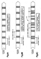
- Audio data is sent in packets holding a constant, chosen number of samples (chosen above to be 12), called the audio frame time 100 on the horizontal axis of Figure 3 .
- the time left over is called the unused network bandwidth time 110.
- the node 20 receives as input an analog audio input 140 (See Figure 9 ).
- Digital audio is sampled from the original analog with a converter 142 that measures the amplitude at regular intervals and passes this value (as a digital signal) on to the subsequent network node such as a node with a speaker as an output device coupled to an audio output 144.
- the digital signal needs to be turned back into analog, there is a reverse process performed by a converter that makes analog signals from the input numerical values.
- a common sampling clock must be used system-wide by nodes 20 on the network shown in Figure 1 . If each converter had an independent clock, the slight differences in the rate would mean that a buffer would be needed at the receiver, and even so, after some time the buffer would eventually over or under-flow and the audio would be interrupted.
- one terminal or node is designated to be the master clock source and implements a master clock 150 to which all the other nodes 20 are locked. (If the master clock is unplugged or fails, another node automatically takes its place in a seamless fashion.)
- a clock packet that contains a time value 152 is periodically sent by the source node but unlike the prior art patents referenced above this packet is not used to create time slots or to order the outputs of the transmitting terminals. Such control is not needed , because the invention uses switched Ethernet rather than a shared medium and has no need for timed access.
- the clock packet is not transmitted at the beginning of a sequence of audio packets. Rather, it is transmitted at a much lower rate and a PLL (Phase Locked Loop) circuit at each of the nodes increases the rate to provide a synchronized audio sample clock in receiving terminals or nodes.
- PLL Phase Locked Loop
- the ability to recover digital audio synchronization at multiple stations or nodes on the network relies on specialized statistical filtering of received timestamped clock information packets. Because packet switched networks can introduce a variable routing delay, a variable time delay is introduced into the communication of timing information, which would cause a variable timing synchronization error in all receivers. However, because the packet switched network can only add delay, it can never deliver a packet 'early'. This error is biased, and therefore can be mathematically filtered out.
- any devices communicating digitized audio information must operate off of an identical time base, or the digital audio information exchanged will not be able to be output, mixed, or otherwise combined with other audio channels.
- a straightforward solution of using sample rate conversion for each audio data stream has the undesirable penalty of creating audio delay due to the buffering required by the mathematical conversion filtering process.
- a desirable solution is to have a clock circuit in each device or receiver station which are all synchronized together to a common time reference.
- information must be communicated between them, allowing them to be adjusted to be synchronized. This synchronization information is itself sensitive to timing errors, that is to say time delays in the communication of synchronization information will prevent proper time synchronization.
- Packet switched networks have the property of delivery of packets of data with a variable time delay, dependent on the amount of network traffic. Since the network 10 transmits a mix of many types of packets from many senders to receivers at many different times, the switching delays experienced by clock packets are generally not precisely predictable, and have a variable, chaotic, and even a certain amount of random behavior.
- This switching delay normally prevents effective communication for use in synchronization of clocks , and is the fundamental problem to be solved in order to achieve node synchronization.
- one device in order to synchronize multiple clock devices, one device is chosen to be the master and implements a master clock 150, while all other devices become slaves which must follow and synchronize to the one master by implementing a slave clock 154.
- Choosing which device will be the master may be a manual operation, or an automatic one determined by a predetemined protocol exchanged via the communication network 10 in the event of a failure of the master.
- the master clock 150 is assumed not functioning any longer, and every possible new master transmits a preliminary clock message. If there are more than one new clock master candidate, the candidates vote themselves off in favor of the master detected with highest merit.
- the master with highest merit is determined from an assignment of unique values to each device, for example, such a the lowest ethernet network address value.
- the master marks and communicates time reference moments to all slaves, by a broadcast or multicast method of addressing all slaves with one packet.
- This packet contains a time reference count, called a timestamp value 152.
- This timestamp value 152 is a measure of time made by the master clock device in arbitrary time units. It is important that the value 152 is to be of high enough resolution to allow very small time differences or errors to be calculated by the slaves. In the exemplary implementation, the timestamp is in units of 1/12,288,000 Hz (approximately 80ns).
- the resulting data packet (called a clock packet ) is sent to the packet network 10 for communication to all the slaves.
- Each slave when it receives a clock packet, measures it own local clock device 154, for comparison to the master clock reference value 152 communicated inside the packet.
- the master clock reference value 152 communicated inside the packet.
- successive comparisons between the master and slave clock values are made at the slave node. If the comparison value is getting larger over time, then the slave clock 154 is running too fast, and a rate control adjustment is made to slow the slave clock down, and vice versa if the slave clock is found to be running too slow, a rate adjustment is made to speed it up.
- the specific formulas used to calculate the amount of rate adjustment given the amount of observed comparison differences over time may be many different standard control algorithms, including standard second order PLL (Phase Lock Loop), or PID (Proportional Integral Differential) control algorithms that are implemented in software.
- standard second order PLL Phase Lock Loop
- PID Proportional Integral Differential
- X is always greater than or equal to 0.
- X can never be negative. This means that X represents biased error in the time communication, and therefore this bias may be filtered out using a mathematical filter to eliminate it.
- the time variation for the clock packets is the sum of the queuing delays in the switches 22 resulting from all other packet traffic.
- a key observation is that if at the moment the clock packet arrives in the switch there are no other packets in progress of being sent, then the clock packet will be sent out immediately with minimum delay.
- the invention collects a set, or ensemble of clock packets in each receiver C.
- the size of this set that must be collected is determined by the statistics of the traffic on the packet network in use.
- the size of the set must be large enough so that given the variations of delivery time; the probability of at least some of the clock packets having been received without extra delay is significantly close to 1. There at least two methods for calculating an estimate of this probability.
- a first method estimates the probability is based on a determination of the ratio of network free time B as a percentage of all time B+A. Given the expected network traffic density, this method chooses the time interval of collecting the clock packets such that the probability of having network free time is greater than zero.
- a second probability estimate illustrated in Figure 5B is derived from a property of the behavior of the packet Ethernet switch that determines the probability of high priority clock packets propagating through the links of the network with minimum delay: The ratio of the desired definition of 'minimum' delay to the transmission time of a maximum size packet. From the moment a high priority clock packet arrives in the switch, it will be next to be sent out by virtue of its high priority, but must wait for any current packet then being transmitted to complete. If we define a 'minimum' delay to be say 1 usec, and the maximum packet is 120 usec long (for 100bt Ethernet), then the probability over time that a clock packet will arrive less than 1 usec before the end of the previous packet transmission is complete is 1/120. Therefore even with network capacity at 100%, if we collect 120 clock packets, the odds will be close to certainty that at least one of the clock packets has experienced a delay less than 1 usec in the switch.
- an exemplary system For a packet switched network carrying digital audio traffic streams of some amount, say 80% capacity, plus command and control information for those digital audio devices, an exemplary system has a very high probability of some clock packets arriving with minimum variable delay by collecting between 50 and 250 clock packets over an interval of 200milliseconds to 1 second.
- the set of clock packets is collected, observe a histogram 156 of the comparisons made between the master clock and the local slave clock. It is observed that the set of time comparisons will be spread from a minimum to a maximum value. Since both the master 150 and slave clocks 154 are stable relative to real time (they only differ in rate), the variation may be attributed solely to the variable network delay. Therefore, the time measurement values at the minimum range of the histogram are the clock packets that experienced the minimum extra network delay. All other packets may be ignored, and the values from minimum end of the histogram are used to perform the slave clock rate adjustment calculation discussed previously.
- the process since it is known ahead of time that at the end of the histogram process, the process only uses the minimum range value, it does not need to store the data for the entire histogram. Rather, it simply finds the minimum time difference value of the set of clock packets as they arrive.
- the exemplary embodiment of the invention uses a novel design for transmitting timestamped clock references on packet switched networks allowing optimal clock synchronization recovery that is particularly advantageous for use with audio data transmission.
- the disclosed exemplary embodiment of the invention uses a process for sending timestamped clock references, which optimizes clock recovery when using a statistical filtering synchronization scheme in each receiver.
- the probability of at least some clock packets arriving with minimum delay must be close to 1. This probability is an interaction of the characteristics of the network traffic, and the characteristics of when and how the clock packets are sent.
- the characteristics of the network traffic is regarded as outside the control of the system (in order to not place constraints on the system).
- the design of the transmission of clock packets is made to optimize the required high probability.
- the delay statistics of the network are really the statistics of all the other traffic on the network.
- the overall traffic pattern is arbitrary and random. Because the overall traffic patterns are arbitrary, there may indeed be traffic patterns that have pronounced repetitive periodic pattern, bursts, or long streams of bursts. It cannot be assumed that overall traffic is statistically 'random' in the sense of lacking structure, it may have pronounced, (but arbitrary) structure.
- the pattern of transmission of timestamped clock reference packets is chosen so that at least some of the time the clock reference packets traverse the entire network to the intended receivers with minimum delay. Note any given clock packet broadcast onto the network by the master does not have to reach all receivers with minimum delay, it is sufficient that at least some of the time some clock packets reach each receiver with minimum delay.
- the network traffic is undefined, but is not completely random. Two dominant traffic commonly appear that are characteristic of a wide class of data flows:
- Bursty traffic is when a relatively large amount of data needs to be transferred, but only once. When the data transfer is demanded, it may take many packets of network transfer to complete the required data transfer, and these all complete with as minimum delay as possible. Therefore, a group of transfers happens together (a burst), until the overall data request is complete, and then the network transfers stop. Network protocols like TCP/IP have mechanisms to spread out these bursts somewhat, to promote sharing of the network even during large bursts.
- the characteristics of bursty network traffic are the statistics of the burst length (Bt), and the time gaps between the bursts, called the burst gap (Gt) .
- the length of time covered by the set of clock packets C(set)t should be greater than the maximum expected burst length time Bt . Otherwise, all the clock packets of a set may be delayed by the existing network burst. In practice, if the priority of the clock packets is set higher than the bursty network traffic, than this constraint on the design of the clock packets set size may be relaxed.
- Isochronous network traffic is when a certain amount of data is transferred periodically by the network.
- the 'iso-' name comes from the fact that these data transfers are not in exact synchronization with time, since the variable delay of packet network delivery prevents this. They are approximately periodic in time, having a period P and may continue to exist for extended or indefinite periods of time (that is, they may never stop).
- Many multimedia streams carried on networks form isochronous traffic patterns.
- a bandwidth sharing algorithm such as TCP/IP controls a large burst transfer in order to throttle back and use less network bandwidth, it may for a certain duration, create a stream of packets, spaced out at some pseudo-interval. This is not true isochronous traffic, but it has the same potential for colliding with and disrupting clock packets.
- the isochronous traffic pattern has the greatest potential to disrupt the communication of synchronization information over the packet network. This is because the potential exists that any isochronous stream may happen to have the same or similar interval as chosen for a given set of clock packets communicated for the purpose of clock synchronization. In this case, even if the clock packets are set to a higher priority than the isochronous stream, each and every clock packet may still experience queuing delay in a switch 22, since at each and every moment a clock packet arrives at the switch, a packet from some isochronous stream may have just started transmission. This 'accidental correlation' between the isochronous streams and the clock packet sequence period Cp is avoided by practice of the present invention.
- a pattern of random intervals 170, or sufficiently pseudo-random interval pattern is chosen for the transmission of the timestamped clock reference packets. Statistically, this ensures on the whole, that at least some of the clock reference packets will reach each receiver free of conflict from overall other traffic, and fulfill the requirements for allowing clock synchronization recovery.
- These random intervals are determined in software or hardware by the node designated as the master and at the beginning of each such interval, the node broadcasts a timestamped clock packet onto the network 10.
- a node 20 depicted in Fig 9 There are two signal flow paths represented in a node 20 depicted in Fig 9 , receive and transmit.
- the receive path flows from top to bottom, and the transmit is bottom to top.
- the receive path begins with packets coming in from the ethernet network via the Ethernet Physical Interface 210.
- This devise transcodes the particular electrical, wireless, or optical signal format used for transmission between nodes, into standard digital logic signals.
- the Ethernet physical interface 210 presents the data of the incoming packets to a packet receiving circuit.
- a packet filter 212 tests the data in each received packet of data to see if it belongs to one of the audio streams, or contains clock sync information; or not. If neither audio nor a clock packet, the packet either represents non-audio data for that node or is addressed to another node. If the packet contains non-audio data a node processor interprets that data in a conventional manner. The packet filter does this by comparing the destination address contained inside the data packet, with a list of destination addresses that the receiving terminal is programmed to accept. The list of accepted destination address numbers is programmed by a node processor 213 into the packet filter ahead of time depending on which audio channels from the network the user desires to come out of the outputs of this audio receive terminal. If the packet address does not match any of the accepted destination addresses on the list, no further action is taken on that packet and it is simply ignored. If the packet address does match an accepted address on the list, which address it matches determines the next step of processing the incoming packet.
- a time measurement of the local clock 214 is triggered, and the local time clock value along with the received clock packet contents is stored. This storage event notifies the software running on the node processor that a new clock packet has arrived.
- Software on the node processor reads the clock packet information and compares the local clock to the remote master clock by performing a histogram statistical clock filtering algorithm. The clock filtering algorithm may result in a decision to adjust the local clock to make this local clock 214 either faster or slower using a software implemented phase lock loop 216.
- the packet destination address matches one of the audio channel addresses on the list, then that packet is routed and stored into a corresponding audio channel buffer 220. That is, if the audio packet address matches the first audio channel address on the list, then the audio data is put into the first audio channel buffer, matching the second address on the list goes into the second audio channel buffer, and so forth
- the audio channel buffers 220 are maintained in FIFO order, and read out at a periodic rate determined by the local sample clock, serialized, and sent to the Digital to Analog (D/A) converter 222 to be converted into an analog audio signal output 144 (or sent to an AES/EBU transmitter to become a standard digital audio signal).
- D/A Digital to Analog
- the audio channel buffer will be emptied by the D/A converter 222 faster than it is filled from network audio packets, which results in underflow and an interruption of the audio.
- the audio channel buffer will become full, resulting in overflow and likewise a loss of audio data. Both of these conditions are avoided by the proper synchronization of the local clock 214 to the remote master clock 150 so that the net empty and fill rates of the buffers is the same.
- the receive audio channel buffers 220 must be properly initialized so that they contain the chosen average amount of audio data corresponding to the buffer size outlined previously.
- the maximum capacity of the FIFO is not the buffer size we desire (for the example of 24 audio samples outlined).
- the 'N input channel buffers' should show nominally 24 samples each.
- the 'N output channel buffers' should remain nominally 12 samples each)) audio samples contained in the FIFO at the moment of the beginning of an audio frame period.
- the maximum capacity of the FIFO memory may be any number larger than the required buffer size, and is not an important parameter of this design.
- One of at least two methods may be used to initialize the receive FIFO audio buffers 220.
- the first method is to empty the buffer, while disabling the output. Then, after 24 samples (2 nominal audio frames) have come in from the network, enable the output.
- the second method is to directly manipulate the internal FIFO memory storage pointers. At the moment the FIFO begins to be filled, set the output pointer equal to the input pointer minus 24 audio samples (or alternatively at this moment set the input pointer to the output pointer plus 24 audio samples). Both of these methods will initialize the received audio channel buffer FIFO to have nominally the chosen buffer occupancy size.
- the receive channel buffer is implemented in certain nodes using a field programmable gate array (FPGA) commercially available from Xilinx. It includes memory for the buffers and programmable logic for maintaining those buffers. Other nodes, such as PC based nodes implement these buffers completely in software that interaces with a standard network interface card.
- FPGA field programmable gate array
- Transmit data originates from the Analog to Digital converters 142 (A/D) transcoding analog audio into digital numerical values (or digital numerical values may be received directly from AES/EBU digital audio receivers.
- A/D Analog to Digital converters 142
- This data is received serially, converted to parallel by a converter 224 and stored into an appropriate transmit audio channel buffer 230.
- the transmit audio channel buffers collect enough audio samples to form a complete audio packet. (In the exemplary embodiment this is the data for 12 audio samples).
- the packet transmit is triggered.
- the packet generator takes the audio data out of the channel buffer and builds an audio packet, adds the packet header information, computes and adds a CRC check value to the end, and sends the packet to the Ethernet physical interface 210.
- the audio data from channel buffer 1 is given the packet destination address for the first output audio channel
- buffer 2 is given the address for channel 2, and so forth.
- the destination addresses are determined by the node processor software ahead of time and programmed into the packet generator, as the user configures how the audio channels are to be configured for routing.
- the Ethernet physical interface 210 transcodes the packet data into signaling to the network connection (wires, wireless, or fiber optic).
- the buffer synchronization of the transmit mechanism is much simpler than the mechanism for initializing the buffers for receive. It is sufficient to simply wait for the transmit buffers to be full enough, and then transmit audio packets.
Landscapes
- Engineering & Computer Science (AREA)
- Computer Networks & Wireless Communication (AREA)
- Signal Processing (AREA)
- Multimedia (AREA)
- Data Exchanges In Wide-Area Networks (AREA)
- Small-Scale Networks (AREA)
Claims (10)
- Verfahren zum Liefern von Audisignalen von einem Sourceknoten (B) zu einem Bestimmungsknoten (C) auf einem paketgeschalteten Netzwerk mit den Schritten:Bereitstellen einer Anzahl von Netzwerkschaltern (22), die priorisierte Daten auf einem paketgeschalteten Netzwerk übertragen; undVerbinden eines Schalters (22) mit einer Anzahl von Knoten (B, C) zum Senden und Empfangen von digitalen Audiosignalen auf dem paketgeschalteten Netzwerk; undBeschränken einer Empfangspuffergröße von zumindest einigen der Bestimmungsknoten, so dass die Beziehung erfüllt ist:

wobeiTAF = Audioframezeit,TTMAX = Übertragungszeit des Pakets der maximalen Größe auf dem paketgeschalteten Netzwerk undNSW = Anzahl der zwischenliegenden Netzwerkknoten (22), die die Pakete zwischen dem Sourceknoten (B) und dem Bestimmungsknoten (C) durchlaufen, um die Verzögerung bei der Verarbeitung von Audiosignalen, die an dem Bestimmungsknoten (C) ankommen, zu minimieren. - Verfahren nach Anspruch 1, zusätzlich mit dem Schritt des Zuordnens von einer Priorität zu Datenpaketen an dem Sourceknoten beruhend darauf, ob es ein Audio- oder Nichtaudiopaket ist, wobei Audiopakete eine höhere Priorität erhalten, um die Schalter, die zwischen den Knoten angeordnet sind, zu veranlassen, die Pakete durch den Schalter, die von einem Sourceknoten erhalten werden, beruhend auf der Priorität der Datenpakete durchzulassen.
- Verfahren nach Anspruch 1, zusätzlich mit:Beibehalten eines Mastertakts an einem bestimmten Knoten des Netzwerks;in Intervallen Kodieren eines Zeitsteuerungspaketes zur Übertragung von einem oder mehreren anderen Knoten an dem Netzwerk; undBestimmen der Zeitsteuerungspakete, die mit dem kleinsten Zeitfehler empfangen wurden, beim Herausfinden der minimalen Netzwerkübertragungszeit zwischen dem bestimmten Knoten und dem einen oder mehreren anderen Knoten, indem der minimale Zeitoffset von einem Satz oder einer Gruppe von mehreren Zeitsteuerungspaketen gefunden wird; unddann Verwenden nur der Zeitsteuerungspakete, die mit dem kleinsten Zeitfehler empfangen wurden zum Synchronisieren eines lokalen Takts, der an dem einen oder mehreren Knoten beibehalten wird, mit dem Takt des vorgegebenen Knotens.
- Verfahren nach Anspruch 3, bei dem der Schritt des Synchronisierens an jedem Knoten durch eine digitale Phasenregelschleife durchgeführt wird, die die Vergleichsinformation von den Zeitsteuerungspaketen nimmt, die mit dem kleinsten Zeitsteuerungsfehler empfangen wurden, der durch Paketnetzwerksverzögerungszeit eingeführt wird, und die die Ratensteuerungseinstellung berechnet, um den lokalen Takt an dem Knoten in Synchronisation mit dem Mastertakt zu bringen.
- Verfahren nach Anspruch 3, bei dem der Masterknoten eine Mehrzahl von Zeitsteuerungspaketen an das Netzwerk mit unregelmäßigen oder Pseudozufallsintervallen sendet, um die Wahrscheinlichkeit zu erhöhen, dass zumindest einige der Zeitsteuerungspakete an dem einen oder mehreren anderen Knoten mit minimaler Netzwerkdurchgangsverzögerungszeit ankommen.
- Vorrichtung (10) zur Lieferung von Audiosignalen von einem Sourceknoten (B) an einen Bestimmungsknoten (C) auf einem paketgeschalteten Netzwerk mit:einer Anzahl von Netzwerkschaltern (22), die priorisierte Daten auf dem paketgeschalteten Netzwerk übertragen; undeiner Anzahl von Sender/Empfängerknoten (B, C) zum Senden und Empfangen von digitalen Audiosignalen auf dem paketgeschalteten Netzwerk; undwobei einer oder mehrere der Bestimmungsknoten (C) einen Empfangspuffer mit einer Größe haben, um eine Menge von Audiodaten zu erhalten, so dass die Menge der Zeit, die durch die Audioabtastdaten repräsentiert wird, die in dem Empfangspuffer gespeichert sind, beschränkt ist, um die folgende Beziehung zu erfüllen:um die Verzögerung bei der Verarbeitung von Audiosignalen, die an dem Bestimmungsknoten (C) ankommen, zu minimieren.

wobeiTAF = Audioframezeit,TTMAX = Übertragungszeit des Paketes der maximalen Größe auf dem paketgeschalteten Netzwerk undNSW = Anzahl der zwischenliegenden Netzwerkknoten (22), durch die die Pakete zwischen dem Sourceknoten (B) und dem Bestimmungsknoten (C) durchlaufen; - Vorrichtung nach Anspruch 6, zusätzlich mit einem Paketgenerator in einem Sourceknoten zum Zuordnen einer Priorität zu Datenpaketen an dem Sourceknoten beruhend darauf, ob das Paket ein Audio- oder ein Nichtaudiopaket ist, wobei Audiopakete höhere Priorität erhalten, um die Schalter zum Übertragen von Paketen durch den Schalter, die von dem Sourceknoten empfangen werden, basierend auf der Priorität des Datenpakets zu dirigieren.
- Vorrichtung nach Anspruch 6, des Weiteren mit:einem bestimmten Knoten (A) des Netzwerks mit einer Digitalschaltung zum Implementieren eines Mastertakts, der mit Intervallen ein Zeitsteuerungspakete zur Übertragung auf dem Netzwerk kodiert; undein oder mehrere andere Knoten auf dem Netzwerk mit einem Prozessor zum Bestimmen der Zeitsteuerungspakete, die mit dem kleinsten Zeitsteuerungsfehler erhalten werden, um die minimale Netzwerkdurchgangszeit zwischen dem Masterknoten und einem oder mehreren anderen Knoten zu finden, um einen minimalen Zeitoffset aus einem Satz oder einer Gruppe von mehreren Zeitsteuerungspaketen zu finden, um unter Verwendung nur der Zeitsteuerungspakete, die mit dem kleinsten Zeitsteuerungsfehler empfangen wurden, einen lokalen Takt mit dem Mastertakt zu synchronisieren.
- Vorrichtung nach Anspruch 8, bei der ein oder mehrere Knoten eine digitale Phasenregelschleife enthalten, die die Zeitvergleichsinformation aus den Zeitsteuerungspaketen, die mit dem kleinsten Zeitsteuerungsfehler erhalten werden, der durch das Paketnetzwerk eingefügt wurde, und die die Ratensteuerungseinstellung berechnet, um den lokalen Takt an dem Knoten in Synchronisation mit dem Mastertakt zu bringen.
- Vorrichtung nach Anspruch 8, bei der der Masterknoten eine Mehrzahl von Zeitsteuerungspaketen auf das Netzwerk mit unregelmäßigen oder Pseudozufallintervallen sendet, um die Wahrscheinlichkeit zu erhöhen, dass zumindest einige der Zeitsteuerungspakete an dem einen oder mehreren anderen Knoten mit einer minimalen Netzwerkdurchgangsverzögerungszeit ankommen.
Applications Claiming Priority (4)
| Application Number | Priority Date | Filing Date | Title |
|---|---|---|---|
| US43392202P | 2002-12-17 | 2002-12-17 | |
| US433922P | 2002-12-17 | ||
| US10/406,396 US7555017B2 (en) | 2002-12-17 | 2003-04-03 | Low latency digital audio over packet switched networks |
| US406396 | 2003-04-03 |
Publications (3)
| Publication Number | Publication Date |
|---|---|
| EP1432203A2 EP1432203A2 (de) | 2004-06-23 |
| EP1432203A3 EP1432203A3 (de) | 2007-12-05 |
| EP1432203B1 true EP1432203B1 (de) | 2013-01-09 |
Family
ID=32396941
Family Applications (1)
| Application Number | Title | Priority Date | Filing Date |
|---|---|---|---|
| EP03025357A Expired - Lifetime EP1432203B1 (de) | 2002-12-17 | 2003-11-04 | Niedrige Latenzzeit für digitale Audiopakete über ein paketvermittelndes Netz |
Country Status (2)
| Country | Link |
|---|---|
| US (3) | US7555017B2 (de) |
| EP (1) | EP1432203B1 (de) |
Cited By (9)
| Publication number | Priority date | Publication date | Assignee | Title |
|---|---|---|---|---|
| US8370554B2 (en) | 2009-05-18 | 2013-02-05 | Stmicroelectronics, Inc. | Operation of video source and sink with hot plug detection not asserted |
| US8385544B2 (en) | 2003-09-26 | 2013-02-26 | Genesis Microchip, Inc. | Packet based high definition high-bandwidth digital content protection |
| US8429440B2 (en) | 2009-05-13 | 2013-04-23 | Stmicroelectronics, Inc. | Flat panel display driver method and system |
| US8468285B2 (en) | 2009-05-18 | 2013-06-18 | Stmicroelectronics, Inc. | Operation of video source and sink with toggled hot plug detection |
| US8582452B2 (en) | 2009-05-18 | 2013-11-12 | Stmicroelectronics, Inc. | Data link configuration by a receiver in the absence of link training data |
| US8671234B2 (en) | 2010-05-27 | 2014-03-11 | Stmicroelectronics, Inc. | Level shifting cable adaptor and chip system for use with dual-mode multi-media device |
| US8760461B2 (en) | 2009-05-13 | 2014-06-24 | Stmicroelectronics, Inc. | Device, system, and method for wide gamut color space support |
| US8788716B2 (en) | 2009-05-13 | 2014-07-22 | Stmicroelectronics, Inc. | Wireless multimedia transport method and apparatus |
| US8860888B2 (en) | 2009-05-13 | 2014-10-14 | Stmicroelectronics, Inc. | Method and apparatus for power saving during video blanking periods |
Families Citing this family (106)
| Publication number | Priority date | Publication date | Assignee | Title |
|---|---|---|---|---|
| US7065586B2 (en) * | 2000-12-22 | 2006-06-20 | Radiance Technologies, Inc. | System and method for scheduling and executing data transfers over a network |
| US7142508B2 (en) * | 2000-12-22 | 2006-11-28 | Radiance Technologies, Inc. | System and method for controlling data transfer rates on a network |
| CH704101B1 (de) * | 2002-11-06 | 2012-05-31 | Barix Ag | Verfahren und Vorrichtung zur synchronisierten Wiedergabe von Datenströmen. |
| US7555017B2 (en) * | 2002-12-17 | 2009-06-30 | Tls Corporation | Low latency digital audio over packet switched networks |
| US7379480B2 (en) * | 2003-01-16 | 2008-05-27 | Rockwell Automation Technologies, Inc. | Fast frequency adjustment method for synchronizing network clocks |
| US20040218624A1 (en) * | 2003-05-01 | 2004-11-04 | Genesis Microchip Inc. | Packet based closed loop video display interface with periodic status checks |
| US20040218599A1 (en) * | 2003-05-01 | 2004-11-04 | Genesis Microchip Inc. | Packet based video display interface and methods of use thereof |
| US20040221315A1 (en) * | 2003-05-01 | 2004-11-04 | Genesis Microchip Inc. | Video interface arranged to provide pixel data independent of a link character clock |
| US7424558B2 (en) * | 2003-05-01 | 2008-09-09 | Genesis Microchip Inc. | Method of adaptively connecting a video source and a video display |
| US7567592B2 (en) | 2003-05-01 | 2009-07-28 | Genesis Microchip Inc. | Packet based video display interface enumeration method |
| US8059673B2 (en) * | 2003-05-01 | 2011-11-15 | Genesis Microchip Inc. | Dynamic resource re-allocation in a packet based video display interface |
| US7839860B2 (en) * | 2003-05-01 | 2010-11-23 | Genesis Microchip Inc. | Packet based video display interface |
| US8068485B2 (en) | 2003-05-01 | 2011-11-29 | Genesis Microchip Inc. | Multimedia interface |
| US7733915B2 (en) * | 2003-05-01 | 2010-06-08 | Genesis Microchip Inc. | Minimizing buffer requirements in a digital video system |
| US7405719B2 (en) | 2003-05-01 | 2008-07-29 | Genesis Microchip Inc. | Using packet transfer for driving LCD panel driver electronics |
| US8204076B2 (en) * | 2003-05-01 | 2012-06-19 | Genesis Microchip Inc. | Compact packet based multimedia interface |
| US7620062B2 (en) * | 2003-05-01 | 2009-11-17 | Genesis Microchips Inc. | Method of real time optimizing multimedia packet transmission rate |
| FR2858895B1 (fr) * | 2003-08-13 | 2006-05-05 | Arteris | Procede et dispositif de gestion de priorite lors de la transmission d'un message |
| US7487273B2 (en) * | 2003-09-18 | 2009-02-03 | Genesis Microchip Inc. | Data packet based stream transport scheduler wherein transport data link does not include a clock line |
| US7800623B2 (en) * | 2003-09-18 | 2010-09-21 | Genesis Microchip Inc. | Bypassing pixel clock generation and CRTC circuits in a graphics controller chip |
| US20050068987A1 (en) * | 2003-09-24 | 2005-03-31 | Schaik Carl Van | Highly configurable radar module link |
| US7613300B2 (en) * | 2003-09-26 | 2009-11-03 | Genesis Microchip Inc. | Content-protected digital link over a single signal line |
| US20050100023A1 (en) * | 2003-11-07 | 2005-05-12 | Buckwalter Paul B. | Isochronous audio network software interface |
| US7729267B2 (en) | 2003-11-26 | 2010-06-01 | Cisco Technology, Inc. | Method and apparatus for analyzing a media path in a packet switched network |
| US7519006B1 (en) * | 2003-11-26 | 2009-04-14 | Cisco Technology, Inc. | Method and apparatus for measuring one-way delay at arbitrary points in network |
| US7539142B1 (en) * | 2004-07-21 | 2009-05-26 | Adtran, Inc. | Ethernet LAN interface for T3 network |
| US7792158B1 (en) | 2004-08-18 | 2010-09-07 | Atheros Communications, Inc. | Media streaming synchronization |
| US8149880B1 (en) * | 2004-08-18 | 2012-04-03 | Qualcomm Atheros, Inc. | Media streaming synchronization |
| US7440474B1 (en) * | 2004-09-15 | 2008-10-21 | Avaya Inc. | Method and apparatus for synchronizing clocks on packet-switched networks |
| US20060083259A1 (en) * | 2004-10-18 | 2006-04-20 | Metcalf Thomas D | Packet-based systems and methods for distributing data |
| TWI364191B (en) * | 2004-11-19 | 2012-05-11 | Northrop Grumman Corp | Real-time packet processing system and method |
| JP4900891B2 (ja) | 2005-04-27 | 2012-03-21 | キヤノン株式会社 | 通信装置及び通信方法 |
| US8074248B2 (en) | 2005-07-26 | 2011-12-06 | Activevideo Networks, Inc. | System and method for providing video content associated with a source image to a television in a communication network |
| US7526526B2 (en) * | 2005-10-06 | 2009-04-28 | Aviom, Inc. | System and method for transferring data |
| US20070104332A1 (en) * | 2005-10-18 | 2007-05-10 | Clemens Robert P | System and method for automatic plug detection |
| US8724615B1 (en) | 2005-10-11 | 2014-05-13 | Atmel Corporation | Method and apparatus for generation of a system master timebase of a computing device using indirect signalling of timing information |
| US20070201491A1 (en) * | 2006-02-28 | 2007-08-30 | Ron Kapon | System and method for synchronizing serial digital interfaces over packet data networks |
| US7796650B2 (en) * | 2006-03-10 | 2010-09-14 | Acterna Llc | Device and method for determining a voice transmission delay over a packet switched network |
| US8032672B2 (en) | 2006-04-14 | 2011-10-04 | Apple Inc. | Increased speed of processing of audio samples received over a serial communications link by use of channel map and steering table |
| US20080065925A1 (en) * | 2006-09-08 | 2008-03-13 | Oliverio James C | System and methods for synchronizing performances of geographically-disparate performers |
| US7738383B2 (en) | 2006-12-21 | 2010-06-15 | Cisco Technology, Inc. | Traceroute using address request messages |
| US8660039B2 (en) * | 2007-01-08 | 2014-02-25 | Intracom Systems, Llc | Multi-channel multi-access voice over IP intercommunication systems and methods |
| EP2106665B1 (de) | 2007-01-12 | 2015-08-05 | ActiveVideo Networks, Inc. | Interaktives verschlüsseltes inhaltssystem mit objektmodellen zur ansicht auf einem ferngerät |
| US9826197B2 (en) | 2007-01-12 | 2017-11-21 | Activevideo Networks, Inc. | Providing television broadcasts over a managed network and interactive content over an unmanaged network to a client device |
| US7706278B2 (en) | 2007-01-24 | 2010-04-27 | Cisco Technology, Inc. | Triggering flow analysis at intermediary devices |
| US20080281455A1 (en) * | 2007-05-11 | 2008-11-13 | Kenneth Swegman | Materials, Operations and Tooling Interface and Methods for Managing a Remote Production Facility |
| US20080285551A1 (en) * | 2007-05-18 | 2008-11-20 | Shamsundar Ashok | Method, Apparatus, and Computer Program Product for Implementing Bandwidth Capping at Logical Port Level for Shared Ethernet Port |
| US20090094658A1 (en) * | 2007-10-09 | 2009-04-09 | Genesis Microchip Inc. | Methods and systems for driving multiple displays |
| US7729075B2 (en) * | 2007-10-31 | 2010-06-01 | Agere Systems Inc. | Low-power read channel for magnetic mass storage systems |
| US8804627B2 (en) * | 2007-12-19 | 2014-08-12 | Qualcomm Incorporated | Method and apparatus for improving performance of erasure sequence detection |
| FR2925804B1 (fr) * | 2007-12-20 | 2010-01-01 | Canon Kk | Procede de gestion de delais dans un commutateur, commutateur, produit programme d'ordinateur et moyen de stockage correspondants |
| US7774521B2 (en) * | 2007-12-28 | 2010-08-10 | Intel Corporation | Method and apparatus for reducing power consumption for isochronous data transfers |
| US7680154B2 (en) * | 2007-12-31 | 2010-03-16 | Intel Corporation | Methods and apparatus for synchronizing networked audio devices |
| US20090219932A1 (en) * | 2008-02-04 | 2009-09-03 | Stmicroelectronics, Inc. | Multi-stream data transport and methods of use |
| JPWO2009119633A1 (ja) * | 2008-03-26 | 2011-07-28 | 日本電気株式会社 | データ通信処理装置及び方法 |
| US20090262667A1 (en) * | 2008-04-21 | 2009-10-22 | Stmicroelectronics, Inc. | System and method for enabling topology mapping and communication between devices in a network |
| US7839789B2 (en) * | 2008-12-15 | 2010-11-23 | Verizon Patent And Licensing Inc. | System and method for multi-layer network analysis and design |
| US20100183004A1 (en) * | 2009-01-16 | 2010-07-22 | Stmicroelectronics, Inc. | System and method for dual mode communication between devices in a network |
| US8291207B2 (en) * | 2009-05-18 | 2012-10-16 | Stmicroelectronics, Inc. | Frequency and symbol locking using signal generated clock frequency and symbol identification |
| GB0908884D0 (en) | 2009-05-22 | 2009-07-01 | Zarlink Semiconductor Inc | Time recovery over packet networks |
| US9191721B2 (en) * | 2009-06-16 | 2015-11-17 | Harman International Industries, Incorporated | Networked audio/video system |
| US8385212B2 (en) * | 2009-12-07 | 2013-02-26 | Symmetricom, Inc. | Method and apparatus for finding latency floor in packet networks |
| TWI419519B (zh) * | 2009-12-22 | 2013-12-11 | Ind Tech Res Inst | 適用於多媒體串流的網路封包傳送系統與方法 |
| GB201002217D0 (en) * | 2010-02-10 | 2010-03-31 | Zarlink Semiconductor Inc | Clock recovery method over packet switched networks based on network quiet period detection |
| US20110205894A1 (en) * | 2010-02-24 | 2011-08-25 | Microsoft Corporation | Traffic shaping for real time media streams |
| AU2010350058A1 (en) * | 2010-03-31 | 2012-10-18 | Robert Bosch Gmbh | Method and apparatus for authenticated encryption of audio |
| US8432931B2 (en) * | 2010-06-15 | 2013-04-30 | Dell Products L.P. | System and method for information handling system wireless audio driven antenna |
| US8837529B2 (en) | 2010-09-22 | 2014-09-16 | Crestron Electronics Inc. | Digital audio distribution |
| JP5866125B2 (ja) | 2010-10-14 | 2016-02-17 | アクティブビデオ ネットワークス, インコーポレイテッド | ケーブルテレビシステムを使用したビデオ装置間のデジタルビデオストリーミング |
| US8774010B2 (en) | 2010-11-02 | 2014-07-08 | Cisco Technology, Inc. | System and method for providing proactive fault monitoring in a network environment |
| US8559341B2 (en) | 2010-11-08 | 2013-10-15 | Cisco Technology, Inc. | System and method for providing a loop free topology in a network environment |
| WO2012095120A1 (de) * | 2011-01-11 | 2012-07-19 | Siemens Enterprise Communications Gmbh & Co.Kg | Verfahren zur taktsynchronisation einer mehrzahl von baugruppen |
| US20120207178A1 (en) * | 2011-02-11 | 2012-08-16 | Webb Iii Charles A | Systems and methods utilizing large packet sizes to reduce unpredictable network delay variations for timing packets |
| US8982733B2 (en) | 2011-03-04 | 2015-03-17 | Cisco Technology, Inc. | System and method for managing topology changes in a network environment |
| US8670326B1 (en) | 2011-03-31 | 2014-03-11 | Cisco Technology, Inc. | System and method for probing multiple paths in a network environment |
| EP2695388B1 (de) * | 2011-04-07 | 2017-06-07 | ActiveVideo Networks, Inc. | Latenzreduktion in videoverteilungsnetzwerken mit adaptiver bitrate |
| US20120281704A1 (en) | 2011-05-02 | 2012-11-08 | Butterworth Ashley I | Methods and apparatus for isochronous data delivery within a network |
| US8724517B1 (en) | 2011-06-02 | 2014-05-13 | Cisco Technology, Inc. | System and method for managing network traffic disruption |
| US8830875B1 (en) | 2011-06-15 | 2014-09-09 | Cisco Technology, Inc. | System and method for providing a loop free topology in a network environment |
| US10107893B2 (en) * | 2011-08-05 | 2018-10-23 | TrackThings LLC | Apparatus and method to automatically set a master-slave monitoring system |
| US10409445B2 (en) | 2012-01-09 | 2019-09-10 | Activevideo Networks, Inc. | Rendering of an interactive lean-backward user interface on a television |
| US9014029B1 (en) * | 2012-03-26 | 2015-04-21 | Amazon Technologies, Inc. | Measuring network transit time |
| US9800945B2 (en) | 2012-04-03 | 2017-10-24 | Activevideo Networks, Inc. | Class-based intelligent multiplexing over unmanaged networks |
| US9123084B2 (en) | 2012-04-12 | 2015-09-01 | Activevideo Networks, Inc. | Graphical application integration with MPEG objects |
| US9088514B2 (en) * | 2012-07-23 | 2015-07-21 | Broadcom Corporation | Flexray communications using ethernet |
| JP5978861B2 (ja) * | 2012-08-31 | 2016-08-24 | 富士通株式会社 | 通信装置及び通信方法 |
| US9450846B1 (en) | 2012-10-17 | 2016-09-20 | Cisco Technology, Inc. | System and method for tracking packets in a network environment |
| US10275128B2 (en) | 2013-03-15 | 2019-04-30 | Activevideo Networks, Inc. | Multiple-mode system and method for providing user selectable video content |
| US9219922B2 (en) | 2013-06-06 | 2015-12-22 | Activevideo Networks, Inc. | System and method for exploiting scene graph information in construction of an encoded video sequence |
| US9294785B2 (en) | 2013-06-06 | 2016-03-22 | Activevideo Networks, Inc. | System and method for exploiting scene graph information in construction of an encoded video sequence |
| WO2014197879A1 (en) | 2013-06-06 | 2014-12-11 | Activevideo Networks, Inc. | Overlay rendering of user interface onto source video |
| JP6171595B2 (ja) * | 2013-06-07 | 2017-08-02 | 富士通株式会社 | パケット中継装置及びパケット送信装置 |
| JP5937045B2 (ja) * | 2013-08-28 | 2016-06-22 | 日本電信電話株式会社 | 遅延揺らぎ推定方法および遅延揺らぎ推定装置 |
| US9788029B2 (en) | 2014-04-25 | 2017-10-10 | Activevideo Networks, Inc. | Intelligent multiplexing using class-based, multi-dimensioned decision logic for managed networks |
| CN105281884B (zh) * | 2014-07-24 | 2019-02-22 | 北京信威通信技术股份有限公司 | 一种无中心网络中的节点时间同步方法 |
| US9521057B2 (en) | 2014-10-14 | 2016-12-13 | Amazon Technologies, Inc. | Adaptive audio stream with latency compensation |
| US10423468B2 (en) * | 2015-02-10 | 2019-09-24 | Red Hat, Inc. | Complex event processing using pseudo-clock |
| US9891966B2 (en) | 2015-02-10 | 2018-02-13 | Red Hat, Inc. | Idempotent mode of executing commands triggered by complex event processing |
| US10013229B2 (en) * | 2015-04-30 | 2018-07-03 | Intel Corporation | Signal synchronization and latency jitter compensation for audio transmission systems |
| CN105681974A (zh) * | 2016-04-01 | 2016-06-15 | 北京小鸟听听科技有限公司 | 多音源切换方法、装置及音频设备 |
| CN107171896A (zh) * | 2017-07-01 | 2017-09-15 | 安徽明阳信息技术有限公司 | 一种以太网时延计算方法及装置 |
| GB201720612D0 (en) * | 2017-12-11 | 2018-01-24 | Nordic Semiconductor Asa | Radio communications |
| US11062722B2 (en) * | 2018-01-05 | 2021-07-13 | Summit Wireless Technologies, Inc. | Stream adaptation for latency |
| JP7059959B2 (ja) * | 2019-02-12 | 2022-04-26 | トヨタ自動車株式会社 | 車載ネットワークシステム |
| CN109831268B (zh) * | 2019-03-15 | 2020-05-29 | 武汉电信器件有限公司 | 一种以太网电口时钟同步方法、系统和装置 |
| US11921927B1 (en) | 2021-10-14 | 2024-03-05 | Rockwell Collins, Inc. | Dynamic and context aware cabin touch-screen control module |
Family Cites Families (28)
| Publication number | Priority date | Publication date | Assignee | Title |
|---|---|---|---|---|
| US4616359A (en) * | 1983-12-19 | 1986-10-07 | At&T Bell Laboratories | Adaptive preferential flow control for packet switching system |
| US4845609A (en) * | 1986-07-25 | 1989-07-04 | Systech Corporation | Computer communications subsystem using an embedded token-passing network |
| US4707829A (en) | 1986-09-25 | 1987-11-17 | Racal Data Communications Inc. | CSMA-CD with channel capture |
| US4872160A (en) * | 1988-03-31 | 1989-10-03 | American Telephone And Telegraph Company, At&T Bell Laboratories | Integrated packetized voice and data switching system |
| JPH0575526A (ja) * | 1991-02-25 | 1993-03-26 | Pagemart Inc | 適応呼出装置 |
| US5510979A (en) * | 1991-07-30 | 1996-04-23 | Restaurant Technology, Inc. | Data processing system and method for retail stores |
| US5510797A (en) * | 1993-04-15 | 1996-04-23 | Trimble Navigation Limited | Provision of SPS timing signals |
| US5517979A (en) * | 1994-01-12 | 1996-05-21 | Closson; Robert A. | Shock absorbing device for bows |
| US5517590A (en) * | 1994-05-31 | 1996-05-14 | At&T Ipm Corp. | Bending process for optical coupling of glass optical fibers |
| US5714997A (en) * | 1995-01-06 | 1998-02-03 | Anderson; David P. | Virtual reality television system |
| US5956674A (en) * | 1995-12-01 | 1999-09-21 | Digital Theater Systems, Inc. | Multi-channel predictive subband audio coder using psychoacoustic adaptive bit allocation in frequency, time and over the multiple channels |
| US5761431A (en) * | 1996-04-12 | 1998-06-02 | Peak Audio, Inc. | Order persistent timer for controlling events at multiple processing stations |
| US5761430A (en) | 1996-04-12 | 1998-06-02 | Peak Audio, Inc. | Media access control for isochronous data packets in carrier sensing multiple access systems |
| US6091709A (en) * | 1997-11-25 | 2000-07-18 | International Business Machines Corporation | Quality of service management for packet switched networks |
| US6246702B1 (en) * | 1998-08-19 | 2001-06-12 | Path 1 Network Technologies, Inc. | Methods and apparatus for providing quality-of-service guarantees in computer networks |
| US6611519B1 (en) * | 1998-08-19 | 2003-08-26 | Swxtch The Rules, Llc | Layer one switching in a packet, cell, or frame-based network |
| US6665316B1 (en) * | 1998-09-29 | 2003-12-16 | Agilent Technologies, Inc. | Organization of time synchronization in a distributed system |
| TWI220904B (en) * | 1998-12-03 | 2004-09-11 | Nat Science Council | An immortal cell line derived from grouper Epinephelus coioides and its applications therein |
| FR2786964B1 (fr) | 1998-12-03 | 2001-01-05 | Cit Alcatel | Procede et systeme pour asservir une frequence via un reseau de transmission asynchrone et reseau radiotelephonique incluant ce systeme |
| US6526070B1 (en) * | 1999-10-09 | 2003-02-25 | Conexant Systems, Inc. | Method and apparatus for upstream burst transmissions synchronization in cable modems |
| US6438702B1 (en) | 1999-12-21 | 2002-08-20 | Telcordia Technologies, Inc. | Method for providing a precise network time service |
| US6322324B1 (en) * | 2000-03-03 | 2001-11-27 | The Boeing Company | Helicopter in-flight rotor tracking system, method, and smart actuator therefor |
| SE0000908L (sv) * | 2000-03-20 | 2001-09-21 | Ericsson Telefon Ab L M | Load regulation |
| US7142536B1 (en) * | 2000-12-14 | 2006-11-28 | Google, Inc. | Communications network quality of service system and method for real time information |
| US6975653B2 (en) * | 2001-06-12 | 2005-12-13 | Agilent Technologies, Inc. | Synchronizing clocks across sub-nets |
| JP3932452B2 (ja) * | 2001-09-27 | 2007-06-20 | ソニー株式会社 | 通信装置および方法、並びにプログラム |
| US7114091B2 (en) * | 2002-03-18 | 2006-09-26 | National Instruments Corporation | Synchronization of distributed systems |
| US7555017B2 (en) * | 2002-12-17 | 2009-06-30 | Tls Corporation | Low latency digital audio over packet switched networks |
-
2003
- 2003-04-03 US US10/406,396 patent/US7555017B2/en active Active
- 2003-11-04 EP EP03025357A patent/EP1432203B1/de not_active Expired - Lifetime
-
2007
- 2007-03-15 US US11/686,366 patent/US7577095B2/en not_active Expired - Fee Related
-
2009
- 2009-05-20 US US12/468,913 patent/US7970019B2/en not_active Expired - Lifetime
Non-Patent Citations (4)
| Title |
|---|
| BARILOVITS S ET AL: "FDDI-2 packet services and latency adjustment buffers", LOCAL COMPUTER NETWORKS, 1993., PROCEEDINGS., 18TH CONFERENCE ON MINNEAPOLIS, MN, USA 19-22 SEPT. 1993, LOS ALAMITOS, CA, USA,IEEE COMPUT. SOC, 19 September 1993 (1993-09-19), pages 176 - 185, XP010224383, ISBN: 978-0-8186-4510-5, DOI: 10.1109/LCN.1993.591216 * |
| CAMINERO B ET AL: "Tuning buffer size in the multimedia router (MMR)", PARALLEL AND DISTRIBUTED PROCESSING SYMPOSIUM., PROCEEDINGS 15TH INTER NATIONAL SAN FRANCISCO, CA, USA 23-27 APRIL 2001, LOS ALAMITOS, CA, USA,IEEE COMPUT. SOC, US, 23 April 2001 (2001-04-23), pages 1616 - 1623, XP010544574, ISBN: 978-0-7695-0990-7 * |
| FANG-CHEN CHENG ET AL: "QoS performance measure and system design in wireless ATM", VEHICULAR TECHNOLOGY CONFERENCE, 1999. VTC 1999 - FALL. IEEE VTS 50TH AMSTERDAM, NETHERLANDS 19-22 SEPT. 1999, PISCATAWAY, NJ, USA,IEEE, US, vol. 3, 19 September 1999 (1999-09-19), pages 1745 - 1749, XP010353247, ISBN: 978-0-7803-5435-7, DOI: 10.1109/VETECF.1999.801696 * |
| KOSTAS T J ET AL: "REAL-TIME VOICE OVER PACKET-SWITCHED NETWORKS", IEEE NETWORK, IEEE SERVICE CENTER, NEW YORK, NY, US, vol. 12, no. 1, 1 January 1998 (1998-01-01), pages 18 - 27, XP000739804, ISSN: 0890-8044, DOI: 10.1109/65.660003 * |
Cited By (9)
| Publication number | Priority date | Publication date | Assignee | Title |
|---|---|---|---|---|
| US8385544B2 (en) | 2003-09-26 | 2013-02-26 | Genesis Microchip, Inc. | Packet based high definition high-bandwidth digital content protection |
| US8429440B2 (en) | 2009-05-13 | 2013-04-23 | Stmicroelectronics, Inc. | Flat panel display driver method and system |
| US8760461B2 (en) | 2009-05-13 | 2014-06-24 | Stmicroelectronics, Inc. | Device, system, and method for wide gamut color space support |
| US8788716B2 (en) | 2009-05-13 | 2014-07-22 | Stmicroelectronics, Inc. | Wireless multimedia transport method and apparatus |
| US8860888B2 (en) | 2009-05-13 | 2014-10-14 | Stmicroelectronics, Inc. | Method and apparatus for power saving during video blanking periods |
| US8370554B2 (en) | 2009-05-18 | 2013-02-05 | Stmicroelectronics, Inc. | Operation of video source and sink with hot plug detection not asserted |
| US8468285B2 (en) | 2009-05-18 | 2013-06-18 | Stmicroelectronics, Inc. | Operation of video source and sink with toggled hot plug detection |
| US8582452B2 (en) | 2009-05-18 | 2013-11-12 | Stmicroelectronics, Inc. | Data link configuration by a receiver in the absence of link training data |
| US8671234B2 (en) | 2010-05-27 | 2014-03-11 | Stmicroelectronics, Inc. | Level shifting cable adaptor and chip system for use with dual-mode multi-media device |
Also Published As
| Publication number | Publication date |
|---|---|
| US20070153774A1 (en) | 2007-07-05 |
| US20040114607A1 (en) | 2004-06-17 |
| EP1432203A3 (de) | 2007-12-05 |
| US7577095B2 (en) | 2009-08-18 |
| US20090225790A1 (en) | 2009-09-10 |
| US7555017B2 (en) | 2009-06-30 |
| EP1432203A2 (de) | 2004-06-23 |
| US7970019B2 (en) | 2011-06-28 |
Similar Documents
| Publication | Publication Date | Title |
|---|---|---|
| EP1432203B1 (de) | Niedrige Latenzzeit für digitale Audiopakete über ein paketvermittelndes Netz | |
| US5790538A (en) | System and method for voice Playout in an asynchronous packet network | |
| JP3448921B2 (ja) | 等時性リンクプロトコル | |
| US5436902A (en) | Ethernet extender | |
| JP3691504B2 (ja) | スイッチング機構における等時性データのローカルループバック | |
| JP4907924B2 (ja) | データ伝送 | |
| JP4829569B2 (ja) | データ伝送 | |
| US9026680B2 (en) | Source packet bridge | |
| US7283564B2 (en) | Communication system and method for sending asynchronous data and/or isochronous streaming data across a synchronous network within a frame segment using a coding violation to signify at least the beginning of a data transfer | |
| JPH06216908A (ja) | フレーム構造を有する等時性ソースデータの伝送用ネットワーク | |
| JPH07112303B2 (ja) | 多重アクセスデータ通信システムにおけるデジタル信号の制御方法および制御装置 | |
| US7164691B2 (en) | Communication system and method for sending isochronous streaming data across a synchronous network within a frame segment using a coding violation to signify invalid or empty bytes within the frame segment | |
| EP1302011A1 (de) | Medienzugangssteuerung für isochrone datenpakete in vielfachzugriffsystemen mit trägerkennung | |
| US7809023B2 (en) | Communication system and method for sending isochronous streaming data within a frame segment using a signaling byte | |
| EP1783936B1 (de) | Kommunikationssystem zur Sendung von ungleichartigen Daten über ein synchrones Netzwerk | |
| JPH06261044A (ja) | 等時性fifo化を用いてケーブル長遅延に適応する装置及び方法 | |
| US20030016693A1 (en) | Buffering in packet-TDM systems |
Legal Events
| Date | Code | Title | Description |
|---|---|---|---|
| PUAI | Public reference made under article 153(3) epc to a published international application that has entered the european phase |
Free format text: ORIGINAL CODE: 0009012 |
|
| AK | Designated contracting states |
Kind code of ref document: A2 Designated state(s): AT BE BG CH CY CZ DE DK EE ES FI FR GB GR HU IE IT LI LU MC NL PT RO SE SI SK TR |
|
| AX | Request for extension of the european patent |
Extension state: AL LT LV MK |
|
| RIC1 | Information provided on ipc code assigned before grant |
Ipc: H04L 12/56 20060101ALI20070515BHEP Ipc: H04L 29/06 20060101AFI20040325BHEP Ipc: H04M 7/00 20060101ALI20070515BHEP |
|
| PUAL | Search report despatched |
Free format text: ORIGINAL CODE: 0009013 |
|
| AK | Designated contracting states |
Kind code of ref document: A3 Designated state(s): AT BE BG CH CY CZ DE DK EE ES FI FR GB GR HU IE IT LI LU MC NL PT RO SE SI SK TR |
|
| AX | Request for extension of the european patent |
Extension state: AL LT LV MK |
|
| 17P | Request for examination filed |
Effective date: 20080603 |
|
| AKX | Designation fees paid |
Designated state(s): AT BE BG CH CY CZ DE DK EE ES FI FR GB GR HU IE IT LI LU MC NL PT RO SE SI SK TR |
|
| 17Q | First examination report despatched |
Effective date: 20090526 |
|
| GRAP | Despatch of communication of intention to grant a patent |
Free format text: ORIGINAL CODE: EPIDOSNIGR1 |
|
| GRAS | Grant fee paid |
Free format text: ORIGINAL CODE: EPIDOSNIGR3 |
|
| GRAA | (expected) grant |
Free format text: ORIGINAL CODE: 0009210 |
|
| RIC1 | Information provided on ipc code assigned before grant |
Ipc: H04M 7/00 20060101ALI20121129BHEP Ipc: H04L 29/06 20060101AFI20121129BHEP |
|
| AK | Designated contracting states |
Kind code of ref document: B1 Designated state(s): AT BE BG CH CY CZ DE DK EE ES FI FR GB GR HU IE IT LI LU MC NL PT RO SE SI SK TR |
|
| REG | Reference to a national code |
Ref country code: GB Ref legal event code: FG4D |
|
| RIC1 | Information provided on ipc code assigned before grant |
Ipc: H04L 29/06 20060101AFI20121130BHEP Ipc: H04M 7/00 20060101ALI20121130BHEP Ipc: H04L 12/70 20130101ALI20121130BHEP |
|
| REG | Reference to a national code |
Ref country code: CH Ref legal event code: EP Ref country code: AT Ref legal event code: REF Ref document number: 593291 Country of ref document: AT Kind code of ref document: T Effective date: 20130115 |
|
| REG | Reference to a national code |
Ref country code: IE Ref legal event code: FG4D |
|
| REG | Reference to a national code |
Ref country code: DE Ref legal event code: R096 Ref document number: 60343053 Country of ref document: DE Effective date: 20130307 |
|
| PG25 | Lapsed in a contracting state [announced via postgrant information from national office to epo] |
Ref country code: SI Free format text: LAPSE BECAUSE OF FAILURE TO SUBMIT A TRANSLATION OF THE DESCRIPTION OR TO PAY THE FEE WITHIN THE PRESCRIBED TIME-LIMIT Effective date: 20130109 |
|
| REG | Reference to a national code |
Ref country code: NL Ref legal event code: VDEP Effective date: 20130109 |
|
| REG | Reference to a national code |
Ref country code: AT Ref legal event code: MK05 Ref document number: 593291 Country of ref document: AT Kind code of ref document: T Effective date: 20130109 |
|
| PG25 | Lapsed in a contracting state [announced via postgrant information from national office to epo] |
Ref country code: ES Free format text: LAPSE BECAUSE OF FAILURE TO SUBMIT A TRANSLATION OF THE DESCRIPTION OR TO PAY THE FEE WITHIN THE PRESCRIBED TIME-LIMIT Effective date: 20130420 Ref country code: BE Free format text: LAPSE BECAUSE OF FAILURE TO SUBMIT A TRANSLATION OF THE DESCRIPTION OR TO PAY THE FEE WITHIN THE PRESCRIBED TIME-LIMIT Effective date: 20130109 Ref country code: AT Free format text: LAPSE BECAUSE OF FAILURE TO SUBMIT A TRANSLATION OF THE DESCRIPTION OR TO PAY THE FEE WITHIN THE PRESCRIBED TIME-LIMIT Effective date: 20130109 Ref country code: BG Free format text: LAPSE BECAUSE OF FAILURE TO SUBMIT A TRANSLATION OF THE DESCRIPTION OR TO PAY THE FEE WITHIN THE PRESCRIBED TIME-LIMIT Effective date: 20130409 Ref country code: CY Free format text: LAPSE BECAUSE OF FAILURE TO SUBMIT A TRANSLATION OF THE DESCRIPTION OR TO PAY THE FEE WITHIN THE PRESCRIBED TIME-LIMIT Effective date: 20130109 Ref country code: SE Free format text: LAPSE BECAUSE OF FAILURE TO SUBMIT A TRANSLATION OF THE DESCRIPTION OR TO PAY THE FEE WITHIN THE PRESCRIBED TIME-LIMIT Effective date: 20130109 |
|
| PG25 | Lapsed in a contracting state [announced via postgrant information from national office to epo] |
Ref country code: GR Free format text: LAPSE BECAUSE OF FAILURE TO SUBMIT A TRANSLATION OF THE DESCRIPTION OR TO PAY THE FEE WITHIN THE PRESCRIBED TIME-LIMIT Effective date: 20130410 Ref country code: FI Free format text: LAPSE BECAUSE OF FAILURE TO SUBMIT A TRANSLATION OF THE DESCRIPTION OR TO PAY THE FEE WITHIN THE PRESCRIBED TIME-LIMIT Effective date: 20130109 Ref country code: NL Free format text: LAPSE BECAUSE OF FAILURE TO SUBMIT A TRANSLATION OF THE DESCRIPTION OR TO PAY THE FEE WITHIN THE PRESCRIBED TIME-LIMIT Effective date: 20130109 Ref country code: PT Free format text: LAPSE BECAUSE OF FAILURE TO SUBMIT A TRANSLATION OF THE DESCRIPTION OR TO PAY THE FEE WITHIN THE PRESCRIBED TIME-LIMIT Effective date: 20130509 |
|
| PG25 | Lapsed in a contracting state [announced via postgrant information from national office to epo] |
Ref country code: DK Free format text: LAPSE BECAUSE OF FAILURE TO SUBMIT A TRANSLATION OF THE DESCRIPTION OR TO PAY THE FEE WITHIN THE PRESCRIBED TIME-LIMIT Effective date: 20130109 Ref country code: RO Free format text: LAPSE BECAUSE OF FAILURE TO SUBMIT A TRANSLATION OF THE DESCRIPTION OR TO PAY THE FEE WITHIN THE PRESCRIBED TIME-LIMIT Effective date: 20130109 Ref country code: SK Free format text: LAPSE BECAUSE OF FAILURE TO SUBMIT A TRANSLATION OF THE DESCRIPTION OR TO PAY THE FEE WITHIN THE PRESCRIBED TIME-LIMIT Effective date: 20130109 Ref country code: EE Free format text: LAPSE BECAUSE OF FAILURE TO SUBMIT A TRANSLATION OF THE DESCRIPTION OR TO PAY THE FEE WITHIN THE PRESCRIBED TIME-LIMIT Effective date: 20130109 Ref country code: CZ Free format text: LAPSE BECAUSE OF FAILURE TO SUBMIT A TRANSLATION OF THE DESCRIPTION OR TO PAY THE FEE WITHIN THE PRESCRIBED TIME-LIMIT Effective date: 20130109 |
|
| PLBE | No opposition filed within time limit |
Free format text: ORIGINAL CODE: 0009261 |
|
| STAA | Information on the status of an ep patent application or granted ep patent |
Free format text: STATUS: NO OPPOSITION FILED WITHIN TIME LIMIT |
|
| 26N | No opposition filed |
Effective date: 20131010 |
|
| PG25 | Lapsed in a contracting state [announced via postgrant information from national office to epo] |
Ref country code: IT Free format text: LAPSE BECAUSE OF FAILURE TO SUBMIT A TRANSLATION OF THE DESCRIPTION OR TO PAY THE FEE WITHIN THE PRESCRIBED TIME-LIMIT Effective date: 20130109 |
|
| REG | Reference to a national code |
Ref country code: DE Ref legal event code: R097 Ref document number: 60343053 Country of ref document: DE Effective date: 20131010 |
|
| REG | Reference to a national code |
Ref country code: CH Ref legal event code: PL |
|
| PG25 | Lapsed in a contracting state [announced via postgrant information from national office to epo] |
Ref country code: CH Free format text: LAPSE BECAUSE OF NON-PAYMENT OF DUE FEES Effective date: 20131130 Ref country code: LI Free format text: LAPSE BECAUSE OF NON-PAYMENT OF DUE FEES Effective date: 20131130 Ref country code: MC Free format text: LAPSE BECAUSE OF FAILURE TO SUBMIT A TRANSLATION OF THE DESCRIPTION OR TO PAY THE FEE WITHIN THE PRESCRIBED TIME-LIMIT Effective date: 20130109 |
|
| REG | Reference to a national code |
Ref country code: IE Ref legal event code: MM4A |
|
| PG25 | Lapsed in a contracting state [announced via postgrant information from national office to epo] |
Ref country code: IE Free format text: LAPSE BECAUSE OF NON-PAYMENT OF DUE FEES Effective date: 20131104 |
|
| PG25 | Lapsed in a contracting state [announced via postgrant information from national office to epo] |
Ref country code: TR Free format text: LAPSE BECAUSE OF FAILURE TO SUBMIT A TRANSLATION OF THE DESCRIPTION OR TO PAY THE FEE WITHIN THE PRESCRIBED TIME-LIMIT Effective date: 20130109 |
|
| PG25 | Lapsed in a contracting state [announced via postgrant information from national office to epo] |
Ref country code: LU Free format text: LAPSE BECAUSE OF NON-PAYMENT OF DUE FEES Effective date: 20131104 Ref country code: HU Free format text: LAPSE BECAUSE OF FAILURE TO SUBMIT A TRANSLATION OF THE DESCRIPTION OR TO PAY THE FEE WITHIN THE PRESCRIBED TIME-LIMIT; INVALID AB INITIO Effective date: 20031104 |
|
| REG | Reference to a national code |
Ref country code: FR Ref legal event code: PLFP Year of fee payment: 13 |
|
| REG | Reference to a national code |
Ref country code: FR Ref legal event code: PLFP Year of fee payment: 14 |
|
| REG | Reference to a national code |
Ref country code: FR Ref legal event code: PLFP Year of fee payment: 15 |
|
| REG | Reference to a national code |
Ref country code: DE Ref legal event code: R079 Ref document number: 60343053 Country of ref document: DE Free format text: PREVIOUS MAIN CLASS: H04L0029060000 Ipc: H04L0065000000 |
|
| PGFP | Annual fee paid to national office [announced via postgrant information from national office to epo] |
Ref country code: FR Payment date: 20221021 Year of fee payment: 20 |
|
| PGFP | Annual fee paid to national office [announced via postgrant information from national office to epo] |
Ref country code: GB Payment date: 20221021 Year of fee payment: 20 Ref country code: DE Payment date: 20221020 Year of fee payment: 20 |
|
| REG | Reference to a national code |
Ref country code: DE Ref legal event code: R071 Ref document number: 60343053 Country of ref document: DE |
|
| REG | Reference to a national code |
Ref country code: GB Ref legal event code: PE20 Expiry date: 20231103 |
|
| PG25 | Lapsed in a contracting state [announced via postgrant information from national office to epo] |
Ref country code: GB Free format text: LAPSE BECAUSE OF EXPIRATION OF PROTECTION Effective date: 20231103 |
|
| PG25 | Lapsed in a contracting state [announced via postgrant information from national office to epo] |
Ref country code: GB Free format text: LAPSE BECAUSE OF EXPIRATION OF PROTECTION Effective date: 20231103 |