EP1431685B1 - System for making ice by underwater supercooling release and low temperature water supply system comprising it - Google Patents
System for making ice by underwater supercooling release and low temperature water supply system comprising it Download PDFInfo
- Publication number
- EP1431685B1 EP1431685B1 EP02713298A EP02713298A EP1431685B1 EP 1431685 B1 EP1431685 B1 EP 1431685B1 EP 02713298 A EP02713298 A EP 02713298A EP 02713298 A EP02713298 A EP 02713298A EP 1431685 B1 EP1431685 B1 EP 1431685B1
- Authority
- EP
- European Patent Office
- Prior art keywords
- ice
- water
- storage tank
- supercooled
- thermal storage
- Prior art date
- Legal status (The legal status is an assumption and is not a legal conclusion. Google has not performed a legal analysis and makes no representation as to the accuracy of the status listed.)
- Expired - Lifetime
Links
- XLYOFNOQVPJJNP-UHFFFAOYSA-N water Substances O XLYOFNOQVPJJNP-UHFFFAOYSA-N 0.000 title claims abstract description 112
- 238000004781 supercooling Methods 0.000 title claims abstract description 42
- 239000000203 mixture Substances 0.000 claims abstract description 7
- 230000001939 inductive effect Effects 0.000 claims description 10
- 238000007599 discharging Methods 0.000 claims 1
- 230000002708 enhancing effect Effects 0.000 claims 1
- 239000005457 ice water Substances 0.000 abstract description 7
- 238000013019 agitation Methods 0.000 abstract description 4
- 238000010276 construction Methods 0.000 description 7
- 239000002826 coolant Substances 0.000 description 3
- 238000007710 freezing Methods 0.000 description 3
- 230000008014 freezing Effects 0.000 description 3
- 238000000034 method Methods 0.000 description 3
- 239000003570 air Substances 0.000 description 2
- 238000004378 air conditioning Methods 0.000 description 2
- 230000001174 ascending effect Effects 0.000 description 2
- 239000000470 constituent Substances 0.000 description 2
- 230000007423 decrease Effects 0.000 description 2
- 238000005057 refrigeration Methods 0.000 description 2
- 230000004913 activation Effects 0.000 description 1
- 239000003795 chemical substances by application Substances 0.000 description 1
- 239000013078 crystal Substances 0.000 description 1
- 230000000694 effects Effects 0.000 description 1
- 239000000463 material Substances 0.000 description 1
- 238000002844 melting Methods 0.000 description 1
- 230000008018 melting Effects 0.000 description 1
- 239000007787 solid Substances 0.000 description 1
Images


Classifications
-
- F—MECHANICAL ENGINEERING; LIGHTING; HEATING; WEAPONS; BLASTING
- F25—REFRIGERATION OR COOLING; COMBINED HEATING AND REFRIGERATION SYSTEMS; HEAT PUMP SYSTEMS; MANUFACTURE OR STORAGE OF ICE; LIQUEFACTION SOLIDIFICATION OF GASES
- F25C—PRODUCING, WORKING OR HANDLING ICE
- F25C1/00—Producing ice
Definitions
- the present invention relates to a system for making ice by releasing continuously under water the supercooled state of supercooled water and a low temperature water supply system comprising said ice making system.
- a method of releasing residual supercooled state is disclosed, for example, in Japanese Patent Application Publication No. 5-149653 (hereafter referred to as the example of prior art).
- a completing section of supercooling release is provided downstream after supercooling is released.
- a throttling section 110 is provided downstream of a underwater supercooling releasing section 108, further an enlargement section 109a and a tapered section 109b for throttling the flow area to that of the throttling section 110 are provided downstream of the throttling section 110.
- the throttling section 110, enlargement section 109a, and tapered section 109b compose the completion section of supercooling release.
- a plurality of enlargement section 109a1 and 109a2 are provided after the throttling section 110.
- an impingement member 109c is located in the center of the enlargement section 109a for generating a turbulent flow.
- a turbulent flow is generated in the downstream flow channel to release the residual supercooled state by the agitation induced by the turbulence.
- the residual supercooled state is released only by the agitation induced by flow turbulence, so that the residual supercooled state can not be released enough and as a result clogging may occur in the pipe conduit.
- JP-A 06-074498 discloses a system for making ice by underwater supercooling release, which has the features included in the first part of claim 1.
- Another prior-art ice making system is known from JP-A 07-004801 .
- An object of the present invention is to provide a system of making ice by underwater supercooling release capable of preventing the clogging in pipe conduit through releasing the residual supercooled state with a compact construction.
- the present invention further provides low temperature water supply systems comprising an ice making system in accordance with claims 6 and 7.
- the ice making system employs underwater supercooling release.
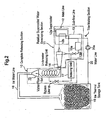
- the system comprises an ice thermal storage tank 19 for storing the ice produced in the system, a residual supercooled water developing section 11 in which the water supplied from the ice thermal storage tank 19 is supercooled and residual supercooled water is caused to be developed when ice is generated by underwater supercooling release of said supercooled water, a complete releasing section 10 for effecting complete releasing of the residual supercooled water, an ice water line 18 which connects said complete releasing section 10 to said ice thermal storage tank 19, and a water line 20 which connects the ice thermal storage tank 19 to the residual supercooled water developing section 11 and is equipped with a pump 20a.
- ice making section 1 indicates constituent elements other than the ice thermal storage tank 19.
- the residual supercooled water developing section 11 includes a main line 12, an underwater releasing unit 14, and a sub-flow line 13.
- Water to be supercooled is supplied from the ice thermal storage tank 19 to the main line 12 by the pump 20a through the water line 20 which is provided with a preheater(not shown in the drawing) for melting the ice mixing in the water.
- the water to be supercooled is introduced into a supercooler 12a with solid matter mixing in the water removed through a filter (not shown in the drawing) and supercooled water is generated therein.
- the supercooled water is sent through a main flow passage 12b to the underwater releasing unit 14 where underwater supercooling release of the supercooled water is performed.
- the underwater releasing unit 14 is a closed vessel. It receives the supercooled water from the main line 12 and also receives sub-flow water containing seed ice from the sub-flow line 13 having a seed ice generating section 13a and a sub-flow passage 13b to achieve underwater supercooling release of the supercooled water.
- the residual mixture which contains residual supercooled water not completely released and ice generated by supercooling release, is sent to the complete releasing section 10.
- the complete releasing section 10 is provided between the underwater releasing unit 14 and the ice thermal storage tank 19 via a ice water line 18.
- the complete releasing section 10 comprises a vortex type supercooling releaser 15, an inducing unit 17, and a bypass line 16.
- the vortex type supercooling releaser 15 is composed of an erect, cylindrical container 15b having an upper conical part 15a provided with an outlet and air bleeder and provided with an inlet directed tangential to the circumference in its bottom portion 15c.
- a nozzle 14a which forms outlet of the horizontally located underwater releasing unit 14 is connected to said inlet. From the nozzle 14a is spouted the residual mixture mentioned above.
- a spiral flow is generated in the erect, cylindrical container 15b by said spout and vortex flow 15d is formed.
- the introduced residual mixture of residual supercooled water and ice nuclei is agitated by the vortex flow 15d, and the nuclei of which the density is smaller than the supercooled water gather toward the center of the cylindrical container and form an ascending vortex flow.
- the residual supercooled water contacts frequently with the nuclei in said process, and if some nuclei adhere to the wall surface, they are not consolidated thereon but separated therefrom because of the large sectional area of flow and considerable high flow velocity near the wall surface owing to the vortex flow. Therefore, the supercooling release of the residual supercooled water in the mixture can be effected.
- the upper conical part 15a is shaped conical so that the vortex flow continues to the upper portion.
- the velocity of ascending of the nuclei by the vortex flow 15d can be determined by the velocity of the flow from the nozzle 14a of the underwater releasing unit 14 and the sectional area of the cylindrical container, but also the residence period from the time the nuclei entered at the inlet reach the outlet in the upper portion can be determined so that it complies with the rate of supercooling of the residual supercooledwater, that means the residence period can be uniquely determined.
- the inducing unit 17 is supplied with apart of the supercooled water from the vortex type releasing section 15 through the bypass line 16. Ice nuclei are generated in said inducing unit 17 and the ice nuclei are circulated to the underwater releasing unit 14 together with the supercooled water.
- the releasing of supercooling is enhanced and fluctuation in the rate of supercooling is dealt with.
- the inducing unit 17 comprises a throttle valve 17b, an electromagnetic valve 17a, a flow passage connecting said valves in parallel, and a feed pump 17c.
- Inducing is done depending on the water temperature at the outlet of the supercooler 12a by directly measuring it.
- predetermined temperature for example, a temperature lower than about 0.3 °C
- the flow in the sub-flow line 13 is shut down, bypass line 16 is opened, and feed pump 17c is activated.
- the supercooled water is bypassed through the bypass line 16 to be flowed into the underwater releasing unit 14.
- supercooling release can not be induced by the activation of the pump 17c only.
- said electromagnetic valve 17a is activated to reiterate opening and closing with a predetermined period(constant period) for supercooling releasing.
- the flow rate through the throttle valve 17b which is adjusted by the opening of the valve, is rapidly varied every time the valve is opened and closed, so large, rapidpressure fluctuation is generated in the inlet side of the feed pump. 17c.
- the supercooled state is released and ice nuclei are generated.
- the generated nuclei are supplied to the underwater releasing unit 14 to effect releasing of supercooled state in the underwater releasing unit 14.
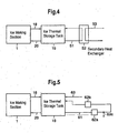
- the low temperature water supply system shown in FIG. 4 is a so-called closed cycle system.
- the system comprises the ice making system having the ice making section 1 and ice thermal storage tank 19 explained in FIG. 2 .
- a secondary heat exchanger 52 is connected to the ice thermal storage tank 19 via a circulation line 51.
- a circulation pump(not shown in the drawing) is provided in the circulation line 51.
- a load line 53 which is connected, for example, to factories and buildings, etc., and heat exchange is done between the circulation line 51 and load line 53 by the medium of the secondary heat exchanger 52, as mentioned later.
- the ice water generated in the ice making section 1 is, as explained in FIG. 2 , stored in the ice thermal storage tank 19 and at the same time supplied to the ice making section 1 through the water line 20.
- the cold water(ice water) stored in the ice thermal storage tank 19 is supplied to the secondary heat exchanger 52 by the circulation pump through the circulation line 51.
- cooling medium such as water, air, and water solution, for example
- the cooled load is sent to factories or buildings and used for air-conditioning, refrigeration, etc. through the medium, for example, of heat exchanger(not shown in the drawing) located in the factories or buildings, etc.
- the ice thermal storage tank 19 is not influenced by the variations of flow rate, etc. in the secondary side(load side).
- a low temperature water supply system can easily be constructed only by connecting the load line 53 and circulation line 51 to the secondary heat exchanger 52.
- the closed cycle system is suited in the case where it is not suitable to send the cold water in the ice thermal storage tank directly to the load side medium because of the possibility of leakage of the cold water to the load side medium, especially when an addition agent is added to the water in the ice thermal storage tank.
- the low temperature water supply system shown in FIG. 5 is a so-called open cycle system.
- the system comprises the ice making system having the ice making section 1 and ice thermal storage tank 19 explained in FIG.2 .
- a supply line 61 is connected to the ice thermal storage tank 19.
- To the supply line 61 are connected heat exchangers 62a and 62b located, for example, in factories or buildings, etc.
- the supply line 61 also provided with a cold water supply part 62c.
- heat exchangers 62a and 62b are shown in FIG. 5 , it is suitable to provide more than one heat exchanger as necessary. Also more than one cold water supply part 62c may be provided as necessary.
- the ice water generated in the ice making section 1 is, as explained in FIG. 2 , stored in the ice thermal storage tank 19 and supplied at the same time to the ice making section 1 through the water line 20.
- the cold water(ice water) stored in the ice thermal storage tank 19 is supplied by the circulation pump through the supply line 61 to the heat exchangers 62a and 62b, where heat exchange is achieved between the cold water and the load( cooling medium such as water, air, and water solution, for example), and air conditioning, refrigeration, etc. are performed by the cooling medium.
- cold water can be supplied directly to factories or buildings to be directly utilized therein.
- a water supply line(water supply system) 63 is connected to the ice thermal storage tank 19 and water is supplied to the ice thermal storage tank 19 through the water supply line 63 to compensate the decrease of the cold water.
- the secondary heat exchanger is not needed, so that not only thermal efficiency is increased but direct utilization of cold water is possible in the secondary side (load side) of factories or buildings, etc.
- the present invention when the water or water solution in a ice thermal storage tank is supercooled through a supercooler and the supercooled water is accommodated in a vessel to be released from the supercooled state continuously under water for making ice, clogging of the downstream flow passage caused by residual supercooled water can be prevented by achieving complete supercooling release reliably without leaving supercooled water. Further, by using the ice making system according to the present invention, easy construction of low temperature water supply system is possible.
Landscapes
- Engineering & Computer Science (AREA)
- Physics & Mathematics (AREA)
- Mechanical Engineering (AREA)
- Thermal Sciences (AREA)
- General Engineering & Computer Science (AREA)
- Other Air-Conditioning Systems (AREA)
- Production, Working, Storing, Or Distribution Of Ice (AREA)
- Devices That Are Associated With Refrigeration Equipment (AREA)
Abstract
Description
- The present invention relates to a system for making ice by releasing continuously under water the supercooled state of supercooled water and a low temperature water supply system comprising said ice making system.
- Generally, when making ice by underwater supercooling release, if a so-called residual supercooled state exists in which ice is mingled in supercooled water and the residual supercooled state is transferred downstream while kept in the supercooled state, ice adheres to the wall of the flow channel extending downstream from a supercooling releasing section to an ice thermal storage tank, and it may happen that the flow channel is clogged due to the growth of the adhered ice.
- That is, the growth of the ice adhered to the wall of the flow channel is fostered by the contact with the ambient supercooled water.
- As the adhesion of the ice crystal grown on the wall where the flow velocity is small is strong and the adhered ice is difficult to be separated, ice adheres all over the wall and the flow channel becomes narrowed if such a state continues for a long period.
- Further, significantly high pressure is needed to separate the ice grown on the wall, and in addition, sherbet-like ice becomes consolidated due to the force of flow resistance, and finally the pipe conduit(flow channel) may be completely clogged. Therefore, when making ice by underwater supercooling release, it is necessary to prevent the clogging in the downstream pipe conduit by releasing residual supercooled state.
- A method of releasing residual supercooled state is disclosed, for example, in Japanese Patent Application Publication No.
5-149653 - In the example of prior art, as shown in
FIG. 1 , a completing section of supercooling release is provided downstream after supercooling is released. For example, inFIG.1(a) , athrottling section 110 is provided downstream of a underwatersupercooling releasing section 108, further anenlargement section 109a and atapered section 109b for throttling the flow area to that of thethrottling section 110 are provided downstream of thethrottling section 110. Thethrottling section 110,enlargement section 109a, andtapered section 109b compose the completion section of supercooling release. - In the completion section of supercooling release shown in
FIG. 1(a) , complete release of supercooling is enhanced by the agitation generated as a result of abrupt enlargement of water flow section area after the water passes through the supercooling releasing section. - In the completion section of supercooling release shown in
FIG.1(b) , a plurality of enlargement section 109a1 and 109a2 are provided after thethrottling section 110. In the completion section of supercooling release shown inFIG. 1(c) , animpingement member 109c is located in the center of theenlargement section 109a for generating a turbulent flow. - As described above, in the example of prior art, a turbulent flow is generated in the downstream flow channel to release the residual supercooled state by the agitation induced by the turbulence.
- However, it is necessary, in the example of prior art, to provide at least a throttling section, enlargement section, and tapered section. As a result, a problem is encountered that not only the downstream piping must inevitably be long but the ice making apparatus becomes large and complicated.
- Further, in the example of prior art, the residual supercooled state is released only by the agitation induced by flow turbulence, so that the residual supercooled state can not be released enough and as a result clogging may occur in the pipe conduit.
-
JP-A 06-074498 claim 1. Another prior-art ice making system is known fromJP-A 07-004801 - An object of the present invention is to provide a system of making ice by underwater supercooling release capable of preventing the clogging in pipe conduit through releasing the residual supercooled state with a compact construction.
- This object is met by the system defined in
claim 1. - The present invention further provides low temperature water supply systems comprising an ice making system in accordance with claims 6 and 7.
-
-
FIG. 1 is a representation for explaining the construction of the complete releasing section of supercooling used in a ice making system of prior art. -
FIG.2 is a representation showing an example of the ice making system of the present invention. -
FIG. 3 is a representation for explaining the construction of the inducing unit shown inFIG.2 . -
FIG.4 is a representation showing an example of the low temperature water supply system using the ice making system shown inFIG.2 . -
FIG.5 is a representation showing another example of the low temperature water supply system using the ice making system shown inFIG.2 . - A preferred embodiment of the present invention will now be detailed with reference to the accompanying drawings. It is intended, however, that unless particularly specified, dimensions, materials, relative positions and so forth of the constituent parts in the embodiments shall be interpreted as illustrative only not as limitative of the scope of the present invention.
- Referring to
FIG. 2 , the ice making system employs underwater supercooling release. The system comprises an icethermal storage tank 19 for storing the ice produced in the system, a residual supercooledwater developing section 11 in which the water supplied from the icethermal storage tank 19 is supercooled and residual supercooled water is caused to be developed when ice is generated by underwater supercooling release of said supercooled water, a complete releasingsection 10 for effecting complete releasing of the residual supercooled water, anice water line 18 which connects said complete releasingsection 10 to said icethermal storage tank 19, and awater line 20 which connects the icethermal storage tank 19 to the residual supercooledwater developing section 11 and is equipped with apump 20a. In the drawing,ice making section 1 indicates constituent elements other than the icethermal storage tank 19. - The residual supercooled
water developing section 11 includes amain line 12, an underwater releasingunit 14, and asub-flow line 13. Water to be supercooled is supplied from the icethermal storage tank 19 to themain line 12 by thepump 20a through thewater line 20 which is provided with a preheater(not shown in the drawing) for melting the ice mixing in the water. In themain line 12, the water to be supercooled is introduced into asupercooler 12a with solid matter mixing in the water removed through a filter ( not shown in the drawing) and supercooled water is generated therein. The supercooled water is sent through amain flow passage 12b to theunderwater releasing unit 14 where underwater supercooling release of the supercooled water is performed. - The
underwater releasing unit 14 is a closed vessel. It receives the supercooled water from themain line 12 and also receives sub-flow water containing seed ice from thesub-flow line 13 having a seedice generating section 13a and asub-flow passage 13b to achieve underwater supercooling release of the supercooled water. The residual mixture, which contains residual supercooled water not completely released and ice generated by supercooling release, is sent to the complete releasingsection 10. - By the way, if the residual supercooled water not completely released is supplied from the
underwater releasing unit 14 directly to the icethermal storage tank 19, it may happen that ice adheres to the wall of the flow passage downstream of theunderwater releasing unit 14 toward the icethermal storage tank 19 and the downstream passage is clogged by the growth of adhered ice. Further, if residual supercooled water maintaining supercooled state is returned to the icethermal storage tank 19 and reflowed again to theheat exchanger 12a for generating supercooled water, freezing may happen in the heat exchanger. - The complete releasing
section 10 is provided between theunderwater releasing unit 14 and the icethermal storage tank 19 via aice water line 18. - As shown in
FIG. 2 andFIG. 3 , the complete releasingsection 10 comprises a vortextype supercooling releaser 15, aninducing unit 17, and abypass line 16. - Referring to
FIG. 3 , the vortextype supercooling releaser 15 is composed of an erect,cylindrical container 15b having an upperconical part 15a provided with an outlet and air bleeder and provided with an inlet directed tangential to the circumference in itsbottom portion 15c. - A
nozzle 14a which forms outlet of the horizontally located underwater releasingunit 14 is connected to said inlet. From thenozzle 14a is spouted the residual mixture mentioned above. - A spiral flow is generated in the erect,
cylindrical container 15b by said spout andvortex flow 15d is formed. - The introduced residual mixture of residual supercooled water and ice nuclei is agitated by the
vortex flow 15d, and the nuclei of which the density is smaller than the supercooled water gather toward the center of the cylindrical container and form an ascending vortex flow. - The residual supercooled water contacts frequently with the nuclei in said process, and if some nuclei adhere to the wall surface, they are not consolidated thereon but separated therefrom because of the large sectional area of flow and considerable high flow velocity near the wall surface owing to the vortex flow. Therefore, the supercooling release of the residual supercooled water in the mixture can be effected.
- At the time when the nuclei reach the outlet in the upper portion, the supercooled water accompanying the nuclei is completely released from supercooled state.
- The upper
conical part 15a is shaped conical so that the vortex flow continues to the upper portion. - According to the construction as mentioned above, not only the velocity of ascending of the nuclei by the
vortex flow 15d can be determined by the velocity of the flow from thenozzle 14a of theunderwater releasing unit 14 and the sectional area of the cylindrical container, but also the residence period from the time the nuclei entered at the inlet reach the outlet in the upper portion can be determined so that it complies with the rate of supercooling of the residual supercooledwater, that means the residence period can be uniquely determined. - After the manner like this, complete releasing of residual supercooled water can be achieved by providing an erect, cylindrical container of suitable dimensions.
- The inducing
unit 17 is supplied with apart of the supercooled water from the vortextype releasing section 15 through thebypass line 16. Ice nuclei are generated in said inducingunit 17 and the ice nuclei are circulated to theunderwater releasing unit 14 together with the supercooled water. Herewith, the releasing of supercooling is enhanced and fluctuation in the rate of supercooling is dealt with. - As shown in the drawings, the
inducing unit 17 comprises athrottle valve 17b, anelectromagnetic valve 17a, a flow passage connecting said valves in parallel, and afeed pump 17c. - Inducing is done depending on the water temperature at the outlet of the
supercooler 12a by directly measuring it. When predetermined temperature(for example, a temperature lower than about 0.3 °C) is detected, the flow in thesub-flow line 13 is shut down,bypass line 16 is opened, andfeed pump 17c is activated. Herewith, the supercooled water is bypassed through thebypass line 16 to be flowed into the underwater releasingunit 14. However, supercooling release can not be induced by the activation of thepump 17c only. In this case, saidelectromagnetic valve 17a is activated to reiterate opening and closing with a predetermined period(constant period) for supercooling releasing. Through this operation, the flow rate through thethrottle valve 17b, which is adjusted by the opening of the valve, is rapidly varied every time the valve is opened and closed, so large, rapidpressure fluctuation is generated in the inlet side of the feed pump. 17c. As a result, the supercooled state is released and ice nuclei are generated. The generated nuclei are supplied to the underwater releasingunit 14 to effect releasing of supercooled state in the underwater releasingunit 14. - When a part of the supercooled state is released, supercooling releasing proceeds with adhered or separated ice as seed ice, so that further inducing of supercooling release is not necessary. Therefore, after finishing inducement, the
bypass line 16 is shut down and cold water is supplied to thesub-flow line 13 from the icethermal storage tank 19. - With the ice making system described above, complete releasing of residual supercooled water after underwater supercooling release can be achieved, so freezing and clogging of flow passage in the process of transfer of supercooled water to the ice thermal storage tank can be prevented, and also freezing and clogging in the flow passage from the ice thermal storage tank to the supercooler, particularly in the pipe coduit in the supercooler can be prevented because there exists no residual supercooled water in the ice thermal storage tank due to said complete supercooling release.
- Complete releasing of residual supercooled water accompanying ice nuclei can be achieved in the erect, cylindrical container, in which supercooling release is enhanced through the increase of contact of the supercooled water with ice nuclei owing to vortex flow or spiraling flow , and even if generated ice nuclei adhere to the wall, they are not consolidated but separated from the wall and gather toward the center of the spiraling flow because of the large sectional area of the flow and large flow velocity near the wall owing to the vortex flow.
- Furthermore, by providing the inducing unit, not only the supercooling release in the underwater releasing unit is enhanced but also the variation in the rate of supercooling can be dealt with.
- Thus, with the ice making system, residual supercooled state can be released and the clogging in pipe conduit can be prevented with simple construction.
- Next, with reference to
FIG.4 , an example of the low temperature supply system using said ice making system will be explained. - The low temperature water supply system shown in
FIG. 4 is a so-called closed cycle system. The system comprises the ice making system having theice making section 1 and icethermal storage tank 19 explained inFIG. 2 . Asecondary heat exchanger 52 is connected to the icethermal storage tank 19 via acirculation line 51. A circulation pump(not shown in the drawing) is provided in thecirculation line 51. - To the
secondary heat exchanger 52 is connected aload line 53 which is connected, for example, to factories and buildings, etc., and heat exchange is done between thecirculation line 51 andload line 53 by the medium of thesecondary heat exchanger 52, as mentioned later. - The ice water generated in the
ice making section 1 is, as explained inFIG. 2 , stored in the icethermal storage tank 19 and at the same time supplied to theice making section 1 through thewater line 20. On the other hand, the cold water(ice water) stored in the icethermal storage tank 19 is supplied to thesecondary heat exchanger 52 by the circulation pump through thecirculation line 51. - The load from factories, buildings, etc. in the shape of cooling medium such as water, air, and water solution, for example, is supplied to the
secondary heat exchanger 52 through theload line 53. In thesecondary heat exchanger 52, heat exchange is achieved between the cold water and load. As a result, the cold water is heated and the load is cooled. The heated cold water is again returned to the icethermal storage tank 19 to be cooled. - On the other hand, the cooled load is sent to factories or buildings and used for air-conditioning, refrigeration, etc. through the medium, for example, of heat exchanger(not shown in the drawing) located in the factories or buildings, etc.
- With the closed cycle system as mentioned above, the ice
thermal storage tank 19 is not influenced by the variations of flow rate, etc. in the secondary side(load side). - The reason is that the condition of suction, etc. from the ice
thermal storage tank 19 is constant, for the amount of water, etc in the icethermal storage tank 19 does not change. - By unifying the
ice making section 1 and icethermal storage tank 19 in a unit, a low temperature water supply system can easily be constructed only by connecting theload line 53 andcirculation line 51 to thesecondary heat exchanger 52. - As a result, not only the construction time is shortened but also the renewal of the system is easy.
- Further, the closed cycle system is suited in the case where it is not suitable to send the cold water in the ice thermal storage tank directly to the load side medium because of the possibility of leakage of the cold water to the load side medium, especially when an addition agent is added to the water in the ice thermal storage tank.
- Next, with reference to
FIG.5 , another example of low temperature water supply system using said ice making system will be explained. - The low temperature water supply system shown in
FIG. 5 is a so-called open cycle system. The system comprises the ice making system having theice making section 1 and icethermal storage tank 19 explained inFIG.2 . Asupply line 61 is connected to the icethermal storage tank 19. To thesupply line 61 are connectedheat exchangers supply line 61 also provided with a coldwater supply part 62c. - Although two
heat exchangers FIG. 5 , it is suitable to provide more than one heat exchanger as necessary. Also more than one coldwater supply part 62c may be provided as necessary. - The ice water generated in the
ice making section 1 is, as explained inFIG. 2 , stored in the icethermal storage tank 19 and supplied at the same time to theice making section 1 through thewater line 20. On the other hand, the cold water(ice water) stored in the icethermal storage tank 19 is supplied by the circulation pump through thesupply line 61 to theheat exchangers - When said direct utilization of the cold water is done, the cold water stored in the ice
thermal storage tank 19 decreases. Therefore, a water supply line(water supply system) 63 is connected to the icethermal storage tank 19 and water is supplied to the icethermal storage tank 19 through thewater supply line 63 to compensate the decrease of the cold water. - In the case of the open cycle as mentioned above, the secondary heat exchanger is not needed, so that not only thermal efficiency is increased but direct utilization of cold water is possible in the secondary side (load side) of factories or buildings, etc.
- As has been described in the foregoing, according to the present invention, when the water or water solution in a ice thermal storage tank is supercooled through a supercooler and the supercooled water is accommodated in a vessel to be released from the supercooled state continuously under water for making ice, clogging of the downstream flow passage caused by residual supercooled water can be prevented by achieving complete supercooling release reliably without leaving supercooled water. Further, by using the ice making system according to the present invention, easy construction of low temperature water supply system is possible.
Claims (7)
- A system for making ice by underwater supercooling release, comprising:a closed vessel (14);a supercooler (12a) for supplying supercooled water to the vessel (14);a sub-flow line (13) for supplying sub-flow water containing seed ice to said vessel (14) and releasing the supercooled state of said supercooled water under water;an erect cylindrical container (15b);an inlet provided at the bottom part of the container (15b) for supplying the mixture from said vessel (14) containing residual supercooled water and generated ice nuclei with predetermined velocity in a direction tangential to the circumference of the container (15a) to generate a spiraling flow (15d) therein; andan outlet (15a), which also serves as air bleeder, in the upper portion of the container (15b) for discharging ice nuclei,characterised in that the outlet (15a) is conically shaped.
- The system of claim 1, wherein the volume of the container (15b) is variable in accordance with the rate of supercooling of said residual supercooled water.
- The system of claim 1, comprising a bypass passage (16) provided between said container (15b) and said closed vessel (14), and an inducing mechanism (17) located in said bypass passage (16) for enhancing supercooling release.
- The system of claim 3, wherein said inducing mechanism (17) is provided with an automatic throttle valve mechanism (17b) for generating rapid pressure fluctuation of the supercooled water circulated through said bypass passage (16).
- The system of any preceding claim, comprising an ice thermal storage tank (19) for storing said generated ice.
- A low temperature water supply system comprising
the ice making system of claim 5;
a circulation line (15) connected to said ice thermal storage tank (19) for circulating water; and
a secondary heat exchanger (52) connected to the circulation line (15). - A low temperature water supply system comprising
the ice making system of claim 5;
a cold water feed line (61) connected to said ice thermal storage tank (19); and
a water supply mechanism (63) for supplying water to said ice thermal storage tank (19).
Applications Claiming Priority (3)
| Application Number | Priority Date | Filing Date | Title |
|---|---|---|---|
| JP2001294346A JP3949917B2 (en) | 2001-09-26 | 2001-09-26 | Ice making method and ice making device by releasing subcooling in water |
| JP2001294346 | 2001-09-26 | ||
| PCT/JP2002/003429 WO2003031887A1 (en) | 2001-09-26 | 2002-04-05 | Method and system for making ice by underwater supercooling release and low temperature water supply system comprising it |
Publications (3)
| Publication Number | Publication Date |
|---|---|
| EP1431685A1 EP1431685A1 (en) | 2004-06-23 |
| EP1431685A4 EP1431685A4 (en) | 2009-06-03 |
| EP1431685B1 true EP1431685B1 (en) | 2010-10-27 |
Family
ID=19115970
Family Applications (1)
| Application Number | Title | Priority Date | Filing Date |
|---|---|---|---|
| EP02713298A Expired - Lifetime EP1431685B1 (en) | 2001-09-26 | 2002-04-05 | System for making ice by underwater supercooling release and low temperature water supply system comprising it |
Country Status (9)
| Country | Link |
|---|---|
| US (1) | US6915643B2 (en) |
| EP (1) | EP1431685B1 (en) |
| JP (1) | JP3949917B2 (en) |
| KR (1) | KR100774604B1 (en) |
| AT (1) | ATE486255T1 (en) |
| CA (1) | CA2461211C (en) |
| DE (1) | DE60238130D1 (en) |
| ES (1) | ES2352663T3 (en) |
| WO (1) | WO2003031887A1 (en) |
Families Citing this family (11)
| Publication number | Priority date | Publication date | Assignee | Title |
|---|---|---|---|---|
| GB2385120B (en) * | 2002-02-09 | 2004-05-19 | Thermetica Ltd | Thermal storage apparatus |
| FR2864794B1 (en) * | 2004-01-06 | 2006-05-19 | Centre Nat Rech Scient | CONTINUOUS PROCESS FOR PARTIALLY CRYSTALLIZING A SOLUTION AND DEVICE FOR IMPLEMENTING THE SAME |
| US7861551B2 (en) | 2007-11-30 | 2011-01-04 | Whirlpool Corporation | Method and device for producing ice droplets on demand |
| AU2011343814B2 (en) * | 2010-12-17 | 2015-06-18 | Kerry R. Seymour | Ice and chilled water producing and dispensing machine |
| EP2990742A1 (en) | 2014-08-28 | 2016-03-02 | ABB Technology AG | Method and apparatus for solidifying a polar substance |
| CN106152340A (en) * | 2015-04-28 | 2016-11-23 | 深圳市绿旭节能有限公司 | Closed type supercooling release device |
| JP6712200B2 (en) * | 2016-08-25 | 2020-06-17 | 大陽日酸株式会社 | Slurry ice manufacturing method |
| CN107062723A (en) * | 2017-05-19 | 2017-08-18 | 浙江海洋大学 | A kind of utilization ultrasonic wave promotes the devices and methods therefor of seawater fluidisation ice nucleation |
| CN107941450B (en) * | 2017-09-20 | 2023-11-03 | 中国空气动力研究与发展中心低速空气动力研究所 | Jet angle vortex generator for inhibiting low-frequency pressure pulsation of open jet wind tunnel |
| US11053112B2 (en) | 2019-07-08 | 2021-07-06 | Kooler Ice, Inc. | Systems for producing and dispensing chilled water |
| CN112178996A (en) * | 2020-08-31 | 2021-01-05 | 天津职业技术师范大学(中国职业培训指导教师进修中心) | Method for quickly making ice and ice making device |
Family Cites Families (11)
| Publication number | Priority date | Publication date | Assignee | Title |
|---|---|---|---|---|
| US4261182A (en) * | 1978-10-05 | 1981-04-14 | General Electric Company | Automatic icemaker including means for minimizing the supercooling effect |
| JP3115026B2 (en) * | 1991-06-03 | 2000-12-04 | 株式会社サンウェル・ジャパン | Ice separator |
| JP2946889B2 (en) * | 1991-11-27 | 1999-09-06 | ダイキン工業株式会社 | Ice making equipment |
| JPH0674498A (en) | 1992-07-10 | 1994-03-15 | Daikin Ind Ltd | Ice making device |
| JP2811271B2 (en) | 1993-06-18 | 1998-10-15 | 新菱冷熱工業株式会社 | Ice making equipment |
| US5931003A (en) * | 1995-09-01 | 1999-08-03 | Natron Corporation | Method and system for electronically controlling the location of the formation of ice within a closed loop water circulating unit |
| US5653114A (en) * | 1995-09-01 | 1997-08-05 | Nartron Corporation | Method and system for electronically controlling the location of the formation of ice within a closed loop water circulating unit |
| JPH09303832A (en) * | 1996-05-14 | 1997-11-28 | Daikin Ind Ltd | Ice making equipment |
| US5829257A (en) * | 1997-03-31 | 1998-11-03 | Narton Corporation | Methods and systems for harvesting ice in an ice making apparatus |
| JPH11236295A (en) * | 1998-02-23 | 1999-08-31 | Kansai Electric Power Co Inc:The | Single crystal production method, single crystal ice production method, single crystal ice crystal orientation control method, single crystal ice production apparatus, and ice skating rink technology using single crystal ice |
| JP4236232B2 (en) * | 1999-04-28 | 2009-03-11 | 株式会社前川製作所 | Ice slurry surface processing method and apparatus |
-
2001
- 2001-09-26 JP JP2001294346A patent/JP3949917B2/en not_active Expired - Fee Related
-
2002
- 2002-04-05 KR KR1020047004391A patent/KR100774604B1/en not_active Expired - Fee Related
- 2002-04-05 CA CA002461211A patent/CA2461211C/en not_active Expired - Fee Related
- 2002-04-05 EP EP02713298A patent/EP1431685B1/en not_active Expired - Lifetime
- 2002-04-05 WO PCT/JP2002/003429 patent/WO2003031887A1/en not_active Ceased
- 2002-04-05 ES ES02713298T patent/ES2352663T3/en not_active Expired - Lifetime
- 2002-04-05 DE DE60238130T patent/DE60238130D1/en not_active Expired - Lifetime
- 2002-04-05 US US10/490,612 patent/US6915643B2/en not_active Expired - Lifetime
- 2002-04-05 AT AT02713298T patent/ATE486255T1/en not_active IP Right Cessation
Also Published As
| Publication number | Publication date |
|---|---|
| JP2003106715A (en) | 2003-04-09 |
| CA2461211A1 (en) | 2003-04-17 |
| CA2461211C (en) | 2005-06-14 |
| JP3949917B2 (en) | 2007-07-25 |
| KR20040054696A (en) | 2004-06-25 |
| KR100774604B1 (en) | 2007-11-09 |
| WO2003031887A1 (en) | 2003-04-17 |
| ES2352663T3 (en) | 2011-02-22 |
| ATE486255T1 (en) | 2010-11-15 |
| US20040231343A1 (en) | 2004-11-25 |
| EP1431685A1 (en) | 2004-06-23 |
| DE60238130D1 (en) | 2010-12-09 |
| EP1431685A4 (en) | 2009-06-03 |
| US6915643B2 (en) | 2005-07-12 |
Similar Documents
| Publication | Publication Date | Title |
|---|---|---|
| US6915643B2 (en) | Method and system for making ice by underwater supercooling release and low temperature water supply system comprising it | |
| EP1476707B1 (en) | Thermal storage apparatus | |
| US4401449A (en) | Slush ice maker | |
| RU2403187C2 (en) | Modular refrigerating system and refrigerator for this system | |
| KR102188286B1 (en) | Chiller control apparatus for semiconductor process | |
| CN111316046A (en) | Liquid temperature control device and temperature control method using same | |
| US4226364A (en) | Single conduit air conditioning system | |
| JP2006084047A (en) | Heat exchanger | |
| CN104582921B (en) | Apparatus and method for tempering an object | |
| JP2003056951A (en) | Ice slurry continuous ice making method and its continuous ice heat storage system | |
| JPH05296622A (en) | Ice maker | |
| JPH10325657A (en) | Ice storage device | |
| JP3516314B2 (en) | Ice heat storage device using supercooled water | |
| JPH0285627A (en) | Secondary side system in cooling method using water containing ice | |
| JPH04306471A (en) | Ice heat accumulating device | |
| JPH01266455A (en) | Cooling device using ice water | |
| JPH08233417A (en) | Method for determining abnormality of heat exchanger in circulating chiller | |
| JPH04263724A (en) | Ice heat accumulator | |
| JP3006138B2 (en) | Ice making equipment | |
| JPH04263721A (en) | Ice heat accumulator | |
| JPH11337133A (en) | Dynamic ice thermal storage device | |
| JPH05322395A (en) | Ice heat storage device | |
| JP3331003B2 (en) | Ice storage method for multiple tanks in ice thermal storage system | |
| JPH04270833A (en) | Ice heat accumulating device | |
| JP3671077B2 (en) | Refrigerant circulation device for indoor unit of ice heat storage system |
Legal Events
| Date | Code | Title | Description |
|---|---|---|---|
| PUAI | Public reference made under article 153(3) epc to a published international application that has entered the european phase |
Free format text: ORIGINAL CODE: 0009012 |
|
| 17P | Request for examination filed |
Effective date: 20040415 |
|
| AK | Designated contracting states |
Kind code of ref document: A1 Designated state(s): AT BE CH CY DE DK ES FI FR GB GR IE IT LI LU MC NL PT SE TR |
|
| A4 | Supplementary search report drawn up and despatched |
Effective date: 20090507 |
|
| 17Q | First examination report despatched |
Effective date: 20090909 |
|
| GRAP | Despatch of communication of intention to grant a patent |
Free format text: ORIGINAL CODE: EPIDOSNIGR1 |
|
| RTI1 | Title (correction) |
Free format text: SYSTEM FOR MAKING ICE BY UNDERWATER SUPERCOOLING RELEASE AND LOW TEMPERATURE WATER SUPPLY SYSTEM COMPRISING IT |
|
| GRAS | Grant fee paid |
Free format text: ORIGINAL CODE: EPIDOSNIGR3 |
|
| GRAA | (expected) grant |
Free format text: ORIGINAL CODE: 0009210 |
|
| AK | Designated contracting states |
Kind code of ref document: B1 Designated state(s): AT BE CH CY DE DK ES FI FR GB GR IE IT LI LU MC NL PT SE TR |
|
| REG | Reference to a national code |
Ref country code: GB Ref legal event code: FG4D |
|
| REG | Reference to a national code |
Ref country code: CH Ref legal event code: EP |
|
| REG | Reference to a national code |
Ref country code: IE Ref legal event code: FG4D |
|
| REF | Corresponds to: |
Ref document number: 60238130 Country of ref document: DE Date of ref document: 20101209 Kind code of ref document: P |
|
| REG | Reference to a national code |
Ref country code: NL Ref legal event code: T3 |
|
| REG | Reference to a national code |
Ref country code: ES Ref legal event code: FG2A Effective date: 20110210 |
|
| PG25 | Lapsed in a contracting state [announced via postgrant information from national office to epo] |
Ref country code: PT Free format text: LAPSE BECAUSE OF FAILURE TO SUBMIT A TRANSLATION OF THE DESCRIPTION OR TO PAY THE FEE WITHIN THE PRESCRIBED TIME-LIMIT Effective date: 20110228 Ref country code: AT Free format text: LAPSE BECAUSE OF FAILURE TO SUBMIT A TRANSLATION OF THE DESCRIPTION OR TO PAY THE FEE WITHIN THE PRESCRIBED TIME-LIMIT Effective date: 20101027 Ref country code: SE Free format text: LAPSE BECAUSE OF FAILURE TO SUBMIT A TRANSLATION OF THE DESCRIPTION OR TO PAY THE FEE WITHIN THE PRESCRIBED TIME-LIMIT Effective date: 20101027 Ref country code: FI Free format text: LAPSE BECAUSE OF FAILURE TO SUBMIT A TRANSLATION OF THE DESCRIPTION OR TO PAY THE FEE WITHIN THE PRESCRIBED TIME-LIMIT Effective date: 20101027 |
|
| PG25 | Lapsed in a contracting state [announced via postgrant information from national office to epo] |
Ref country code: BE Free format text: LAPSE BECAUSE OF FAILURE TO SUBMIT A TRANSLATION OF THE DESCRIPTION OR TO PAY THE FEE WITHIN THE PRESCRIBED TIME-LIMIT Effective date: 20101027 Ref country code: GR Free format text: LAPSE BECAUSE OF FAILURE TO SUBMIT A TRANSLATION OF THE DESCRIPTION OR TO PAY THE FEE WITHIN THE PRESCRIBED TIME-LIMIT Effective date: 20110128 |
|
| PG25 | Lapsed in a contracting state [announced via postgrant information from national office to epo] |
Ref country code: DK Free format text: LAPSE BECAUSE OF FAILURE TO SUBMIT A TRANSLATION OF THE DESCRIPTION OR TO PAY THE FEE WITHIN THE PRESCRIBED TIME-LIMIT Effective date: 20101027 |
|
| PLBE | No opposition filed within time limit |
Free format text: ORIGINAL CODE: 0009261 |
|
| STAA | Information on the status of an ep patent application or granted ep patent |
Free format text: STATUS: NO OPPOSITION FILED WITHIN TIME LIMIT |
|
| 26N | No opposition filed |
Effective date: 20110728 |
|
| REG | Reference to a national code |
Ref country code: DE Ref legal event code: R097 Ref document number: 60238130 Country of ref document: DE Effective date: 20110728 |
|
| PG25 | Lapsed in a contracting state [announced via postgrant information from national office to epo] |
Ref country code: MC Free format text: LAPSE BECAUSE OF NON-PAYMENT OF DUE FEES Effective date: 20110430 |
|
| REG | Reference to a national code |
Ref country code: CH Ref legal event code: PL |
|
| PG25 | Lapsed in a contracting state [announced via postgrant information from national office to epo] |
Ref country code: LI Free format text: LAPSE BECAUSE OF NON-PAYMENT OF DUE FEES Effective date: 20110430 Ref country code: CH Free format text: LAPSE BECAUSE OF NON-PAYMENT OF DUE FEES Effective date: 20110430 |
|
| REG | Reference to a national code |
Ref country code: IE Ref legal event code: MM4A |
|
| PG25 | Lapsed in a contracting state [announced via postgrant information from national office to epo] |
Ref country code: IE Free format text: LAPSE BECAUSE OF NON-PAYMENT OF DUE FEES Effective date: 20110405 |
|
| PG25 | Lapsed in a contracting state [announced via postgrant information from national office to epo] |
Ref country code: LU Free format text: LAPSE BECAUSE OF NON-PAYMENT OF DUE FEES Effective date: 20110405 Ref country code: CY Free format text: LAPSE BECAUSE OF FAILURE TO SUBMIT A TRANSLATION OF THE DESCRIPTION OR TO PAY THE FEE WITHIN THE PRESCRIBED TIME-LIMIT Effective date: 20101027 |
|
| PG25 | Lapsed in a contracting state [announced via postgrant information from national office to epo] |
Ref country code: TR Free format text: LAPSE BECAUSE OF FAILURE TO SUBMIT A TRANSLATION OF THE DESCRIPTION OR TO PAY THE FEE WITHIN THE PRESCRIBED TIME-LIMIT Effective date: 20101027 |
|
| REG | Reference to a national code |
Ref country code: FR Ref legal event code: PLFP Year of fee payment: 15 |
|
| REG | Reference to a national code |
Ref country code: FR Ref legal event code: PLFP Year of fee payment: 16 |
|
| REG | Reference to a national code |
Ref country code: FR Ref legal event code: PLFP Year of fee payment: 17 |
|
| PGFP | Annual fee paid to national office [announced via postgrant information from national office to epo] |
Ref country code: NL Payment date: 20180423 Year of fee payment: 17 |
|
| PGFP | Annual fee paid to national office [announced via postgrant information from national office to epo] |
Ref country code: DE Payment date: 20180508 Year of fee payment: 17 Ref country code: ES Payment date: 20180522 Year of fee payment: 17 |
|
| PGFP | Annual fee paid to national office [announced via postgrant information from national office to epo] |
Ref country code: FR Payment date: 20180426 Year of fee payment: 17 Ref country code: IT Payment date: 20180420 Year of fee payment: 17 |
|
| PGFP | Annual fee paid to national office [announced via postgrant information from national office to epo] |
Ref country code: GB Payment date: 20180427 Year of fee payment: 17 |
|
| REG | Reference to a national code |
Ref country code: DE Ref legal event code: R119 Ref document number: 60238130 Country of ref document: DE |
|
| REG | Reference to a national code |
Ref country code: NL Ref legal event code: MM Effective date: 20190501 |
|
| GBPC | Gb: european patent ceased through non-payment of renewal fee |
Effective date: 20190405 |
|
| PG25 | Lapsed in a contracting state [announced via postgrant information from national office to epo] |
Ref country code: NL Free format text: LAPSE BECAUSE OF NON-PAYMENT OF DUE FEES Effective date: 20190501 Ref country code: GB Free format text: LAPSE BECAUSE OF NON-PAYMENT OF DUE FEES Effective date: 20190405 Ref country code: DE Free format text: LAPSE BECAUSE OF NON-PAYMENT OF DUE FEES Effective date: 20191101 |
|
| PG25 | Lapsed in a contracting state [announced via postgrant information from national office to epo] |
Ref country code: FR Free format text: LAPSE BECAUSE OF NON-PAYMENT OF DUE FEES Effective date: 20190430 |
|
| PG25 | Lapsed in a contracting state [announced via postgrant information from national office to epo] |
Ref country code: IT Free format text: LAPSE BECAUSE OF NON-PAYMENT OF DUE FEES Effective date: 20190405 |
|
| REG | Reference to a national code |
Ref country code: ES Ref legal event code: FD2A Effective date: 20200828 |
|
| PG25 | Lapsed in a contracting state [announced via postgrant information from national office to epo] |
Ref country code: ES Free format text: LAPSE BECAUSE OF NON-PAYMENT OF DUE FEES Effective date: 20190406 |