EP1431594A2 - Kurbelwelle für eine Kolbenhubmaschine - Google Patents
Kurbelwelle für eine Kolbenhubmaschine Download PDFInfo
- Publication number
- EP1431594A2 EP1431594A2 EP03023914A EP03023914A EP1431594A2 EP 1431594 A2 EP1431594 A2 EP 1431594A2 EP 03023914 A EP03023914 A EP 03023914A EP 03023914 A EP03023914 A EP 03023914A EP 1431594 A2 EP1431594 A2 EP 1431594A2
- Authority
- EP
- European Patent Office
- Prior art keywords
- crank
- bearing element
- pin bearing
- bearing
- crankshaft
- Prior art date
- Legal status (The legal status is an assumption and is not a legal conclusion. Google has not performed a legal analysis and makes no representation as to the accuracy of the status listed.)
- Granted
Links
Images



Classifications
-
- F—MECHANICAL ENGINEERING; LIGHTING; HEATING; WEAPONS; BLASTING
- F16—ENGINEERING ELEMENTS AND UNITS; GENERAL MEASURES FOR PRODUCING AND MAINTAINING EFFECTIVE FUNCTIONING OF MACHINES OR INSTALLATIONS; THERMAL INSULATION IN GENERAL
- F16C—SHAFTS; FLEXIBLE SHAFTS; ELEMENTS OR CRANKSHAFT MECHANISMS; ROTARY BODIES OTHER THAN GEARING ELEMENTS; BEARINGS
- F16C3/00—Shafts; Axles; Cranks; Eccentrics
- F16C3/04—Crankshafts, eccentric-shafts; Cranks, eccentrics
- F16C3/06—Crankshafts
- F16C3/14—Features relating to lubrication
-
- F—MECHANICAL ENGINEERING; LIGHTING; HEATING; WEAPONS; BLASTING
- F16—ENGINEERING ELEMENTS AND UNITS; GENERAL MEASURES FOR PRODUCING AND MAINTAINING EFFECTIVE FUNCTIONING OF MACHINES OR INSTALLATIONS; THERMAL INSULATION IN GENERAL
- F16C—SHAFTS; FLEXIBLE SHAFTS; ELEMENTS OR CRANKSHAFT MECHANISMS; ROTARY BODIES OTHER THAN GEARING ELEMENTS; BEARINGS
- F16C3/00—Shafts; Axles; Cranks; Eccentrics
- F16C3/04—Crankshafts, eccentric-shafts; Cranks, eccentrics
- F16C3/06—Crankshafts
- F16C3/10—Crankshafts assembled of several parts, e.g. by welding by crimping
Definitions
- the present invention relates to a crankshaft for a piston lifting machine, in particular an internal combustion engine, with at least one crankshaft bearing element for mounting the crankshaft, at least one pin bearing element for mounting a Connecting rod and at least one crank arm, which the crank bearing element with connects the pin bearing element.
- the present invention further relates to a method for mounting a crankshaft.
- crankshafts For piston lifting machines, especially internal combustion engines, one-piece, cast or forged crankshafts used. That kind of crankshafts has high strength at comparatively low manufacturing costs. The pouring or forging such crankshafts, however, requires relatively complex Tools, so that a relatively high number of pieces is required in order to correspondingly small To achieve unit costs.
- crankshaft is determined by the casting or forging process set accordingly. This results in design forms of the crankshaft, for later use, for example with regard to the weight of the crankshaft, are not optimal. For special areas of application, it was therefore proposed machining the crankshaft after casting or forging. This However, post-processing is very cost-intensive, so that extensive post-processing is only considered in exceptional cases with special requirements.
- crankshafts As an alternative to the one-piece crankshaft, multi-part, so-called built, have already been built Proposed crankshafts.
- the individual parts of the crank shaft forged or cast and then mostly welded together connected.
- the individual parts of the crankshaft are usually made simpler as a complete crankshaft, so that these individual parts by the respective Have casting or forging better optimized for the planned application.
- Farther can with the appropriate design a crankshaft from the individual parts with the connecting rods.
- One-piece connecting rod bearings can be used come. Because of the assembly effort of the individual parts to a crankshaft, However, built crankshafts are usually only used in small numbers.
- crankshaft for a piston lifting machine and to specify a method for assembling a crankshaft, the Crankshaft is easy to manufacture and can be modified with great flexibility.
- a Crankshaft for a piston lifting machine in particular an internal combustion engine, with at least one crank bearing element for mounting the crankshaft, at least one Lifting bearing element for mounting a connecting rod and at least one crank arm, which connects the crank bearing element to the pin bearing element, the crankshaft is modular and the crank bearing element in a crank bearing opening The crank arm is attached and the pin bearing element in a pin bearing opening of the crank arm is attached.
- crankshaft for different piston lifting machines Due to the modular construction of the crankshaft for different piston lifting machines in be manufactured in a simple and inexpensive manner. Optimizing the individual Parts (modules) of the crankshaft with regard to their respective function and essentially independently of one another allows efficient use of materials and thus weight reduction.
- the crank bearing element an inner cylindrical member and an outer cylindrical sleeve member on, with an inner peripheral surface of the outer cylindrical sleeve member on an outer peripheral surface of the inner cylindrical member is stored.
- the inner cylindrical element of the crank bearing element is preferably formed as an inner cylindrical sleeve member.
- the outer cylindrical sleeve element of the crank bearing element has a coating, in particular made of ceramic.
- the outer is cylindrical Sleeve element of the crank bearing element made of ceramic.
- the outer cylindrical sleeve element of the crank bearing element and / or the inner cylindrical element of the crank bearing element a lubricating oil channel device.
- the lubricating oil channel device of the crank bearing element at least one axial channel section, which extends in the axial direction of the Crank bearing element extends.
- the axial channel section is preferably groove-shaped in the inner peripheral surface of the outer cylindrical sleeve element of the crank bearing element and / or in the outer peripheral surface of the inner cylindrical member of the crank bearing member educated.
- the lubricating oil channel device has at least one annular channel portion, which extends in the circumferential direction of the crank bearing element extends.
- the annular channel section is preferably groove-shaped in the inner peripheral surface of the outer cylindrical sleeve element of the crank bearing element and / or in the outer peripheral surface of the inner cylindrical element of the crank bearing element educated.
- the lubricating oil channel device of the crank bearing element at least one radial channel section which extends in the radial direction of the Crank bearing element up to an outer peripheral surface of the outer cylindrical Sleeve element extends.
- the pin bearing element has inner cylindrical element and an outer cylindrical sleeve element, wherein an inner peripheral surface of the outer cylindrical sleeve member an outer peripheral surface of the inner cylindrical member is mounted.
- the inner cylindrical element of the pin bearing element is as inner cylindrical sleeve member formed.
- the outer cylindrical sleeve element of the Lift bearing element a coating, in particular made of ceramic.
- the outer cylindrical sleeve element is of the pin bearing element made of ceramic.
- the outer cylindrical sleeve element of the pin bearing element and / or the inner cylindrical element of the pin bearing element a lubricating oil channel device.
- the lubricating oil channel device of the pin bearing element at least one axial channel section, which extends in the axial direction of the Stub bearing element extends.
- the axial channel section is preferably groove-shaped in the inner peripheral surface of the outer cylindrical sleeve element of the pin bearing element and / or in the outer peripheral surface of the inner cylindrical member of the pin bearing member is trained.
- the lubricating oil channel device has at least one annular channel section, which extends in the circumferential direction of the pin bearing element extends.
- the annular channel section is preferably groove-shaped in the inner peripheral surface of the outer cylindrical sleeve element of the pin bearing element and / or in the outer circumferential surface of the inner cylindrical element of the pin bearing element educated.
- the lubricating oil channel device of the pin bearing element at least one radial channel section which extends in the radial direction of the Pin bearing element up to an outer peripheral surface of the outer cylindrical Sleeve element extends.
- crankshaft there is an outer peripheral surface section an end portion of the crank bearing member in the crank bearing opening of the crank arm, an outer peripheral surface portion of an end portion of the pin bearing element is received in the pin bearing opening of the crank arm, wherein a lubricating oil connection channel device is provided, the one Lubricating oil channel device of the crank bearing element with a lubricating oil channel device of the pin bearing element connects.
- the lubricating oil connection channel device has one annular channel section in the crank web in the region of the crank bearing opening and / or in the region of the end section of the crank bearing element, and an annular one Channel section in the crank arm in the area of the lifting bearing opening and / or in the area of the end section of the pin bearing element, the annular channel sections are interconnected.
- the annular channel section in the crank web is preferably in the region the crank bearing opening and / or in the region of the end section of the crank bearing element groove-shaped in an inner peripheral surface of the crank bearing opening and / or an outer Circumferential surface of the end portion of the crank bearing element is formed.
- the annular channel section in the crank web is preferably in the region the pin bearing opening and / or in the region of the end section of the pin bearing element groove-shaped in an inner peripheral surface of the pin bearing opening and / or an outer Circumferential surface of the end portion of the pin bearing element is formed.
- the crank web is essentially plate-shaped, in particular with a uniform thickness in the axial direction of the Crankshaft is formed.
- the crank arm has a first and a second plate-shaped crank arm element, which is essentially parallel extend to each other and with opposite side surfaces in contact with each other are.
- the first crank arm element has the lifting bearing opening and the second crank arm element opens the crank bearing opening.
- first and the second crank cheek element the same circumferential contour areas.
- first and the second crank cheek element connected to each other in the area of the peripheral contour surfaces, especially welded.
- crankshaft is a lubricating oil connection channel device in the first and / or second plate-shaped crank cheek element provided that a lubricating oil channel device of the crank bearing element with a Lubricating oil channel device of the pin bearing element connects, the lubricating oil connecting channel device Recesses in the opposite side surfaces of the has first and / or second plate-shaped crank cheek element.
- the stated object is achieved according to the invention solved by a method for assembling a crankshaft, which is modular and a crank bearing element is fastened in a crank bearing opening of a crank web and a pin bearing element is fastened in a pin bearing opening of the crank arm, wherein a Pin bearing element is attached in a pin bearing opening of a crank arm and a Pin bearing assembly forms a crank bearing element in a crank bearing opening is attached to another crank arm and forms a crank bearing assembly unit, wherein alternately a pin bearing assembly unit with a crank bearing assembly unit is put together.
- crank bearing assembly unit when installing a crank bearing assembly unit the pin bearing element of the pin bearing mounting unit on a pin bearing assembly unit fixed in a crank bearing opening of the crank arm of the crank bearing assembly unit, and when assembling a pin bearing assembly on a crank bearing assembly the crank bearing element of the crank bearing mounting unit in a crank bearing opening attached to the crank arm of the pin bearing assembly.
- a one-piece connecting rod is preferably placed on the pin bearing element
- the stated object is achieved according to the invention solved by a method for assembling a crankshaft, which is modular and a crank bearing element is fastened in a crank bearing opening of a crank web and a pin bearing element is fastened in a pin bearing opening of the crank arm,
- the Crank arm has a first and a second plate-shaped crank arm element, which extend essentially parallel to each other and with opposite Side surfaces are in contact with each other, with a pin bearing assembly unit the pin bearing element has that in a pin bearing opening of the first plate-shaped crank arm element is attached and a crank bearing assembly the crank bearing element has that in a crank bearing opening of the second plate-shaped crank cheek element is attached, wherein the first plate-shaped crank arm elements of the Hub bearing assembly unit with the second plate-shaped crank arm element Crank bearing assembly unit is assembled.
- the pin bearing assembly unit has two first plate-shaped crank cheek elements on the end portions of the pin bearing element are attached and / or the crank bearing mounting unit two second plate-shaped Crank cheek elements, which are attached to end portions of the crank bearing element are.
- the first and second plate-shaped crank cheek elements are preferably joined together by welding to their outer contour.
- the pin bearing assembly unit has a one-piece connecting rod on.
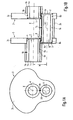
- 1A and 1B show a first embodiment of a built crankshaft for a piston lifting machine.
- 1A shows the side view of a crank web 3 in Direction of the axis of rotation X of the crankshaft.
- 1B shows a sectional view along the axis of rotation X of an end portion of the crankshaft.
- the crankshaft according to the first embodiment has a plurality of Crank bearing elements 1 (in FIG. 1B, the left crank bearing element is complete and the right crank bearing elements partially shown) for mounting the crankshaft.
- the crank bearing elements 1 of the crankshaft are in bearings in a crankcase (Not shown) of the piston lifting machine.
- the crank bearing elements 1 are cylindrical formed and extend symmetrically to the axis of rotation X of the Crankshaft.
- the crankshaft has a plurality of pin bearing elements 2 (a single pin bearing member shown in Fig. 1B) for connecting rod storage (not shown) of the piston lifting machine.
- each lifting bearing element can have a single connecting rod or two connecting rods.
- the pin bearing elements 2 are cylindrical and extend parallel to the axis of rotation X of the crankshaft.
- a central axis X1 of the thrust bearing element 2 is around the stroke (amount) of the crankshaft the axis of rotation X of the crankshaft.
- crank webs 3 (two shown in FIG. 1B) of the Crankshaft.
- the crank arm 3 connects the crank bearing element 1 to the pin bearing element 2.
- the pin bearing member 2 is with the two shown Crank cheeks 3 connected.
- each of the crank webs shown is 3 each connected to a crank bearing element 1.
- the crank webs 3 are plate-shaped. Each of the crank webs 3 has a crank bearing opening 4 and a pin bearing opening 5 on.
- the crank bearing opening 4 receives the crank bearing element 1 and is concentric with the axis of rotation X of the crankshaft.
- the pin bearing opening 5 of the crank arm 3 receives the pin bearing element 2 and is concentrically increased the central axis X1 of this pin bearing element 2 is formed.
- the crank bearing element 1 is fastened in the crank bearing opening 4 of the crank web 3.
- the pin bearing element 2 is fastened in the crank bearing opening 5 of the crank arm 3.
- each of the crank arms 3 has a compensating section 3c as shown in Figs. 1A and 1B on. This compensation section 3c is used for mass compensation of the pin bearing element 2 and the elements (connecting rods and pistons, not shown) of the piston lifting machine mounted thereon.
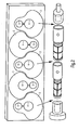
- Fig. 2 shows the individual parts of the built crankshaft for a piston lifting machine according to the first embodiment.
- the crank webs 3 are made from a plate cut out with optimized thickness. This makes it easy to do Create crank webs with regard to their mass (balance weight) and their Strength are optimized.
- the crank bearing elements 1 and pin bearing element 2 are in the Essentially made up of simple cylinder parts. These cylinder parts are in simpler Formed from tubular parts, both strength and weight the parts are optimized.
- crank bearing elements 1 and the pin bearing elements 2 allow a high moment of resistance against bending and torsion of these elements at a relatively low weight.
- the crank bearing elements 1 and the pin bearing elements 2 are in the respective openings 4 and 5 of the crank arm 3 e.g. by pressing and / or welding, in particular laser welding.
- crank webs 3 and the design of the crank bearing elements 1 and the pin bearing elements 2 is not determined by the restrictions as they are exist in a forging or casting process.
- individual parts can be used that are in can be easily machined by machines without expensive forging or casting molds must be used.
- crankshafts 3 the crank bearing elements 1 and the pin bearing elements 2 each as Identical parts can be used for different crankshafts.
- one pin bearing element, two identical crank cheeks and two crank bearing elements, which are designed as end bearings, assembled into a single-cylinder crankshaft become.
- three pin bearing elements, four crank bearing elements and six crank cheeks assembled into a three-cylinder crankshaft become.
- crankshafts can be used for different Cylinder numbers are produced, with the same parts for the different crankshafts be used.
- the built crankshaft according to the first embodiment is therefore designed as a modular system that can be assembled.
- Another advantage of this modular structure is the use of different ones Materials for the individual parts of the crankshaft as well as the possibility of different Heat treatment of the parts for the crankshaft.
- the built crankshaft is for a piston lifting machine according to the first embodiment from simple plate or cylindrical parts built.
- the built crankshaft for one Piston lifting machine is modular, the crankshaft in a simple manner producible and with high flexibility, especially with regard to the number of Connecting rods or the cylinder can be modified.
- the crank bearing element 1 according to the first embodiment of an inner cylindrical element 1a and a outer cylindrical sleeve element 1b.
- the inner element is designed as an inner cylindrical sleeve element 1a.
- the inner cylindrical sleeve member 1a and the outer cylindrical sleeve member 1b are inserted into one another such that an inner peripheral surface of the outer cylindrical sleeve member 1b on an outer peripheral surface of the inner cylindrical sleeve member 1a is mounted.
- This bushing arrangement for the crank bearing element 1 allows in a simple manner to combine different materials.
- the outer peripheral surface of the outer cylindrical sleeve element 1b with respect to the storage in the crankcase optimized.
- a hardened steel sleeve Surface for use.
- the outer peripheral surface of the outer cylindrical sleeve element a coating such as have a ceramic coating.
- the inner cylindrical sleeve member is optimized with regard to the absorption of bending and torsional loads on the crankshaft. Steels with appropriate toughness are used.
- an outer cylindrical steel sleeve an outer cylindrical one can also be used Ceramic sleeve can be used as the sleeve element 1b.
- the inner sleeve member 1a is the crank bearing member 1 inserted into the circular crank bearing opening 4 of the crank web 3.
- the outer cylindrical sleeve element 1b of the crank bearing element 1 is on the rest outer peripheral surface (which is not received in the crank bearing opening 4) of the inner sleeve member 1a mounted, with an axial end face of the outer cylindrical Sleeve element 1b in contact with a side surface of the crank arm 3 is.
- the inner cylindrical sleeve element 1a is by pressing and / or welding connected to the crank arm 3.
- the inner cylindrical sleeve member 1a into the crank bearing opening 4th used with a distance t between the end face of the inner cylindrical Sleeve element 1a and the adjacent side surface of the crank web 3 remains.
- This distance t (in the axial direction of the axis of rotation X of the crankshaft) creates one Space in which the inner cylindrical sleeve element 1a circumferentially or in sections can be welded to the crank web 3, as shown in Fig. 1B is shown, with no projection (weld) on the side surface of the crank web 3 is formed.
- Fig. 1B is shown, with no projection (weld) on the side surface of the crank web 3 is formed.
- the next crank bearing element 1 is corresponding Trained and inserted into the corresponding crank web 3, the opposite side surfaces of the crank arm 3 have no projections or the like., so that a connecting rod (not shown) between these side surfaces can be included. Due to the distance t, it is not necessary to a circumferential welding of the inner cylindrical sleeve element 1a to provide post-processing of the corresponding side surface of the crank arm 3.
- FIG. 1B shows a crank bearing element which acts as a final bearing on a End portion of the crankshaft is provided.
- the outer is cylindrical Sleeve element 1b formed at both end sections in an axially recessed shape, so that the two opposite end faces of the outer cylindrical Sleeve element 1b in contact with the opposite side surfaces of the opposite Crank cheeks 3 come and the outer peripheral surface on both End portions of the inner cylindrical sleeve member 1a in the respective Crank bearing openings 4 of the crank webs 3 are added.
- the crank bearing element 1 of the crankshaft according to the first embodiment has a lubricating oil channel device 6.
- This lubricating oil channel device 6 serves for supplying lubricating oil to the outer peripheral surface of the outer cylindrical Sleeve element 1b, which is mounted in the crankcase of the piston lifting machine is.
- This lubricating oil channel device 6 is essentially between the outer cylindrical sleeve member 1b and the inner cylindrical sleeve member 1a arranged.
- the exemplary embodiment according to FIG. 1B essentially shows a channel arrangement in the outer peripheral surface of the inner cylindrical Sleeve element 1a, as will be explained in detail below.
- the channels can also be in the inner Circumferential surface of the outer sleeve element or as sub-channels in both opposite Circumferential surfaces of the inner and outer cylindrical sleeve member 1a, 1b.
- the first embodiment shows an axial channel section 6a, which is in the axial Direction of the crank bearing element 1 extends.
- This is axial channel section 6a groove-shaped in the outer peripheral surface of the inner cylindrical sleeve element 1a trained.
- the lubricating oil channel device 6 has a central ring-shaped one Provided channel section 6b, which extends in the circumferential direction of the crank bearing element 1 extends.
- This annular channel section 6b is groove-shaped in the outer Circumferential surface of the inner cylindrical sleeve member 1a is formed and is in fluid communication with the axial channel section 6a.
- a radial Channel section 6c is provided, which extends in the radial direction of the crank bearing element 1 to the outer peripheral surface of the outer cylindrical sleeve member 1b extends.
- This radial channel section 6c is ring-shaped Channel section 6b in fluid communication.
- This lubricating oil channel device 6 is pressurized with lubricating oil a pressure oil supply (not shown) supplied with lubricating oil.
- several axial channel sections with one or more annular channel sections are connected.
- several radial channel sections in connection with one or more annular channel sections be provided.
- crank bearing element 1 there is a crank bearing element 1 on the left side shown that forms a final bearing of the crankshaft.
- the axial channel section extends 6a up to the annular channel section 6b in the central section of the crank bearing element 1.
- crank bearing element 1 With a crank bearing element 1 in a middle section of the The crankshaft extends the axial channel section 6a over the lying in the middle annular channel section 6b to the next crank arm.
- the Lubricating oil devices 6 of the crank bearing elements 1 are with lubricating oil devices the pin bearing elements 2 connected in the region of the crank webs 3, as follows will be explained later.
- the pin bearing element 2 is in accordance with the first Embodiment of an inner cylindrical element 2a and an outer cylindrical sleeve element 2b.
- this is inner element formed as an inner cylindrical sleeve member 2a.
- the inner cylindrical sleeve element 2a and the outer cylindrical sleeve element 2b are inserted into each other such that an inner peripheral surface of the outer cylindrical Sleeve member 2b on an outer peripheral surface of the inner cylindrical sleeve element 2a is mounted.
- This bushing arrangement for the pin bearing element 2 allows, similar to that Crank bearing element 1, in a simple way to different materials together combine.
- the outer peripheral surface of the outer cylindrical sleeve element 2b optimized with regard to the storage of the connecting rod.
- a steel sleeve with a hardened surface is used here.
- the outer peripheral surface of the outer cylindrical sleeve member have a coating such as a ceramic coating.
- the inner cylindrical sleeve element is with regard to the absorption of bending and torsional loads the crankshaft optimized. Steels come with the corresponding Toughness to use.
- an outer cylindrical steel sleeve an outer cylindrical one can also be used Ceramic sleeve can be used as the sleeve element 2b.
- the inner sleeve member 2a of the pin bearing member 2 is in the circular pin bearing opening 5 of the crank arm 3 is used. There is one axial end portion of the outer peripheral surface of the inner sleeve member 2a in Contact with the circular peripheral surface of the pin bearing opening 5.
- the outer cylindrical Sleeve element 2b of the pin bearing element 2 is on the remaining outer Circumferential surface (which is not received in the pin bearing opening 5) of the inner Sleeve element 2a mounted, with an axial end face of the outer cylindrical Sleeve element 2b is in contact with a side surface of the crank arm 3.
- the inner cylindrical sleeve element 2a is by pressing and / or welding connected to the crank arm 3.
- the inner cylindrical sleeve element 2a into the pin bearing opening 5 used with a distance k between the end face of the inner cylindrical Sleeve element 2a and the adjacent side surface of the crank web 3 remains.
- This distance k (in the axial direction of the axis of rotation X of the crankshaft) creates a space in which the inner cylindrical sleeve element 2a or can be welded in sections to the crank web 3, as shown in FIG. 1B is shown, with no projection (weld) on the side surface of the crank web 3 is formed.
- the next crank arm 3 is corresponding Way connected to the pin bearing element 2.
- crank webs 3 have no projections or the like due to the welding (similar to FIG Welding the crank bearing elements), so that the crankshaft in the Crankcase can be stored. Due to the distance k, it is not necessary with a circumferential welding of the inner cylindrical sleeve element 2a a reworking of the corresponding side surface of the crank web 3 provided.
- FIG. 1B shows a pin bearing element 2, which is in a central portion of the crankshaft is arranged and connects two crank webs 3 together.
- the outer cylindrical sleeve element 2b is axially recessed at both end sections Formed so that the two opposite end faces of the outer cylindrical sleeve element 2b in contact with the opposite side surfaces the opposite crank cheeks 3 come and the outer peripheral surface at both end portions of the inner cylindrical sleeve member 2a are received in the respective lifting bearing openings 5 of the crank webs 3.
- the pin bearing element 2 of the crankshaft according to the first embodiment has a lubricating oil channel device 7.
- This lubricating oil channel device 7 is used Supply of lubricating oil to the outer peripheral surface of the outer cylindrical Sleeve element 2b, which supports a connecting rod of the piston lifting machine.
- This Lubricating oil channel device 7 is essentially between the outer cylindrical Sleeve element 2b and the inner cylindrical sleeve element 2a arranged.
- the exemplary embodiment according to FIG. 1B essentially shows a channel arrangement in the outer peripheral surface of the inner cylindrical sleeve member 2a, as will be explained in detail below.
- Lube oil channel device can also the channels in the inner peripheral surface of the outer sleeve element or as sub-channels in both opposite peripheral surfaces of the inner and the outer cylindrical sleeve element 2a, 2b be trained.
- the first embodiment shows an axial channel section 7a, which is in the axial Direction of the pin bearing element 2 from one end section to an opposite one End portion of the pin bearing element 2 extends.
- This axial channel section 7a is groove-shaped in the outer peripheral surface of the inner cylindrical one Sleeve element 2a formed.
- a central annular channel section 7b is provided, which extends in the circumferential direction of the pin bearing element 2 extends.
- This annular channel section 7b is groove-shaped in the outer peripheral surface of the inner cylindrical sleeve member 2a formed and is in fluid communication with the axial channel section 7a.
- a radial channel section 7c is provided, which extends in the radial direction of the Pin bearing element 2 up to the outer peripheral surface of the outer cylindrical Sleeve element 2b extends.
- This radial channel section 7c is ring-shaped Channel section 7b in fluid communication.
- a single axial channel section 7a is a single one central annular channel section 7b, and a single radial channel section 7c shown.
- several axial channel sections with one or more annular channel sections are connected.
- several radial channel sections in connection with one or more annular channel sections be provided.
- the lubricating oil channel device 6 of the crank bearing element 1 is with the lubricating oil channel device 7 of the pin bearing element 2 connected.
- the lubricating oil supply to the Lubricating oil channel device 7 of the pin bearing element 2 takes place via this connection through the lubricating oil channel device 6 of the crank bearing element 1.
- This lubricating oil channel connection device 8 has an annular channel section 8a in the region of the axial end section of the Crank bearing element 1. As shown in Fig. 1, the annular channel section 8a in the area formed through the crank bearing opening 4 of the crank web 3 is included. In the embodiment shown, the annular channel section 8a in the outer peripheral surface of the inner cylindrical sleeve member 1a of the crank bearing element 1 is formed. Alternatively, the annular Channel portion may be formed in the peripheral surface of the crank bearing opening or there can be corresponding annular channel sections both on the crank bearing element as well as be formed in the crank bearing opening.
- this lubricating oil passage connection device 8 has an annular passage section 8b in the area of the axial end section of the pin bearing element 2.
- the annular channel portion 8b is formed in the area through the pin bearing opening 5 of the crank web 3 is received.
- the annular channel portion in the peripheral surface of the Hub bearing opening can be formed or there can be corresponding annular channel sections formed both on the pin bearing element and in the pin bearing opening his.
- the annular channel section 8a in the region of the crank bearing element 1 is connected to the annular channel section 8b connected in the area of the pin bearing element 2.
- a radial channel section 8c is provided in the crank web, which extends from the Crank bearing opening extends to the pin bearing opening as shown in Figs. 1A and 1B is shown.
- the first embodiment of the crankshaft is designed such that the stroke H the crankshaft is greater than the sum of the radius of the crank bearing element 1 and the radius of the pin bearing element 2.
- the stroke H is greater than the sum of the radius of the outer Circumferential surface of the inner sleeve element 1 a of the crank bearing element 1 and the radius of the outer peripheral surface of the inner sleeve member 2a of the Stub bearing element 2.
- the radial channel section 8c Lubricating oil connection channel device 8 are formed in the crank web 3.
- Such a crankshaft is also referred to as a long-stroke crankshaft.
- the stroke of the crankshaft can be shortened by for example the radii of the parts of the crank bearing elements and the pin bearing elements is reduced.
- both the crank bearing elements are 1 as well as the pin bearing elements 2 as parts of hydrodynamic Plain bearings provided.
- the hydrodynamic plain bearings instead of the hydrodynamic plain bearings also used roller bearings in a simple manner be by using appropriate bearings before final assembly of the crankshaft, in particular final assembly with one-piece connecting rods via bearing elements 1 and 2 be put.
- the outer cylindrical sleeve elements 1b and 2b of the crank bearing elements 1 and the pin bearing elements 2 as inner ones Races of corresponding roller bearings are formed.
- the rolling bearings can especially rollers or needle bearings are used.
- An advantage of storage with rolling bearings is, for example, the good emergency running property in the event of pressure oil loss.
- crank webs 3 are essentially as plate-shaped elements with a uniform thickness with respect to the axial direction of the crankshaft educated.
- each crank arm is as one-piece element formed.
- each crank web is 3 by a first plate-shaped crank cheek element 3a and a second plate-shaped one Crank element 3b formed, as shown in Fig. 3.
- the first and the second plate-shaped crank cheek element 3a, 3b lie axially End faces together and are connected to the crank web 3.
- the plate-shaped Crank cheek elements 3a, 3b thus extend essentially parallel to each other.
- this first and second plate-shaped crank cheek element 3a, 3b substantially the same Outer contour on and are formed with the same thickness.
- the first crank arm element 3a has the pin bearing opening 5 around the pin bearing element 2 record.
- the second crank arm element 3b has the crank bearing opening 4 to accommodate the crank bearing element 1.
- the design of the Crank bearing element 1 and the pin bearing element 2, in particular the receptacle in the crank or lifting bearing openings 4 and 5 and the formation of the lubricating oil channel devices 6 and 7 of the second embodiment is essentially identical with that of the first embodiment described in connection with FIGS. 1 and 2 is. The following are essentially the differences of the second Embodiment explained to the first embodiment.
- the lubricating oil channel device is in the second exemplary embodiment 6 of the crank bearing element 1 and the lubricating oil channel device 7 of the pin bearing element 2 formed the same as those of the first embodiment.
- the second embodiment is the lubricating oil connection channel device 8, which the lubricating oil channel device 6 of the crank bearing element 1 and the lubricating oil channel device 7 of the pin bearing element 2 connects, formed by recesses 8d, those in the opposite side surfaces of the first and second plate-shaped ones Crank cheek element 3a, 3b are formed.
- Another circular recess is in the side surface of the second plate-shaped crank cheek element 3b, which with an annular channel section 8a is connected, which in the pin bearing opening 4th is trained. These two circular recesses are overlapping, as shown in Fig. 3, so that the circular channel sections 8a and 8b are in fluid communication with each other. As in connection with the first Explained embodiment, the annular channel sections 8a and 8b are each in connection with the lubricating oil channel device 6 of the crank bearing element 1 and the lubricating oil channel device 7 of the pin bearing element 2.
- the first and second crank arm elements 3a, 3b are made in a corresponding manner a plate, as shown in Fig. 4, cut out. This allows the first and second crank arm elements can be produced in a simple manner.
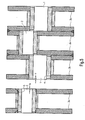
- crank bearing element 1 in the crank bearing opening 4 of the second crank arm element 3b is carried out in a corresponding manner as for the first exemplary embodiment explained and shown in Fig. 5.
- the insertion of the pin bearing element 2 in the pin bearing opening 5 of the first crank arm element 3a also takes place in a corresponding manner, as in connection with the first embodiment and shown in Fig. 5.
- the distances t and k become the side surfaces of the crank cheek elements are formed, which abut each other, such as this is shown in Fig. 5.
- first crank member 3a and the second crankshaft element 3b welded together along the outer circumferential contour.
- first crank arm element 3a and the second crank arm element 3b is also soldered, glued or screwed be, a combination of the methods mentioned are used can.
- the lifting bearing opening is 5 formed in the first crank arm element 3a; and the crank bearing opening 4 is formed in the second crank arm element 3b.
- the stroke H of the crankshaft is determined by the distance between the crankshaft axis X (central axis of the crank bearing opening 4) from the central axis X1 of the pin bearing element 2 (the pin bearing opening 5) determined. Due to the separate design of the pin bearing opening 5 and the crank bearing opening 4, these openings can overlap (as shown in Fig. 3).
- a pin bearing element forms 2 and at least one first plate-shaped crank arm element 3a Pin bearing mounting unit in which the pin bearing element 2 in the pin bearing opening 5 is attached.
- a crank bearing element 1 and a second plate-shaped crank cheek element 3b form a crank bearing assembly unit in which the crank bearing element 1 in the crank bearing opening 4 of the second plate-shaped crank cheek element 3b is attached.
- This pin bearing mounting unit and this crank bearing mounting unit are assembled by the first plate-shaped crank cheek element 3a connected to the second plate-shaped crank cheek element 3b, is welded to one another in particular in the circumferential direction, as is shown in FIG. 5 evident.
- the pin bearing assembly unit comprises the pin bearing element 2 and two first plate-shaped crank cheek elements 3a and the crank bearing assembly unit, the crank bearing element 1, the two second plate-shaped crank cheek elements 3b is connected.
- the first and the second plate-shaped crank cheek element 3a, 3b are welded joined together on their outer contour.
- a one-piece connecting rod (not shown) are attached to the pin bearing element 2 before the two plate-shaped Crank beam elements 3a can be mounted.
- the pin bearing assembly unit for Different crankshafts prefabricated as identical parts regardless of the number of cylinders become.
- the special design of the pin bearing assembly unit only defines the stroke the crankshaft.
- crank bearing assembly unit can be used for different crankshafts Hubs are provided as the same part. Due to the arrangement (twisting to each other around the crankshaft axis X) of the two second crank web elements 3b Crank bearing assembly unit is the crank offset (crank offset) of the pin bearing elements 2 set. This determination is made depending on the number of cylinders in the piston lifting machine.
- piston lifting machines with different numbers of cylinders can have the same lifting element offset, so that the crank bearing assembly unit as the same part for crankshafts with different strokes and in conditional Different numbers of cylinders can be provided.
- crankshaft and the modular assembly over the described Pivot bearing assembly units and crank bearing assembly units enabled it to manufacture a variety of different crankshafts, the high Share of manufacturing costs, storage and logistics costs are significantly reduced can be. Furthermore, the modular design allows the crankshaft to be shortened Time and easily adapted to a modified piston lifting machine become.
- the pin bearing element 2 is first inserted into the pin bearing opening 5 the crank arm 3 inserted and fastened to form a pin bearing assembly. Furthermore, the crank bearing element 1 is in the crank bearing opening 4 of another Crank cheek 3 inserted and attached to a crank bearing assembly form.
- a pin bearing assembly unit will alternate with one Crank bearing assembly assembled.
- the pin bearing element 2 is the Pin bearing mounting unit in a pin bearing opening 5 of the crank arm 3 of the crank bearing mounting unit used and attached.
- the crank bearing element the crank bearing assembly unit in the crank bearing opening 4 of the crank arm 3 Pin bearing mounting unit inserted and fastened.
- a one-piece connecting rod (not shown) can be on the pin bearing element 2 be put on.
- crank offset (crank offset) of the pin bearing elements 2 is corresponding to the predetermined number of cylinders when inserting and positioning the crank bearing element 1 of the crank bearing mounting unit in the crank bearing opening 4 of the crank web 3 the subsequent pin bearing assembly unit.
- FIG Assembly sequence As follows: 1-2-3-connecting rods-4-5-6-7-connecting rods-8-9-10-11-connecting rods-12.
- crankshaft for a piston lifting machine, in particular an internal combustion engine, with at least one crank bearing element 1 for Storage of the crankshaft, and at least one pin bearing element 2 for storage a connecting rod and at least one crank web 3, which the crank bearing element 1 connects to the pin bearing element 2.
- the crankshaft is modular and the crank bearing element 1 is in a crank bearing opening 4 of the crank web 3 attached and the pin bearing element 2 is in a pin bearing opening 5 of the crank arm 3 is attached.
- the crank bearing element 1 has an inner cylindrical element 1a and an outer one cylindrical sleeve element 1b. An inner peripheral surface of the outer cylindrical sleeve member 1b is on an outer peripheral surface of the inner one cylindrical element 1 a stored.
- the inner cylindrical element 1 a of Crank bearing element 1 is designed as an inner cylindrical sleeve element.
- the outer cylindrical sleeve element 1b of the crank bearing element 1 has a coating, in particular made of ceramic.
- the outer cylindrical sleeve element 1b of the crank bearing element 1 made of ceramic.
- the exemplary embodiments describe a crankshaft in which the outer cylindrical Sleeve element 1b of the crank bearing element 1 and / or the inner cylindrical Element 1a of the crank bearing element 1 has a lubricating oil channel device 6.
- the lubricating oil channel device 6 of the crank bearing element 1 has at least one axial one Channel section 6a, which extends in the axial direction of the crank bearing element 1.
- the axial channel section 6a is groove-shaped in the inner peripheral surface of the outer one cylindrical sleeve element of the crank bearing element 1 and / or in the outer peripheral surface of the inner cylindrical member 1a of the crank bearing member 1 trained.
- the lubricating oil channel device 6 also has at least one annular channel portion 6b, which extends in the circumferential direction of the crank bearing element 1 extends.
- the annular channel portion 6b is groove-shaped in the inner peripheral surface of the outer cylindrical sleeve element 1b of the crank bearing element 1 and / or in the outer peripheral surface of the inner cylindrical element 1a of the Crank bearing element 1 is formed.
- the lubricating oil channel device 6 of the crank bearing element 1 furthermore has at least one radial channel section 6c, which is in radial direction of the crank bearing element 1 to an outer peripheral surface of the outer cylindrical sleeve member 1b extends.
- the pin bearing element 2 has an inner cylindrical element 2a and an outer one cylindrical sleeve element 2b.
- An inner peripheral surface of the outer cylindrical Sleeve member 2b is on an outer peripheral surface of the inner cylindrical one Element 2a stored.
- the inner cylindrical element of the pin bearing element 2 is designed as an inner cylindrical sleeve element 2a.
- the outer cylindrical sleeve element 2b of the pin bearing element 2 has a coating, in particular made of ceramic.
- outer cylindrical sleeve element 2b of the Pin bearing element 2 formed from ceramic.
- the embodiment describe a crankshaft in which the outer cylindrical Sleeve element 2b of the pin bearing element 2 and / or the inner cylindrical Element 2a of the pin bearing element 2 has a lubricating oil channel device 7.
- This Lubricating oil channel device 7 of the pin bearing element 2 has at least one axial one Channel section 7a, which extends in the axial direction of the pin bearing element 2.
- the axial channel portion 7a is groove-shaped in the inner peripheral surface of the outer one cylindrical sleeve element 2b of the pin bearing element 2 and / or in the outer Circumferential surface of the inner cylindrical element 2a of the pin bearing element 2 is formed.
- the lubricating oil channel device 7 also has at least one ring-shaped one Channel section 7b, which extends in the circumferential direction of the pin bearing element 2.
- the annular channel portion 7b is groove-shaped in the inner peripheral surface of the outer one cylindrical sleeve element 2b of the pin bearing element 2 and / or in the outer Circumferential surface of the inner cylindrical element 2a of the pin bearing element 2 educated.
- the lubricating oil channel device 7 of the pin bearing element 2 also has at least one radial channel section 7c, which extends in the radial direction of the pin bearing element 2 to an outer peripheral surface of the outer cylindrical sleeve member 2b extends.
- an outer peripheral surface section is one End portion of the crank bearing element 1 in the crank bearing opening 4 of the crank arm 3 added.
- An outer peripheral surface portion of an end portion of the Pin bearing element 2 is received in pin bearing opening 5 of crank arm 3.
- the lubricating oil connection channel device 8 connects the lubricating oil channel device 6 of the crank bearing element 1 with a lubricating oil channel device 7 of the pin bearing element 2.
- the lubricating oil connection channel device has an annular channel section 8a in the crank arm 3 in the area of the crank bearing opening 4 and / or in the area of the end portion of the crank bearing element 1.
- annular Channel section 8b in the crank web 3 in the region of the lifting bearing opening 5 and / or in Area of the end portion of the pin bearing element 2 is provided.
- This ring-shaped Channel sections 8a, 8b are connected to one another.
- the annular channel section 8a in the crank arm 3 in the area of the crank bearing opening 4 and / or in the area of the End portion of the crank bearing element 1 is groove-shaped in an inner peripheral surface the crank bearing opening 4 and / or an outer peripheral surface of the end portion of the crank bearing element 1 is formed.
- the annular channel section 8b in the crank web 3 in the area of the pin bearing opening 5 and / or in the area of the end section of the pin bearing element 2 is groove-shaped in an inner peripheral surface of the pin bearing opening 5 and / or an outer peripheral surface of the end portion of the pin bearing element 2 trained.
- crankshaft has crank webs 3, which are essentially plate-shaped, in particular with a uniform thickness in the axial direction of the Crankshaft are formed.
- the crank arm has 3 shows a first and a second plate-shaped crank web element 3a, 3b, which extend essentially parallel to each other and with opposite Side surfaces are in contact with each other.
- the first crank arm element 3a has the Lifting bearing opening 5 and the second crank arm element 3b has the crank bearing opening 4 on.
- the first and the second crank arm elements 3a, 3b each have same circumferential contour areas.
- the first and second cheek piece are connected to each other in the area of the peripheral contour surfaces, in particular welded.
- the lubricating oil connection channel device 8 has recesses in the opposite Side surfaces of the first and / or second plate-shaped crank cheek element 3a, 3b.
- connection of the crank bearing elements or the pin bearing elements with the crank webs by pressing and / or Welding reached.
- the elements mentioned can also be used Soldering, gluing, screwing or shrinking together.
- the crank bearing elements and the pin bearing elements must match the crank arms be frictionally connected, so that the angular position between them Elements not changed.
- an additional positive connection can be provided in the form of a toothing. there the angular position for the assembly is determined in a simple manner.
- the built crankshaft according to the exemplary embodiments shown can be highly automated Way. Due to the high number of identical parts as well the use of similar parts can reduce the design effort and the Reduce manufacturing costs significantly, especially with regard to the different Design of the respective crankshaft.
- the modular structure enables materials with regard to the different Select functions of the parts of the crankshaft and thus a further weight reduction to reach. Since the crankshaft is a moving (rotating) Mass in the piston lifting machine, for example an engine of a motor vehicle acts, this weight reduction is synonymous with a more agile Behavior with regard to speed changes and a reduction in energy consumption.
- Another major advantage is the use of closed or one-piece Connecting rods. These can be made smaller by eliminating split bearings and therefore easier to execute. The resulting weight saving works on the counterweights of the crank webs, so that in turn another Reduction of the rotary masses can take place.
Landscapes
- Engineering & Computer Science (AREA)
- General Engineering & Computer Science (AREA)
- Ocean & Marine Engineering (AREA)
- Mechanical Engineering (AREA)
- Shafts, Cranks, Connecting Bars, And Related Bearings (AREA)
Abstract
Description
- Fig. 1A und 1B
- ein erstes Ausführungsbeispiel einer gebauten Kurbelwelle für eine Kolbenhubmaschine,
- Fig. 2
- die einzelnen Teile der gebauten Kurbelwelle für eine Kolbenhubmaschine gemäß dem erste Ausführungsbeispiel,
- Fig. 3
- eine Kurbelwange der gebauten Kurbelwelle gemäß eines zweiten Ausführungsbeispiels,
- Fig. 4
- Teile der Kurbelwange der gebauten Kurbelwelle gemäß des zweiten Ausführungsbeispiels,
- Fig. 5
- eine gebauten Kurbelwelle gemäß des zweiten Ausführungsbeispiels,
- Fig. 6
- eine Montagefolge der gebauten Kurbelwelle.
Claims (38)
- Kurbelwelle für eine Kolbenhubmaschine, insbesondere eine Brennkraftmaschine, mit zumindest einem Kurbellagerelement (1) zur Lagerung der Kurbelwelle, zumindest einem Hublagerelement (2) zur Lagerung einer Pleuelstange und zumindest einer Kurbelwange (3), welche das Kurbellagerelement (1) mit dem Hublagerelement (2) verbindet, dadurch gekennzeichnet, daß die Kurbelwelle modular aufgebaut ist und das Kurbellagerelement (1) in einer Kurbellageröffnung (4) der Kurbelwange (3) befestigt ist und das Hublagerelement (2) in einer Hublageröffnung (5) der Kurbelwange (3) befestigt ist.
- Kurbelwelle nach Anspruch 1, dadurch gekennzeichnet, daß das Kurbellagerelement (1) ein inneres zylinderförmiges Element (1a) und ein äußeres zylinderförmiges Hülsenelement (1b) aufweist, wobei eine innere Umfangsfläche des äußeren zylinderförmigen Hülsenelementes (1b) auf einer äußeren Umfangsfläche des inneren zylinderförmigen Elementes (1a) gelagert ist.
- Kurbelwelle nach Anspruch 2, dadurch gekennzeichnet, daß das innere zylinderförmige Element (1a) des Kurbellagerelementes (1) als inneres zylinderförmiges Hülsenelement ausgebildet ist.
- Kurbelwelle nach Anspruch 2 oder 3, dadurch gekennzeichnet, daß das äußere zylinderförmige Hülsenelement (1b) des Kurbellagerelementes (1) eine Beschichtung, insbesondere aus Keramik, aufweist.
- Kurbelwelle nach Anspruch 2 oder 3, dadurch gekennzeichnet, daß das äußere zylinderförmige Hülsenelement (1b) des Kurbellagerelementes (1) aus Keramik gebildet ist.
- Kurbelwelle nach einem der Ansprüche 2 bis 5, dadurch gekennzeichnet, daß das äußere zylinderförmige Hülsenelement (1b) des Kurbellagerelementes (1) und/oder das innere zylinderförmige Element (1a) des Kurbellagerelementes (1) eine Schmierölkanaleinrichtung (6) aufweist.
- Kurbelwelle nach Anspruch 6, dadurch gekennzeichnet, daß die Schmierölkanaleinrichtung (6) des Kurbellagerelementes (1) zumindest einen axialen Kanalabschnitt (6a) aufweist, der sich in axialer Richtung des Kurbellagerelementes (1) erstreckt.
- Kurbelwelle nach Anspruch 7, dadurch gekennzeichnet, daß der axiale Kanalabschnitt (6a) nutförmig in der inneren Umfangsfläche des äußeren zylinderförmigen Hülsenelement des Kurbellagerelementes (1) und/oder in der äußeren Umfangsfläche des inneren zylinderförmigen Element (1a) des Kurbellagerelementes (1) ausgebildet ist.
- Kurbelwelle nach zumindest einem der Ansprüche 6 bis 8, dadurch gekennzeichnet, daß die Schmierölkanaleinrichtung (6) zumindest einen ringförmigen Kanalabschnitt (6b) aufweist, der sich in Umfangsrichtung des Kurbellagerelementes (1) erstreckt.
- Kurbelwelle nach Anspruch 9, dadurch gekennzeichnet, daß der ringförmige Kanalabschnitt (6b) nutförmig in der inneren Umfangsfläche des äußeren zylinderförmigen Hülsenelement (1b) des Kurbellagerelementes (1) und/oder in der äußeren Umfangsfläche des inneren zylinderförmigen Element (1a) des Kurbellagerelementes (1) ausgebildet ist.
- Kurbelwelle nach zumindest einem der Ansprüche 6 bis 10, dadurch gekennzeichnet, daß die Schmierölkanaleinrichtung (6) des Kurbellagerelementes (1) zumindest einen radialen Kanalabschnitt (6c) aufweist, der sich in radialer Richtung des Kurbellagerelementes (1) bis zu einer äußeren Umfangsfläche des äußeren zylinderförmigen Hülsenelementes (1b) erstreckt.
- Kurbelwelle nach zumindest einem der Ansprüche 1 bis 11, dadurch gekennzeichnet, daß das Hublagerelement (2) ein inneres zylinderförmiges Element (2a) und ein äußeres zylinderförmiges Hülsenelement (2b) aufweist, wobei eine innere Umfangsfläche des äußeren zylinderförmigen Hülsenelementes (2b) auf einer äußeren Umfangsfläche des inneren zylinderförmigen Elementes (2a) gelagert ist.
- Kurbelwelle nach Anspruch 12, dadurch gekennzeichnet, daß das innere zylinderförmige Element des Hublagerelementes (2) als inneres zylinderförmiges Hülsenelement (2a) ausgebildet ist.
- Kurbelwelle nach Anspruch 12 oder 13, dadurch gekennzeichnet, daß das äußere zylinderförmige Hülsenelement (2b) des Hublagerelementes (2) eine Beschichtung, insbesondere aus Keramik, aufweist.
- Kurbelwelle nach Anspruch 12 oder 13, dadurch gekennzeichnet, daß das äußere zylinderförmige Hülsenelement (2b) des Hublagerelementes (2) aus Keramik gebildet ist.
- Kurbelwelle nach einem der Ansprüche 12 bis 15, dadurch gekennzeichnet, daß das äußere zylinderförmige Hülsenelement (2b) des Hublagerelementes (2) und/oder das innere zylinderförmige Element (2a) des Hublagerelementes (2) eine Schmierölkanaleinrichtung (7) aufweist.
- Kurbelwelle nach Anspruch 16, dadurch gekennzeichnet, daß die Schmierölkanaleinrichtung (7) des Hublagerelementes (2) zumindest einen axialen Kanalabschnitt (7a) aufweist, der sich in axialer Richtung des Hublagerelementes (2) erstreckt.
- Kurbelwelle nach Anspruch 17, dadurch gekennzeichnet, daß der axiale Kanalabschnitt (7a) nutförmig in der inneren Umfangsfläche des äußeren zylinderförmigen Hülsenelement (2b) des Hublagerelementes (2) und/oder in der äußeren Umfangsfläche des inneren zylinderförmigen Element (2a) des Hublagerelementes (2) ausgebildet ist.
- Kurbelwelle nach zumindest einem der Ansprüche 16 bis 18, dadurch gekennzeichnet, daß die Schmierölkanaleinrichtung (7) zumindest einen ringförmigen Kanalabschnitt (7b) aufweist, der sich in Umfangsrichtung des Hublagerelementes (2) erstreckt.
- Kurbelwelle nach Anspruch 19, dadurch gekennzeichnet, daß der ringförmige Kanalabschnitt (7b) nutförmig in der inneren Umfangsfläche des äußeren zylinderförmigen Hülsenelement (2b) des Hublagerelementes (2) und/oder in der äußeren Umfangsfläche des inneren zylinderförmigen Element (2a) des Hublagerelementes (2) ausgebildet ist.
- Kurbelwelle nach zumindest einem der Ansprüche 16 bis 20, dadurch gekennzeichnet, daß die Schmierölkanaleinrichtung (7) des Hublagerelementes (2) zumindest einen radialen Kanalabschnitt (7c) aufweist, der sich in radialer Richtung des Hublagerelementes (2) bis zu einer äußeren Umfangsfläche des äußeren zylinderförmigen Hülsenelementes (2b) erstreckt.
- Kurbelwelle nach zumindest einem der Ansprüche 1 bis 21, dadurch gekennzeichnet, daß ein äußerer Umfangsflächenabschnitt eines Endabschnittes des Kurbellagerelementes (1) in der Kurbellageröffnung (4) der Kurbelwange (3) aufgenommen ist, ein äußerer Umfangsflächenabschnitt eines Endabschnittes des Hublagerelementes (2) in der Hublageröffnung (5) der Kurbelwange (3) aufgenommen ist, wobei eine Schmierölverbindungskanaleinrichtung (8) vorgesehen ist, die eine Schmierölkanaleinrichtung (6) des Kurbellagerelementes (1) mit einer Schmierölkanaleinrichtung (7) des Hublagerelementes (2) verbindet.
- Kurbelwelle nach Anspruch 22, dadurch gekennzeichnet, daß die Schmierölverbindungskanaleinrichtung einen ringförmigen Kanalabschnitt (8a) in der Kurbelwange (3) im Bereich der Kurbellageröffnung (4) und/oder im Bereich des Endabschnittes des Kurbellagerelementes (1) aufweist, und einen ringförmigen Kanalabschnitt (8b) in der Kurbelwange (3) im Bereich der Hublageröffnung (5) und/oder im Bereich des Endabschnittes des Hublagerelementes (2) aufweist, wobei die ringförmigen Kanalabschnitte (8a,8b) miteinander verbunden sind.
- Kurbelwelle nach Anspruch 23, dadurch gekennzeichnet, daß der ringförmigen Kanalabschnitt (8a) in der Kurbelwange (3) im Bereich der Kurbellageröffnung (4) und/oder im Bereich des Endabschnittes des Kurbellagerelementes (1) nutförmig in einer inneren Umfangsfläche der Kurbellageröffnung (4) und/oder einer äußeren Umfangsfläche des Endabschnittes des Kurbellagerelementes (1) ausgebildet ist.
- Kurbelwelle nach Anspruch 23 oder 24, dadurch gekennzeichnet, daß der ringförmigen Kanalabschnitt (8b) in der Kurbelwange (3) im Bereich der Hublageröffnung (5) und/oder im Bereich des Endabschnittes des Hublagerelementes (2) nutförmig in einer inneren Umfangsfläche der Hublageröffnung (5) und/oder einer äußeren Umfangsfläche des Endabschnittes des Hublagerelementes (2) ausgebildet ist.
- Kurbelwelle nach zumindest einem der Ansprüche 1 bis 25, dadurch gekennzeichnet, daß die Kurbelwange (3) im wesentlichen plattenförmig, insbesondere mit gleichmäßiger Dicke in axialer Richtung der Kurbelwelle ausgebildet ist.
- Kurbelwelle nach Anspruch 26, dadurch gekennzeichnet, daß die Kurbelwange (3) ein erstes und ein zweites plattenförmiges Kurbelwangenelement (3a,3b) aufweist, die sich im wesentlichen parallel zueinander erstrecken und mit gegenüberliegenden Seitenflächen in Anlage zueinander sind.
- Kurbelwelle nach Anspruch 27, dadurch gekennzeichnet, daß das erste Kurbelwangenelement (3a) die Hublageröffnung (5) aufweist und das zweite Kurbelwangenelement (3b) die Kurbellageröffnung (4) aufweist.
- Kurbelwelle nach Anspruch 27 oder 28, dadurch gekennzeichnet, daß das erste und das zweite Kurbelwangenelement (3a,3b) jeweils gleiche Umfangskonturenflächen aufweisen.
- Kurbelwelle nach Anspruch 29, dadurch gekennzeichnet, daß das erste und das zweite Kurbelwangenelement jeweils im Bereich der Umfangskonturenflächen miteinander verbunden, insbesondere verschweißt, sind.
- Kurbelwelle nach zumindest einem der Ansprüche 27 bis 30, dadurch gekennzeichnet, daß eine Schmierölverbindungskanaleinrichtung (8) in dem ersten und/oder zweiten plattenförmigen Kurbelwangenelement (3a,3b) vorgesehen ist, die eine Schmierölkanaleinrichtung (6) des Kurbellagerelementes (1) mit einer Schmierölkanaleinrichtung (7) des Hublagerelementes (2) verbindet, wobei die Schmierölverbindungskanaleinrichtung (8) Ausnehmungen in den gegenüberliegenden Seitenflächen des ersten und/oder zweiten plattenförmigen Kurbelwangenelement (3a,3b) aufweist.
- Verfahren zur Montage einer Kurbelwelle, die modular aufgebaut ist und ein Kurbellagerelement (1) in einer Kurbellageröffnung (4) einer Kurbelwange (3) befestigt ist und ein Hublagerelement (2) in einer Hublageröffnung (5) der Kurbelwange (3) befestigt ist, insbesondere zur Montage einer Kurbelwelle nach zumindest einem der Ansprüche 1 bis 31, wobei ein Hublagerelement (2) in einer Hublageröffnung (5) einer Kurbelwange (3) befestigt wird und eine Hublagermontageeinheit bildet, ein Kurbellagerelement (1) in einer Kurbellageröffnung (4) einer weiteren Kurbelwange (3) befestigt wird und eine Kurbellagermontageeinheit bildet, wobei nacheinander abwechselnd eine Hublagermontageeinheit mit einer Kurbellagermontageeinheit zusammengefügt wird.
- Verfahren zur Montage einer Kurbelwelle nach Anspruch 32, dadurch gekennzeichnet, daß bei der Montage einer Kurbellagermontageeinheit auf eine Hüblagermontageeinheit das Hublagerelement (2) der Hublagermontageeinheit in einer Hublageröffnung (5) der Kurbelwange (3) der Kurbellagermontageeinheit befestigt wird, und bei der Montage einer Hublagermontageeinheit auf eine Kurbellagermontageeinheit das Kurbellagerelement (1) der Kurbellagermontageeinheit in einer Kurbellageröffnung (4) der Kurbelwange (3) der Hublagermontageeinheit befestigt wird.
- Verfahren zur Montage einer Kurbelwelle nach Anspruch 32 oder 33, dadurch gekennzeichnet, daß ein einteiliges Pleuel auf das Hublagerelement (2) aufgesetzt wird.
- Verfahren zur Montage einer Kurbelwelle, die modular aufgebaut ist und ein Kurbellagerelement (1) in einer Kurbellageröffnung (4) einer Kurbelwange (3) befestigt ist und ein Hublagerelement (2) in einer Hublageröffnung (5) der Kurbelwange (3) befestigt ist, wobei die Kurbelwange (3) ein erstes und ein zweites plattenförmiges Kurbelwangenelement (3a,3b) aufweist, die sich im wesentlichen parallel zueinander erstrecken und mit gegenüberliegenden Seitenflächen in Anlage zueinander sind, insbesondere zur Montage einer Kurbelwelle nach zumindest einem der Ansprüche 27 bis 31, wobei eine Hublagermontageeinheit das Hublagerelement (2) aufweist, das in einer Hublageröffnung (5) des ersten plattenförmigen Kurbelwangenelementes (3a) befestigt ist und eine Kurbellagermontageeinheit das Kurbellagerelement (1) aufweist, das in einer Kurbellageröffnung (4) des zweiten plattenförmigen Kurbelwangenelementes (3b) befestigt ist, wobei das erste plattenförmige Kurbelwangenelemente (3a) der Hublagermontageeinheit mit dem zweiten plattenförmigen Kurbelwangenelement (3b) der Kurbellagermontageeinheit zusammengefügt wird.
- Verfahren zur Montage einer Kurbelwelle nach Anspruch 35, dadurch gekennzeichnet, daß die Hublagermontageeinheit zwei erste plattenförmige Kurbelwangenelemente (3a) aufweist, die an Endabschnitten des Hublagerelementes (2) befestigt sind und/oder die Kurbellagermontageeinheit zwei zweite plattenförmige Kurbelwangenelemente (3b) aufweist, die an Endabschnitten des Kurbellagerelementes (1) befestigt sind.
- Verfahren zur Montage einer Kurbelwelle nach Anspruch 35 oder 36, dadurch gekennzeichnet, daß das erstes und das zweite plattenförmige Kurbelwangenelement (3a,3b) durch verschweißen an deren Außenkontur zusammengefügt werden.
- Verfahren zur Montage einer Kurbelwelle nach zumindest einem der Ansprüche 35 bis 38, dadurch gekennzeichnet, daß die Hublagermontageeinheit ein einteiliges Pleuel aufweist.
Applications Claiming Priority (2)
| Application Number | Priority Date | Filing Date | Title |
|---|---|---|---|
| DE10258759 | 2002-12-16 | ||
| DE2002158759 DE10258759A1 (de) | 2002-12-16 | 2002-12-16 | Kurbelwelle für eine Kolbenhubmaschine |
Publications (3)
| Publication Number | Publication Date |
|---|---|
| EP1431594A2 true EP1431594A2 (de) | 2004-06-23 |
| EP1431594A3 EP1431594A3 (de) | 2005-07-20 |
| EP1431594B1 EP1431594B1 (de) | 2007-08-22 |
Family
ID=32336378
Family Applications (1)
| Application Number | Title | Priority Date | Filing Date |
|---|---|---|---|
| EP03023914A Expired - Lifetime EP1431594B1 (de) | 2002-12-16 | 2003-10-21 | Kurbelwelle für eine Kolbenhubmaschine |
Country Status (2)
| Country | Link |
|---|---|
| EP (1) | EP1431594B1 (de) |
| DE (2) | DE10258759A1 (de) |
Cited By (1)
| Publication number | Priority date | Publication date | Assignee | Title |
|---|---|---|---|---|
| DE102008029272A1 (de) | 2008-06-19 | 2009-12-24 | Fraunhofer-Gesellschaft zur Förderung der angewandten Forschung e.V. | Kurbelwelle für Kolbenhubmaschinen, insbesondere Brennkraftmaschinen |
Families Citing this family (1)
| Publication number | Priority date | Publication date | Assignee | Title |
|---|---|---|---|---|
| DE102005056183A1 (de) * | 2005-11-23 | 2007-05-31 | Iav Gmbh Ingenieurgesellschaft Auto Und Verkehr | Zusammengesetzte Kurbelwelle |
Family Cites Families (8)
| Publication number | Priority date | Publication date | Assignee | Title |
|---|---|---|---|---|
| GB300853A (en) * | 1928-03-09 | 1928-11-22 | Warren Noble | Improvements in or relating to crankshafts |
| GB743966A (en) * | 1953-12-11 | 1956-01-25 | Gutehoffnungshuette Sterkrade | Improvements in and relating to built-up crank-shafts |
| JPS59212138A (ja) * | 1983-05-17 | 1984-12-01 | Mazda Motor Corp | 組立式中空クランクシヤフトの製造法 |
| WO1989002037A1 (fr) * | 1987-08-22 | 1989-03-09 | Michael Schenk | Vilebrequin compose et son procede de fabrication |
| DE3737599A1 (de) * | 1987-11-05 | 1989-05-24 | Emitec Emissionstechnologie | Kurbelwelle mit verbesserter schmierung des lagerzapfens |
| DE3737600A1 (de) * | 1987-11-05 | 1989-05-18 | Emitec Emissionstechnologie | Verfahren zur herstellung von aufgebauten kurbelwellen durch aufweiten von in geteilten zapfen angeordneten huelsen |
| MX172715B (es) * | 1987-11-05 | 1994-01-10 | Emitec Emissionstechnologie | Cigueñales y procedimiento para su fabricacion |
| EP0530890B1 (de) * | 1991-09-03 | 1995-06-14 | General Motors Corporation | Gebaute Welle und Verfahren zu ihrer Herstellung |
-
2002
- 2002-12-16 DE DE2002158759 patent/DE10258759A1/de not_active Withdrawn
-
2003
- 2003-10-21 EP EP03023914A patent/EP1431594B1/de not_active Expired - Lifetime
- 2003-10-21 DE DE50308001T patent/DE50308001D1/de not_active Expired - Lifetime
Cited By (1)
| Publication number | Priority date | Publication date | Assignee | Title |
|---|---|---|---|---|
| DE102008029272A1 (de) | 2008-06-19 | 2009-12-24 | Fraunhofer-Gesellschaft zur Förderung der angewandten Forschung e.V. | Kurbelwelle für Kolbenhubmaschinen, insbesondere Brennkraftmaschinen |
Also Published As
| Publication number | Publication date |
|---|---|
| DE10258759A1 (de) | 2004-06-24 |
| DE50308001D1 (de) | 2007-10-04 |
| EP1431594B1 (de) | 2007-08-22 |
| EP1431594A3 (de) | 2005-07-20 |
Similar Documents
| Publication | Publication Date | Title |
|---|---|---|
| EP0328009B1 (de) | Gebaute Welle, insbesondere Nockenwelle, Kurbelwelle oder Getriebewelle | |
| DE19606732C2 (de) | Gefügte Mehrlagenwellen | |
| EP0494285B1 (de) | Verbindung eines auf fertigmass gefertigten zylinderkörpers | |
| EP1844216B1 (de) | Verstellbare nockenwelle, insbesondere für verbrennungsmotoren von kraftfahrzeugen, mit einer hydraulischen stelleinrichtung | |
| DE202005021715U1 (de) | Nockenwelle mit gegeneinander verdrehbaren Nocken für insbesondere Kraftfahrzeuge | |
| DE19843632B4 (de) | Gleichlaufgelenk | |
| DE102008018545A1 (de) | Welle mit Wälzlager | |
| EP0315137B1 (de) | Verfahren zur Herstellung von Kurbelwellen | |
| DE102015007470A1 (de) | Verfahren zum Herstellen einer Welle-Nabe-Verbindung | |
| DE102011012941A1 (de) | Nockenwelle mit Gewichtsverringerungsmerkmalen und Herstellungsverfahren | |
| DE69202942T2 (de) | Gebaute Welle und Verfahren zu ihrer Herstellung. | |
| EP1320689B1 (de) | Geschweisstes bundlager, verfahren zur herstellung von geschweissten bundlagern und vorrichtung zur durchführung des verfahrens | |
| EP0767315A2 (de) | Kurbelwellenlagerung für eine Brennkraftmaschine | |
| EP1222411B1 (de) | Ausgleichswelleneinheit für hubkolbenmaschinen | |
| EP0315136B1 (de) | Verfahren zur Herstellung von aufgebauten Kurbelwellen durch Aufweiten von in geteilten Zapfen angeordneten Hülsen | |
| EP1903232A2 (de) | Gebaute Nockenwelle mit unter die aufgeschobenen Bauteile reichenden Eindellungen | |
| EP0839990A1 (de) | Gebaute Nockenwelle | |
| EP1226370B1 (de) | Vorrichtung zum ausgleich der massenkräfte in hubkolbenmaschinen | |
| DE19546330C1 (de) | Ausgleichgetriebe mit Differentialkorb | |
| EP2565473B1 (de) | Brennkraftmaschine mit Kurbeltrieb und Verfahren zum Herstellen der Kurbelwelle einer derartigen Brennkraftmaschine | |
| EP1431594B1 (de) | Kurbelwelle für eine Kolbenhubmaschine | |
| EP1554477A2 (de) | Gleitlager für eine welle eines abgasturboladers | |
| DE20116112U1 (de) | Nockenwelle mit Einbuchtungen | |
| DE102011017068B4 (de) | Kurbeltrieb für eine Brennkraftmaschine | |
| DE10061042C2 (de) | Gebaute Kurbelwelle und ein Verfahren zur Herstellung derselben |
Legal Events
| Date | Code | Title | Description |
|---|---|---|---|
| PUAI | Public reference made under article 153(3) epc to a published international application that has entered the european phase |
Free format text: ORIGINAL CODE: 0009012 |
|
| AK | Designated contracting states |
Kind code of ref document: A2 Designated state(s): AT BE BG CH CY CZ DE DK EE ES FI FR GB GR HU IE IT LI LU MC NL PT RO SE SI SK TR |
|
| AX | Request for extension of the european patent |
Extension state: AL LT LV MK |
|
| RIN1 | Information on inventor provided before grant (corrected) |
Inventor name: SEIFERT, MICHAEL Inventor name: LUNG, RALF Inventor name: KUEGLER, PETER Inventor name: KOCH, CHRISTIAN Inventor name: REIM, PETER Inventor name: NEESE, PAUL Inventor name: NEUGEBAUER, REIMUND Inventor name: HERTEL, DIETER |
|
| PUAL | Search report despatched |
Free format text: ORIGINAL CODE: 0009013 |
|
| AK | Designated contracting states |
Kind code of ref document: A3 Designated state(s): AT BE BG CH CY CZ DE DK EE ES FI FR GB GR HU IE IT LI LU MC NL PT RO SE SI SK TR |
|
| AX | Request for extension of the european patent |
Extension state: AL LT LV MK |
|
| 17P | Request for examination filed |
Effective date: 20050927 |
|
| AKX | Designation fees paid |
Designated state(s): DE FR |
|
| RAP1 | Party data changed (applicant data changed or rights of an application transferred) |
Owner name: VOLKSWAGEN AG Owner name: FRAUNHOFER-GESELLSCHAFT ZUR FOERDERUNG DER ANGEWAN |
|
| GRAP | Despatch of communication of intention to grant a patent |
Free format text: ORIGINAL CODE: EPIDOSNIGR1 |
|
| GRAC | Information related to communication of intention to grant a patent modified |
Free format text: ORIGINAL CODE: EPIDOSCIGR1 |
|
| GRAS | Grant fee paid |
Free format text: ORIGINAL CODE: EPIDOSNIGR3 |
|
| GRAA | (expected) grant |
Free format text: ORIGINAL CODE: 0009210 |
|
| AK | Designated contracting states |
Kind code of ref document: B1 Designated state(s): DE FR |
|
| REF | Corresponds to: |
Ref document number: 50308001 Country of ref document: DE Date of ref document: 20071004 Kind code of ref document: P |
|
| PLBE | No opposition filed within time limit |
Free format text: ORIGINAL CODE: 0009261 |
|
| STAA | Information on the status of an ep patent application or granted ep patent |
Free format text: STATUS: NO OPPOSITION FILED WITHIN TIME LIMIT |
|
| 26N | No opposition filed |
Effective date: 20080526 |
|
| REG | Reference to a national code |
Ref country code: FR Ref legal event code: PLFP Year of fee payment: 13 |
|
| PGFP | Annual fee paid to national office [announced via postgrant information from national office to epo] |
Ref country code: DE Payment date: 20151022 Year of fee payment: 13 |
|
| PGFP | Annual fee paid to national office [announced via postgrant information from national office to epo] |
Ref country code: FR Payment date: 20151026 Year of fee payment: 13 |
|
| REG | Reference to a national code |
Ref country code: DE Ref legal event code: R119 Ref document number: 50308001 Country of ref document: DE |
|
| REG | Reference to a national code |
Ref country code: FR Ref legal event code: ST Effective date: 20170630 |
|
| PG25 | Lapsed in a contracting state [announced via postgrant information from national office to epo] |
Ref country code: DE Free format text: LAPSE BECAUSE OF NON-PAYMENT OF DUE FEES Effective date: 20170503 Ref country code: FR Free format text: LAPSE BECAUSE OF NON-PAYMENT OF DUE FEES Effective date: 20161102 |