EP1430829A1 - Ophthalmic device and measuring method - Google Patents
Ophthalmic device and measuring method Download PDFInfo
- Publication number
- EP1430829A1 EP1430829A1 EP02406102A EP02406102A EP1430829A1 EP 1430829 A1 EP1430829 A1 EP 1430829A1 EP 02406102 A EP02406102 A EP 02406102A EP 02406102 A EP02406102 A EP 02406102A EP 1430829 A1 EP1430829 A1 EP 1430829A1
- Authority
- EP
- European Patent Office
- Prior art keywords
- image
- cross
- eye
- sectional
- light
- Prior art date
- Legal status (The legal status is an assumption and is not a legal conclusion. Google has not performed a legal analysis and makes no representation as to the accuracy of the status listed.)
- Granted
Links
- 238000000034 method Methods 0.000 title claims abstract description 20
- 230000003287 optical effect Effects 0.000 claims description 84
- 210000004087 cornea Anatomy 0.000 claims description 21
- 238000012545 processing Methods 0.000 claims description 18
- 230000000007 visual effect Effects 0.000 claims description 6
- 238000001514 detection method Methods 0.000 claims description 3
- 230000001360 synchronised effect Effects 0.000 claims description 3
- 238000000691 measurement method Methods 0.000 claims description 2
- 238000003384 imaging method Methods 0.000 abstract description 13
- 238000005259 measurement Methods 0.000 description 11
- 238000010586 diagram Methods 0.000 description 7
- 230000001427 coherent effect Effects 0.000 description 5
- 238000012876 topography Methods 0.000 description 5
- 238000012935 Averaging Methods 0.000 description 3
- 238000011161 development Methods 0.000 description 3
- 210000001747 pupil Anatomy 0.000 description 3
- 208000006069 Corneal Opacity Diseases 0.000 description 2
- 210000002159 anterior chamber Anatomy 0.000 description 2
- 239000003086 colorant Substances 0.000 description 2
- 231100000269 corneal opacity Toxicity 0.000 description 2
- 238000011835 investigation Methods 0.000 description 2
- 230000010287 polarization Effects 0.000 description 2
- 238000012800 visualization Methods 0.000 description 2
- 230000009286 beneficial effect Effects 0.000 description 1
- 238000004891 communication Methods 0.000 description 1
- 230000000295 complement effect Effects 0.000 description 1
- 238000013500 data storage Methods 0.000 description 1
- 230000001419 dependent effect Effects 0.000 description 1
- 238000013461 design Methods 0.000 description 1
- 238000002059 diagnostic imaging Methods 0.000 description 1
- 230000000694 effects Effects 0.000 description 1
- ZINJLDJMHCUBIP-UHFFFAOYSA-N ethametsulfuron-methyl Chemical compound CCOC1=NC(NC)=NC(NC(=O)NS(=O)(=O)C=2C(=CC=CC=2)C(=O)OC)=N1 ZINJLDJMHCUBIP-UHFFFAOYSA-N 0.000 description 1
- 238000011156 evaluation Methods 0.000 description 1
- 238000001727 in vivo Methods 0.000 description 1
- 229910044991 metal oxide Inorganic materials 0.000 description 1
- 150000004706 metal oxides Chemical class 0.000 description 1
- 229920001296 polysiloxane Polymers 0.000 description 1
- 210000003786 sclera Anatomy 0.000 description 1
- 238000000926 separation method Methods 0.000 description 1
- 238000007493 shaping process Methods 0.000 description 1
- 230000009466 transformation Effects 0.000 description 1
Images


Classifications
-
- G—PHYSICS
- G01—MEASURING; TESTING
- G01B—MEASURING LENGTH, THICKNESS OR SIMILAR LINEAR DIMENSIONS; MEASURING ANGLES; MEASURING AREAS; MEASURING IRREGULARITIES OF SURFACES OR CONTOURS
- G01B11/00—Measuring arrangements characterised by the use of optical techniques
- G01B11/24—Measuring arrangements characterised by the use of optical techniques for measuring contours or curvatures
-
- A—HUMAN NECESSITIES
- A61—MEDICAL OR VETERINARY SCIENCE; HYGIENE
- A61B—DIAGNOSIS; SURGERY; IDENTIFICATION
- A61B3/00—Apparatus for testing the eyes; Instruments for examining the eyes
- A61B3/10—Objective types, i.e. instruments for examining the eyes independent of the patients' perceptions or reactions
- A61B3/1005—Objective types, i.e. instruments for examining the eyes independent of the patients' perceptions or reactions for measuring distances inside the eye, e.g. thickness of the cornea
-
- A—HUMAN NECESSITIES
- A61—MEDICAL OR VETERINARY SCIENCE; HYGIENE
- A61B—DIAGNOSIS; SURGERY; IDENTIFICATION
- A61B3/00—Apparatus for testing the eyes; Instruments for examining the eyes
- A61B3/10—Objective types, i.e. instruments for examining the eyes independent of the patients' perceptions or reactions
- A61B3/107—Objective types, i.e. instruments for examining the eyes independent of the patients' perceptions or reactions for determining the shape or measuring the curvature of the cornea
-
- A—HUMAN NECESSITIES
- A61—MEDICAL OR VETERINARY SCIENCE; HYGIENE
- A61B—DIAGNOSIS; SURGERY; IDENTIFICATION
- A61B3/00—Apparatus for testing the eyes; Instruments for examining the eyes
- A61B3/10—Objective types, i.e. instruments for examining the eyes independent of the patients' perceptions or reactions
- A61B3/14—Arrangements specially adapted for eye photography
- A61B3/15—Arrangements specially adapted for eye photography with means for aligning, spacing or blocking spurious reflection ; with means for relaxing
- A61B3/152—Arrangements specially adapted for eye photography with means for aligning, spacing or blocking spurious reflection ; with means for relaxing for aligning
-
- G—PHYSICS
- G01—MEASURING; TESTING
- G01B—MEASURING LENGTH, THICKNESS OR SIMILAR LINEAR DIMENSIONS; MEASURING ANGLES; MEASURING AREAS; MEASURING IRREGULARITIES OF SURFACES OR CONTOURS
- G01B11/00—Measuring arrangements characterised by the use of optical techniques
- G01B11/24—Measuring arrangements characterised by the use of optical techniques for measuring contours or curvatures
- G01B11/25—Measuring arrangements characterised by the use of optical techniques for measuring contours or curvatures by projecting a pattern, e.g. one or more lines, moiré fringes on the object
- G01B11/2518—Projection by scanning of the object
-
- G—PHYSICS
- G01—MEASURING; TESTING
- G01B—MEASURING LENGTH, THICKNESS OR SIMILAR LINEAR DIMENSIONS; MEASURING ANGLES; MEASURING AREAS; MEASURING IRREGULARITIES OF SURFACES OR CONTOURS
- G01B11/00—Measuring arrangements characterised by the use of optical techniques
- G01B11/24—Measuring arrangements characterised by the use of optical techniques for measuring contours or curvatures
- G01B11/25—Measuring arrangements characterised by the use of optical techniques for measuring contours or curvatures by projecting a pattern, e.g. one or more lines, moiré fringes on the object
- G01B11/2545—Measuring arrangements characterised by the use of optical techniques for measuring contours or curvatures by projecting a pattern, e.g. one or more lines, moiré fringes on the object with one projection direction and several detection directions, e.g. stereo
Definitions
- the present invention relates to an ophthalmic device and an opthalmological measurement method.
- the invention relates in particular an ophthalmic device and an ophthalmic measuring method, in which a beam of light through a Cross-sectional part of an eye is projected, in particular by a Cross-sectional part of the cornea, in which by means of first image acquisition means, which are arranged in a Scheimpflug arrangement to form a beam Cross-sectional image of at least a partial area of the through the Light projector illuminated part of the cross section from a first position is recorded and stored outside the beam, and in which captured a view image of the eye by means of second image capturing means and stored in association with the captured cross-sectional image.
- US 4711541 an opthalmological Device described, via a slit lamp for projecting a Light gap on the lens of an eye.
- the device according to US 4711541 also includes a photo camera that is related to the plane of the Light gap is arranged according to Scheimpflug conditions to the entire Cross-sectional part of the eye lens, which is illuminated by the light gap, to depict sharply.
- the device according to US 4711541 has a Stereo microscope to give the user a top view of the eye enable. By means of optical elements of the device, the supervision can Illustration of the photo camera are fed.
- means Polarization filters ensure that not the one on the surface of the Eye lens reflected light gap, but only the one visible in the top view Backlighting of the eye caused by the reflection of the light gap on Background of the eye and the scattering through the lens of the eye results from the Photo camera is fed for imaging.
- Using a movable mirror the light section in the eye lens and the eye supervision with the Backlight mapped onto the same photograph side by side become. Since the device according to US 4711541 only has one examination Individual images, no coherent examination of the entire eye.
- US 5341180 an ophthalmic Image recording device described, which by means of a slit lamp Projected light gap on one eye.
- the image recording device comprises one CCD camera (Charged Coupled Device) to the level of the light gap is arranged according to Scheimpflug conditions to the entire Cross-sectional part of the eye that is illuminated by the light gap, sharp map.
- the device according to US 5341180 comprises a second CCD camera, which gives the user supervision of the eye to be examined granted and to align the device or the eye with the help of light marks projected onto the eye.
- the device according to US 5341180 has polarization filters to prevent the light gap is visible in the supervision of the second CCD camera. For precise alignments To enable, the patient to be examined must Focus eyes on fixation marks, which is what an examination of the whole eye can be perceived by the patient as troublesome and is also time consuming.
- a new one ophthalmic device and a new ophthalmic measuring method propose which do not have the disadvantages of the prior art and in particular a coherent investigation of the whole Enable eye, in particular the determination of topography and Measured values of structures of the anterior chamber of the eye, for example the Corneal topography and thickness, with relative movements of the eye to Device are taken into account.
- the ophthalmic device comprises a first one Light projector for projecting a beam through a cross-section an eye, in particular through a cross-sectional part of the cornea Eye, first image capturing means for capturing and storing a Cross-sectional image of at least a portion of the through the first Light projector illuminated part of the cross section, from a first position outside the beam, which is arranged in a Scheimpflug arrangement Beams are arranged, and second image capturing means for capturing a view image of the eye and for storing the captured View image assigned to the captured cross-sectional image.
- the second imaging means of this ophthalmic device are set up for detection and Storage of the view image in such a way that the view image is an image of the cross-section part illuminated by the first light projector, and that this ophthalmic device includes processing means for Positioning the saved cross-sectional image relative to the eye on the Basis of the assigned saved view image.
- the position can be determined the cross-sectional image or the illuminated cross-sectional part captured therein relative to the eye based on the assigned view image, which in turn is a coherent examination of the entire eye with several cross-sectional images, the relative movements of the Eye based on the determined positions of the relevant cross-sectional images can be taken into account.
- the Positioning can use natural features of the eye such as limbus, iris or pupil can be used, which are shown in the view image.
- the entire eye can be examined contiguously by several cross-sectional images according to their assigned position a three-dimensional image of the eye.
- the processing means are preferably set up for positioning several stored Cross-sectional images relative to each other based on each of them associated saved view images.
- the processing means are in an embodiment variant set up to determine the thickness of the through the first light projector illuminated cross-sectional part of the eye based on the stored View image. Because the beam of light projected by the first light projector has a finite thickness and can be divergent, the thickness of the illuminated cross-section in the outside of the beam Cross-sectional image larger or larger depending on the thickness of the beam smaller. Determining the thickness of the through the first light projector Illuminated cross section of the eye has the advantage that the influence of the finite thickness of the beam when measuring the thickness of illuminated Cross-sectional parts of the eye, for example when measuring corneal thickness, taken into account and the thickness measurement can be corrected accordingly, which leads to higher measuring accuracy.
- a bundle of rays turns out to be a top view image, i.e. a view image in which the second image capturing means are arranged so that their optical Axis substantially parallel to the optical axis or the visual axis of the Eye runs or with the optical axis or the visual axis of the eye coincides as particularly advantageous because it is particularly precise and simple, if the optical axis of the second image capturing means corresponds to that of the Cross-sectional beam coincides.
- the preferred arrangement of the second imaging means and the first light projector, in which the optical axis of the second Image acquisition means with the one running through the cross-sectional part Beam bundle coincides, advantageously also enables one particularly simple and precise position determination of the depicted illuminated cross-section, especially when the eye through the second Image acquisition means is recorded as a top view image.
- first and the second imaging means arranged so that their optical axes in lie on a common level.
- the first and the second Image acquisition means a common image converter and the first Image acquisition means comprise beam-deflecting optical elements, the beam-deflecting optical elements are arranged so that light rays to generate the cross-sectional image for the common image converter be redirected.
- the first and second image acquisition means a common image converter and the second image acquisition means comprise beam-deflecting optical ones Elements, the beam-deflecting optical elements arranged in this way are that light rays for generating the view image for common Image converter are redirected.
- the first preferred preferred of these two Design variants also has the advantage that the first Image acquisition means in a simple and compact way with others beam-deflecting optical elements can be provided so that Light beams to create multiple cross-sectional images from different ones Positions can be redirected to the common image converter.
- the first image acquisition means are preferably set up for Acquisition and storage of a second cross-sectional image of the sub-area of the cross-sectional part illuminated by the first light projector from one second position outside the beam, simultaneously with the Acquisition of the first cross-sectional image, the first position and the second position on different sides of one lying in the beam Lay level and the illuminated cross section, for example, under one Capture equally large viewing angles.
- the ophthalmic device is applied in this way is that the beam of rays is substantially perpendicular to that of the Light projector facing (corneal) surface of the eye is projected, there are slight tilting of the beam with respect to the normal to the surface of the cornea facing the light projector for example, not to determine the thickness of the cornea. Even if the device is applied so that the beam of rays is essentially projected along the optical axis of the eye, minor effects Tilting and eccentricities of the beam, that is Shifts from the vertex of the eye, not to the determination of the Corneal thickness. The same applies to small deviations from the Observation angle from the first position from the observation angle to the second position.
- the advantage of having two cross-sectional images to capture different positions at the same observation angles, is that there are small inaccuracies in the application, the Adjustment and / or calibration of the ophthalmic device without large deviations affect the measurement results.
- the ophthalmic device applied, for example, in meridian sections then a calibration in the meridian section is sufficient to also with slight eccentricities and to be able to measure tilting precisely.
- the opthalmological device thus enables easier application and Execution while maintaining the accuracy of the measurement results.
- the first image capturing means comprise an image converter and further beam-deflecting optical elements
- the first image capturing means comprise an image converter and further beam-deflecting optical elements
- the opthalmological includes Device one or more additional second light projectors Projection of light marks on the eye and the second image capturing means are with the first light projector and with the second light projectors synchronizes that when capturing and storing the view image of the Eye, the image of the cross-sectional part illuminated by the first light projector and an image of those projected by the second light projectors Light marks are also recorded and saved.
- the projected and co-registered light marks serve as artificial reference marks which are used for Determination of the relative position of the ophthalmic device for Eye and thus for determining the position of the cross-sectional image, respectively of the illuminated cross-section can be used.
- the opthalmological includes Device a screen body with a visible pattern, which Umbrella body is arranged so that the visible pattern during application the device on a side of the screen body facing the eye lies and that the beam of rays is unhindered by the cross-sectional part of the Eye projectable and that the cross-sectional image and the view image unhindered by the first or second image capturing means are. Since the visible pattern, for example a placido pattern, is shown by the Is reflected, it can be captured with the view image and as Artificial reference pattern to determine the relative position of the ophthalmic device for the eye and thus for position determination the cross-sectional image or the illuminated cross-sectional part be used.
- the visible pattern for example a placido pattern
- the opthalmological includes Device driving means to the first light projector and the first and the second image capturing means essentially a normal to that first light projector facing the surface of the eye to rotate or To move essentially perpendicular to this normal.
- the first light projector is preferably designed in such a way that it does Beams of rays projected in the form of a light gap.
- Beams of rays projected in the form of a light gap are particularly suitable for continuous examination of the entire eye based on several light sections of the eye.
- the second image acquisition means are preferably so arranged that its optical axis with the optical axis of the eye coincides or is substantially parallel to the optical axis of the Eye runs.
- the eye can be captured as a top view image both for determining the position of the illuminated cross-section part also advantageous for determining the thickness of the illuminated cross-section is, as previously explained.
- Embodiments of the ophthalmic device 1 include one Light projector 11 for projecting a beam 2 through a Cross-sectional part of an eye 3, in particular through a cross-sectional part of the Cornea 30 of the eye 3.
- the beam 2 is preferably in shape of a light gap projected.
- the light projector 11 includes, for example Slit lamp or a laser, the light of which by beam shaping optics too a fan is formed.
- Embodiments of the ophthalmic device 1 include Image acquisition means for acquiring and storing a cross-sectional image 30A of at least a portion of the area through the light projector 11 illuminated cross-section 4, which in Scheimpflug arrangement for Beams 2 are arranged.
- Embodiments of the ophthalmic device 1 also include further image capturing means for capturing a view image 3A of the eye 3, which comprises an image of the illuminated cross-sectional part 4A, and Storage of the captured view image 3A and the one contained therein Image of the illuminated cross-sectional part 4A assigned to the captured Cross-sectional image 30A.
- Image capture devices 12A, 12B for example CCD cameras (Charged Coupled Device) or CMOS cameras (Complementary Metal oxide silicone), image converter 120, for example CCD chips or CMOS chips, beam-deflecting optical elements 121 A, 121 B, 121 E, for example Mirrors, beam-deflecting optical elements 121 C, 121 D, for example beam-splitting optical elements such as semi-transparent mirrors, and / or imaging optical elements 122A, 122B, 122C, for example lenses.
- Image capture devices 12A, 12B for example CCD cameras (Charged Coupled Device) or CMOS cameras (Complementary Metal oxide silicone)
- image converter 120 for example CCD chips or CMOS chips
- beam-deflecting optical elements 121 A, 121 B, 121 E for example Mirrors
- beam-deflecting optical elements 121 C, 121 D for example beam-splitting optical elements such as semi-transparent mirrors
- imaging optical elements 122A, 122B, 122C for
- Eye features such as limbus 33, iris 34 or pupil 35, and / or for the projection of artificial light marks 36 include those shown in Figures 1a, 2a, 4, 5, 6, 7 and 9 Embodiments of the ophthalmic device 1 one or more additional light sources 16.
- Eye features can be, for example, one or more infrared light-emitting diodes be used.
- the natural and / or artificial reference features are included in the view image 3A of the eye 3.
- Embodiments of the ophthalmic device 1 include Processing means 13 with functional modules for processing captured view images 3A and cross-sectional images 30A.
- the Processing means 13 comprise at least one processor, data and Program memory.
- the functional modules are preferably as programmed software modules executed in the program memory are stored and executed on the processor. The expert will understand that the functional modules are also partial or complete hardware can be executed.
- the functional modules of the processing means 13 comprise a programmed positioning module, which the position of a stored cross-sectional image 30A relative to the eye 3 determined.
- the relative positioning is done based on the view images 3A that represent the Cross-sectional images 30A are associated with each.
- the position determination A cross-sectional image 30A takes place by determining the position of the eye 3 relative to the ophthalmic device 1.
- the relative position of the ophthalmic device 1 to the eye 3 on the basis of the image the illuminated cross-sectional part 4A, the natural features of the eye 3 and / or the mapped artificial reference features, for example the shown light marks 36 determined.
- the position of a cross-sectional image 30A or the associated image of the illuminated cross-sectional part 4A can be defined with reference to the natural features of the eye 3 which are contained in the relevant view image 3A.
- the functional modules of the processing means 13 comprise also a programmed composition module, which recorded several and stored cross-sectional images 30A positioned relative to each other.
- the Composition module adds knowledge of the geometric arrangement of the ophthalmic device 1 the detected and stored Cross-sectional images 30A according to their relative position to the eye 3 to each other to form a three-dimensional image of the eye 3 together, in particular into a three-dimensional image of Anterior chamber structures of the eye 3, in particular the cornea 30.
- the functional and sequence control of the ophthalmic Device 1 can by the processing means 13 and / or by others Electronic control modules, not shown, take place.
- the electrical supply of the ophthalmic device 1 done by an internal or by a cable connected external energy source.
- Embodiments of the ophthalmic device 1 include one Display 14, on which certain measured values and / or application aids are displayed.
- Embodiments of the ophthalmic device 1 include Drive means 15 for rotating the light projector 11 and the Image acquisition means, essentially a normal to that Light projector 11 facing surface of the eye 3 or for moving of these components essentially perpendicular to this normal.
- Drive means 15 for rotating the light projector 11 and the Image acquisition means, essentially a normal to that Light projector 11 facing surface of the eye 3 or for moving of these components essentially perpendicular to this normal.
- the additional light source (s) 16 can be attached to the carrier device 10 and moved with it or they can be attached to the ophthalmic device 1, that they are not coupled to the drive means 15.
- the drive means 15 preferably comprise a rotation driver, for example a Electric motor, which the carrier device 10 about the optical axis Z of the eye rotates.
- a rotation driver for example a Electric motor
- the drive means 15 By rotating the light projector 11 and the image capturing means 120, 121A, 121B, 121C, 122A, 122B, 122C about the optical axis Z will the entire eye, in particular the entire cornea 30. In this Configuration can be the least due to the high symmetry Achieve measurement uncertainties.
- the Image capture device 12A for capturing and storing Cross-sectional images 30A imaging optical elements 122A and one Image converter 120, which is projected in a Scheimpflug arrangement Beams 2 are arranged.
- Figure 1 b is a through Image capture device 12A captures cross-sectional image 30A of the Illuminated cross section 4 of the eye 3 shown.
- Other structures of the eye 3, such as the iris or lens, are shown in FIG. 1b for the sake of simplicity not shown.
- cross-sectional image 30A are in particular a Cross-sectional image of the anterior corneal surface 31 A and a Cross-sectional image of the posterior corneal surface 32A visible.
- FIG. 1a is the optical axis of the separate image capturing device 12B for capturing the view image 3A of the eye 3 outside the beam 2.
- the in the figure 1c shown view image 3A of the eye 3 corresponds to one View image taken by an image capture device 12B as a top view is captured with the image capturing device 12B arranged so that its optical axis essentially parallel to the optical axis Z of the Eye 3 or the visual axis of the eye 3 runs or with the optical axis Z or the visual axis of the eye 3 coincides, for example in the Figures 4 and 5 is shown.
- the view image 3A are in particular a Image of the illuminated cross-sectional part 4A with the finite thickness d that projected light marks 36 as well as limbus 33, iris 34 and pupil 35 of the eye 3 visible.
- Light marks are, for example, highlights of light emitting diodes or projected points.
- Projection locations are, for example, the sclera 37 or the Cornea 30.
- the acquired cross-sectional image 30A and the acquired View image 3A are fed to the processing means 13 and there in the Data storage is stored assigned to each other.
- the light projector 11 and the Image acquisition means 12A, 12B are separated into further ones by the drive means 15 Recording positions moved and there are further cross-sectional images 30A and view images 3A captured and stored in association with each other.
- FIG 2a is an embodiment of the ophthalmic Device 1 shown, which has a perforated screen body 17th includes.
- the openings 171, 172, 173 of the shield body 17 are each arranged so that the beam paths to the image capture means 12A, 12B and to the light projector 11 the screen body 17 unhindered can happen.
- a visible pattern 17 ' On the side of the screen body facing the eye 3 17 is a visible pattern 17 ', a so-called placido pattern, attached, for example, with circular rings 174 which through the surface of the Eye 3 is mirrored, as known for example from keratometers.
- On light sources can also face the screen body 17 facing the eye 3 be attached, for example light projectors 16 for projecting Light marks 36.
- the shield body 17 is preferably so with the Drive means 15 connected to the light projector 11 and the Image acquisition means is moved. In an alternative execution can the shield body 17 also on the ophthalmological device 1 attached that it is not coupled to the drive means 15, the openings 171, 172, 173 are adapted accordingly.
- the shield body 17 also in this way can be arranged that the image capturing means 12A, 12B and / or the Light projector 11 to lie between the screen body 17 and the eye 3 come, the image capturing means 12A, 12B and / or Light projector 11, for example on the side of the eye facing 3 Umbrella body 17 attached.
- Figure 3 shows a sectional view of an illuminated Cross-sectional part 4 of the eye 3, in particular the cornea 30.
- reference numeral 31 denotes the anterior corneal surface and the Reference numeral 32 the posterior corneal surface.
- the cornea 30 is through the beam 2 is illuminated in the cross-sectional part 4.
- the beam 2 has a finite thickness d.
- the reflected light rays 21, 22 leave the thickness D of the illuminated Cross-sectional part 4 in a cross-sectional image 30A due to the finite Thickness d of the beam appears thicker than it actually is.
- the influence of the finite thickness d of the beam 2 on the cross-sectional image 30A or on measured values which result from the Cross-sectional image 30A can be determined knowing the value of the finite Thickness d can be corrected.
- the finite thickness d of the beam 2 can be determined particularly precisely if the view image 3A by the Image acquisition means is recorded in the supervision.
- the image capturing device 12B is arranged such that a view image 3A can be captured, which is a top view of the eye 3 equivalent.
- the optical axis of the image capturing device 12B can be but for the application along the optical axis Z of the eye 3 align.
- the beam of rays 2 which is shown in this view as a light plane (or light fan), in this embodiment laterally from outside the optical axis of the Image capture device 12B projected onto the eye 3.
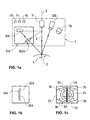
- FIG. 5 shows a further embodiment of the shown ophthalmic device 1, which a view image 3A with a supervision of the eye 3 enables.
- the beam 2 of the light projector 11 by the Cross-sectional part 4 runs and the optical axis of the Image capturing device 12B for capturing the view image 3A together.
- This is achieved, for example, in that the Image capturing device 12B and the light projector 11 thus arranged that their optical axes lie in a common plane, where the beam 2 of the light projector 11 by means of the beam deflecting optical element 121 C, on the optical axis of the Image capture device 12B is steered.
- FIG. 6 shows a further embodiment of the shown ophthalmic device 1, which a view image 3A with a supervision of the eye 3 enables and in which the by Cross-sectional part 4 extending beams 2 and the optical axis of the Image capturing means for capturing the view image 3A coincide.
- the Embodiment according to Figure 6, however, has the advantage over that of Figure 5 that both the cross-sectional image 30A and the view image 3A by means of a single common image converter 120 be recorded.
- FIG. 1 shows a further embodiment of the shown ophthalmic device 1, which a view image 3A with a supervision of the eye 3 enables and in which the by Cross-sectional part 4 extending beams 2 and the optical axis of the Image capturing means for capturing the view image 3A coincide.
- the Embodiment according to Figure 6 has the advantage over that of Figure 5 that both the cross-sectional image 30A and the view image 3A by means of a single common image converter 120 be recorded.
- FIG. 1 shows a further embodiment
- the Light rays for generating the view image 3A from the top view by means of the beam-deflecting optical element 121D which is in the optical axis of the Light projector 11 is arranged by means of the imaging optical elements 122C and by means of the beam deflecting optical element 121 E Image converter 120 is supplied.
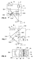
- FIG. 7 shows a further embodiment of the shown ophthalmic device 1, which a view image 3A with a supervision of the eye 3 enables and in which the by Cross-sectional part 4 extending beams 2 and the optical axis of the Image capturing means for capturing the view image 3A coincide.
- the Embodiment according to FIG. 7 has the advantage over that of Figure 5 that both the cross-sectional image 30A and the view image 3A by means of a single common image converter 120 be recorded. Compared to the embodiment according to FIG. 6, it points also the advantage that it is easier and more compact to carry out.
- the embodiment according to FIG. 7 has the advantage over that of Figure 5 that both the cross-sectional image 30A and the view image 3A by means of a single common image converter 120 be recorded. Compared to the embodiment according to FIG. 6, it points also the advantage that it is easier and more compact to carry out.
- FIG. 8 shows the combined cross-sectional image 30A and View image 3A shown by imager 120 of FIG Embodiments according to Figures 6 and 7 is detected.
- the combined Image can be generated as shown in Figure 8 by the Cross-sectional image 30A and view image 3A separated side by side be recorded.
- the cross-sectional image 30A and the view image 3A can with the help of color filters, for example from color cameras are known, and several light sources with different colors, however also partially or completely superimposed. An image separation is then carried out by the processing means 13 on the basis of the colors.
- Shutters optical or electrical closures
- the cross-sectional image 30A and the view image 3A quickly to be captured as separate images in succession, so that Relative movements between eye 3 and ophthalmic device 1 have no noticeable influence.
- image converters with fields and pulsed light sources can do that Cross-sectional image 30A and the view image 3A synchronized in succession are captured as two fields.
- FIG. 9 shows a further embodiment of the ophthalmological device 1, which enables a view image 3A with a view of the eye 3 and in which the beam 2 running through the cross-sectional part 4 and the optical axis of the image acquisition means for acquiring the view image 3A coincide.
- the embodiment according to FIG. 9 results from a further development of the embodiment according to FIG. 7, the ophthalmological device 1 being provided with further imaging optical elements 122B and a further beam-deflecting optical element 121B in order to additionally acquire a second cross-sectional image 30B.
- the imaging optical elements 122A and the beam-deflecting optical element 121A guide the light beams for acquiring the cross-sectional image 30A from a first position at the observation angle ⁇ A for acquisition to the image converter 120.
- the additional imaging optical elements 122B and the additional beam-deflecting optical element 121B guide them Light beams for acquiring the cross-sectional image 30B from a second position at the observation angle ⁇ B for acquisition also at the image converter 120.
- the two positions are preferably on different sides of the beam 2 and the amounts of the observation angles ⁇ A and ⁇ B are preferably of the same size.
- the corneal thickness D can be determined more precisely by averaging from the measured values D A and D B , as described in the European patent application No. 02405272, which was unpublished at the time of filing.
- FIG. 10 shows the combined cross-sectional image 30A, View image 3A and cross-sectional image 30B shown by the Image converter 120 of the embodiments according to FIG. 9 is detected.
- the Combined image can be generated as shown in Figure 10 by the cross-sectional image 30A, the view image 3A and the cross-sectional image 30B can be recorded separately from one another.
- the combined image can however, they can also be recorded and presented differently, such as in connection with Figure 8 has already been mentioned.
- the expert can do other things Make picture arrangements and, for example, the two Cross-sectional images 30A, 30B directly side by side over the view image 3A represent.
- the functional modules of the processing means 13 also include programmed evaluation modules, for example measurement modules, which determine eye structures in the captured and stored cross-sectional images 30A, 30B, in particular images of the cornea with the front corneal surface 31A, 31B and the rear corneal surface 32A, 32B, and based thereon Determine distances and thicknesses, in particular the measured values D A and D B of the distances between the front corneal surface 31A, 31B and the rear corneal surface 32A, 32B for determining the corneal thickness D.
- programmed evaluation modules for example measurement modules, which determine eye structures in the captured and stored cross-sectional images 30A, 30B, in particular images of the cornea with the front corneal surface 31A, 31B and the rear corneal surface 32A, 32B, and based thereon Determine distances and thicknesses, in particular the measured values D A and D B of the distances between the front corneal surface 31A, 31B and the rear corneal surface 32A, 32B for determining the corneal thickness D.
- the opthalmological Device 1 is preferably designed as a compact measurement sample, wherein additional processing equipment for comprehensive coverage of the whole Eye 3 in an external processing unit, for example in one Personal computer, can be executed, the data exchange via a contact-based or contactless communication link is established.
- Certain measurement results for example the local corneal thickness D or - topography, can be on the display 14 or on a display of the external Processing unit are displayed.
Landscapes
- Health & Medical Sciences (AREA)
- Life Sciences & Earth Sciences (AREA)
- Physics & Mathematics (AREA)
- Engineering & Computer Science (AREA)
- Medical Informatics (AREA)
- Animal Behavior & Ethology (AREA)
- Biomedical Technology (AREA)
- Heart & Thoracic Surgery (AREA)
- Biophysics (AREA)
- Molecular Biology (AREA)
- Surgery (AREA)
- Ophthalmology & Optometry (AREA)
- General Health & Medical Sciences (AREA)
- Public Health (AREA)
- Veterinary Medicine (AREA)
- General Physics & Mathematics (AREA)
- Computer Vision & Pattern Recognition (AREA)
- Eye Examination Apparatus (AREA)
Abstract
Description
Die vorliegende Erfindung betrifft eine opthalmologische Vorrichtung und ein opthalmologisches Messverfahren. Die Erfindung betrifft insbesondere eine opthalmologische Vorrichtung und ein opthalmologisches Messverfahren, in welchen mittels eines Lichtprojektors ein Strahlenbündel durch einen Querschnittsteil eines Auges projiziert wird, insbesondere durch einen Querschnittsteil der Hornhaut, in welchen mittels erster Bilderfassungsmittel, die in Scheimpfluganordnung zum Strahlenbündel angeordnet sind, ein Querschnittabbild von mindestens einem Teilgebiet des durch den Lichtprojektor beleuchteten Querschnittsteils aus einer ersten Position ausserhalb des Strahlenbündels erfasst und gespeichert wird, und in welchen mittels zweiter Bilderfassungsmittel ein Ansichtabbild des Auges erfasst und dem erfassten Querschnittabbild zugeordnet gespeichert wird.The present invention relates to an ophthalmic device and an opthalmological measurement method. The invention relates in particular an ophthalmic device and an ophthalmic measuring method, in which a beam of light through a Cross-sectional part of an eye is projected, in particular by a Cross-sectional part of the cornea, in which by means of first image acquisition means, which are arranged in a Scheimpflug arrangement to form a beam Cross-sectional image of at least a partial area of the through the Light projector illuminated part of the cross section from a first position is recorded and stored outside the beam, and in which captured a view image of the eye by means of second image capturing means and stored in association with the captured cross-sectional image.
Im Stand der Technik sind opthalmologische Vorrichtungen und opthalmologische Messverfahren bekannt, in welchen mittels eines Lichtprojektors ein Strahlenbündel durch einen Querschnittsteil eines Auges, insbesondere durch einen Querschnittsteil der Hornhaut, projiziert wird. Typischerweise wird das Strahlenbündel in Form eines Lichtspalts projiziert. In der Patentschrift US 5404884 werden ein Verfahren und eine Vorrichtung für die Untersuchung von Hornhautgewebe eines Patienten beschrieben. Gemäss US 5404884 wird ein im Wesentlichen ebener Laserstrahl mit einem spaltförmigen Profil durch einen Querschnittsteil der Hornhaut projiziert. Durch die Erfassung von mindestens einem Teil des in der Hornhaut gestreuten Lichts, das heisst von mindestens einem Teil des Lichtspalts, wird gemäss US 5404884 ein Querschnittabbild der Hornhaut gewonnen. Aus mehreren solchen Querschnittabbildern der Hornhaut können gemäss US 5404884 Hornhauttrübungen, Hornhautdicke und Hornhauttopografie umfassend für die gesamte Hornhaut bestimmt werden. Da sich die Augen relativ zu der Untersuchungsvorrichtung bewegen können, kann die Untersuchung des gesamten Auges gemäss US 5404884 zu Ungenauigkeiten führen, weil diese Relativbewegungen nicht erfasst und berücksichtigt werden. Im Fachartikel B. R. Masters et al. ,"Transformation of a Set of Slices Rotated on a Common Axis to a Set of Z-Slices: Application to Three-Dimensional Visualization of the In Vivo Human Lens", Computerized Medical Imaging and Graphics, Vol. 21, No. 3, Seiten 145 bis 151, 1997, wird überdies explizit darauf hingewiesen, dass sich bei umfassender Untersuchung des Auges, die auf der Zusammenfügung von mehreren Querschnittabbildern basiert, bedingt durch die Schwierigkeit der gegenseitigen Ausrichtung der einzelnen Querschnittabbilder Messartefakte ergeben können.In the prior art, ophthalmic devices and known ophthalmic measuring methods, in which by means of a Light projector projecting a beam of light through a cross-sectional portion of an eye, in particular through a cross-sectional part of the cornea. The beam is typically projected in the form of a light gap. In the patent US 5404884 a method and an apparatus for described the examination of a patient's corneal tissue. According to US 5404884 describes an essentially flat laser beam with a slit-shaped profile projected through a cross-sectional part of the cornea. By the detection of at least a part of the scattered in the cornea According to US, light, i.e. from at least part of the light gap, is used 5404884 obtained a cross-sectional image of the cornea. From several of them Cross-sectional images of the cornea can be according to US 5404884 Corneal opacities, corneal thickness and corneal topography comprehensive for the entire cornea can be determined. Since the eyes are relative to the Examination device can move, the examination of the entire eye according to US 5404884 lead to inaccuracies because of this Relative movements are not recorded and taken into account. In technical article B. R. Masters et al. , "Transformation of a Set of Slices Rotated on a Common Axis to a Set of Z-Slices: Application to Three-Dimensional Visualization of the In Vivo Human Lens, "Computerized Medical Imaging and Graphics, Vol. 21, No. 3, pages 145 to 151, 1997, it is explicitly pointed out that itself upon extensive examination of the eye based on the reassembly based on several cross-sectional images, due to the difficulty of the mutual alignment of the individual cross-sectional images measurement artifacts can result.
In der Patentschrift US 4711541 wird eine opthalmologische Vorrichtung beschrieben, die über eine Spaltlampe zur Projektion eines Lichtspalts auf die Linse eines Auges verfügt. Die Vorrichtung gemäss US 4711541 umfasst zudem eine Fotokamera, die bezüglich der Ebene des Lichtspalts gemäss Scheimpflugbedingungen angeordnet ist, um den gesamten Querschnittsteil der Augenlinse, der durch den Lichtspalt beleuchtet wird, scharf abzubilden. Die Vorrichtung gemäss US 4711541 verfügt über ein Stereomikroskop, um dem Benutzer eine Aufsicht auf das Auge zu ermöglichen. Mittels optischer Elemente der Vorrichtung kann die Aufsicht zur Abbildung der Fotokamera zugeführt werden. Dabei wird jedoch mittels Polarisationsfiltern sichergestellt, dass nicht der auf der Oberfläche der Augenlinse reflektierte Lichtspalt, sondern nur die in der Aufsicht sichtbare Hintergrundbeleuchtung des Auges, die von der Reflektion des Lichtspalts am Augenhintergrund und der Streuung durch die Augenlinse herrührt, der Fotokamera zur Abbildung zugeführt wird. Mittels eines beweglichen Spiegels können der Lichtschnitt in der Augenlinse und die Aufsicht des Auges mit der Hintergrundbeleuchtung nebeneinander auf dieselbe Fotografie abgebildet werden. Da die Vorrichtung gemäss US 4711541 nur eine Untersuchung mit Einzelbildern ermöglicht, kann keine zusammenhängende Untersuchung des gesamten Auges durchgeführt werden.In US 4711541 an opthalmological Device described, via a slit lamp for projecting a Light gap on the lens of an eye. The device according to US 4711541 also includes a photo camera that is related to the plane of the Light gap is arranged according to Scheimpflug conditions to the entire Cross-sectional part of the eye lens, which is illuminated by the light gap, to depict sharply. The device according to US 4711541 has a Stereo microscope to give the user a top view of the eye enable. By means of optical elements of the device, the supervision can Illustration of the photo camera are fed. However, means Polarization filters ensure that not the one on the surface of the Eye lens reflected light gap, but only the one visible in the top view Backlighting of the eye caused by the reflection of the light gap on Background of the eye and the scattering through the lens of the eye results from the Photo camera is fed for imaging. Using a movable mirror the light section in the eye lens and the eye supervision with the Backlight mapped onto the same photograph side by side become. Since the device according to US 4711541 only has one examination Individual images, no coherent examination of the entire eye.
In der Patentschrift US 5341180 wird eine opthalmologische Bildaufnahmevorrichtung beschrieben, welche mittels einer Spaltlampe ein Lichtspalt auf ein Auge projiziert. Die Bildaufnahmevorrichtung umfasst eine CCD-Kamera (Charged Coupled Device) welche zur Ebene des Lichtspalts entsprechend Scheimpflugbedingungen angeordnet ist, um den gesamten Querschnittsteil des Auges, der durch den Lichtspalt beleuchtet wird, scharf abzubilden. Die Vorrichtung gemäss US 5341180 umfasst eine zweite CCD-Kamera, die dem Benutzer eine Aufsicht auf das zu untersuchende Auge gewährt und zur Ausrichtung der Vorrichtung respektive des Auges mit Hilfe von auf das Auge projizierten Lichtmarken dient. Die Vorrichtung gemäss US 5341180 verfügt über Polarisationsfilter, um zu verhindern, dass der Lichtspalt in der Aufsicht der zweiten CCD-Kamera sichtbar ist. Um präzise Ausrichtungen zu ermöglichen, muss der zu untersuchende Patient bei jeder Aufnahme seine Augen auf Fixiermarken fokussieren, was bei einer Untersuchung des gesamten Auges vom Patienten als mühsam empfunden werden kann und auch zeitaufwendig ist.In US 5341180 an ophthalmic Image recording device described, which by means of a slit lamp Projected light gap on one eye. The image recording device comprises one CCD camera (Charged Coupled Device) to the level of the light gap is arranged according to Scheimpflug conditions to the entire Cross-sectional part of the eye that is illuminated by the light gap, sharp map. The device according to US 5341180 comprises a second CCD camera, which gives the user supervision of the eye to be examined granted and to align the device or the eye with the help of light marks projected onto the eye. The device according to US 5341180 has polarization filters to prevent the light gap is visible in the supervision of the second CCD camera. For precise alignments To enable, the patient to be examined must Focus eyes on fixation marks, which is what an examination of the whole eye can be perceived by the patient as troublesome and is also time consuming.
Es ist eine Aufgabe der vorliegenden Erfindung, eine neue opthalmologische Vorrichtung und ein neues opthalmologisches Messverfahren vorzuschlagen, welche nicht die Nachteile des Stand der Technik aufweisen und die insbesondere eine zusammenhängende Untersuchung des gesamten Auges ermöglichen, insbesondere die Bestimmung von Topografie und Messwerten von Strukturen der Vorderkammer des Auges, beispielsweise die Hornhauttopografie und -dicke, wobei Relativbewegungen des Auges zur Vorrichtung berücksichtigt werden.It is an object of the present invention, a new one ophthalmic device and a new ophthalmic measuring method propose which do not have the disadvantages of the prior art and in particular a coherent investigation of the whole Enable eye, in particular the determination of topography and Measured values of structures of the anterior chamber of the eye, for example the Corneal topography and thickness, with relative movements of the eye to Device are taken into account.
Gemäss der vorliegenden Erfindung werden diese Ziele insbesondere durch die Elemente der unabhängigen Ansprüche erreicht. Weitere vorteilhafte Ausführungsformen gehen ausserdem aus den abhängigen Ansprüchen und der Beschreibung hervor.According to the present invention, these goals are particularly achieved through the elements of the independent claims. More beneficial Embodiments also go from the dependent claims and the description.
Die opthalmologische Vorrichtung umfasst einen ersten Lichtprojektor zur Projektion eines Strahlenbündels durch einen Querschnittsteil eines Auges, insbesondere durch einen Querschnittsteil der Hornhaut des Auges, erste Bilderfassungsmittel zur Erfassung und Speicherung eines Querschnittabbilds von mindestens einem Teilgebiet des durch den ersten Lichtprojektor beleuchteten Querschnittsteils, aus einer ersten Position ausserhalb des Strahlenbündels, welche in Scheimpfluganordnung zum Strahlenbündel angeordnet sind, und zweite Bilderfassungsmittel zur Erfassung eines Ansichtabbilds des Auges und zur Speicherung des erfassten Ansichtabbilds zugeordnet zum erfassten Querschnittabbild.The ophthalmic device comprises a first one Light projector for projecting a beam through a cross-section an eye, in particular through a cross-sectional part of the cornea Eye, first image capturing means for capturing and storing a Cross-sectional image of at least a portion of the through the first Light projector illuminated part of the cross section, from a first position outside the beam, which is arranged in a Scheimpflug arrangement Beams are arranged, and second image capturing means for capturing a view image of the eye and for storing the captured View image assigned to the captured cross-sectional image.
Die oben genannten Ziele werden durch die Erfindung insbesondere dadurch erreicht, dass die zweiten Bilderfassungsmittel dieser opthalmologischen Vorrichtung eingerichtet sind zur Erfassung und Speicherung des Ansichtabbilds derart, dass das Ansichtabbild ein Abbild des durch den ersten Lichtprojektor beleuchteten Querschnittsteils umfasst, und dass diese opthalmologische Vorrichtung Verarbeitungsmittel umfasst zur Positionierung des gespeicherten Querschnittabbilds relativ zum Auge auf der Basis des zugeordnet gespeicherten Ansichtabbilds. Die Erfassung und Speicherung des Querschnittabbilds und des dazu gehörenden Ansichtabbilds mit dem beleuchteten Querschnittsteil ermöglicht die Bestimmung der Position des Querschnittabbilds respektive des darin erfassten beleuchteten Querschnittsteils relativ zum Auge auf der Basis des zugeordneten Ansichtabbilds, was wiederum eine zusammenhängende Untersuchung des gesamten Auges mit mehreren Querschnittabbildern ermöglicht, wobei Relativbewegungen des Auges auf Grund der bestimmten Positionen der betreffenden Querschnittabbilder berücksichtigt werden können. Als Bezugspunkte für die Positionsbestimmung können natürliche Merkmale des Auges wie Limbus, Iris oder Pupille, verwendet werden, die im Ansichtabbild abgebildet sind. Da zu jedem Querschnittabbild automatisch auch die relative Position bestimmt wird, kann das gesamte Auge zusammenhängend untersucht werden, indem mehrere Querschnittabbilder entsprechend ihrer zugeordneten Position zu einem dreidimensionalen Abbild des Auges zusammengefügt werden. Es wird eine zusammenhängende Untersuchung des gesamten Auges ermöglicht, bei der Relativbewegungen des Auges zur Vorrichtung berücksichtigt werden, ohne dass der zu untersuchende Patient bei jeder Aufnahme seine Augen auf Fixiermarken fokussieren muss, um Messfehler zu vermeiden. Aus mehreren Querschnittabbildern, die entsprechend ihrer bestimmten Position zusammengefügt werden, können beispielsweise Hornhautdicke, Hornhauttopografie und/oder Hornhauttrübungen umfassend für die gesamte Hornhaut des Auges bestimmt werden. Die Verarbeitungsmittel sind vorzugsweise eingerichtet zur Positionierung mehrerer gespeicherter Querschnittabbilder relativ zueinander auf der Basis der ihnen jeweils zugeordneten gespeicherten Ansichtabbilder.The above objectives are particularly noticeable by the invention achieved in that the second imaging means of this ophthalmic device are set up for detection and Storage of the view image in such a way that the view image is an image of the cross-section part illuminated by the first light projector, and that this ophthalmic device includes processing means for Positioning the saved cross-sectional image relative to the eye on the Basis of the assigned saved view image. The capture and Storage of the cross-sectional image and the associated view image With the illuminated cross-section, the position can be determined the cross-sectional image or the illuminated cross-sectional part captured therein relative to the eye based on the assigned view image, which in turn is a coherent examination of the entire eye with several cross-sectional images, the relative movements of the Eye based on the determined positions of the relevant cross-sectional images can be taken into account. As reference points for the Positioning can use natural features of the eye such as limbus, iris or pupil can be used, which are shown in the view image. To the relative position is automatically determined for each cross-sectional image, the entire eye can be examined contiguously by several cross-sectional images according to their assigned position a three-dimensional image of the eye. It will enables a coherent examination of the entire eye at the relative movements of the eye to the device are taken into account without that the patient to be examined opens his eyes every time he takes a picture Focusing marks must be focused to avoid measurement errors. From several Cross-sectional images that correspond to their specific position can be joined together, for example corneal thickness, Comprehensive corneal topography and / or corneal opacity for the entire Cornea of the eye can be determined. The processing means are preferably set up for positioning several stored Cross-sectional images relative to each other based on each of them associated saved view images.
In einer Ausführungsvariante sind die Verarbeitungsmittel eingerichtet zum Bestimmen der Dicke des durch den ersten Lichtprojektor beleuchteten Querschnittsteils des Auges auf der Basis des gespeicherten Ansichtabbilds. Da das vom ersten Lichtprojektor projizierte Strahlenbündel eine endliche Dicke aufweist und divergent sein kann, erscheint die Dicke des beleuchteten Querschnittsteils im ausserhalb des Strahlenbündels erfassten Querschnittabbild abhängig von der Dicke des Strahlenbündels grösser oder kleiner. Die Bestimmung der Dicke des durch den ersten Lichtprojektor beleuchteten Querschnittsteils des Auges hat den Vorteil, dass der Einfluss der endlichen Dicke des Strahlenbündels bei der Dickenmessung von beleuchteten Querschnittsteilen des Auges, beispielsweise bei der Hornhautdickenmessung, berücksichtigt und die Dickenmessung entsprechend korrigiert werden kann, was zu höherer Messgenauigkeit führt. Für die Bestimmung der Dicke des durch den ersten Lichtprojektor beleuchteten Querschnittsteils respektive des Strahlenbündels erweist sich ein Aufsichtabbild, also ein Ansichtabbild, bei dem die zweiten Bilderfassungsmittel so angeordnet werden, dass ihre optische Achse im Wesentlichen parallel zu der optischen Achse oder der Sehachse des Auges verläuft oder mit der optischen Achse oder der Sehachse des Auges zusammenfällt, als besonders vorteilhaft, weil besonders genau und einfach, wenn die optische Achse der zweiten Bilderfassungsmittel mit dem durch den Querschnittsteil verlaufenden Strahlenbündel zusammenfällt.The processing means are in an embodiment variant set up to determine the thickness of the through the first light projector illuminated cross-sectional part of the eye based on the stored View image. Because the beam of light projected by the first light projector has a finite thickness and can be divergent, the thickness of the illuminated cross-section in the outside of the beam Cross-sectional image larger or larger depending on the thickness of the beam smaller. Determining the thickness of the through the first light projector Illuminated cross section of the eye has the advantage that the influence of the finite thickness of the beam when measuring the thickness of illuminated Cross-sectional parts of the eye, for example when measuring corneal thickness, taken into account and the thickness measurement can be corrected accordingly, which leads to higher measuring accuracy. For determining the thickness of the through the first light projector illuminated cross-section or respectively A bundle of rays turns out to be a top view image, i.e. a view image in which the second image capturing means are arranged so that their optical Axis substantially parallel to the optical axis or the visual axis of the Eye runs or with the optical axis or the visual axis of the eye coincides as particularly advantageous because it is particularly precise and simple, if the optical axis of the second image capturing means corresponds to that of the Cross-sectional beam coincides.
Die bevorzugte Anordnung der zweiten Bilderfassungsmittel und des ersten Lichtprojektors, in welcher die optische Achse der zweiten Bilderfassungsmittel mit dem durch den Querschnittsteil verlaufenden Strahlenbündel zusammenfällt, ermöglicht in vorteilhafter Weise auch eine besonders einfache und genaue Positionsbestimmung des abgebildeten beleuchteten Querschnittsteils, insbesondere wenn das Auge durch die zweiten Bilderfassungsmittel als Aufsichtabbild erfasst wird. The preferred arrangement of the second imaging means and the first light projector, in which the optical axis of the second Image acquisition means with the one running through the cross-sectional part Beam bundle coincides, advantageously also enables one particularly simple and precise position determination of the depicted illuminated cross-section, especially when the eye through the second Image acquisition means is recorded as a top view image.
In einer bevorzugten Ausführungsvariante sind die ersten und die zweiten Bilderfassungsmittel so angeordnet, dass ihre optischen Achsen in einer gemeinsamen Ebene liegen. Durch diese Anordnung können die durch ersten Bilderfassungsmittel erfassten Querschnittabbilder und die durch zweiten Bilderfassungsmittel erfassten zugeordneten Ansichtabbilder geometrisch einfacher zueinander in Bezug gebracht werden, als dies bei alternativen Anordnungen möglich ist, was die relative Positionierung mehrerer Querschnittabbilder untereinander und das Zusammenfügen dieser Querschnittabbilder vereinfacht.In a preferred embodiment, the first and the second imaging means arranged so that their optical axes in lie on a common level. With this arrangement, the through first image acquisition means captured cross-sectional images and the by second image acquisition means captured associated view images geometrically easier to relate to each other than this alternative arrangements is possible, which is the relative positioning of several Cross-sectional images with each other and the assembly of these Cross-sectional images simplified.
Vorzugsweise umfassen die ersten und die zweiten Bilderfassungsmittel einen gemeinsamen Bildwandler und die ersten Bilderfassungsmittel umfassen strahlumlenkende optische Elemente, wobei die strahlumlenkenden optischen Elemente so angeordnet sind, dass Lichtstrahlen zur Erzeugung des Querschnittabbilds zum gemeinsamen Bildwandler umgelenkt werden. In einer alternativen Ausführungsvariante umfassen die ersten und zweiten Bilderfassungsmittel einen gemeinsamen Bildwandler und die zweiten Bilderfassungsmittel umfassen strahlumlenkende optische Elemente, wobei die strahlumlenkenden optischen Elemente so angeordnet sind, dass Lichtstrahlen zur Erzeugung des Ansichtabbilds zum gemeinsamen Bildwandler umgelenkt werden. Beide dieser Ausführungsvarianten haben den Vorteil, dass sie nur einen Bildwandler aufweisen und somit kostengünstiger und kompakter ausgeführt werden können, als eine alternative Ausführung mit zwei separaten Bildwandlern. Die erstangeführte bevorzugte dieser beiden Ausführungsvarianten weist überdies den Vorteil auf, dass die ersten Bilderfassungsmittel auf einfache und kompakte Weise mit weiteren strahlumlenkenden optischen Elementen versehen werden können, so dass Lichtstrahlen zur Erzeugung mehrerer Querschnittabbilder aus verschiedenen Positionen zum gemeinsamen Bildwandler umgelenkt werden können.Preferably comprise the first and the second Image acquisition means a common image converter and the first Image acquisition means comprise beam-deflecting optical elements, the beam-deflecting optical elements are arranged so that light rays to generate the cross-sectional image for the common image converter be redirected. In an alternative embodiment variant, the first and second image acquisition means a common image converter and the second image acquisition means comprise beam-deflecting optical ones Elements, the beam-deflecting optical elements arranged in this way are that light rays for generating the view image for common Image converter are redirected. Both of these variants have the The advantage that they have only one image converter and thus less expensive and can be made more compact than an alternative version with two separate image converters. The first preferred preferred of these two Design variants also has the advantage that the first Image acquisition means in a simple and compact way with others beam-deflecting optical elements can be provided so that Light beams to create multiple cross-sectional images from different ones Positions can be redirected to the common image converter.
Die ersten Bilderfassungsmittel sind vorzugsweise eingerichtet zur Erfassung und Speicherung eines zweiten Querschnittabbilds des Teilgebiets des durch den ersten Lichtprojektor beleuchteten Querschnittsteils aus einer zweiten Position ausserhalb des Strahlenbündels, gleichzeitig mit der Erfassung des ersten Querschnittabbilds, wobei die erste Position und die zweite Position auf verschiedenen Seiten einer im Strahlenbündel liegenden Ebene liegen und den beleuchteten Querschnittsteil beispielsweise unter einem gleich grossen Beobachtungswinkel erfassen. Der Vorteil, Abbilder des beleuchteten Querschnittsteils aus mehreren Positionen zu erfassen, besteht darin, dass mehrere Messwerte bestimmt und daraus durch Mittelwertbildung genauere Messresultate bestimmt werden können. Bei der Mittelwertbildung heben sich beispielsweise Abweichungen bei der Bestimmung einer ersten Distanz zwischen Augenstrukturen im ersten Querschnittabbild und einer zweiten Distanz zwischen Augenstrukturen im zweiten Querschnittabbild gegenseitig auf. Wenn folglich die opthalmologische Vorrichtung so angewendet wird, dass das Strahlenbündel im Wesentlichen senkrecht zu der dem Lichtprojektor zugewandten (Hornhaut-) Oberfläche des Auges projiziert wird, wirken sich geringe Verkippungen des Strahlenbündels bezüglich der Normalen zu der dem Lichtprojektor zugewandten Oberfläche der Hornhaut beispielsweise nicht auf die Bestimmung der Hornhautdicke aus. Auch wenn die Vorrichtung so angewendet wird, dass das Strahlenbündel im Wesentlichen entlang der optischen Achse des Auges projiziert wird, wirken sich geringe Verkippungen und Exzentrizitäten des Strahlenbündels, das heisst Verschiebungen vom Scheitelpunkt des Auges, nicht auf die Bestimmung der Hornhautdicke aus. Dasselbe trifft auf kleine Abweichungen des Beobachtungswinkels aus der ersten Position vom Beobachtungswinkels aus der zweiten Position zu. Der Vorteil, zwei Querschnittabbilder aus verschiedenen Positionen unter gleichen Beobachtungswinkeln zu erfassen, besteht also darin, dass sich kleine Ungenauigkeiten bei der Applikation, der Justierung und/oder der Kalibrierung der opthalmologischen Vorrichtung ohne grosse Abweichungen auf die Messresultate auswirken. Wird die opthalmologische Vorrichtung beispielsweise in Meridianschnitten appliziert, dann reicht eine Kalibrierung im Meridianschnitt aus, um auch bei leichten Exzentrizitäten und Verkippungen genau messen zu können. Die opthalmologische Vorrichtung ermöglicht so eine einfachere Applikation und Ausführung unter Beibehaltung der Genauigkeit der Messresultate.The first image acquisition means are preferably set up for Acquisition and storage of a second cross-sectional image of the sub-area of the cross-sectional part illuminated by the first light projector from one second position outside the beam, simultaneously with the Acquisition of the first cross-sectional image, the first position and the second position on different sides of one lying in the beam Lay level and the illuminated cross section, for example, under one Capture equally large viewing angles. The advantage of images of the to capture the illuminated cross-section from several positions in that several measured values are determined and averaged from them more accurate measurement results can be determined. When averaging for example, there are deviations when determining a first one Distance between eye structures in the first cross-sectional image and one second distance between eye structures in the second cross-sectional image each other. If consequently the ophthalmic device is applied in this way is that the beam of rays is substantially perpendicular to that of the Light projector facing (corneal) surface of the eye is projected, there are slight tilting of the beam with respect to the normal to the surface of the cornea facing the light projector for example, not to determine the thickness of the cornea. Even if the device is applied so that the beam of rays is essentially projected along the optical axis of the eye, minor effects Tilting and eccentricities of the beam, that is Shifts from the vertex of the eye, not to the determination of the Corneal thickness. The same applies to small deviations from the Observation angle from the first position from the observation angle to the second position. The advantage of having two cross-sectional images to capture different positions at the same observation angles, is that there are small inaccuracies in the application, the Adjustment and / or calibration of the ophthalmic device without large deviations affect the measurement results. Will the ophthalmic device applied, for example, in meridian sections, then a calibration in the meridian section is sufficient to also with slight eccentricities and to be able to measure tilting precisely. The opthalmological device thus enables easier application and Execution while maintaining the accuracy of the measurement results.
In der Ausführungsvariante, in der die ersten Bilderfassungsmittel einen Bildwandler und weitere strahlumlenkende optische Elemente umfassen, sind vorzugsweise erste der strahlumlenkenden optischen Elemente so bei der ersten Position angeordnet, dass Lichtstrahlen zur Erzeugung des ersten Querschnittabbilds zum Bildwandler umgelenkt werden, und zweite der strahlumlenkenden optischen Elemente sind so bei der zweiten Position angeordnet, dass Lichtstrahlen zur Erzeugung des zweiten Querschnittabbilds zum Bildwandler umgelenkt werden. Diese ergibt eine besonders kompakte und kostengünstige Ausführung.In the embodiment variant in which the first image capturing means comprise an image converter and further beam-deflecting optical elements, are preferably the first of the beam deflecting optical elements arranged first position that light beams for generating the first Cross-sectional image are redirected to the image converter, and the second beam-deflecting optical elements are in the second position arranged that light beams for generating the second cross-sectional image be redirected to the image converter. This results in a particularly compact and inexpensive execution.
In einer Ausführungsvariante umfasst die opthalmologische Vorrichtung einen oder mehrere zusätzliche zweite Lichtprojektoren zur Projektion von Lichtmarken auf das Auge und die zweiten Bilderfassungsmittel sind so mit dem ersten Lichtprojektor und mit den zweiten Lichtprojektoren synchronisiert, dass bei der Erfassung und Speicherung des Ansichtabbilds des Auges, das Abbild des durch den ersten Lichtprojektor beleuchteten Querschnittsteils und ein Abbild der durch die zweiten Lichtprojektoren projizierten Lichtmarken miterfasst und mitgespeichert werden. Die projizierten und miterfassten Lichtmarken dienen als künstliche Referenzmarken, die zur Bestimmung der relativen Position der opthalmologischen Vorrichtung zum Auge und damit zur Positionsbestimmung des Querschnittabbilds respektive des beleuchteten Querschnittsteils verwendet werden können.In one embodiment, the opthalmological includes Device one or more additional second light projectors Projection of light marks on the eye and the second image capturing means are with the first light projector and with the second light projectors synchronizes that when capturing and storing the view image of the Eye, the image of the cross-sectional part illuminated by the first light projector and an image of those projected by the second light projectors Light marks are also recorded and saved. The projected and co-registered light marks serve as artificial reference marks which are used for Determination of the relative position of the ophthalmic device for Eye and thus for determining the position of the cross-sectional image, respectively of the illuminated cross-section can be used.
In einer Ausführungsvariante umfasst die opthalmologische Vorrichtung einen Schirmkörper mit einem sichtbaren Muster, welcher Schirmkörper so angeordnet ist, dass das sichtbare Muster bei der Applikation der Vorrichtung auf einer dem Auge zugewandten Seite des Schirmkörpers liegt und dass das Strahlenbündel ungehindert durch den Querschnittsteil des Auges projizierbar ist und dass das Querschnittabbild und das Ansichtabbild ungehindert durch die ersten respektive zweiten Bilderfassungsmittel erfassbar sind. Da das sichtbare Muster, beispielsweise ein Placidomuster, durch das Auge reflektiert wird, kann es mit dem Ansichtabbild erfasst werden und als künstliches Referenzmuster zur Bestimmung der relativen Position der opthalmologischen Vorrichtung zum Auge und damit zur Positionsbestimmung des Querschnittabbilds respektive des beleuchteten Querschnittsteils verwendet werden. In one embodiment, the opthalmological includes Device a screen body with a visible pattern, which Umbrella body is arranged so that the visible pattern during application the device on a side of the screen body facing the eye lies and that the beam of rays is unhindered by the cross-sectional part of the Eye projectable and that the cross-sectional image and the view image unhindered by the first or second image capturing means are. Since the visible pattern, for example a placido pattern, is shown by the Is reflected, it can be captured with the view image and as Artificial reference pattern to determine the relative position of the ophthalmic device for the eye and thus for position determination the cross-sectional image or the illuminated cross-sectional part be used.
In einer Ausführungsvariante umfasst die opthalmologische Vorrichtung Antriebsmittel, um den ersten Lichtprojektor und die ersten und die zweiten Bilderfassungsmittel im Wesentlichen um eine Normale zu der dem ersten Lichtprojektor zugewandten Oberfläche des Auges zu rotieren oder im Wesentlichen senkrecht zu dieser Normalen zu verschieben. Durch diese Antriebsmittel wird eine automatisierte zusammenhängende Untersuchung des gesamten Auges basierend auf mehreren Querschnittabbildern ermöglicht.In one embodiment, the opthalmological includes Device driving means to the first light projector and the first and the second image capturing means essentially a normal to that first light projector facing the surface of the eye to rotate or To move essentially perpendicular to this normal. Through this An automated, coherent investigation of the entire eye based on several cross-sectional images.
Vorzugsweise ist der erste Lichtprojektor so beschaffen, dass er das Strahlenbündel in Form eines Lichtspalts projiziert. Obwohl auch andere Formen des Strahlenbündels verwendbar sind, beispielsweise punktförmig, eignet sich ein Strahlenbündel in Form eines Lichtspalts besonders für die zusammenhängende Untersuchung des gesamten Auges basierend auf mehreren Lichtschnitten des Auges.The first light projector is preferably designed in such a way that it does Beams of rays projected in the form of a light gap. Although others too Shapes of the beam can be used, for example point-like, a bundle of rays in the form of a light gap is particularly suitable for continuous examination of the entire eye based on several light sections of the eye.
Vorzugsweise werden die zweiten Bilderfassungsmittel so angeordnet, dass ihre optische Achse mit der optischen Achse des Auges zusammenfällt oder im Wesentlichen parallel zu der optischen Achse des Auges verläuft. Dadurch kann das Auge als Aufsichtabbild erfasst werden, was sowohl für die Positionsbestimmung des beleuchteten Querschnittsteils als auch für die Dickenbestimmung des beleuchteten Querschnittsteils vorteilhaft ist, wie bereits vorgängig erklärt wurde. In Kombination mit der bevorzugten Anordnung der zweiten Bilderfassungsmittel und des ersten Lichtprojektors, in welcher die optische Achse der zweiten Bilderfassungsmittel mit dem durch den Querschnittsteil verlaufenden Strahlenbündel zusammenfällt, ergibt sich eine Anordnung, in welcher der erste Lichtprojektor das Strahlenbündel so projiziert, dass das Strahlenbündel mit der optischen Achse des Auges zusammenfällt oder dass das Strahlenbündel parallel zu der optischen Achse des Auges verläuft.The second image acquisition means are preferably so arranged that its optical axis with the optical axis of the eye coincides or is substantially parallel to the optical axis of the Eye runs. As a result, the eye can be captured as a top view image both for determining the position of the illuminated cross-section part also advantageous for determining the thickness of the illuminated cross-section is, as previously explained. In combination with the preferred Arrangement of the second image capturing means and the first light projector, in which the optical axis of the second image acquisition means with that through the Cross-sectional part of the bundle of rays coincides, there is a Arrangement in which the first light projector projects the beam of rays so that the bundle of rays coincides with the optical axis of the eye or that the beam is parallel to the optical axis of the eye runs.
Nachfolgend wird eine Ausführung der vorliegenden Erfindung anhand
eines Beispieles beschrieben. Das Beispiel der Ausführung wird durch die
folgenden beigelegten Figuren illustriert:
In den Figuren 1a, 2a, 4, 5, 6, 7 und 9 bezeichnet das
Bezugszeichen 1 eine opthalmologische Vorrichtung, wobei in der
nachfolgenden Beschreibung mit Bezug auf diese Figuren verschiedene
Ausführungsformen der opthalmologischen Vorrichtung 1 erläutert werden.
Ansonsten werden in den Figuren einander entsprechende, gleiche Komponenten
durch gleiche Bezugszeichen bezeichnet.In Figures 1a, 2a, 4, 5, 6, 7 and 9, this denotes
Reference numeral 1 an ophthalmic device, wherein in the
the following description with reference to these figures
Embodiments of the
Die in den Figuren 1 a, 2a, 4, 5, 6, 7 und 9 dargestellten
Ausführungsformen der opthalmologischen Vorrichtung 1 umfassen einen
Lichtprojektor 11 zur Projektion eines Strahlenbündels 2 durch einen
Querschnittsteil eines Auges 3, insbesondere durch einen Querschnittsteil der
Hornhaut 30 des Auges 3. Das Strahlenbündel 2 wird vorzugsweise in der Form
eines Lichtspalts projiziert. Der Lichtprojektor 11 umfasst beispielsweise eine
Spaltlampe oder einen Laser, dessen Licht durch Strahlumformungsoptiken zu
einem Fächer geformt wird.The shown in Figures 1 a, 2a, 4, 5, 6, 7 and 9
Embodiments of the
Die in den Figuren 1 a, 2a, 4, 5, 6, 7 und 9 dargestellten
Ausführungsformen der opthalmologischen Vorrichtung 1 umfassen
Bilderfassungsmittel zur Erfassung und Speicherung eines Querschnittabbilds
30A von mindestens einem Teilgebiet des durch den Lichtprojektor 11
beleuchteten Querschnittsteils 4, welche in Scheimpfluganordnung zum
Strahlenbündel 2 angeordnet sind.The shown in Figures 1 a, 2a, 4, 5, 6, 7 and 9
Embodiments of the
Die in den Figuren 1a, 2a, 4, 5, 6, 7 und 9 dargestellten
Ausführungsformen der opthalmologischen Vorrichtung 1 umfassen zudem
weitere Bilderfassungsmittel zur Erfassung eines Ansichtabbilds 3A des Auges
3, welches ein Abbild des beleuchteten Querschnittsteils 4A umfasst, und zur
Speicherung des erfassten Ansichtabbilds 3A und des darin enthaltenen
Abbilds des beleuchteten Querschnittsteils 4A zugeordnet zum erfassten
Querschnittabbild 30A.Those shown in Figures 1a, 2a, 4, 5, 6, 7 and 9
Embodiments of the
Wie in den Figuren 1a, 2a, 4, 5, 6, 7 und 9 dargestellt ist, umfassen
die Bilderfassungsmittel je nach Ausführungsform der opthalmologischen
Vorrichtung 1 Bilderfassungsvorrichtungen 12A, 12B, zum Beispiel CCD-Kameras
(Charged Coupled Device) oder CMOS-Kameras (Complementary
Metal-Oxide-Silicon), Bildwandler 120, zum Beispiel CCD-Chips oder CMOS-Chips,
strahlumlenkende optische Elemente 121 A, 121 B, 121 E, zum Beispiel
Spiegel, strahlumlenkende optische Elemente 121 C, 121 D, zum Beispiel
strahlteilende optische Elemente wie halbdurchlässige Spiegel, und/oder
abbildende optische Elemente 122A, 122B, 122C, zum Beispiel Linsen.As shown in Figures 1a, 2a, 4, 5, 6, 7 and 9, include
the image capturing means depending on the embodiment of the
Zur Sichtbarmachung von natürlichen Augenmerkmalen, wie Limbus
33, Iris 34 oder Pupille 35, und/oder zur Projektion von künstlichen Lichtmarken
36 umfassen die in den Figuren 1a, 2a, 4, 5, 6, 7 und 9 dargestellten
Ausführungsformen der opthalmologischen Vorrichtung 1 eine oder mehrere
zusätzliche Lichtquellen 16. Insbesondere zur Sichtbarmachung natürlicher
Augenmerkmale können beispielsweise eine oder mehrere Infrarotleuchtdioden
verwendet werden. Die natürlichen und/oder künstlichen Referenzmerkmale
werden im Ansichtabbild 3A des Auges 3 miterfasst.For the visualization of natural eye features such as
Die in den Figuren 1a, 2a, 4, 5, 6, 7 und 9 dargestellten
Ausführungsformen der opthalmologischen Vorrichtung 1 umfassen
Verarbeitungsmittel 13 mit funktionalen Modulen zur Verarbeitung von
erfassten Ansichtabbildern 3A und Querschnittabbildern 30A. Die
Verarbeitungsmittel 13 umfassen mindestens einen Prozessor, Daten- und
Programmspeicher. Die funktionalen Module sind vorzugsweise als
programmierte Softwaremodule ausgeführt, die im Programmspeicher
gespeichert sind und auf dem Prozessor ausgeführt werden. Der Fachmann
wird verstehen, dass die funktionalen Module auch teilweise oder vollständig
hardwaremässig ausgeführt werden können. Those shown in Figures 1a, 2a, 4, 5, 6, 7 and 9
Embodiments of the
Die funktionalen Module der Verarbeitungsmittel 13 umfassen ein
programmiertes Positionierungsmodul, welches die Position eines
gespeicherten Querschnittabbilds 30A relativ zum Auge 3 bestimmt. Die
relative Positionierung erfolgt auf der Basis der Ansichtabbilder 3A, die den
Querschnittabbildern 30A jeweils zugeordnet sind. Die Positionsbestimmung
eines Querschnittabbilds 30A erfolgt durch Positionsbestimmung des Auges 3
relativ zur opthalmologische Vorrichtung 1. Dabei wird die relative Position der
opthalmologischen Vorrichtung 1 zum Auge 3 auf Grund auf Grund des Abbilds
des beleuchteten Querschnittsteils 4A, der natürlichen Merkmale des Auges 3
und/oder der abgebildeten künstlichen Referenzmerkmale, beispielsweise die
abgebildeten Lichtmarken 36, bestimmt. Die Position eines Querschnittabbilds
30A respektive des zugeordneten Abbilds des beleuchteten Querschnittsteils
4A kann mit Bezug zu den natürlichen Merkmalen des Auges 3 definiert
werden, die im betreffenden Ansichtabbild 3A enthalten sind.The functional modules of the processing means 13 comprise a
programmed positioning module, which the position of a
stored
Die funktionalen Module der Verarbeitungsmittel 13 umfassen
zudem ein programmiertes Kompositionsmodul, welches mehrere erfasste und
gespeicherte Querschnittabbilder 30A relativ zueinander positioniert. Das
Kompositionsmodul fügt unter Kenntnis der geometrischen Anordnung der
opthalmologischen Vorrichtung 1 die erfassten und gespeicherten
Querschnittabbilder 30A entsprechend ihrer relativen Position zum Auge 3
respektive zueinander zu einem dreidimensionalen Abbild des Auges 3
zusammen, insbesondere zu einem dreidimensionalen Abbild von
Vorderkammerstrukturen des Auges 3, insbesondere der Hornhaut 30.The functional modules of the processing means 13 comprise
also a programmed composition module, which recorded several and
stored
Die Funktions- und Ablaufsteuerung der opthalmologischen
Vorrichtung 1 kann durch die Verarbeitungsmittel 13 und/oder durch weitere
nicht dargestellte elektronische Steuermodule erfolgen.The functional and sequence control of the
Die elektrische Speisung der opthalmologischen Vorrichtung 1
erfolgt durch eine interne oder durch eine mittels Kabel angeschlossene
externe Energiequelle.The electrical supply of the
Die in den Figuren 1a, 2a, 4, 5, 6, 7 und 9 dargestellten
Ausführungsformen der opthalmologischen Vorrichtung 1 umfassen eine
Anzeige 14, auf welcher bestimmte Messwerte und/oder Applikationshilfen
angezeigt werden.Those shown in Figures 1a, 2a, 4, 5, 6, 7 and 9
Embodiments of the
Die in den Figuren 1a, 2a, 4, 5, 6, 7 und 9 dargestellten
Ausführungsformen der opthalmologischen Vorrichtung 1 umfassen
Antriebsmittel 15 zum Rotieren des Lichtprojektors 11 und der
Bilderfassungsmittel, im Wesentlichen um eine Normale zu der dem
Lichtprojektor 11 zugewandten Oberfläche des Auges 3 oder zum Verschieben
dieser Komponenten im Wesentlichen senkrecht zu dieser Normalen. Wie in
der Figur 9 schematisch dargestellt ist, sind der Lichtprojektor 11 und die
Bilderfassungsmittel 120, 121A, 121B, 121C, 122A, 122B, 122C zu diesem
Zweck an einer beweglichen Trägervorrichtung 10 angebracht, welche durch
die Antriebsmittel 15 angetrieben wird. Die zusätzliche(n) Lichtquelle(n) 16
können an der Trägervorrichtung 10 angebracht sein und mitbewegt werden
oder sie können so an der opthalmologischen Vorrichtung 1 angebracht sein,
dass sie nicht mit den Antriebsmitteln 15 gekoppelt sind. Die Antriebsmittel 15
umfassen vorzugsweise einen Rotationstreiber, beispielsweise ein
Elektromotor, der die Trägervorrichtung 10 um die optische Achse Z des Auges
rotiert. Durch die Rotation des Lichtprojektors 11 und der Bilderfassungsmittel
120, 121A, 121B, 121C, 122A, 122B, 122C um die optische Achse Z wird das
gesamte Auge, insbesondere die gesamte Hornhaut 30 vermessen. In dieser
Konfiguration lassen sich auf Grund der hohen Symmetrie die geringsten
Messunsicherheiten erzielen.Those shown in Figures 1a, 2a, 4, 5, 6, 7 and 9
Embodiments of the
Wie in der Figur 1a dargestellt ist, umfasst die
Bilderfassungsvorrichtung 12A zur Erfassung und Speicherung von
Querschnittabbildern 30A abbildende optische Elemente 122A und einen
Bildwandler 120, welche in Scheimpfluganordnung zum projizierten
Strahlenbündel 2 angeordnet sind. In der Figur 1 b ist ein durch die
Bilderfassungsvorrichtung 12A erfasstes Querschnittabbild 30A des
beleuchteten Querschnittsteils 4 des Auges 3 dargestellt. Weitere Strukturen
des Auges 3, wie Iris oder Linse, sind der Einfachheit halber in der Figur 1b
nicht dargestellt. Im Querschnittabbild 30A sind insbesondere ein
Querschnittabbild der vorderen Hornhautoberfläche 31 A und ein
Querschnittabbild der hinteren Hornhautoberfläche 32A sichtbar. In der
Ausführungsform gemäss Figur 1a befindet sich die optische Achse der
separaten Bilderfassungsvorrichtung 12B zur Erfassung des Ansichtabbilds 3A
des Auges 3 ausserhalb des Strahlenbündels 2. Das in der Figur 1c
dargestellte Ansichtabbild 3A des Auges 3 entspricht allerdings einem
Ansichtabbild, das durch eine Bilderfassungsvorrichtung 12B als Aufsicht
erfasst wird, wobei die Bilderfassungsvorrichtung 12B so angeordnet ist, dass
ihre optische Achse im Wesentlichen parallel zu der optischen Achse Z des
Auges 3 oder der Sehachse des Auges 3 verläuft oder mit der optischen Achse
Z oder der Sehachse des Auges 3 zusammenfällt, was beispielsweise in den
Figuren 4 und 5 dargestellt ist. Im Ansichtabbild 3A sind insbesondere ein
Abbild des beleuchteten Querschnittsteils 4A mit der endlichen Dicke d, die
projizierten Lichtmarken 36 sowie Limbus 33, Iris 34 und Pupille 35 des Auges
3 sichtbar. Lichtmarken sind beispielsweise Glanzlichter von Leuchtdioden oder
aufprojizierte Punkte. Projektionsorte sind beispielsweise die Sklera 37 oder die
Hornhaut 30. Das erfasste Querschnittabbild 30A und das erfasste
Ansichtabbild 3A werden den Verarbeitungsmitteln 13 zugeführt und dort im
Datenspeicher einander zugeordnet gespeichert. Der Lichtprojektor 11 und die
Bilderfassungsmittel 12A, 12B werden durch die Antriebsmittel 15 in weitere
Aufnahmestellungen bewegt und es werden weitere Querschnittabbilder 30A
und Ansichtabbilder 3A erfasst und jeweils einander zugeordnet gespeichert.As shown in FIG. 1a, the
In der Figur 2a wird eine Ausführungsform der opthalmologischen
Vorrichtung 1 dargestellt, welche einen durchbrochenen Schirmkörper 17
umfasst. Die Durchbrechungen 171, 172, 173 des Schirmkörpers 17 sind
jeweils so angeordnet, dass die Strahlengänge zu den Bilderfassungsmitteln
12A, 12B und zum Lichtprojektor 11 den Schirmkörper 17 ungehindert
passieren können. Auf der dem Auge 3 zugewandten Seite des Schirmkörpers
17 ist ein sichtbares Muster 17', ein so genanntes Placidomuster,
beispielsweise mit Kreisringen 174 angebracht, das durch die Oberfläche des
Auges 3 gespiegelt wird, wie beispielsweise von Keratometern bekannt. Auf
dem Schirmkörper 17 können dem Auge 3 zugewandt auch Lichtquellen
angebracht sein, beispielsweise Lichtprojektoren 16 zur Projektion von
Lichtmarken 36. Eine Ansicht der dem Auge 3 zugewandten Seite des
Schirmkörpers 17 mit Durchbrechungen 171, 172, 173 und dem sichtbaren
Muster 17' ist in der Figur 2b dargestellt. Die Spiegelung des sichtbaren
Musters 17' auf der Augenoberfläche wird durch die Bilderfassungsvorrichtung
12B im Ansichtabbild 3A abgebildet und kann bei der Positionierung der
Querschnittabbilder 30A als künstliches Referenzmuster für die Bestimmung
der relativen Position der opthalmologischen Vorrichtung 1 zum Auge 3
verwendet werden. Der Schirmkörper 17 ist vorzugsweise so mit den
Antriebsmitteln 15 verbunden, dass er mit dem Lichtprojektor 11 und den
Bilderfassungsmitteln mitbewegt wird. In einer alternativen Ausführung kann
der Schirmkörper 17 auch so an der opthalmologischen Vorrichtung 1
angebracht sein, dass er nicht mit den Antriebsmitteln 15 gekoppelt ist mit,
wobei die Durchbrechungen 171, 172, 173 entsprechend angepasst sind. An
dieser Stelle soll angeführt werden, dass der Schirmkörper 17 auch so
angeordnet werden kann, dass die Bilderfassungsmittel 12A, 12B und/oder der
Lichtprojektor 11 zwischen den Schirmkörper 17 und das Auge 3 zu liegen
kommen, dabei sind die Bilderfassungsmittel 12A, 12B und/oder der
Lichtprojektor 11 beispielsweise auf der dem Auge 3 zugewandten Seite des
Schirmkörpers 17 angebracht.In Figure 2a is an embodiment of the
Die Figur 3 zeigt eine Schnittansicht eines beleuchteten
Querschnittsteils 4 des Auges 3, insbesondere der Hornhaut 30. In der Figur 3
bezeichnet das Bezugszeichen 31 die vordere Hornhautoberfläche und das
Bezugszeichen 32 die hintere Hornhautoberfläche. Die Hornhaut 30 wird durch
das Strahlenbündel 2 im Querschnittsteil 4 beleuchtet. Wie in der Figur 3
dargestellt wird, weist das Strahlenbündel 2 eine endliche Dicke d auf. Die
reflektierten Lichtstrahlen 21, 22 lassen die Dicke D des beleuchteten
Querschnittsteils 4 in einem Querschnittabbild 30A auf Grund der endlichen
Dicke d des Strahlenbündels dicker erscheinen als sie tatsächlich ist. Da die
geometrische Anordnung von Lichtprojektor 11 und Bilderfassungsmitteln
bekannt ist, kann der Einfluss der endlichen Dicke d des Strahlenbündels 2 auf
das Querschnittabbild 30A respektive auf Messwerte, die aus dem
Querschnittabbild 30A bestimmt werden, in Kenntnis des Werts der endlichen
Dicke d korrigiert werden. Die endliche Dicke d des Strahlenbündels 2 kann
besonders genau bestimmt werden, wenn das Ansichtabbild 3A durch die
Bilderfassungsmittel in der Aufsicht erfasst wird. Figure 3 shows a sectional view of an illuminated
In der Ausführungsform der opthalmologischen Vorrichtung 1
gemäss der Figur 4 ist die Bilderfassungsvorrichtung 12B so angeordnet, dass
sich ein Ansichtabbild 3A erfassen lässt, das einer Aufsicht des Auges 3
entspricht. Die optische Achse der Bilderfassungsvorrichtung 12B lässt sich
dafür bei der Applikation entlang der optischen Achse Z des Auges 3
ausrichten. Wie die Seitenansicht in der Figur 4 zeigt, wird das Strahlenbündel
2, das in dieser Ansicht als Lichtebene (oder Lichtfächer) dargestellt ist, in
dieser Ausführungsform seitlich von ausserhalb der optischen Achse der
Bilderfassungsvorrichtung 12B auf das Auge 3 projiziert.In the embodiment of the
In der Figur 5 wird eine weitere Ausführungsform der
opthalmologischen Vorrichtung 1 dargestellt, welche ein Ansichtabbild 3A mit
einer Aufsicht des Auges 3 ermöglicht. In der Ausführungsform gemäss Figur 5
fallen das Strahlenbündel 2 des Lichtprojektors 11, das durch den
Querschnittsteil 4 verläuft, und die optische Achse der
Bilderfassungsvorrichtung 12B zur Erfassung des Ansichtabbilds 3A
zusammen. Dies wird beispielsweise dadurch erreicht, dass die
Bilderfassungsvorrichtung 12B und der Lichtprojektor 11 so angeordnet
werden, das ihre optischen Achsen in einer gemeinsamen Ebene liegen, wobei
das Strahlenbündel 2 des Lichtprojektors 11 mittels des strahlumlenkenden
optischen Elements 121 C, auf die optische Achse der
Bilderfassungsvorrichtung 12B gelenkt wird. Durch das Zusammenfallen des
durch den Querschnittsteil 4 verlaufenden Strahlenbündels 2 und der optischen
Achse der Bilderfassungsvorrichtung 12B wird eine besonders genaue und
einfache Bestimmung der endlichen Dicke d des Strahlenbündels 2 sowie der
Position der Querschnittabbilder 30A aus dem Ansichtabbild 3A ermöglicht.5 shows a further embodiment of the
shown
In der Figur 6 wird eine weitere Ausführungsform der
opthalmologischen Vorrichtung 1 dargestellt, welche ein Ansichtabbild 3A mit
einer Aufsicht des Auges 3 ermöglicht und in welcher das durch den
Querschnittsteil 4 verlaufende Strahlenbündel 2 und die optische Achse der
Bilderfassungsmittel zur Erfassung des Ansichtabbilds 3A zusammenfallen. Die
Ausführungsform gemäss der Figur 6 weist allerdings den Vorteil gegenüber
derjenigen der Figur 5 auf, dass sowohl das Querschnittabbild 30A als auch
das Ansichtabbild 3A mittels eines einzigen gemeinsamen Bildwandlers 120
erfasst werden. Die Ausführungsform gemäss Figur 6 ergibt sich als
Weiterentwicklung der Ausführungsform gemäss Figur 1a, wobei die
Lichtstrahlen zur Erzeugung des Ansichtabbilds 3A aus der Aufsicht mittels des
strahlumlenkenden optischen Elements 121D, das in der optischen Achse des
Lichtprojektors 11 angeordnet ist, mittels der abbildenden optischen Elemente
122C und mittels des strahlumlenkenden optischen Elements 121 E dem
Bildwandler 120 zugeführt wird.6 shows a further embodiment of the
shown
In der Figur 7 wird eine weitere Ausführungsform der
opthalmologischen Vorrichtung 1 dargestellt, welche ein Ansichtabbild 3A mit
einer Aufsicht des Auges 3 ermöglicht und in welcher das durch den
Querschnittsteil 4 verlaufende Strahlenbündel 2 und die optische Achse der
Bilderfassungsmittel zur Erfassung des Ansichtabbilds 3A zusammenfallen. Die
Ausführungsform gemäss der Figur 7 weist allerdings den Vorteil gegenüber
derjenigen der Figur 5 auf, dass sowohl das Querschnittabbild 30A als auch
das Ansichtabbild 3A mittels eines einzigen gemeinsamen Bildwandlers 120
erfasst werden. Gegenüber der Ausführungsform gemäss der Figur 6 weist sie
zudem den Vorteil auf, dass sie einfacher und kompakter ausführbar ist. Die
Ausführungsform gemäss Figur 7 ergibt sich als Weiterentwicklung der
Ausführungsform gemäss Figur 5, wobei die Lichtstrahlen zur Erzeugung des
Querschnittabbilds 30A mittels der abbildenden optischen Elemente 122A, das
mit dem Bildwandler 120 in Scheimpfluganordnung zum durch den
Querschnittsteil 4 verlaufenden Strahlenbündel 2 angeordnet ist, und mittels
des strahlumlenkenden optischen Elements121A dem Bildwandler 120
zugeführt wird. Die in der Figur 5 dargestellte Bilderfassungsvorrichtung 12B
entspricht der Kombination des Bildwandlers 120 und der abbildenden
optischen Elemente 122C der Figur 7.7 shows a further embodiment of the
shown
In der Figur 8 ist das kombinierte Querschnittabbild 30A und
Ansichtabbild 3A dargestellt, das durch den Bildwandler 120 der
Ausführungsformen gemäss den Figuren 6 und 7 erfasst wird. Das kombinierte
Abbild kann wie in der Figur 8 dargestellt erzeugt werden, indem das
Querschnittabbild 30A und das Ansichtsabbild 3A nebeneinander getrennt
erfasst werden. Das Querschnittabbild 30A und das Ansichtsabbild 3A können
unter Zuhilfenahme von Farbfiltern, die beispielsweise von Farbkameras
bekannt sind, und mehreren Lichtquellen mit unterschiedlichen Farben jedoch
auch teilweise oder vollständig überlagert erfasst werden. Eine Bildtrennung
wird dann von den Verarbeitungsmitteln 13 anhand der Farben durchgeführt.
Es ist auch möglich, optische oder elektrische Verschlüsse (so genannte
Shutters) zu verwenden und das Querschnittabbild 30A und das Ansichtabbild
3A schnell hintereinander als getrennte Abbilder zu erfassen, so dass
Relativbewegungen zwischen Auge 3 und opthalmologischer Vorrichtung 1
keinen merklichen Einfluss haben. Bei der Verwendung von Kameras
respektive Bildwandlern mit Halbbildern und gepulsten Lichtquellen können das
Querschnittabbild 30A und das Ansichtabbild 3A hintereinander synchronisiert
als zwei Halbbilder erfasst werden.FIG. 8 shows the combined
In der Figur 9 wird eine weitere Ausführungsform der
opthalmologischen Vorrichtung 1 dargestellt, welche ein Ansichtabbild 3A mit
einer Aufsicht des Auges 3 ermöglicht und in welcher das durch den
Querschnittsteil 4 verlaufende Strahlenbündel 2 und die optische Achse der
Bilderfassungsmittel zur Erfassung des Ansichtabbilds 3A zusammenfallen. Die
Ausführungsform gemäss Figur 9 ergibt sich als Weiterentwicklung der
Ausführungsform gemäss Figur 7, wobei die opthalmologische Vorrichtung 1
mit weiteren abbildenden optischen Elementen 122B und einem weiteren
strahlumlenkenden optischen Element 121B versehen ist, um zusätzlich ein
zweites Querschnittabbild 30B zu erfassen. Die abbildenden optischen
Elemente 122A und das strahlumlenkende optische Element 121A leiten die
Lichtstrahlen zur Erfassung des Querschnittabbilds 30A aus einer ersten
Position unter dem Beobachtungswinkel αA zur Erfassung an den Bildwandler
120. Die zusätzlichen abbildenden optischen Elemente 122B und das
zusätzliche strahlumlenkende optische Element 121B leiten die Lichtstrahlen
zur Erfassung des Querschnittabbilds 30B aus einer zweiten Position unter
dem Beobachtungswinkel αB zur Erfassung ebenfalls an den Bildwandler 120.
Vorzugsweise befinden sich die beiden Positionen auf verschiedenen Seiten
des Strahlenbündels 2 und die Beträge der Beobachtungswinkel αA und αB sind
vorzugsweise gleich gross. Gegenüber der Ausführungsform gemäss der Figur
7 weist die Ausführungsform gemäss der Figur 9 den Vorteil auf, dass
Messresultate, die aus Messwerten am Querschnittabbild 30A bestimmt
werden in der opthalmologischen Vorrichtung 1 gemäss der Figur 9 aus zwei
Messwerten von zwei Querschnittabbildern 30A und 30B, die aus
verschiedenen Positionen erfasst wurden, durch Mittelwertbildung genauer
bestimmt werden können. Zum Beispiel kann die Hornhautdicke D durch
Mittelwertbildung aus den Messwerten DA und DB genauer bestimmt werden,
wie in der zum Anmeldezeitpunkt unveröffentlichten europäischen
Patentanmeldung Nr. 02405272 beschrieben wurde.FIG. 9 shows a further embodiment of the
In der Figur 10 wird das kombinierte Querschnittabbild 30A,
Ansichtabbild 3A und Querschnittabbild 30B dargestellt, das durch den
Bildwandler 120 der Ausführungsformen gemäss der Figur 9 erfasst wird. Das
kombinierte Abbild kann wie in der Figur 10 dargestellt erzeugt werden, indem
das Querschnittabbild 30A, das Ansichtsabbild 3A und das Querschnittabbild
30B nebeneinander getrennt erfasst werden. Das kombinierte Abbild kann
jedoch auch anders erfasst und dargestellt werden, wie im Zusammenhang mit
Figur 8 bereits erwähnt wurde. Zudem kann der Fachmann andere
Bildanordnungen vornehmen und beispielsweise die beiden
Querschnittabbilder 30A, 30B direkt nebeneinander über dem Ansichtabbild 3A
darstellen.FIG. 10 shows the combined
Die funktionalen Module der Verarbeitungsmittel 13 umfassen
zudem auch programmierte Auswertungsmodule, beispielsweise Messmodule,
welche in den erfassten und gespeicherten Querschnittabbildern 30A, 30B
Augenstrukturen bestimmen, insbesondere Abbilder der Hornhaut mit der
vorderen Hornhautoberfläche 31A, 31B und der hinteren Hornhautoberfläche
32A, 32B, und darauf basierend Distanzen respektive Dicken bestimmen,
insbesondere die Messwerte DA und DB der Distanzen zwischen der vorderen
Hornhautoberfläche 31A, 31B und der hinteren Hornhautoberfläche 32A, 32B
zur Bestimmung der Hornhautdicke D.The functional modules of the processing means 13 also include programmed evaluation modules, for example measurement modules, which determine eye structures in the captured and stored
Abschliessend soll angemerkt werden, dass die opthalmologische
Vorrichtung 1 vorzugsweise als kompakte Messprobe ausgeführt ist, wobei
zusätzliche Verarbeitungsmittel für die umfassende Erfassung des gesamten
Auges 3 in einer externen Verarbeitungseinheit, beispielsweise in einem
Personal Computer, ausgeführt sein können, wobei der Datenaustausch über
eine kontaktbehaftete oder kontaktlose Kommunikationsverbindung erfolgt.
Bestimmte Messresultate, beispielsweise die lokale Hornhautdicke D oder
- topografie, können auf der Anzeige 14 oder auf einer Anzeige der externen
Verarbeitungseinheit angezeigt werden.Finally, it should be noted that the
Claims (28)
Priority Applications (4)
| Application Number | Priority Date | Filing Date | Title |
|---|---|---|---|
| EP02406102A EP1430829B1 (en) | 2002-12-16 | 2002-12-16 | Ophthalmic device and measuring method |
| DE50212076T DE50212076D1 (en) | 2002-12-16 | 2002-12-16 | Opthalmological device and opthalmological measuring method |
| US10/730,923 US7264355B2 (en) | 2002-12-16 | 2003-12-10 | Ophthalmologic device and ophthalmologic measuring method |
| JP2003415271A JP4553578B2 (en) | 2002-12-16 | 2003-12-12 | Ophthalmic apparatus and ophthalmic measurement method |
Applications Claiming Priority (1)
| Application Number | Priority Date | Filing Date | Title |
|---|---|---|---|
| EP02406102A EP1430829B1 (en) | 2002-12-16 | 2002-12-16 | Ophthalmic device and measuring method |
Publications (2)
| Publication Number | Publication Date |
|---|---|
| EP1430829A1 true EP1430829A1 (en) | 2004-06-23 |
| EP1430829B1 EP1430829B1 (en) | 2008-04-09 |
Family
ID=32338235
Family Applications (1)
| Application Number | Title | Priority Date | Filing Date |
|---|---|---|---|
| EP02406102A Expired - Lifetime EP1430829B1 (en) | 2002-12-16 | 2002-12-16 | Ophthalmic device and measuring method |
Country Status (4)
| Country | Link |
|---|---|
| US (1) | US7264355B2 (en) |
| EP (1) | EP1430829B1 (en) |
| JP (1) | JP4553578B2 (en) |
| DE (1) | DE50212076D1 (en) |
Cited By (13)
| Publication number | Priority date | Publication date | Assignee | Title |
|---|---|---|---|---|
| WO2007015896A1 (en) * | 2005-07-21 | 2007-02-08 | Bausch & Lomb Incorporated | Eye measurement system providing for integration of elevation data and pachymetry data |
| EP1818006A1 (en) | 2006-02-09 | 2007-08-15 | SIS AG, Surgical Instrument Systems | Ophthalmologic measurement device |
| WO2007104166A1 (en) * | 2006-03-16 | 2007-09-20 | Sis Ag, Surgical Instrument Systems | Ophthalmological device and ophthalmological measuring method |
| US7527380B2 (en) | 2006-02-09 | 2009-05-05 | Sis Ag, Surgical Instrument Systems | Ophthalmological measuring device |
| EP2281500A1 (en) * | 2009-08-05 | 2011-02-09 | SIS AG, Surgical Instrument Systems | Ophthalmologic measuring device and measuring method |
| EP2359743A1 (en) * | 2007-07-24 | 2011-08-24 | SIS AG, Surgical Instrument Systems | Ophthalmologic measuring device and measuring method |
| EP2415394A1 (en) | 2010-08-05 | 2012-02-08 | Costruzioni Strumenti Oftalmici C.S.O. S.r.l. | Ophthalmic device and method |
| US8727532B2 (en) | 2007-07-24 | 2014-05-20 | Sis Ag, Surgical Instrument Systems | Ophthalmological measurement apparatus and measurement method |
| US9248047B2 (en) | 2006-01-23 | 2016-02-02 | Ziemer Holding Ag | System for protecting tissue in the treatment of eyes |
| EP2134247B1 (en) * | 2007-04-13 | 2017-12-06 | Carl Zeiss Meditec AG | Method for axial length measurement having expanded measuring function in the anterior eye segment |
| WO2018153905A1 (en) | 2017-02-23 | 2018-08-30 | Ivis Technologies S.R.L | Coherent laser light for optical corneal topography and tomography |
| EP3725277A1 (en) | 2019-04-17 | 2020-10-21 | Ziemer Ophthalmic Systems AG | Ophthalmological device for treating an eye |
| EP3725276A1 (en) | 2019-04-17 | 2020-10-21 | Ziemer Ophthalmic Systems AG | Ophthalmological device for treating an eye |
Families Citing this family (43)
| Publication number | Priority date | Publication date | Assignee | Title |
|---|---|---|---|---|
| ES2238555T3 (en) * | 2002-04-05 | 2005-09-01 | Sis Ag Surgical Instrument Systems | DEVICE AND PROCEDURE FOR DETERMINING THE GEOMETRIC MEASUREMENT VALUES OF ONE EYE. |
| DE102005026371B4 (en) * | 2005-06-07 | 2024-02-08 | Oculus Optikgeräte GmbH | Method for operating an ophthalmological analysis system |
| WO2007042854A1 (en) * | 2005-10-14 | 2007-04-19 | Hesp Technology S.R.L. | Corneal topography apparatus with further integrated devices |
| US9889043B2 (en) | 2006-01-20 | 2018-02-13 | Lensar, Inc. | System and apparatus for delivering a laser beam to the lens of an eye |
| US9545338B2 (en) | 2006-01-20 | 2017-01-17 | Lensar, Llc. | System and method for improving the accommodative amplitude and increasing the refractive power of the human lens with a laser |
| US10842675B2 (en) | 2006-01-20 | 2020-11-24 | Lensar, Inc. | System and method for treating the structure of the human lens with a laser |
| ATE518475T1 (en) * | 2007-12-21 | 2011-08-15 | Sifi Medtech S R L | DOUBLE SCHEIMPFLUG SYSTEM FOR THREE-DIMENSIONAL EYE EXAMINATION |
| DE102008008732A1 (en) | 2008-02-11 | 2009-08-13 | Carl Zeiss Meditec Ag | Method and device for determining corneal radii |
| US8480659B2 (en) | 2008-07-25 | 2013-07-09 | Lensar, Inc. | Method and system for removal and replacement of lens material from the lens of an eye |
| US8500723B2 (en) | 2008-07-25 | 2013-08-06 | Lensar, Inc. | Liquid filled index matching device for ophthalmic laser procedures |
| DE102008036275B4 (en) * | 2008-08-04 | 2013-03-21 | Data M Sheet Metal Solutions Gmbh | Method for measuring profiles with optical sensors |
| DE102008051147A1 (en) | 2008-10-10 | 2010-04-15 | Carl Zeiss Meditec Ag | Arrangement and method for recording and evaluating slit images of predominantly transparent media, especially in the eye |
| US8617146B2 (en) | 2009-07-24 | 2013-12-31 | Lensar, Inc. | Laser system and method for correction of induced astigmatism |
| WO2011011727A1 (en) | 2009-07-24 | 2011-01-27 | Lensar, Inc. | System and method for providing laser shot patterns to the lens of an eye |
| JP2013500086A (en) | 2009-07-24 | 2013-01-07 | レンサー, インク. | System and method for performing a procedure using LADAR on an eye lens |
| US8758332B2 (en) | 2009-07-24 | 2014-06-24 | Lensar, Inc. | Laser system and method for performing and sealing corneal incisions in the eye |
| EP2531089B1 (en) | 2010-02-01 | 2023-04-05 | LENSAR, Inc. | Purkinjie image-based alignment of suction ring in ophthalmic applications |
| USD694890S1 (en) | 2010-10-15 | 2013-12-03 | Lensar, Inc. | Laser system for treatment of the eye |
| USD695408S1 (en) | 2010-10-15 | 2013-12-10 | Lensar, Inc. | Laser system for treatment of the eye |
| WO2012051490A1 (en) | 2010-10-15 | 2012-04-19 | Lensar, Inc. | System and method of scan controlled illumination of structures within an eye |
| US10463541B2 (en) | 2011-03-25 | 2019-11-05 | Lensar, Inc. | System and method for correcting astigmatism using multiple paired arcuate laser generated corneal incisions |
| JP2013031639A (en) * | 2011-07-01 | 2013-02-14 | Canon Inc | Ophthalmologic apparatus and ophthalmologic system |
| DE102011082500A1 (en) * | 2011-08-26 | 2013-02-28 | Oculus Optikgeräte GmbH | Ophthalmological analyzer and method |
| CN104114080B (en) * | 2011-10-17 | 2017-04-19 | 爱迪尔扫描有限责任公司 | Method and apparatus for determining eye topography |
| US9216066B2 (en) * | 2012-04-20 | 2015-12-22 | Bausch & Lomb Incorporated | System and method for creating a customized anatomical model of an eye |
| US9211064B2 (en) | 2014-02-11 | 2015-12-15 | Welch Allyn, Inc. | Fundus imaging system |
| US9237847B2 (en) | 2014-02-11 | 2016-01-19 | Welch Allyn, Inc. | Ophthalmoscope device |
| US10152998B2 (en) * | 2014-04-07 | 2018-12-11 | Seagate Technology Llc | Features maps of articles with polarized light |
| JP6363903B2 (en) | 2014-07-31 | 2018-07-25 | 株式会社キーエンス | Optical information reader |
| US10105049B2 (en) * | 2015-01-16 | 2018-10-23 | Massachusetts Institute Of Technology | Methods and apparatus for anterior segment ocular imaging |
| US10799115B2 (en) | 2015-02-27 | 2020-10-13 | Welch Allyn, Inc. | Through focus retinal image capturing |
| US11045088B2 (en) | 2015-02-27 | 2021-06-29 | Welch Allyn, Inc. | Through focus retinal image capturing |
| CN104720740B (en) * | 2015-04-02 | 2016-08-17 | 深圳市莫廷影像技术有限公司 | Utilize slit-lamp angle measurement film curvature distribution and the method for thickness distribution |
| JP6585377B2 (en) * | 2015-05-08 | 2019-10-02 | 株式会社トプコン | Slit lamp microscope |
| US10136804B2 (en) | 2015-07-24 | 2018-11-27 | Welch Allyn, Inc. | Automatic fundus image capture system |
| US10506165B2 (en) | 2015-10-29 | 2019-12-10 | Welch Allyn, Inc. | Concussion screening system |
| US10772495B2 (en) | 2015-11-02 | 2020-09-15 | Welch Allyn, Inc. | Retinal image capturing |
| US10413179B2 (en) | 2016-01-07 | 2019-09-17 | Welch Allyn, Inc. | Infrared fundus imaging system |
| US10602926B2 (en) | 2016-09-29 | 2020-03-31 | Welch Allyn, Inc. | Through focus retinal image capturing |
| US10285589B2 (en) | 2016-09-30 | 2019-05-14 | Welch Allyn, Inc. | Fundus image capture system |
| US11096574B2 (en) | 2018-05-24 | 2021-08-24 | Welch Allyn, Inc. | Retinal image capturing |
| US11071453B2 (en) | 2018-06-06 | 2021-07-27 | Alcon Inc. | Systems and methods for reflection-based positioning relative to an eye |
| JP7321678B2 (en) * | 2018-06-13 | 2023-08-07 | 株式会社トプコン | slit lamp microscope and ophthalmic system |
Citations (3)
| Publication number | Priority date | Publication date | Assignee | Title |
|---|---|---|---|---|
| US5202708A (en) * | 1990-08-10 | 1993-04-13 | Nidek Co., Ltd. | Apparatus for photographic retroillumination image on eyeground |
| US5341180A (en) * | 1991-06-29 | 1994-08-23 | Nidek Co., Ltd. | Ophthalmic photographing apparatus |
| EP0933060A1 (en) * | 1998-01-30 | 1999-08-04 | Nidek Co., Ltd. | Apparatus for photographing the interior of the eye |
Family Cites Families (5)
| Publication number | Priority date | Publication date | Assignee | Title |
|---|---|---|---|---|
| DE3150124C2 (en) * | 1981-12-18 | 1985-01-31 | Fa. Carl Zeiss, 7920 Heidenheim | Device for examining the anterior segments of the eye |
| US4711541A (en) * | 1984-02-02 | 1987-12-08 | Tokyo Kogaku Kikai Kabushiki Kaisha | Slit lamp and accessory device thereof |
| JPH11235316A (en) * | 1998-02-20 | 1999-08-31 | Canon Inc | Optometrical device |
| JP2000197607A (en) * | 1998-12-30 | 2000-07-18 | Canon Inc | Optometric apparatus |
| US6575573B2 (en) * | 2001-10-17 | 2003-06-10 | Carl Zeiss Ophthalmic Systems, Inc. | Method and apparatus for measuring a corneal profile of an eye |
-
2002
- 2002-12-16 EP EP02406102A patent/EP1430829B1/en not_active Expired - Lifetime
- 2002-12-16 DE DE50212076T patent/DE50212076D1/en not_active Expired - Lifetime
-
2003
- 2003-12-10 US US10/730,923 patent/US7264355B2/en active Active
- 2003-12-12 JP JP2003415271A patent/JP4553578B2/en not_active Expired - Lifetime
Patent Citations (3)
| Publication number | Priority date | Publication date | Assignee | Title |
|---|---|---|---|---|
| US5202708A (en) * | 1990-08-10 | 1993-04-13 | Nidek Co., Ltd. | Apparatus for photographic retroillumination image on eyeground |
| US5341180A (en) * | 1991-06-29 | 1994-08-23 | Nidek Co., Ltd. | Ophthalmic photographing apparatus |
| EP0933060A1 (en) * | 1998-01-30 | 1999-08-04 | Nidek Co., Ltd. | Apparatus for photographing the interior of the eye |
Cited By (18)
| Publication number | Priority date | Publication date | Assignee | Title |
|---|---|---|---|---|
| WO2007015896A1 (en) * | 2005-07-21 | 2007-02-08 | Bausch & Lomb Incorporated | Eye measurement system providing for integration of elevation data and pachymetry data |
| US9248047B2 (en) | 2006-01-23 | 2016-02-02 | Ziemer Holding Ag | System for protecting tissue in the treatment of eyes |
| US8136945B2 (en) | 2006-02-09 | 2012-03-20 | Sis Ag Surgical Instrument Systems | Ophthalmological measuring apparatus |
| EP1818006A1 (en) | 2006-02-09 | 2007-08-15 | SIS AG, Surgical Instrument Systems | Ophthalmologic measurement device |
| US7527380B2 (en) | 2006-02-09 | 2009-05-05 | Sis Ag, Surgical Instrument Systems | Ophthalmological measuring device |
| WO2007104166A1 (en) * | 2006-03-16 | 2007-09-20 | Sis Ag, Surgical Instrument Systems | Ophthalmological device and ophthalmological measuring method |
| US7959289B2 (en) | 2006-03-16 | 2011-06-14 | Sis Ag, Surgical Instrument Systems | Ophthalmological device and ophthalmological measuring method |
| EP2134247B1 (en) * | 2007-04-13 | 2017-12-06 | Carl Zeiss Meditec AG | Method for axial length measurement having expanded measuring function in the anterior eye segment |
| EP2020205B1 (en) * | 2007-07-24 | 2016-04-13 | SIS AG, Surgical Instrument Systems | Ophthalmologic measuring device and measuring method |
| US8727532B2 (en) | 2007-07-24 | 2014-05-20 | Sis Ag, Surgical Instrument Systems | Ophthalmological measurement apparatus and measurement method |
| EP2359743A1 (en) * | 2007-07-24 | 2011-08-24 | SIS AG, Surgical Instrument Systems | Ophthalmologic measuring device and measuring method |
| EP2281500A1 (en) * | 2009-08-05 | 2011-02-09 | SIS AG, Surgical Instrument Systems | Ophthalmologic measuring device and measuring method |
| US8567949B2 (en) | 2010-08-05 | 2013-10-29 | Costruzioni Strumenti Oftalmici C.S.O. S.R.L. | Ophthalmic device and method |
| EP2415394A1 (en) | 2010-08-05 | 2012-02-08 | Costruzioni Strumenti Oftalmici C.S.O. S.r.l. | Ophthalmic device and method |
| WO2018153905A1 (en) | 2017-02-23 | 2018-08-30 | Ivis Technologies S.R.L | Coherent laser light for optical corneal topography and tomography |
| EP3725277A1 (en) | 2019-04-17 | 2020-10-21 | Ziemer Ophthalmic Systems AG | Ophthalmological device for treating an eye |
| EP3725276A1 (en) | 2019-04-17 | 2020-10-21 | Ziemer Ophthalmic Systems AG | Ophthalmological device for treating an eye |
| US11439535B2 (en) | 2019-04-17 | 2022-09-13 | Ziemer Ophthalmic Systems Ag | Ophthalmic device for treating an eye |
Also Published As
| Publication number | Publication date |
|---|---|
| JP2005028097A (en) | 2005-02-03 |
| DE50212076D1 (en) | 2008-05-21 |
| EP1430829B1 (en) | 2008-04-09 |
| US7264355B2 (en) | 2007-09-04 |
| US20040119943A1 (en) | 2004-06-24 |
| JP4553578B2 (en) | 2010-09-29 |
Similar Documents
| Publication | Publication Date | Title |
|---|---|---|
| EP1430829B1 (en) | Ophthalmic device and measuring method | |
| DE69414913T2 (en) | Method and device for obtaining images of the cornea | |
| DE69526977T2 (en) | MULTI-CAMERA DEVICE FOR EXAMINATION OF THE CORNEA | |
| DE112013006234B4 (en) | Ophthalmic device | |
| DE102010008146B4 (en) | Measuring system and method for determining the intraocular pressure and method and system for adjusting the intraocular pressure | |
| DE60218406T2 (en) | Ophthalmic device | |
| DE60038008T2 (en) | DEVICE FOR IMAGING EYE TISSUE | |
| EP2445387B1 (en) | Fixation control device and method for controlling the fixation of an eye | |
| DE102015203443B4 (en) | An ophthalmologic imaging device and optical unit attachable thereto | |
| DE19609101A1 (en) | Imaging system for imaging front structure of eye with camera and CCD | |
| EP2582284B1 (en) | Method and device for determining eye position | |
| EP1389943B1 (en) | Ophthalmoscope | |
| DE10014400A1 (en) | Ophthalmic wavefront aberration diagnostic tool, has camera that aids in focusing aerial image from lenslet array, on wavefront sensor | |
| DE3122029A1 (en) | METHOD AND DEVICE FOR CORNEAL FORMALYSIS | |
| DE102005032501A1 (en) | Instrument for the examination of a patient's eye combines the functions of a slit lamp and an ophthalmoscope, to examine the eye structure from the front to the back | |
| DE112013004218T5 (en) | Ophthalmological observation device | |
| EP2922460B1 (en) | Device and method for checking human vision | |
| WO2002053020A2 (en) | Device and method for imaging, stimulation, measurement and therapy, in particular for the eye | |
| WO2004045401A2 (en) | Ophthalmological appliance comprising an eye tracker | |
| WO2008077854A1 (en) | Ophthalmological instrument and method for determing a position of a patient's eye | |
| DE102013005869A1 (en) | Method for photographic observation and / or documentation of the fundus of an eye and fundus camera | |
| EP1818006B1 (en) | Ophthalmologic measurement device | |
| WO2003015623A2 (en) | Method and device for obtaining images of the cornea in a non-contact manner | |
| DE102020110985A1 (en) | Method and system for assisting the implantation of an artificial lens in an eye | |
| DE102014014705A1 (en) | Ophthalmic system and method of operating such |
Legal Events
| Date | Code | Title | Description |
|---|---|---|---|
| PUAI | Public reference made under article 153(3) epc to a published international application that has entered the european phase |
Free format text: ORIGINAL CODE: 0009012 |
|
| AK | Designated contracting states |
Kind code of ref document: A1 Designated state(s): AT BE BG CH CY CZ DE DK EE ES FI FR GB GR IE IT LI LU MC NL PT SE SI SK TR |
|
| AX | Request for extension of the european patent |
Extension state: AL LT LV MK RO |
|
| 17P | Request for examination filed |
Effective date: 20041027 |
|
| AKX | Designation fees paid |
Designated state(s): CH DE FR GB IT LI |
|
| 17Q | First examination report despatched |
Effective date: 20050620 |
|
| RBV | Designated contracting states (corrected) |
Designated state(s): CH DE FR GB IT LI |
|
| 17Q | First examination report despatched |
Effective date: 20050620 |
|
| GRAP | Despatch of communication of intention to grant a patent |
Free format text: ORIGINAL CODE: EPIDOSNIGR1 |
|
| GRAS | Grant fee paid |
Free format text: ORIGINAL CODE: EPIDOSNIGR3 |
|
| GRAA | (expected) grant |
Free format text: ORIGINAL CODE: 0009210 |
|
| AK | Designated contracting states |
Kind code of ref document: B1 Designated state(s): CH DE FR GB IT LI |
|
| REG | Reference to a national code |
Ref country code: GB Ref legal event code: FG4D Free format text: NOT ENGLISH |
|
| REG | Reference to a national code |
Ref country code: CH Ref legal event code: EP Ref country code: CH Ref legal event code: NV Representative=s name: RENTSCH & PARTNER |
|
| REF | Corresponds to: |
Ref document number: 50212076 Country of ref document: DE Date of ref document: 20080521 Kind code of ref document: P |
|
| ET | Fr: translation filed | ||
| PLBE | No opposition filed within time limit |
Free format text: ORIGINAL CODE: 0009261 |
|
| STAA | Information on the status of an ep patent application or granted ep patent |
Free format text: STATUS: NO OPPOSITION FILED WITHIN TIME LIMIT |
|
| 26N | No opposition filed |
Effective date: 20090112 |
|
| REG | Reference to a national code |
Ref country code: CH Ref legal event code: PUE Owner name: OCULUS OPTIKGERAETE GMBH Free format text: SIS AG SURGICAL INSTRUMENT SYSTEMS#PORTSTRASSE 35#2555 BRUEGG B. BIEL (CH) -TRANSFER TO- OCULUS OPTIKGERAETE GMBH#MUENCHHOLZHAEUSERSTRASSE 29#35582 WETZLAR (DE) |
|
| REG | Reference to a national code |
Ref country code: GB Ref legal event code: 732E Free format text: REGISTERED BETWEEN 20100304 AND 20100310 |
|
| REG | Reference to a national code |
Ref country code: FR Ref legal event code: TP |
|
| REG | Reference to a national code |
Ref country code: CH Ref legal event code: PFA Owner name: OCULUS OPTIKGERAETE GMBH Free format text: OCULUS OPTIKGERAETE GMBH#MUENCHHOLZHAEUSERSTRASSE 29#35582 WETZLAR (DE) -TRANSFER TO- OCULUS OPTIKGERAETE GMBH#MUENCHHOLZHAEUSERSTRASSE 29#35582 WETZLAR (DE) |
|
| REG | Reference to a national code |
Ref country code: FR Ref legal event code: PLFP Year of fee payment: 14 |
|
| REG | Reference to a national code |
Ref country code: FR Ref legal event code: PLFP Year of fee payment: 15 |
|
| REG | Reference to a national code |
Ref country code: CH Ref legal event code: PCAR Free format text: NEW ADDRESS: BELLERIVESTRASSE 203 POSTFACH, 8034 ZUERICH (CH) |
|
| REG | Reference to a national code |
Ref country code: FR Ref legal event code: PLFP Year of fee payment: 16 |
|
| PGFP | Annual fee paid to national office [announced via postgrant information from national office to epo] |
Ref country code: GB Payment date: 20211222 Year of fee payment: 20 Ref country code: FR Payment date: 20211220 Year of fee payment: 20 |
|
| PGFP | Annual fee paid to national office [announced via postgrant information from national office to epo] |
Ref country code: CH Payment date: 20211222 Year of fee payment: 20 |
|
| PGFP | Annual fee paid to national office [announced via postgrant information from national office to epo] |
Ref country code: DE Payment date: 20220221 Year of fee payment: 20 |
|
| PGFP | Annual fee paid to national office [announced via postgrant information from national office to epo] |
Ref country code: IT Payment date: 20211230 Year of fee payment: 20 |
|
| REG | Reference to a national code |
Ref country code: DE Ref legal event code: R071 Ref document number: 50212076 Country of ref document: DE |
|
| REG | Reference to a national code |
Ref country code: CH Ref legal event code: PL |
|
| REG | Reference to a national code |
Ref country code: GB Ref legal event code: PE20 Expiry date: 20221215 |
|
| PG25 | Lapsed in a contracting state [announced via postgrant information from national office to epo] |
Ref country code: GB Free format text: LAPSE BECAUSE OF EXPIRATION OF PROTECTION Effective date: 20221215 |