EP1430627B1 - Verfahren zur synchronisation von knoten eines kommunikationssystems - Google Patents
Verfahren zur synchronisation von knoten eines kommunikationssystems Download PDFInfo
- Publication number
- EP1430627B1 EP1430627B1 EP02774353A EP02774353A EP1430627B1 EP 1430627 B1 EP1430627 B1 EP 1430627B1 EP 02774353 A EP02774353 A EP 02774353A EP 02774353 A EP02774353 A EP 02774353A EP 1430627 B1 EP1430627 B1 EP 1430627B1
- Authority
- EP
- European Patent Office
- Prior art keywords
- time
- node
- telegram
- synchronisation
- receive time
- Prior art date
- Legal status (The legal status is an assumption and is not a legal conclusion. Google has not performed a legal analysis and makes no representation as to the accuracy of the status listed.)
- Expired - Lifetime
Links
Images


Classifications
-
- H—ELECTRICITY
- H04—ELECTRIC COMMUNICATION TECHNIQUE
- H04J—MULTIPLEX COMMUNICATION
- H04J3/00—Time-division multiplex systems
- H04J3/02—Details
- H04J3/06—Synchronising arrangements
- H04J3/0635—Clock or time synchronisation in a network
- H04J3/0638—Clock or time synchronisation among nodes; Internode synchronisation
- H04J3/0652—Synchronisation among time division multiple access [TDMA] nodes, e.g. time triggered protocol [TTP]
- H04J3/0655—Synchronisation among time division multiple access [TDMA] nodes, e.g. time triggered protocol [TTP] using timestamps
-
- G—PHYSICS
- G06—COMPUTING OR CALCULATING; COUNTING
- G06F—ELECTRIC DIGITAL DATA PROCESSING
- G06F1/00—Details not covered by groups G06F3/00 - G06F13/00 and G06F21/00
- G06F1/04—Generating or distributing clock signals or signals derived directly therefrom
- G06F1/14—Time supervision arrangements, e.g. real time clock
-
- G—PHYSICS
- G05—CONTROLLING; REGULATING
- G05B—CONTROL OR REGULATING SYSTEMS IN GENERAL; FUNCTIONAL ELEMENTS OF SUCH SYSTEMS; MONITORING OR TESTING ARRANGEMENTS FOR SUCH SYSTEMS OR ELEMENTS
- G05B2219/00—Program-control systems
- G05B2219/20—Pc systems
- G05B2219/25—Pc structure of the system
- G05B2219/25479—Synchronize controllers using messages, add transmission time afterwards
-
- H—ELECTRICITY
- H04—ELECTRIC COMMUNICATION TECHNIQUE
- H04J—MULTIPLEX COMMUNICATION
- H04J3/00—Time-division multiplex systems
- H04J3/02—Details
- H04J3/06—Synchronising arrangements
- H04J3/0635—Clock or time synchronisation in a network
- H04J3/0682—Clock or time synchronisation in a network by delay compensation, e.g. by compensation of propagation delay or variations thereof, by ranging
Definitions
- the invention relates to a method for the synchronization of Node of a communication system, in particular of an automation system, as well as a time master, and a Node of the communication system.
- DE 4215 380 A1 discloses a method for synchronizing known by local timers of an automation system.
- a local timer with a Time information synchronized from the time information a central timer and one of the transmission and Processing time corresponding correction is formed.
- the Time information is provided by a central timer Transmit transmission unit only if this from the current time by less than a predetermined amount differs.
- A1 is a synchronization method for a main unit and at least one auxiliary unit with internal, synchronized with each other timers known.
- this procedure are from the main unit the slave unit via two communication paths time signals transmitted on the two communication paths runtimes need to the slave unit. The difference of maturities the time signals is detected. The synchronization of Timer then takes into account the maturities.
- From DE 197 03 963 A1 is a method for replacement of data between decentralized electronic Assemblies known. This is an assembly as a clock generator used without a redundancy mechanism.
- EP 0991216 discloses the features of the preamble of independent claims 1, 3 and 5.
- the clock basis is of an excellent Component (clock master or clock stick) to the others Transfer components.
- For isochronous real-time Ethernet becomes the clock or the time base of a clock master specified by sending synchronization telegrams.
- the invention is based on the object an improved Method for synchronizing the nodes of a communication system to create as well as an improved time master and nodes for such a communication system.
- the present invention enables a readjustment of Time bases in the nodes of an isochronous communication system.
- This is done so that at least one time master generates a synchronization telegram, which the target reception time at a first adjacent to the time master Node includes.
- This target reception time is from the time master based on its master timebase and the time of the clock known line running time of the synchronization telegram from the time master to the first Node determined.
- the actual reception time of saved to the node is based determined on the node's local time base.
- the node's local time base is in sync with the master timebase time master is the actual receive time and the target reception time identical. If there is a deviation of the actual reception time of the target reception time, this deviation is as Basis for the adjustment of the local time base in the Node uses this with the master time base in the time master to synchronize.
- the target reception time at the second node is from the first node based on the Target reception time of the synchronization telegram of the Time master determined by adding to the in the synchronization telegram of the time master included desired time of reception a residence time in the first node and the line transit time from the first to the second node be added.
- the residence time results from the difference between the reception time of the synchronization telegram from the time master and the transmission time of the other Synchronization telegram from the first node to the second Node.
- the desired reception time of another synchronization telegram is determined at a third node.
- the desired reception time at the second node in turn the Residence time and the runtime from the second to added the third node.
- an error event may occur in plant operation cause a variety of consequential errors, each causing error messages lead in the control system.
- the messages can overtake, conclusions on the cause of the error are only possible due to the time stamp. Only the time information the messages, that is their time stamp allows a chronological sorting of the messages and thus a cause analysis.
- the Zeitbasen particularly advantageous because prerequisite Synchronization for chronological sorting the local time bases of the nodes is required.
- a time with defined Accuracy is adjustable, this time is specified by a time master. It is a high Accuracy achievable, that is a time difference between the local time bases of the network nodes of for example under 1 ⁇ s.
- Another advantage is that of the application's choice of the time master can be detected, for example to activate a redundant time master.
- a redundancy mechanism can be used as it is in the DE 100 13 397 and DE 101 45 518 discloses.
- NTP Network Time Protocol
- SNTP Simple Network Time Protocol
- a preferred embodiment of the invention is for every data telegram received by a node, that is not only for the synchronization telegrams, the reception time stored. On the reception time then an application of the node in question. Corresponding can also be the transmission times of all sent by a node Telegram to be saved.
- the time master periodically sends synchronization telegrams to the other network nodes.
- Synchronization telegrams For each received telegram and thus also for a received one Synchronization telegrams store the network nodes the local reception time.
- the deviation of the local time from the set time results from the difference in time in the synchronization telegram entered time and this local reception time.
- This time difference can be a control software as input size to correct the local time.
- Characteristic of this procedure is the possibility of receiving and transmission time with the accuracy of a bit clock determine and for time synchronization in a network to be able to use. To increase the operational safety Redundancy supported in time synchronization. Furthermore the integration of standard time mechanisms is possible.
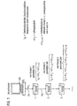
- the communication system of FIG. 1 includes a clock master 100, which is used to synchronize the local time bases in the nodes 1, 2, 3, ... of the communication system is used.
- a clock master 100 which is used to synchronize the local time bases in the nodes 1, 2, 3, ... of the communication system is used.
- an automation system it may be at the Nodes 1, 2, 3, ... to sensors, actuators, drives or other components or sub-systems act.
- the time master 100 sends a synchronization telegram to the node 1 at the time of transmission t 0.
- the synchronization telegram contains the desired reception time at the node 1 as user data resulting from the addition of the transmission time t 0 and the line delay ⁇ t L between the time master 100 and the node 1 via the line 101 results.
- a deviation between the desired reception time and the actual reception time determined on the basis of the local time base of the node 1 is used to readjust the local time base of the node 1.
- the node 1 After receiving the synchronization telegram from the time master 100, the node 1 generates another synchronization telegram for the node 2. This is sent via the line 102 from the node 1 to the node 2.
- the synchronization telegram sent from the node 1 to the node 2 contains the desired reception time t 0 + ⁇ t L , which the node 1 has received from the clock master 100 plus a time period ⁇ t 1 ⁇ 2 , the time ⁇ t 1 ⁇ 2 the Residence time in the network node 1 plus the line transit time over the line 102.
- the residence time is the period between the reception of the synchronization telegram from the clock master 100 at node 1 and resending the synchronization telegram from node 1 to node 2.
- This residence time can be very accurate due to the local time base of the node 1, even if they are not exact synchronized, since it is not the absolute time, but only on the period, ie on the relative residence time in the node, in particular node 1, arrives.
- the readjustment of the time base in the node 2 due to received by the node 1 synchronization telegram takes place basically the same as the previous readjustment of Time base in the node 1.
- a basis for the readjustment in the node 2 is thus a possible deviation between which, based on the local time base of the node 2 determined Actual reception time and the target reception time used, wherein the target reception time in the payload of the includes received from the node 1 synchronization telegram is.
- the node 2 adds to this target reception time, that is, at the time t 0 + .DELTA.t L + .DELTA.t 1 ⁇ 2 , the time .DELTA.t 2 ⁇ 3 to generate another synchronization telegram for the subsequent node 3, etc.
- FIG. 2 shows a block diagram corresponding to FIG.
- the time master 100 has a master time base 103 and a memory 104 for storing the line delay ⁇ t L via the line 101. Furthermore, the time master 100 has a program 105 which serves for the cyclical generation and transmission of synchronization telegrams 106. In each case, these synchronization telegrams contain the respective transmission time t 0 plus the line delay ⁇ t L as user data.
- the node 1 has a local time base 107 with a regulation 108. Further, the node 1 has a memory 109 for storage the reception times of synchronization telegrams 106. Preferably, the memory 109 also serves for storage the reception times of others received from the node 1 Data telegrams.
- the node 1 further has a memory 110 for storage the desired reception time, which by means of a synchronization telegram 106 has been received.
- the node 1 further has a memory 111, which is for fixing of transmission times of data telegrams and in particular synonymous of synchronization telegrams 114 to the adjacent Node 2 is used.
- the runtime of the node 1 to node 2 via line 102 is in memory 112 filed.
- the node 1 has a program 113 which is for generation and transmission of synchronization telegrams 114 to the Node 2 is used.
- the synchronization telegrams contain 114 each of the target reception time from the Memory 110 plus the residence time plus the runtime from the memory 112. The residence time results thereby from the difference of the transmission time of the concerning Synchronization telegram 114 and the reception time of the preceding synchronization telegram 106.
- the node 2 and other nodes not shown in FIG of the communication system are basically the same structure like the node 1.
- the clock master During operation of the communication system, the clock master generates a synchronization telegram 106, which is sent from the node 1 is received.
- the actual reception time is in the Memory 109 stored; the target reception time will be off the synchronization telegram 106 read and in the memory 110 filed.
- the Time base 107 Based on a deviation between the actual reception time and the target reception time becomes the Time base 107 readjusted by the controller 108. Through this Readjustment is a match of the time base 107 with the master time base 103 in a narrow tolerance range guaranteed.
- the program 113 then generates the synchronization telegram 114, which as payload the target reception time of Synchronization telegram 114 at the node 2 includes. Due to this, the time base of node 2 is also readjusted.
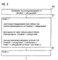
- FIG. 3 shows a corresponding flowchart.
- Step 300 sends the clock master a synchronization telegram with the setpoint reception time of the synchronization telegram at an adjacent node 1 as payload.
- step 301 node 1 receives this synchronization message and determines for this synchronization telegram the reception time based on the local time base. This reception time becomes the actual reception time designated. The actual reception time and the target reception time are stored by the node 1. A Deviation between the actual and desired reception times is used as the basis for determining a manipulated variable Readjustment of the local time base used in node 1, to synchronize to the master time base of the time master bring.
- FIG. 4 shows the determination of the line delay ⁇ t L via the line 102 between the nodes 1 and 2.
- the node 1 sends to the node 2 a transit time measurement request telegram.
- the transmission time t Send-Req the receiver, ie the node 2 stores the reception time t Rec-Req of the time-of-flight measurement call-up telegram at the node 2 in the data field of the time-of-flight measurement call-up telegram and sends a time-of-flight measurement response telegram at the time t Send-resp back to node 1.
- the line transit time ⁇ t L is determined based on the total time required to perform the transit time measurement minus the dwell time in the node 2.
- the run time for the outward and return journey is assumed to be the same in the calculation, ie the return line must be the same length.
- This process can be initiated, for example, on the basis of the program 113 in the node 1 (see FIG. The so determined line running time .DELTA.t L is then entered by the program 113 in the memory 112.
Landscapes
- Engineering & Computer Science (AREA)
- Theoretical Computer Science (AREA)
- Computer Networks & Wireless Communication (AREA)
- Signal Processing (AREA)
- Physics & Mathematics (AREA)
- General Engineering & Computer Science (AREA)
- General Physics & Mathematics (AREA)
- Synchronisation In Digital Transmission Systems (AREA)
- Computer And Data Communications (AREA)
- Data Exchanges In Wide-Area Networks (AREA)
- Mobile Radio Communication Systems (AREA)
Description
- sowohl für eine Analyse des Telegrammverkehrs im Netzwerk,
- als auch für synchronisierte Aktionen in verteilten Systemen der Automatisierungstechnik.
- dem Sendezeitpunkt des Synchronisationstelegramms und
- der Leitungslaufzeit zum benachbarten Netzwerk-Knoten, der das Telegramm empfängt ein.
- der lokalen Aufenthaltszeit := (Weiterleitungszeitpunkt-Empfangszeitpunkt) in diesem Knoten und
- der Leitungslaufzeit zum benachbarten Netzwerk-Knoten, der das Telegramm empfängt.
- Der Initiator der Laufzeitmessung trägt ins Datenfeld des Laufzeitmessungs-Aufruftelegramms den Sendezeitpunkt tSend-Req ein.
- Der Empfänger dieses Laufzeitmessungs-Aufruftelegramms
speichert den Empfangszeitpunkt
tRec-Req ab und schickt ein Laufzeitmessungs-Antworttelegramm
zum Zeitpunkt tSend-Resp zurück.
Im Datenfeld dieses Antworttelegramms sind folgende Zeiten eingetragen: - der Sendezeitpunkt tSend-Req des Aufruftelegramms vom Initiator der Laufzeitmessung
- die Verzögerungszeit (tSend-Resp - tRec-Req) zwischen Aufrufund Antworttelegramm.
- Der Initiator der Laufzeitmessung speichert den Ankunftszeitpunkt des Laufzeitmessungs-Antworttelegramms tRec-Resp ab und bestimmt die Leitungslaufzeit mit Hilfe der Formel:
-
- Ein Uhrzeitmaster sendet periodisch mindestens zwei Synchronisationstelegramme auf unterschiedlichen Wegen zu den Netzwerk-Knoten. Die Regelungssoftware der Netzwerk-Knoten muss jeweils alle empfangenen Synchronisationstelegramme bei der Uhrzeitsynchronisation berücksichtigen.
- Der aktive Uhrzeitmaster und ein redundanter Uhrzeitmaster senden gleichzeitig periodisch Synchronisationstelegramme. Ausgewertet und zur Regelung der Uhrzeit verwendet werden jedoch nur die Synchronisationstelegramme des aktiven Uhrzeitmasters. Erst wenn der redundante Uhrzeitmaster aufgrund ausbleibender Synchronisationstelegramme vom bisher aktiven Uhrzeitmaster seine Synchronisationstelegramme als aktiv markiert, werden diese von der Regelungssoftware zur Uhrzeitsynchronisierung verwendet.
- dem Sendezeitpunkt und
- der Leitungslaufzeit zum benachbarten Netzwerk-Knoten, der das Telegramm empfängt, ein.
- der Aufenthaltszeit im Netzwerk-Knoten := (Weiterleitungszeitpunkt - Empfangszeitpunkt) und
- der Leitungslaufzeit zum benachbarten Netzwerk-Knoten, der das Telegramm empfängt.
- wird das Standard-Uhrzeittelegramm wieder "entpackt" und
- die eingetragene Standard-Uhrzeit um die Telegrammlaufzeit im Netzwerk korrigiert.
- Figur 1
- eine Prinzipdarstellung für die Synchronisation der Knoten eines Kommunikationssystems basierend auf einem Uhrzeitmaster,
- Figur 2
- ein Blockdiagramm eines Uhrzeitmasters und eines Knotens,
- Figur 3
- ein Flussdiagramm für die Synchronisation der lokalen Zeitbasen,
- Figur 4
- eine Prinzipdarstellung der Ermittlung der Leitungslaufzeit zwischen benachbarten Netzwerkknoten.
- der Sendezeitpunkt tSend-Req des Aufruftelegramms vom Initiator der Laufzeitmessung
- die Verzögerungszeit (tSend-Resp - tRec-Req) zwischen Aufrufund Antworttelegramm.
- Der Knoten 1 der Laufzeitmessung speichert den Ankunftszeitpunkt des Laufzeitmessungs-Antworttelegramms tRec-Resp ab und bestimmt die Leitungslaufzeit mit Hilfe der Formel:
-
- 1
- Knoten
- 2
- Knoten
- 3
- Knoten
- 100
- Uhrzeitmaster
- 101
- Leitung
- 102
- Leitung
- 103
- Master Zeitbasis
- 104
- Speicher
- 105
- Programm
- 106
- Synchronisationstelegramm
- 107
- lokale Zeitbasis
- 108
- Regelung
- 109
- Speicher
- 110
- Speicher
- 111
- Speicher
- 112
- Speicher
- 113
- Programm
- 114
- Synchronisationstelegramm
Claims (7)
- Verfahren zur Synchronisation von Knoten (1, 2, 3) eines Kommunikationssystems mit folgenden Schritten:Empfang eines ersten Synchronisationstelegramms (106) durch einen ersten Knoten (1), wobei das erste Synchronisationstelegramm einen ersten Soll-Empfangszeitpunkt (t0 + Δt2) an dem ersten Knoten beinhaltet,Nachregelung einer Zeitbasis (107) des ersten Knotens basierend auf einer Abweichung zwischen einem, aufgrund der Zeitbasis ermittelten Ist-Empfangszeitpunkt und dem ersten Soll-Empfangszeitpunkt,Sendung eines zweiten Synchronisationstelegramms (114) von dem ersten Knoten an einen benachbarten zweiten Knoten (2), wobei das zweite Synchronisationstelegramm einen zweiten Soll-Empfangszeitpunkt (t0 + ΔtL + Δt1→2) an dem zweiten Knoten beinhaltet,
dadurch gekennzeichnet, daß der zweite Soll-Empfangszeitpunkt an dem zweiten Knoten ermittelt wird durch:Bestimmung einer Aufenthaltszeit aus dem Sendezeitpunkt des zweiten Synchronisationstelegramms und dem Empfangszeitpunkt des ersten Synchronisationstelegramms,Addition der Aufenthaltszeit und einer Leitungslaufzeit (Δt1→2) zwischen dem ersten Knoten und dem zweiten Knoten zu dem ersten Soll-Empfangszeitpunkt an dem ersten Knoten, um den zweiten Soll-Empfangszeitpunkt zu bestimmen. - Verfahren nach Anspruch 1, wobei das erste Synchronisationstelegramm durch einen Uhrzeitmaster (100) mit einer Master-Zeitbasis (103) erzeugt wird, wobei der Soll-Empfangszeitpunkt an dem ersten Knoten aus der, aufgrund der Master-Zeitbasis ermittelten Sendezeit und der Leitungslaufzeit (104) von dem Uhrzeitmaster an den ersten Knoten bestimmt wird.
- Digitales Speichermedium, insbesondere Diskette, CD-ROM oder Halbleiterspeicher, mit Programmmitteln zur Nachregelung der Zeitbasis (107) eines ersten Knotens (1) eines Kommunikationssystems aufgrund des Empfangs eines ersten Synchronisationstelegramms (106) durch den ersten Knoten (1), wobei das Synchronisationstelegramm einen ersten Soll-Empfangszeitpunkt (t0 + ΔtL) an dem ersten Knoten beinhaltet, wobei die Nachregelung der Zeitbasis des ersten Knotens basierend auf einer Abweichung zwischen dem, aufgrund der Zeitbasis ermittelten Ist-Empfangszeitpunkt des ersten Synchronisationstelegramms und dem Soll-Empfangszeitpunkt an dem ersten Knoten erfolgt und wobei die Programmmittel zur Erzeugung eines zweiten Synchronisationstelegramms (114) für einen zweiten Knoten ausgebildet sind, und das zweite Synchronisationstelegramm einen zweiten Soll-Empfangszeitpunkt (t0 + ΔtL + Δt1→2) an dem zweiten Knoten beinhaltet,
dadurch gekennzeichnet, daß der zweite Soll-Empfangszeitpunkt an dem zweiten Knoten wie folgt ermittelt wird:Bestimmung einer Aufenthaltszeit in dem ersten Knoten aus dem Sendezeitpunkt des zweiten Synchronisationstelegramms und dem Empfangszeitpunkt des ersten Synchronisationstelegramms,Addition einer Leitungslaufzeit (Δt1→2) zwischen dem ersten und dem zweiten Knoten zu dem ersten Soll-Empfangszeitpunkt an dem ersten Knoten, um den zweiten Soll-Empfangszeitpunkt zu bestimmen. - Digitales Speichermedium nach Anspruch 3, wobei die Programmmittel zur Bestimmung der Leitungslaufzeit zwischen dem ersten und dem zweiten Knoten ausgebildet sind.
- Knoten (1) für ein isochrones Kommunikationssystem, mit einer Zeitbasis (107) und mit Regelungsmitteln (108) zur Regelung der Zeitbasis (107), wobei die Regelungsmittel so ausgebildet sind, dass die Regelung der Zeitbasis basierend auf einer Abweichung zwischen dem, aufgrund der Zeitbasis ermittelten Ist-Empfangszeitpunkt eines ersten Synchronisationstelegramms (106) und dem in dem Synchronisationstelegramm beinhalteten ersten Soll-Empfangszeitpunkt (t0 + ΔtL) an dem Knoten durchgeführt wird, mit Mitteln zur Erzeugung eines zweiten Synchronisationstelegramms (114) für einen anderen Knoten (2), wobei das zweite Synchronisationstelegramm einen zweiten Soll-Empfangszeitpunkt (t0 + ΔtL + Δt1→2) an dem anderen Knoten beinhaltet,
dadurch gekennzeichnet, daß der zweite Soll-Empfangszeitpunkt an dem anderen Knoten wie folgt ermittelbar ist:Bestimmung einer Aufenthaltszeit aus der Differenz der Sendezeit des zweiten Synchronisationstelegramms und dem Empfangszeitpunkt des ersten Synchronisationstelegramms,Addition der Leitungslaufzeit (Δt1→2) zwischen dem Knoten und dem anderen Knoten zu dem ersten Soll-Empfangszeitpunkt an dem Knoten, um den zweiten Soll-Empfangszeitpunkt zu bestimmen. - Knoten nach Anspruch 5 mit Mitteln zur Bestimmung der Leitungslaufzeit zwischen dem Knoten und dem benachbarten anderen Knoten.
- Kommunikationssystem mit mindestens einem Uhrzeitmaster mit einer Masterzeitbasis (103) und mit Mitteln zur Sendung eines ersten Synchronisationstelegramms (106) an einen benachbarten ersten Knoten (1) des Kommunikationssystems, wobei das erste Synchronisationstelegramm einen Soll-Empfangszeitpunkt an dem ersten Knoten beinhaltet, der aus dem Sendezeitpunkt des ersten Synchronisationstelegramms von dem Uhrzeitmaster und der Leitungslaufzeit (104) zwischen dem Uhrzeitmaster und dem ersten Knoten ermittelt wird, und mit mehreren Knoten (2, 3) nach einem der vorhergehenden Ansprüche 5 oder 6.
Applications Claiming Priority (5)
| Application Number | Priority Date | Filing Date | Title |
|---|---|---|---|
| DE10147433 | 2001-09-26 | ||
| DE10147433 | 2001-09-26 | ||
| DE10229110A DE10229110A1 (de) | 2001-09-26 | 2002-06-28 | Verfahren zur Synchronisation von Knoten eines Kommunikationssystems |
| DE10229110 | 2002-06-28 | ||
| PCT/DE2002/003432 WO2003028258A1 (de) | 2001-09-26 | 2002-09-20 | Verfahren zur synchronisation von knoten eines kommunikationssystems |
Publications (2)
| Publication Number | Publication Date |
|---|---|
| EP1430627A1 EP1430627A1 (de) | 2004-06-23 |
| EP1430627B1 true EP1430627B1 (de) | 2005-02-09 |
Family
ID=26010228
Family Applications (1)
| Application Number | Title | Priority Date | Filing Date |
|---|---|---|---|
| EP02774353A Expired - Lifetime EP1430627B1 (de) | 2001-09-26 | 2002-09-20 | Verfahren zur synchronisation von knoten eines kommunikationssystems |
Country Status (5)
| Country | Link |
|---|---|
| US (1) | US7366205B2 (de) |
| EP (1) | EP1430627B1 (de) |
| AT (1) | ATE289137T1 (de) |
| ES (1) | ES2236585T3 (de) |
| WO (1) | WO2003028258A1 (de) |
Cited By (1)
| Publication number | Priority date | Publication date | Assignee | Title |
|---|---|---|---|---|
| US9756153B2 (en) | 2011-06-01 | 2017-09-05 | Finite State Research Llc | Method for improving accuracy in computation of one-way transfer time for network time synchronization |
Families Citing this family (37)
| Publication number | Priority date | Publication date | Assignee | Title |
|---|---|---|---|---|
| US6598074B1 (en) * | 1999-09-23 | 2003-07-22 | Rocket Network, Inc. | System and method for enabling multimedia production collaboration over a network |
| US7570669B2 (en) * | 2003-08-08 | 2009-08-04 | Opnet Technologies, Inc. | Synchronizing packet traces |
| US7649835B2 (en) * | 2003-11-19 | 2010-01-19 | Honeywell International Inc. | Unsynchronous mode brother's keeper bus guardian for a ring networks |
| DE102004012506B4 (de) * | 2004-03-15 | 2006-08-10 | Siemens Ag | Verfahren zur Erfassung von Signalen in einer zentralen Erfassungseinheit |
| US8930579B2 (en) * | 2004-09-13 | 2015-01-06 | Keysight Technologies, Inc. | System and method for synchronizing operations of a plurality of devices via messages over a communication network |
| US7768931B2 (en) * | 2004-10-07 | 2010-08-03 | Westerngeco L.L.C. | Hardware-based network packet timestamps: improved network clock synchronization |
| DE102004050423A1 (de) * | 2004-10-15 | 2006-04-20 | Bosch Rexroth Ag | Kommunikationssystem und Verfahren zur Synchronisation desselben |
| US7904184B2 (en) * | 2004-11-23 | 2011-03-08 | Rockwell Automation Technologies, Inc. | Motion control timing models |
| US7983769B2 (en) * | 2004-11-23 | 2011-07-19 | Rockwell Automation Technologies, Inc. | Time stamped motion control network protocol that enables balanced single cycle timing and utilization of dynamic data structures |
| US7649912B2 (en) | 2005-04-27 | 2010-01-19 | Rockwell Automation Technologies, Inc. | Time synchronization, deterministic data delivery and redundancy for cascaded nodes on full duplex ethernet networks |
| ES2387100T3 (es) * | 2005-07-28 | 2012-09-13 | Ima Industria Macchine Automatiche S.P.A. | Método de intercambio de información entre unidades digitales en un sistema distribuido |
| DE102006010748A1 (de) * | 2006-03-08 | 2007-09-13 | Pepperl + Fuchs Gmbh | Verfahren zum Aufzeichnen von Eingangssignaländerungen |
| US7689854B2 (en) * | 2006-09-22 | 2010-03-30 | Agilent Technologies, Inc. | Method and apparatus for establishing IEEE 1588 clock synchronization across a network element comprising first and second cooperating smart interface converters wrapping the network element |
| US7668084B2 (en) * | 2006-09-29 | 2010-02-23 | Honeywell International Inc. | Systems and methods for fault-tolerant high integrity data propagation using a half-duplex braided ring network |
| US7889683B2 (en) * | 2006-11-03 | 2011-02-15 | Honeywell International Inc. | Non-destructive media access resolution for asynchronous traffic in a half-duplex braided-ring |
| US7656881B2 (en) * | 2006-12-13 | 2010-02-02 | Honeywell International Inc. | Methods for expedited start-up and clique aggregation using self-checking node pairs on a ring network |
| US7912094B2 (en) * | 2006-12-13 | 2011-03-22 | Honeywell International Inc. | Self-checking pair-based master/follower clock synchronization |
| CN101578806B (zh) | 2007-03-28 | 2013-02-13 | 株式会社安川电机 | 通信装置、同步通信系统及同步通信方法 |
| US8838776B2 (en) * | 2007-09-26 | 2014-09-16 | Vega Grieshaber Kg | Method for the automatic time synchronisation of devices in network-based systems |
| US7778159B2 (en) * | 2007-09-27 | 2010-08-17 | Honeywell International Inc. | High-integrity self-test in a network having a braided-ring topology |
| US20100049717A1 (en) * | 2008-08-20 | 2010-02-25 | Ryan Michael F | Method and systems for sychronization of process control servers |
| DE102009032229B4 (de) * | 2009-07-08 | 2012-06-14 | Abb Technology Ag | Verfahren und Einrichtung zur Protokollierung von Prozessvariablen eines digitalen Feldgerätes |
| AT509700B1 (de) * | 2010-04-07 | 2019-05-15 | Tttech Computertechnik Ag | Verfahren und apparat zur fehlertoleranten zeitgesteuerten echtzeitkommunikation |
| US8670466B1 (en) * | 2010-12-22 | 2014-03-11 | Applied Micro Circuits Corporation | System and method for residence time calculation |
| EP2506470B1 (de) | 2011-03-29 | 2013-05-29 | Alcatel Lucent | Verfahren, Vorrichtung und System zur Zeitverteilung in einem Telekommunikationsnetzwerk |
| EP2527935B1 (de) * | 2011-05-26 | 2014-12-03 | Siemens Aktiengesellschaft | Verfahren zum Betrieb eines Automatisierungssystems |
| US9363304B2 (en) * | 2012-06-06 | 2016-06-07 | Google Inc. | Synchronizing action execution across networked nodes using relative time |
| DK2709298T3 (en) | 2012-09-18 | 2018-08-27 | Omicron Electronics Gmbh | Synchronization method and electronic device using redundant connections |
| US9759703B2 (en) | 2013-09-27 | 2017-09-12 | Li-Cor, Inc. | Systems and methods for measuring gas flux |
| CN103684735A (zh) * | 2013-11-12 | 2014-03-26 | 航天科工深圳(集团)有限公司 | 一种分布式装置的同步方法 |
| DE102014215737B3 (de) * | 2014-08-08 | 2015-07-16 | Karl Christoph Ruland | Verifizierung von Zeitzeichen |
| US10165530B2 (en) | 2016-03-22 | 2018-12-25 | Christoph RULAND | Verification of time information transmitted by time signals or time telegrams |
| US10158441B1 (en) * | 2017-06-02 | 2018-12-18 | Apple Inc. | Securing time between nodes |
| DE102018112357A1 (de) * | 2018-05-23 | 2019-11-28 | Beckhoff Automation Gmbh | Datenübertragungsverfahren und Automatisierungskommunikationsnetzwerk |
| US10848160B2 (en) | 2018-07-10 | 2020-11-24 | Aerotech, Inc. | Devices, systems, and methods for reducing jitter in control systems |
| US10809760B1 (en) * | 2018-10-29 | 2020-10-20 | Facebook, Inc. | Headset clock synchronization |
| EP3873009B1 (de) * | 2020-02-28 | 2024-08-21 | Siemens Aktiengesellschaft | Verfahren zur synchronisation von steuerungsanwendungen über ein kommunikationsnetz zur übermittlung zeitkritischer daten, netzinfrastrukturgerät und kommunikationsendgerät |
Family Cites Families (15)
| Publication number | Priority date | Publication date | Assignee | Title |
|---|---|---|---|---|
| US4982185A (en) * | 1989-05-17 | 1991-01-01 | Blh Electronics, Inc. | System for synchronous measurement in a digital computer network |
| US5333299A (en) * | 1991-12-31 | 1994-07-26 | International Business Machines Corporation | Synchronization techniques for multimedia data streams |
| DE4215380A1 (de) | 1992-05-11 | 1993-11-18 | Siemens Ag | Verfahren zum Synchronisieren von lokalen Zeitgebern eines Automatisierungssystems |
| US5537549A (en) * | 1993-04-28 | 1996-07-16 | Allen-Bradley Company, Inc. | Communication network with time coordinated station activity by time slot and periodic interval number |
| US5408506A (en) | 1993-07-09 | 1995-04-18 | Apple Computer, Inc. | Distributed time synchronization system and method |
| US5566180A (en) * | 1994-12-21 | 1996-10-15 | Hewlett-Packard Company | Method for recognizing events and synchronizing clocks |
| US5828670A (en) * | 1995-06-06 | 1998-10-27 | Symmetricom, Inc. | Distribution of synchronization in a synchronous optical environment |
| JPH1013394A (ja) * | 1996-06-21 | 1998-01-16 | Fanuc Ltd | 通信における同期方法 |
| JPH10210108A (ja) | 1996-11-20 | 1998-08-07 | Okuma Mach Works Ltd | 通信制御方法及び装置 |
| DE19703963A1 (de) | 1997-02-03 | 1998-08-06 | Siemens Ag | Verfahren und Vorrichtung zum Austauschen von Daten zwischen dezentral anordbaren elektronischen Baugruppen |
| US6665316B1 (en) * | 1998-09-29 | 2003-12-16 | Agilent Technologies, Inc. | Organization of time synchronization in a distributed system |
| DE19917354B4 (de) | 1999-04-16 | 2005-12-22 | Siemens Ag | Synchronisationsverfahren für eine Haupteinheit und mindestens eine Nebeneiheit mit internen, miteinander zu synchronisierenden Zeitgebern, hiermit korrespodierndes Kommunikationssystem sowie Haupteinheit und Nebeneinheit eines derartigen Kommunikationssystems |
| DE19943779A1 (de) | 1999-09-13 | 2001-03-22 | Siemens Ag | Anordnung zum Synchronisieren von über ein Kommunikationsnetz gekoppelten Kommunikationssystemkomponenten |
| GB9930132D0 (en) * | 1999-12-22 | 2000-02-09 | Ericsson Telefon Ab L M | Telecommunication network synchronisation |
| US6914914B1 (en) * | 2001-05-22 | 2005-07-05 | Rockwell Automation Technologies, Inc. | System and method for multi-chassis configurable time synchronization |
-
2002
- 2002-09-20 EP EP02774353A patent/EP1430627B1/de not_active Expired - Lifetime
- 2002-09-20 ES ES02774353T patent/ES2236585T3/es not_active Expired - Lifetime
- 2002-09-20 AT AT02774353T patent/ATE289137T1/de not_active IP Right Cessation
- 2002-09-20 WO PCT/DE2002/003432 patent/WO2003028258A1/de not_active Ceased
- 2002-09-20 US US10/490,525 patent/US7366205B2/en not_active Expired - Fee Related
Cited By (1)
| Publication number | Priority date | Publication date | Assignee | Title |
|---|---|---|---|---|
| US9756153B2 (en) | 2011-06-01 | 2017-09-05 | Finite State Research Llc | Method for improving accuracy in computation of one-way transfer time for network time synchronization |
Also Published As
| Publication number | Publication date |
|---|---|
| ATE289137T1 (de) | 2005-02-15 |
| ES2236585T3 (es) | 2005-07-16 |
| WO2003028258A1 (de) | 2003-04-03 |
| EP1430627A1 (de) | 2004-06-23 |
| US20040258097A1 (en) | 2004-12-23 |
| US7366205B2 (en) | 2008-04-29 |
Similar Documents
| Publication | Publication Date | Title |
|---|---|---|
| WO2003028258A1 (de) | Verfahren zur synchronisation von knoten eines kommunikationssystems | |
| DE10113261C2 (de) | Synchrones, getaktetes Kommunikationssystem mit dezentralen Ein-/Ausgabe-Baugruppen und Verfahren zur Einbindung dezentraler Ein-/Ausgabe-Baugruppen in ein solches System | |
| EP1368942B1 (de) | Verfahren und system zur kopplung von datennetzen | |
| EP1659718B1 (de) | Synchronisatonsverfahren und Steuerungssystem für die Synchronisation von Nebeneinheiten, sowie synchronisierbare Nebeneinheiten | |
| EP1368728B1 (de) | Synchrones, getaktetes kommunikationssystem mit relativuhr und verfahren zum aufbau eines solchen systems | |
| EP3814856B1 (de) | Echtzeit-automatisierungseinrichtung mit einem echtzeit-datenbus | |
| EP1648117B1 (de) | Verfahren zur Synchronisation in einem redundanten Kommunikationssystem | |
| EP1639758B1 (de) | Verfahren und vorrichtung zum austausch von daten über ein bussystem | |
| EP1826646B1 (de) | Verfahren, Knoten und Netzwerk zum zyklischen Versenden von Ethernet-Telegrammen | |
| EP3864780B1 (de) | Verfahren zum betreiben eines netzwerkteilnehmers in einem automatisierungskommunikationsnetzwerk | |
| DE10229110A1 (de) | Verfahren zur Synchronisation von Knoten eines Kommunikationssystems | |
| EP1435027B1 (de) | Verfahren zur übertragung eines datentelegramms zwischen einer echtzeit-domain und einer nicht-echtzeit-domain und koppeleinheit | |
| EP1436924B1 (de) | Verfahren zum betrieb eines endteilnehmers eines isochronen, zyklischen kommunikationssystems | |
| EP1484679B1 (de) | Sicherstellung von maximalen Reaktionszeiten in komplexen oder verteilten sicheren und/oder nicht sicheren Systemen | |
| DE10140861A1 (de) | Verfahren und System zur Kopplung von Datennetzen | |
| WO2025103867A1 (de) | Verfahren zum bestimmen einer busteilnehmeranordnung in einem automatisierungsnetzwerk und automatisierungsnetzwerk | |
| EP3632055B1 (de) | Übertragen von daten auf einem lokalbus | |
| DE19504291C2 (de) | Verfahren zum Betreiben eines Netzwerks | |
| DE102017012250B4 (de) | Übertragen von Daten auf einem Lokalbus | |
| DE102017108578B4 (de) | Steuern eines Automatisierungsprozesses über ein Datennetzwerk | |
| EP1430657A1 (de) | Verfahren zur erstellung einer dynamischen adresstabelle für einen koppelknoten in einem datennetz und verfahren zur übertragung eines datentelegramms | |
| WO2025210230A1 (de) | Computerimplementiertes verfahren für eine co-simulation | |
| DE10147429A1 (de) | System und Verfahren zur Planung des Datenverkehrs in Kommunikationssystemen, insbesondere Real-time Ethernet | |
| DE102012021888A1 (de) | Kommunikationsverfahren für verteilte sicherheitsgerichtete Automatisierungseinrichtungen | |
| DE4304995A1 (de) | Empfängerschaltung für eine Teilnehmerstation eines Netzwerks |
Legal Events
| Date | Code | Title | Description |
|---|---|---|---|
| PUAI | Public reference made under article 153(3) epc to a published international application that has entered the european phase |
Free format text: ORIGINAL CODE: 0009012 |
|
| 17P | Request for examination filed |
Effective date: 20040303 |
|
| AK | Designated contracting states |
Kind code of ref document: A1 Designated state(s): AT BE BG CH CY CZ DE DK EE ES FI FR GB GR IE IT LI LU MC NL PT SE SK TR |
|
| GRAP | Despatch of communication of intention to grant a patent |
Free format text: ORIGINAL CODE: EPIDOSNIGR1 |
|
| GRAS | Grant fee paid |
Free format text: ORIGINAL CODE: EPIDOSNIGR3 |
|
| GRAA | (expected) grant |
Free format text: ORIGINAL CODE: 0009210 |
|
| AK | Designated contracting states |
Kind code of ref document: B1 Designated state(s): AT BE BG CH CY CZ DE DK EE ES FI FR GB GR IE IT LI LU MC NL PT SE SK TR |
|
| PG25 | Lapsed in a contracting state [announced via postgrant information from national office to epo] |
Ref country code: SK Free format text: LAPSE BECAUSE OF FAILURE TO SUBMIT A TRANSLATION OF THE DESCRIPTION OR TO PAY THE FEE WITHIN THE PRESCRIBED TIME-LIMIT Effective date: 20050209 Ref country code: CZ Free format text: LAPSE BECAUSE OF FAILURE TO SUBMIT A TRANSLATION OF THE DESCRIPTION OR TO PAY THE FEE WITHIN THE PRESCRIBED TIME-LIMIT Effective date: 20050209 Ref country code: EE Free format text: LAPSE BECAUSE OF FAILURE TO SUBMIT A TRANSLATION OF THE DESCRIPTION OR TO PAY THE FEE WITHIN THE PRESCRIBED TIME-LIMIT Effective date: 20050209 Ref country code: BG Free format text: LAPSE BECAUSE OF FAILURE TO SUBMIT A TRANSLATION OF THE DESCRIPTION OR TO PAY THE FEE WITHIN THE PRESCRIBED TIME-LIMIT Effective date: 20050209 Ref country code: FI Free format text: LAPSE BECAUSE OF FAILURE TO SUBMIT A TRANSLATION OF THE DESCRIPTION OR TO PAY THE FEE WITHIN THE PRESCRIBED TIME-LIMIT Effective date: 20050209 Ref country code: IE Free format text: LAPSE BECAUSE OF FAILURE TO SUBMIT A TRANSLATION OF THE DESCRIPTION OR TO PAY THE FEE WITHIN THE PRESCRIBED TIME-LIMIT Effective date: 20050209 Ref country code: TR Free format text: LAPSE BECAUSE OF FAILURE TO SUBMIT A TRANSLATION OF THE DESCRIPTION OR TO PAY THE FEE WITHIN THE PRESCRIBED TIME-LIMIT Effective date: 20050209 |
|
| REG | Reference to a national code |
Ref country code: GB Ref legal event code: FG4D Free format text: NOT ENGLISH |
|
| REG | Reference to a national code |
Ref country code: CH Ref legal event code: EP Ref country code: CH Ref legal event code: NV Representative=s name: SIEMENS SCHWEIZ AG |
|
| REG | Reference to a national code |
Ref country code: IE Ref legal event code: FG4D Free format text: GERMAN |
|
| REF | Corresponds to: |
Ref document number: 50202249 Country of ref document: DE Date of ref document: 20050317 Kind code of ref document: P |
|
| GBT | Gb: translation of ep patent filed (gb section 77(6)(a)/1977) |
Effective date: 20050319 |
|
| PG25 | Lapsed in a contracting state [announced via postgrant information from national office to epo] |
Ref country code: GR Free format text: LAPSE BECAUSE OF FAILURE TO SUBMIT A TRANSLATION OF THE DESCRIPTION OR TO PAY THE FEE WITHIN THE PRESCRIBED TIME-LIMIT Effective date: 20050509 Ref country code: DK Free format text: LAPSE BECAUSE OF FAILURE TO SUBMIT A TRANSLATION OF THE DESCRIPTION OR TO PAY THE FEE WITHIN THE PRESCRIBED TIME-LIMIT Effective date: 20050509 Ref country code: SE Free format text: LAPSE BECAUSE OF FAILURE TO SUBMIT A TRANSLATION OF THE DESCRIPTION OR TO PAY THE FEE WITHIN THE PRESCRIBED TIME-LIMIT Effective date: 20050509 |
|
| REG | Reference to a national code |
Ref country code: ES Ref legal event code: FG2A Ref document number: 2236585 Country of ref document: ES Kind code of ref document: T3 |
|
| PG25 | Lapsed in a contracting state [announced via postgrant information from national office to epo] |
Ref country code: CY Free format text: LAPSE BECAUSE OF FAILURE TO SUBMIT A TRANSLATION OF THE DESCRIPTION OR TO PAY THE FEE WITHIN THE PRESCRIBED TIME-LIMIT Effective date: 20050920 |
|
| REG | Reference to a national code |
Ref country code: IE Ref legal event code: FD4D |
|
| PG25 | Lapsed in a contracting state [announced via postgrant information from national office to epo] |
Ref country code: LU Free format text: LAPSE BECAUSE OF NON-PAYMENT OF DUE FEES Effective date: 20050930 Ref country code: MC Free format text: LAPSE BECAUSE OF NON-PAYMENT OF DUE FEES Effective date: 20050930 |
|
| PLBE | No opposition filed within time limit |
Free format text: ORIGINAL CODE: 0009261 |
|
| STAA | Information on the status of an ep patent application or granted ep patent |
Free format text: STATUS: NO OPPOSITION FILED WITHIN TIME LIMIT |
|
| ET | Fr: translation filed | ||
| 26N | No opposition filed |
Effective date: 20051110 |
|
| PG25 | Lapsed in a contracting state [announced via postgrant information from national office to epo] |
Ref country code: PT Free format text: LAPSE BECAUSE OF NON-PAYMENT OF DUE FEES Effective date: 20050709 |
|
| PGFP | Annual fee paid to national office [announced via postgrant information from national office to epo] |
Ref country code: AT Payment date: 20080808 Year of fee payment: 7 Ref country code: NL Payment date: 20080910 Year of fee payment: 7 |
|
| PGFP | Annual fee paid to national office [announced via postgrant information from national office to epo] |
Ref country code: CH Payment date: 20081211 Year of fee payment: 7 |
|
| PGFP | Annual fee paid to national office [announced via postgrant information from national office to epo] |
Ref country code: BE Payment date: 20080915 Year of fee payment: 7 Ref country code: ES Payment date: 20081020 Year of fee payment: 7 |
|
| REG | Reference to a national code |
Ref country code: CH Ref legal event code: PCAR Free format text: SIEMENS SCHWEIZ AG;INTELLECTUAL PROPERTY FREILAGERSTRASSE 40;8047 ZUERICH (CH) |
|
| BERE | Be: lapsed |
Owner name: *SIEMENS A.G. Effective date: 20090930 |
|
| REG | Reference to a national code |
Ref country code: NL Ref legal event code: V1 Effective date: 20100401 |
|
| REG | Reference to a national code |
Ref country code: CH Ref legal event code: PL |
|
| PG25 | Lapsed in a contracting state [announced via postgrant information from national office to epo] |
Ref country code: AT Free format text: LAPSE BECAUSE OF NON-PAYMENT OF DUE FEES Effective date: 20090920 |
|
| PG25 | Lapsed in a contracting state [announced via postgrant information from national office to epo] |
Ref country code: NL Free format text: LAPSE BECAUSE OF NON-PAYMENT OF DUE FEES Effective date: 20100401 |
|
| PG25 | Lapsed in a contracting state [announced via postgrant information from national office to epo] |
Ref country code: BE Free format text: LAPSE BECAUSE OF NON-PAYMENT OF DUE FEES Effective date: 20090930 |
|
| PG25 | Lapsed in a contracting state [announced via postgrant information from national office to epo] |
Ref country code: LI Free format text: LAPSE BECAUSE OF NON-PAYMENT OF DUE FEES Effective date: 20090930 Ref country code: CH Free format text: LAPSE BECAUSE OF NON-PAYMENT OF DUE FEES Effective date: 20090930 |
|
| REG | Reference to a national code |
Ref country code: ES Ref legal event code: FD2A Effective date: 20110712 |
|
| PG25 | Lapsed in a contracting state [announced via postgrant information from national office to epo] |
Ref country code: ES Free format text: LAPSE BECAUSE OF NON-PAYMENT OF DUE FEES Effective date: 20110630 |
|
| PG25 | Lapsed in a contracting state [announced via postgrant information from national office to epo] |
Ref country code: ES Free format text: LAPSE BECAUSE OF NON-PAYMENT OF DUE FEES Effective date: 20090921 |
|
| REG | Reference to a national code |
Ref country code: FR Ref legal event code: PLFP Year of fee payment: 15 |
|
| REG | Reference to a national code |
Ref country code: FR Ref legal event code: PLFP Year of fee payment: 16 |
|
| PGFP | Annual fee paid to national office [announced via postgrant information from national office to epo] |
Ref country code: IT Payment date: 20170927 Year of fee payment: 16 Ref country code: FR Payment date: 20170918 Year of fee payment: 16 Ref country code: GB Payment date: 20170912 Year of fee payment: 16 |
|
| PGFP | Annual fee paid to national office [announced via postgrant information from national office to epo] |
Ref country code: DE Payment date: 20180110 Year of fee payment: 16 |
|
| REG | Reference to a national code |
Ref country code: DE Ref legal event code: R119 Ref document number: 50202249 Country of ref document: DE |
|
| GBPC | Gb: european patent ceased through non-payment of renewal fee |
Effective date: 20180920 |
|
| PG25 | Lapsed in a contracting state [announced via postgrant information from national office to epo] |
Ref country code: DE Free format text: LAPSE BECAUSE OF NON-PAYMENT OF DUE FEES Effective date: 20190402 Ref country code: IT Free format text: LAPSE BECAUSE OF NON-PAYMENT OF DUE FEES Effective date: 20180920 |
|
| PG25 | Lapsed in a contracting state [announced via postgrant information from national office to epo] |
Ref country code: FR Free format text: LAPSE BECAUSE OF NON-PAYMENT OF DUE FEES Effective date: 20180930 |
|
| PG25 | Lapsed in a contracting state [announced via postgrant information from national office to epo] |
Ref country code: GB Free format text: LAPSE BECAUSE OF NON-PAYMENT OF DUE FEES Effective date: 20180920 |