EP1429009A1 - Diesel engine with fuel injection quantity control apparatus - Google Patents
Diesel engine with fuel injection quantity control apparatus Download PDFInfo
- Publication number
- EP1429009A1 EP1429009A1 EP03300180A EP03300180A EP1429009A1 EP 1429009 A1 EP1429009 A1 EP 1429009A1 EP 03300180 A EP03300180 A EP 03300180A EP 03300180 A EP03300180 A EP 03300180A EP 1429009 A1 EP1429009 A1 EP 1429009A1
- Authority
- EP
- European Patent Office
- Prior art keywords
- heat
- fuel
- engine according
- cylinder
- injection
- Prior art date
- Legal status (The legal status is an assumption and is not a legal conclusion. Google has not performed a legal analysis and makes no representation as to the accuracy of the status listed.)
- Granted
Links
Images


Classifications
-
- F—MECHANICAL ENGINEERING; LIGHTING; HEATING; WEAPONS; BLASTING
- F02—COMBUSTION ENGINES; HOT-GAS OR COMBUSTION-PRODUCT ENGINE PLANTS
- F02D—CONTROLLING COMBUSTION ENGINES
- F02D41/00—Electrical control of supply of combustible mixture or its constituents
- F02D41/24—Electrical control of supply of combustible mixture or its constituents characterised by the use of digital means
- F02D41/2406—Electrical control of supply of combustible mixture or its constituents characterised by the use of digital means using essentially read only memories
- F02D41/2425—Particular ways of programming the data
- F02D41/2429—Methods of calibrating or learning
- F02D41/2451—Methods of calibrating or learning characterised by what is learned or calibrated
- F02D41/2464—Characteristics of actuators
- F02D41/2467—Characteristics of actuators for injectors
-
- F—MECHANICAL ENGINEERING; LIGHTING; HEATING; WEAPONS; BLASTING
- F02—COMBUSTION ENGINES; HOT-GAS OR COMBUSTION-PRODUCT ENGINE PLANTS
- F02D—CONTROLLING COMBUSTION ENGINES
- F02D35/00—Controlling engines, dependent on conditions exterior or interior to engines, not otherwise provided for
- F02D35/02—Controlling engines, dependent on conditions exterior or interior to engines, not otherwise provided for on interior conditions
- F02D35/023—Controlling engines, dependent on conditions exterior or interior to engines, not otherwise provided for on interior conditions by determining the cylinder pressure
-
- F—MECHANICAL ENGINEERING; LIGHTING; HEATING; WEAPONS; BLASTING
- F02—COMBUSTION ENGINES; HOT-GAS OR COMBUSTION-PRODUCT ENGINE PLANTS
- F02D—CONTROLLING COMBUSTION ENGINES
- F02D41/00—Electrical control of supply of combustible mixture or its constituents
- F02D41/30—Controlling fuel injection
- F02D41/38—Controlling fuel injection of the high pressure type
- F02D41/3809—Common rail control systems
- F02D41/3827—Common rail control systems for diesel engines
-
- F—MECHANICAL ENGINEERING; LIGHTING; HEATING; WEAPONS; BLASTING
- F02—COMBUSTION ENGINES; HOT-GAS OR COMBUSTION-PRODUCT ENGINE PLANTS
- F02D—CONTROLLING COMBUSTION ENGINES
- F02D41/00—Electrical control of supply of combustible mixture or its constituents
- F02D41/30—Controlling fuel injection
- F02D41/38—Controlling fuel injection of the high pressure type
- F02D41/40—Controlling fuel injection of the high pressure type with means for controlling injection timing or duration
- F02D41/402—Multiple injections
- F02D41/403—Multiple injections with pilot injections
-
- F—MECHANICAL ENGINEERING; LIGHTING; HEATING; WEAPONS; BLASTING
- F02—COMBUSTION ENGINES; HOT-GAS OR COMBUSTION-PRODUCT ENGINE PLANTS
- F02D—CONTROLLING COMBUSTION ENGINES
- F02D2200/00—Input parameters for engine control
- F02D2200/02—Input parameters for engine control the parameters being related to the engine
- F02D2200/06—Fuel or fuel supply system parameters
- F02D2200/0614—Actual fuel mass or fuel injection amount
-
- F—MECHANICAL ENGINEERING; LIGHTING; HEATING; WEAPONS; BLASTING
- F02—COMBUSTION ENGINES; HOT-GAS OR COMBUSTION-PRODUCT ENGINE PLANTS
- F02D—CONTROLLING COMBUSTION ENGINES
- F02D35/00—Controlling engines, dependent on conditions exterior or interior to engines, not otherwise provided for
- F02D35/02—Controlling engines, dependent on conditions exterior or interior to engines, not otherwise provided for on interior conditions
- F02D35/025—Controlling engines, dependent on conditions exterior or interior to engines, not otherwise provided for on interior conditions by determining temperatures inside the cylinder, e.g. combustion temperatures
-
- F—MECHANICAL ENGINEERING; LIGHTING; HEATING; WEAPONS; BLASTING
- F02—COMBUSTION ENGINES; HOT-GAS OR COMBUSTION-PRODUCT ENGINE PLANTS
- F02D—CONTROLLING COMBUSTION ENGINES
- F02D41/00—Electrical control of supply of combustible mixture or its constituents
- F02D41/24—Electrical control of supply of combustible mixture or its constituents characterised by the use of digital means
- F02D41/2406—Electrical control of supply of combustible mixture or its constituents characterised by the use of digital means using essentially read only memories
- F02D41/2425—Particular ways of programming the data
- F02D41/2429—Methods of calibrating or learning
- F02D41/2451—Methods of calibrating or learning characterised by what is learned or calibrated
- F02D41/2464—Characteristics of actuators
- F02D41/2467—Characteristics of actuators for injectors
- F02D41/247—Behaviour for small quantities
-
- Y—GENERAL TAGGING OF NEW TECHNOLOGICAL DEVELOPMENTS; GENERAL TAGGING OF CROSS-SECTIONAL TECHNOLOGIES SPANNING OVER SEVERAL SECTIONS OF THE IPC; TECHNICAL SUBJECTS COVERED BY FORMER USPC CROSS-REFERENCE ART COLLECTIONS [XRACs] AND DIGESTS
- Y02—TECHNOLOGIES OR APPLICATIONS FOR MITIGATION OR ADAPTATION AGAINST CLIMATE CHANGE
- Y02T—CLIMATE CHANGE MITIGATION TECHNOLOGIES RELATED TO TRANSPORTATION
- Y02T10/00—Road transport of goods or passengers
- Y02T10/10—Internal combustion engine [ICE] based vehicles
- Y02T10/40—Engine management systems
Landscapes
- Engineering & Computer Science (AREA)
- Chemical & Material Sciences (AREA)
- Combustion & Propulsion (AREA)
- Mechanical Engineering (AREA)
- General Engineering & Computer Science (AREA)
- Oil, Petroleum & Natural Gas (AREA)
- Electrical Control Of Air Or Fuel Supplied To Internal-Combustion Engine (AREA)
- Combined Controls Of Internal Combustion Engines (AREA)
- High-Pressure Fuel Injection Pump Control (AREA)
- Fuel-Injection Apparatus (AREA)
Abstract
Description
La présente invention se rapporte à un moteur diesel muni d'un dispositif de contrôle du débit d'injection de carburant.The present invention relates to a diesel engine equipped with a device for controlling the injection fuel.
Dans un moteur 100 diesel (figure 1) à rampe commune
114, chaque cylindre 102, 104, 106 et 108 comporte une chambre
de combustion 110102, 110104, 110106 ou 110108 dans laquelle est
injecté un carburant au moyen d'un injecteur 112102, 112104, 112106
ou 112108 relié à la rampe commune 114. Dans cette dernière, le
carburant est maintenu à haute pression par une pompe 116
connectée, via un conduit 118, au réservoir (non représenté) du
véhicule, permettant ainsi d'effectuer des injections de
carburant dans chaque cylindre à des pressions élevées,
généralement comprises entre 200 et 1600 bars.In a common rail diesel engine 100 (FIG. 1) 114, each
Le fonctionnement de chaque injecteur 112i est contrôlé
par une unité 120 qui commande la quantité de carburant injectée
par cet injecteur dans la chambre 110i. Pour cela, cette unité
120 reçoit des informations telles que le couple C requis par le
conducteur du véhicule ou la pression Pr du carburant dans la
rampe commune, et commande en conséquence une durée d'ouverture
ou d'activation de l'injecteur 112i telle que ce dernier injecte
dans la chambre 110i la quantité de carburant nécessaire à
l'obtention du couple requis par le conducteur.The operation of each
La durée d'activation d'un injecteur est fonction de la quantité de carburant devant être injectée, de la pression Pr de carburant dans la rampe commune et des caractéristiques de l'injecteur. C'est pourquoi elle est prédéterminée par le constructeur, par exemple de façon empirique.The duration of activation of an injector is a function of the quantity of fuel to be injected, the pressure P r of fuel in the common rail and the characteristics of the injector. This is why it is predetermined by the manufacturer, for example empirically.
Toutefois, il est connu que le fonctionnement d'un injecteur équipant un véhicule présente des écarts par rapport au fonctionnement prédéterminé.However, it is known that the operation of a injector fitted to a vehicle has deviations from to the predetermined operation.
En effet, la prédétermination est effectuée au moyen
d'un injecteur modélisé ne prenant en compte ni les tolérances
acceptées lors de l'usinage des injecteurs, ni l'usure ou le
vieillissement de ces derniers comme expliqué ci-dessous à
l'aide de la figure 2 qui représente le fonctionnement
d'injecteurs vieillis et d'un injecteur modélisé utilisé pour
déterminer les données mémorisées dans l'unité 120.Indeed, the predetermination is carried out by means of
of a modeled injector not taking into account the tolerances
accepted during the machining of the injectors, nor the wear or
aging of these as explained below at
using Figure 2 which represents the operation
aged injectors and a modeled injector used to
determine the data stored in the
Plus précisément, sur la figure 2 est représentée la
quantité de carburant injectée (axe des ordonnées 200) dans la
chambre de combustion d'un cylindre par l'injecteur modélisé
(courbe 202) et par des injecteurs vieillis (courbes 204 et 208)
équipant un véhicule, en fonction d'une durée (axe des abscisses
206) d'activation de ces injecteurs.More precisely, in FIG.
amount of fuel injected (y-axis 200) into the
combustion chamber of a cylinder by the modeled injector
(curve 202) and by aged injectors (
Dans cet exemple, on observe que le temps αTMA minimal d'activation, correspondant au délai s'écoulant entre l'activation d'un injecteur et le début de l'injection, est plus important pour les injecteurs vieillis que pour l'injecteur modélisé. En outre, la pente de fonctionnement, c'est-à-dire la quantité de carburant injectée en fonction du temps, des injecteurs vieillis est distincte de celle de l'injecteur modélisé.In this example, it is observed that the minimum activation time αT MA , corresponding to the time elapsing between the activation of an injector and the start of the injection, is greater for the aged injectors than for the injector. modeled. In addition, the operating slope, that is to say the amount of fuel injected as a function of time, of the aged injectors is distinct from that of the modeled injector.
Ces écarts présentent des inconvénients pour le fonctionnement du moteur puisque les durées d'activation commandées par l'unité 28 provoquent l'injection d'une quantité de carburant dans les chambres de combustion distincte de la quantité optimale prédéterminée.These differences have disadvantages for the motor operation since the activation times ordered by the unit 28 cause the injection of a quantity of fuel in the combustion chambers separate from the predetermined optimum quantity.
Par exemple, un délai d'activation αT est déterminé au moyen de l'injecteur modélisé pour obtenir une injection d'une quantité K de carburant tandis que la commande d'un premier injecteur usé (courbe 204) avec un tel délai entraínerait l'injection d'une quantité K204 de carburant plus faible que la quantité requise et la commande du second injecteur (courbe 208) injecterait une quantité K208 de carburant plus importante que cette quantité requiseFor example, an activation delay αT is determined by means of the injector modeled to obtain an injection of a quantity K of fuel while the control of a first injector used (curve 204) with such a delay would cause the injecting a fuel quantity K 204 smaller than the required quantity and controlling the second injector (curve 208) would inject a quantity K 208 of fuel greater than this required quantity
Ces écarts d'injection provoquent une baisse des performances (couple, puissance) du moteur, une augmentation du bruit de combustion et/ou une augmentation des émissions polluantes du moteur, en particulier des oxydes d'azote.These injection differences cause a decrease in performance (torque, power) of the engine, an increase in combustion noise and / or an increase in emissions pollutants from the engine, in particular nitrogen oxides.
Ces problèmes peuvent concerner l'ensemble des cylindres d'un moteur ou chaque cylindre séparément.These problems may concern all cylinders of an engine or each cylinder separately.
La présente invention résulte de la constatation que la mesure de la chaleur dégagée dans un cylindre par une injection de carburant est un paramètre optimal pour déterminer la quantité de carburant injectée dans ce cylindre, comme expliqué et décrit ci-dessous à l'aide des figures 3, 4 et 5.The present invention results from the observation that measuring the heat released in a cylinder by a fuel injection is an optimal parameter to determine the amount of fuel injected into this cylinder, as explained and described below using Figures 3, 4 and 5.
Le dégagement DQ de chaleur effectué dans une chambre
de combustion peut être déterminé à partir du premier principe
de la thermodynamique appliqué au système composé par le mélange
gazeux d'air et de carburant injecté dans le cylindre :
Le mélange étant assimilé à un gaz parfait, on peut
écrire:
Le travail élémentaire du mélange en extension étant égal
à :
En différenciant (3) on obtient alors
Pour un gaz parfait, on a la relation Cv/R=1/ (γ-1) avec γ
coefficient polytropique, γ≈1.34, qui permet d'obtenir, à partir
de (1ter) :
Il apparaít donc qu'en mesurant la pression dans le cylindre, il est possible de déterminer des dégagements de chaleur élémentaires à un instant donné.It therefore appears that by measuring the pressure in the cylinder, it is possible to determine elemental heat at a given moment.
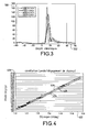
A partir de ces données, la détermination de la quantité de carburant injectée lors de l'injection principale peut être effectuée en évaluant le dégagement DQ de chaleur moyen sur un intervalle centré par rapport à l'injection principale du moteur comme montré sur la figure 3 qui représente les dégagements de chaleur (axe des ordonnées 300), en joules par degré α de vilebrequin (axe des abscisses 302), déterminés pour différents régimes moteurs.From these data, the determination of the amount of fuel injected during the main injection can be performed by evaluating the heat release DQ mean over an interval centered with respect to the injection motor as shown in Figure 3 which represents the heat releases (ordinate axis 300), in joules by degree α of crankshaft (axis of abscissa 302), determined for different engine speeds.
Comme précédemment décrit, de telles mesures de dégagements de chaleur sont obtenues à partir de mesures de la pression dans la chambre de combustion, par exemple au moyen d'un capteur intégré dans la culasse ou dans la bougie de préchauffage.As previously described, such measures of heat releases are obtained from measurements of the pressure in the combustion chamber, for example by means of a sensor integrated in the cylinder head or in the candle of preheating.
Il convient de souligner que les valeurs du volume de la chambre de combustion sont déterminées en fonction de la position du piston, c'est-à-dire de la valeur α de degré vilebrequin du piston.It should be emphasized that the volume values of the combustion chamber are determined according to the piston position, that is to say the degree α piston crankshaft.
On rappelle qu'une valeur α de degrés vilebrequin nulle correspond au point mort haut du piston considéré, les valeurs négatives correspondant à un déplacement de ce piston vers le point mort haut tandis qu'une valeur positive des degrés de vilebrequin correspond à un déplacement du piston vers le point mort bas.It is recalled that a value α of degrees crankshaft zero corresponds to the top dead center of the piston considered, the negative values corresponding to a displacement of this piston towards the top dead center while a positive value of the degrees crankshaft corresponds to a displacement of the piston towards the bottom dead point.
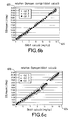
Sur la figure 4 sont représentées des mesures
relatives à la quantité de carburant injectée (axe 400 des
ordonnées), en mg/cycle moteur, dans les cylindres d'un moteur
en fonction du dégagement de chaleur mesuré (axe des abscisses
402), en joules/degré vilebrequin selon le procédé décrit à
l'aide de la figure 3, c'est-à-dire à partir de mesures de
pression dans les chambres de combustion de ces cylindres.In Figure 4 are shown measurements
the quantity of fuel injected (
Ces mesures de carburant, obtenues en pesant au moyen d'une balance la quantité de carburant consommée, sont effectuées à l'aide d'un moteur dont les conditions de fonctionnement (régime moteur, taux de recyclage des gaz d'échappement, pression de suralimentation, avance à l'injection et/ou température au collecteur d'admission) sont fortement modifiées au cours des mesures.These fuel measurements, obtained by weighing of a balance the amount of fuel consumed, are carried out using an engine whose conditions of operation (engine speed, gas recirculation rate exhaust, boost pressure, injection advance and / or temperature at the intake manifold) are strongly modified during the measurements.
On observe que le dégagement de chaleur DQ mesuré est linéaire (courbe 404) par rapport à la quantité de carburant introduite dans le cylindre tandis que l'erreur d'estimation pour différentes quantités de carburant injectées, représentée par l'écart entre les valeurs maximales (courbe 406) et minimales (courbe 408), reste faible, de l'ordre de 0,5 mg pour les différentes consignes K de carburant à injecter.It is observed that the measured heat release DQ is linear (curve 404) in relation to the quantity of fuel introduced into the cylinder while the estimation error for different quantities of fuel injected, represented the difference between the maximum values (curve 406) and minimum (curve 408), remains low, of the order of 0.5 mg for the different instructions K of fuel to inject.
En d'autres termes, l'erreur relative de la mesure par rapport à la quantité K injectée étant d'autant plus faible que la quantité de carburant injectée est importante, la détermination de la quantité de carburant injectée est particulièrement adaptée pour contrôler les injections de carburants importantes, par exemple correspondant à l'injection principale fournissant le couple moteur.In other words, the relative error of the measurement by compared to the injected quantity K being all the weaker than the amount of fuel injected is important, the determination of the amount of fuel injected is particularly suitable for controlling injections of important fuels, for example corresponding to the injection main providing the engine torque.
Il convient de remarquer que les fortes modifications, ou dérives des conditions de fonctionnement du moteur, correspondent à des variations extrêmes, telles que l'ouverture ou la fermeture complète du recyclage de gaz d'échappement, de la température du moteur et de la pression de suralimentation.It should be noted that the strong modifications, or derives from the operating conditions of the engine, correspond to extreme variations, such as the opening or the complete closure of the exhaust gas recirculation, engine temperature and boost pressure.
Dès lors, les variations de fonctionnement du moteur lors d'un fonctionnement normal étant moins importantes, l'erreur sur la détermination de la quantité K de carburant injectée est, en pratique, inférieure à cette marge d'erreur expérimentale.Therefore, the variations of engine operation during normal operation being less important, the error on the determination of the quantity K of fuel injected is, in practice, less than this margin of error Experimental.
Sur la figure 5 sont représentées des évaluations de
carburant injecté (axe des ordonnées 500), en mg/cycle moteur,
en fonction de dégagements DQ de chaleur mesurés (axe des
abscisses 502), en joules/degré de vilebrequin, pour chacun des
trois cylindres testés d'un moteur à quatre cylindres, les
mesures associées à chaque cylindre i étant représentées par une
courbe 500i.FIG. 5 shows injected fuel evaluations (ordinate axis 500), in mg / engine cycle, as a function of measured heat releases DQ (abscissa axis 502), in joules / degree of crankshaft, for each of the three cylinders tested of a four-cylinder engine, the measurements associated with each cylinder i being represented by a
On observe que la linéarité et la faible dispersion des mesures remarquées à la figure 4 sont détectées dans les estimations propres à chaque cylindre de telle sorte qu'une stratégie de correction pour chaque cylindre peut être considérée.We observe that linearity and low dispersion measures noted in Figure 4 are detected in the estimates specific to each cylinder so that a correction strategy for each cylinder can be considered.
De plus, chaque cylindre présente un rapport égal entre le débit injecté et le dégagement DQ de chaleur moyen, seule une déviation verticale variant d'un cylindre à un autre. In addition, each cylinder has an equal ratio between the injected flow rate and the average heat clearance DQ, only a vertical deviation varying from one cylinder to another.
Une telle variation est due aux écarts du coefficient polytropique γ de chaque cylindre liés à la disparité de leurs caractéristiques techniques telles que leurs taux de compression ou la perméabilité de leurs soupapes.Such variation is due to differences in the coefficient polytropic γ of each cylinder related to the disparity of their technical characteristics such as their compression ratios or the permeability of their valves.
C'est pourquoi, comme montré à la figure 6, il
convient d'évaluer le coefficient polytropique yi pour chacun
des trois cylindres i testés, par exemple suivant la formule
Par la suite, on améliore la détermination de la mesure dQ de chaleur de chaque cylindre en ajoutant à cette mesure un terme α(γi-γo) correctif où α représente l'angle de piston et γo est le coefficient polytropique moyen idéal d'un cylindre, à cette mesure.Subsequently, the determination of the measure dQ of heat of each cylinder by adding to this measures a correction term α (γi-γo) where α represents the angle of piston and γo is the ideal average polytropic coefficient of a cylinder, to this extent.
L'effet d'un tel terme correctif est montré à l'aide
des figures 6b et 6c relative à des mesures de dégagement de
chaleur (axe 620 des ordonnées en joules par degré) en fonction
du débit de carburant calculé (axe 622 des abscisses en mg).The effect of such a correction term is shown using
FIGS. 6b and 6c relating to clearance measurements of
heat (
On observe alors que, lorsque le terme correctif α(γi-γo) est appliqué (figure 6b), les écarts entre les mesures propres à chaque cylindre sont moindres que lorsque ce terme n'est pas appliqué (figure 6c).We then observe that when the term corrective α (γi-γo) is applied (Figure 6b), the differences between the measurements each cylinder are less than when this term is not applied (Figure 6c).
En d'autres termes, on obtient des rapports similaires entre les variations dQ de chaleur et le débit de carburant, ce qui facilite les calculs décrits ultérieurement à l'aide de ces coefficients.In other words, we get similar reports between variations of heat and fuel flow, this which facilitates the calculations described later using these coefficients.
La faible sensibilité des mesures de dégagement de
chaleur vis-à-vis du régime moteur et de la pression d'injection
est représentée ci-dessous à l'aide du tableau 1.
Dans ce tableau 1 sont représentées des estimations (colonne «Erreur»), en mg, de l'écart entre la quantité de carburant injectée et la quantité de carburant estimée injectée selon un procédé conforme à l'invention pour différentes quantités commandées (colonne « débit[mg]»).In this table 1 are shown estimates (column "Error"), in mg, of the difference between the quantity of injected fuel and the estimated amount of fuel injected according to a process according to the invention for different quantities ordered (column "flow [mg]").
Cet écart est évalué pour différents régimes (colonne « régime[RPM]») et pressions d'injection (colonne «Pr [bar] »).This difference is evaluated for different schemes (column "RPM") and injection pressures ("Pr [bar]" column).
Il apparaít que les fortes variations du régime, de la pression d'injection ou de la quantité de carburant commandée ne modifient pas de façon importante l'erreur sur l'évaluation de la quantité de carburant injectée.It appears that the strong variations of the regime, the injection pressure or the amount of fuel ordered does not significantly alter the error in the assessment of the amount of fuel injected.
En résumé, la mesure du dégagement de chaleur dans une chambre de combustion est un moyen fiable et précis pour mesurer la quantité de carburant injectée, le dégagement de chaleur étant proportionnel à la quantité de carburant injecté.In summary, the measurement of heat release in a combustion chamber is a reliable and accurate way to measure the quantity of fuel injected, the release of heat being proportional to the amount of fuel injected.
En outre, une mesure du dégagement de chaleur est peu sensible à des variations de paramètres relatifs au fonctionnement du moteur autre que la quantité de carburant injectée.In addition, a measure of heat release is sensitive to variations in parameters relating to engine operation other than the amount of fuel injected.
C'est pourquoi, l'invention concerne un moteur diesel muni d'un dispositif contrôlant l'injection de carburant dans un cylindre au moyen d'un processeur commandant un injecteur du cylindre, caractérisé en ce que le dispositif comprend des moyens pour mesurer un dégagement de chaleur généré par une injection commandée, des moyens pour déterminer un écart entre la quantité de carburant commandée et la quantité de carburant injectée, évaluée à partir du dégagement de chaleur mesuré, et des moyens pour commander l'injecteur en fonction de cet écart.This is why the invention relates to a diesel engine equipped with a device controlling the injection of fuel into a cylinder by means of a processor controlling an injector cylinder, characterized in that the device comprises means for measuring a heat release generated by a controlled injection, means to determine a difference between the amount of fuel ordered and the amount of fuel injected, evaluated from the measured heat release, and means for controlling the injector as a function of this difference.
Grâce à l'invention, il est ainsi possible de corriger des écarts de fonctionnement d'un injecteur par une mesure de dégagement de chaleur, fonction de la quantité de carburant réellement injectée dans le cylindre.Thanks to the invention, it is thus possible to correct operating differences of an injector by a measurement of heat release, depending on the amount of fuel actually injected into the cylinder.
Dès lors, la correction des écarts d'injection selon l'invention présente les avantages précédemment identifiés, à savoir que la mesure des dégagements de chaleur est fortement sensible à la quantité de carburant injectée et faiblement modifiée par des variations d'autres paramètres de fonctionnement du moteur.Therefore, the correction of injection differences according to the invention has the advantages previously identified, know that the measurement of heat releases is strongly sensitive to the amount of fuel injected and weakly modified by variations of other parameters of engine operation.
Dans un mode de réalisation, l'écart est déterminé en comparant le dégagement (DQmes) mesuré avec un dégagement (DQpré) de chaleur prédéterminé.In one embodiment, the difference is determined by comparing the measured clearance (DQ mes ) with a predetermined pre -heat clearance (DQ).
Dans une réalisation, l'écart est déterminé en comparant une quantité de carburant injectée associée à un dégagement de chaleur mesuré, avec une quantité de carburant prédéterminée, associée à un dégagement de chaleur prédéterminé.In one embodiment, the difference is determined by comparing a quantity of injected fuel associated with a measured heat release, with a quantity of fuel predetermined, associated with a predetermined heat release.
Dans ce cas, l'écart de fonctionnement de l'injecteur est déterminé comme l'écart entre la quantité de carburant réellement admise et la quantité de carburant commandée. Il est possible de commander l'injecteur de façon à corriger cet écart afin que la quantité de carburant admise corresponde à la quantité de carburant commandée.In this case, the operating gap of the injector is determined as the difference between the amount of fuel actually admitted and the amount of fuel ordered. It is possible to control the injector so as to correct this gap so that the quantity of fuel accepted corresponds to the quantity of fuel ordered.
Selon une réalisation, le dispositif comprend des moyens pour mesurer le dégagement de chaleur à partir de mesures de la pression dans la chambre de combustion du cylindre.According to one embodiment, the device comprises means for measuring heat release from measurements pressure in the cylinder's combustion chamber.
Dans une réalisation, le dispositif comprend des moyens pour effectuer des mesures de pression pendant une durée au cours de laquelle s'effectue l'injection principale de carburant dans le cylindre. In one embodiment, the device comprises means for performing pressure measurements for a period of time during which the main injection of fuel in the cylinder.
Selon une réalisation, le dispositif comprend des moyens pour que la durée corresponde à un avancement du cycle moteur d'au moins soixante degrés vilebrequin.According to one embodiment, the device comprises means so that the duration corresponds to a progress of the cycle engine of at least sixty degrees crankshaft.
Selon une réalisation, le dispositif comprend des
moyens pour mesurer le dégagement de chaleur à partir de
dégagements élémentaires déterminés au moyen de la formule :
Selon un mode de réalisation, le dispositif comprend
des moyens pour déterminer les paramètres a et b en fonction du
coefficient polytropique γ du cylindre défini comme :
Dans un mode de réalisation, le dispositif comprend des moyens pour commander une pluralité d'injections de carburants identiques, des moyens pour mesurer un dégagement de chaleur propre à chaque injection et des moyens pour associer un dégagement de chaleur à l'injection répétée correspondant à la moyenne des dégagements de chaleur mesurés à chaque injection.In one embodiment, the device comprises means for controlling a plurality of injections of identical fuels, means for measuring a clearance of heat to each injection and means to associate a repeated injection of heat corresponding to the average of the heat releases measured at each injection.
Selon un mode de réalisation, le dispositif comprend des moyens pour mémoriser les dégagements de chaleur mesurés, par exemple sous la forme d'une cartographie, en fonction de la durée d'activation de l'injecteur utilisé pour déterminer ce dégagement.According to one embodiment, the device comprises means for storing the measured heat releases, for example in the form of a map, depending on the activation time of the injector used to determine this clearance.
Dans une réalisation, une durée d'activation commandée étant associée à un dégagement de chaleur prédéterminé, le dispositif comprend des moyens pour modifier une durée d'activation commandée en fonction de l'écart entre cette dernière et la durée utilisée pour mesurer un dégagement de chaleur identique au dégagement de chaleur prédéterminé associé à la durée commandée.In one embodiment, a controlled activation duration being associated with a predetermined heat release, the device includes means for changing a duration controlled activation based on the gap between this last and the duration used to measure a clearance from heat identical to the associated predetermined heat release to the ordered duration.
Selon une réalisation, le dispositif comprend des moyens pour mesurer un dégagement de chaleur en fonction de la pression d'injection et de la quantité de carburant commandées.According to one embodiment, the device comprises means for measuring a heat release according to the injection pressure and the amount of fuel ordered.
Selon une réalisation, le dispositif comprend des moyens d'inhibition d'une injection pilote pendant un cycle moteur au cours duquel est mesuré un dégagement de chaleur.According to one embodiment, the device comprises means for inhibiting a pilot injection during a cycle engine during which heat generation is measured.
Dans une réalisation, le moteur comprend des moyens pour commander des injections de carburant supérieures à 10 mg.In one embodiment, the engine comprises means to order fuel injections greater than 10 mg.
Dans une réalisation, le moteur comprend une rampe commune d'alimentation de différents cylindres.In one embodiment, the engine comprises a ramp common supply of different cylinders.
D'autres caractéristiques et avantages de l'invention apparaítront avec la description de certains de ses modes de réalisation effectuée ci-dessous, à titre non limitatif, en se référant aux dessins ci-annexés sur lesquels :
- la figure 1, déjà décrite, représente un moteur à rampe commune,
- la figure 2, déjà décrite, représente les variations d'injection entre un injecteur modélisé et des injecteurs usés,
- la figure 3, déjà décrite, représente des mesures de dégagement de chaleur en fonction de l'avancement du cycle de combustion dans un moteur,
- les figures 4
et 5, déjà décrites, représentent la corrélation entre des dégagements de chaleur mesurés et des quantités de carburant injectées, - les figures 6, 6b et 6c, déjà décrites, représentent des variations du coefficient polytropique associées au mélange de carburant introduit dans les cylindres et l'influence d'une correction de ces variations dans les mesures de chaleur,
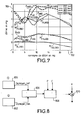
- la figure 7 représente des dérives de fonctionnement d'injecteurs de carburant en fonction de la pression et de la quantité de carburant commandée et la modélisation de ces dérives selon une réalisation de l'invention,
- la figure 8 représente une suite d'opérations corrigeant les durées d'activation d'un injecteur conformément à une réalisation de l'invention,
- la figure 9 représente une suite d'opérations pour établir une cartographie conforme à l'invention,
- la figure 10 représente une linéarisation de données conforme à une réalisation de l'invention,
- la figure 11 représente une variante de l'invention commandant un injecteur à partir de calculs propres à des débits commandés et mesurés, et
- la figure 12 représente une mise en oeuvre de la variante décrite à la figure 11.
- FIG. 1, already described, represents a common-rail motor,
- FIG. 2, already described, represents the injection variations between a modeled injector and worn injectors,
- FIG. 3, already described, represents measurements of heat evolution as a function of the advance of the combustion cycle in an engine,
- FIGS. 4 and 5, already described, represent the correlation between measured heat releases and injected quantities of fuel,
- FIGS. 6, 6b and 6c, already described, represent variations in the polytropic coefficient associated with the mixture of fuel introduced into the cylinders and the influence of a correction of these variations in the heat measurements,
- FIG. 7 represents operating drifts of fuel injectors as a function of the pressure and the quantity of fuel ordered and the modeling of these drifts according to one embodiment of the invention,
- FIG. 8 represents a sequence of operations correcting the activation times of an injector according to one embodiment of the invention,
- FIG. 9 represents a series of operations for establishing a map according to the invention,
- FIG. 10 represents a linearization of data according to an embodiment of the invention,
- FIG. 11 represents a variant of the invention controlling an injector from calculations specific to controlled and measured flow rates, and
- FIG. 12 represents an implementation of the variant described in FIG. 11.
Conformément à l'invention, la réalisation de l'invention décrite ci-dessous concerne un moteur diesel muni d'un dispositif à injecteur comprenant des moyens pour mesurer un dégagement de chaleur généré par une injection de carburant, des moyens pour comparer ce dégagement mesuré avec un dégagement de chaleur prédéterminé et des moyens pour commander l'injecteur en fonction de cette comparaison.According to the invention, the realization of the invention described below relates to a diesel engine provided with an injector device comprising means for measuring a release of heat generated by a fuel injection, ways to compare that measured clearance with a clearance predetermined heat and means for controlling the injector according to this comparison.
Une première analyse de ce moteur est montrée à la figure 7, où sont représentées des mesures de dérives ou d'écarts de fonctionnement d'un injecteur pour différentes pressions Pr d'injection, à savoir 230 bars, 400 bars, 800 bars et 1200 bars.A first analysis of this engine is shown in the FIG. 7, which shows drift measurements or of operating differences of an injector for different injection pressures Pr, namely 230 bar, 400 bar, 800 bar and 1200 bars.
La dérive correspondant à chaque pression i est
représentée par une courbe αPr établi e selon un axe 700 des
ordonnées (en mg) en fonction des différentes quantités de
carburant commandées (axe des abscisses 702, en mg). The drift corresponding to each pressure i is represented by a curve α Pr established along an
On observe que la dérive de l'injecteur varie fortement en fonction de la pression Pr d'injection du carburant ainsi que de la quantité K de carburant commandée.It is observed that the drift of the injector varies greatly depending on the fuel injection pressure P r as well as the quantity K of fuel that is controlled.
C'est pourquoi, dans cette réalisation de l'invention, la correction de la dérive d'un injecteur est effectuée en fonction de la pression Pr à l'injection et de la quantité K de carburant commandée à cet injecteur.Therefore, in this embodiment of the invention, the correction of the drift of an injector is effected as a function of the pressure P r at the injection and the quantity K of fuel controlled at this injector.
A cet effet, différentes mesures de dégagement de
chaleur sont effectuées pour différentes pression Pr d'injection
et pour différentes consignes de débit comme représenté sur le
tableau 2 ci-dessous.
débit
en (mg)
debit
in (mg)
Un tel tableau 2 représente une cartographie des mesures de dégagements de chaleur dans la chambre de combustion alimentée par l'injecteur testé en fonction de la consigne K et de la pression Pr d'injection.Such a table 2 represents a map of the heat removal measurements in the combustion chamber fed by the injector tested as a function of the set point K and the injection pressure P r .
A l'aide d'une telle cartographie, il est possible de connaítre la valeur du dégagement de chaleur (DQK,Pr) mesuré pour une consigne K (5, 10, 15, 20 et 25 mg) et pour une pression Pr à l'injection (230, 400, 600, 800, 1000 et 1200) déterminées.Using such a mapping, it is possible to know the value of the heat release (DQ K, Pr ) measured for a K setpoint (5, 10, 15, 20 and 25 mg) and for a pressure P r at the injection (230, 400, 600, 800, 1000 and 1200) determined.
De fait, comme montré à la figure 7, les dégagements de chaleur mesurés en fonction de la consigne K peuvent être modélisés par des segments M(K,Pr) continus définis, à ces extrémités, par les mesures de dégagements de chaleur suivant un écart de 5 mg.In fact, as shown in FIG. 7, the heat releases measured as a function of the setpoint K can be modeled by continuous segments M (K, Pr) defined at these ends by the measurements of heat evolution following a gap. of 5 mg.
A partir d'une telle cartographie, il est possible de déterminer l'écart entre la quantité de carburant commandée et la quantité de carburant réellement injectée par un injecteur, puis de corriger cet écart comme montré ci-dessous à l'aide de la figure 8.From such a map, it is possible to determine the difference between the quantity of fuel ordered and the amount of fuel actually injected by an injector, then correct this gap as shown below using Figure 8.
Sur cette figure 8 est représentée une cartographie
802 utilisant des mesures de dégagements DQmes de chaleur de
l'injecteur considéré, par exemple telles que déterminées dans
le tableau 2, et une cartographie 804 prédéterminée, identifiant
des dégagements DQpré de chaleur définis au moyen du
fonctionnement modélisé de l'injecteur.In this Figure 8 shows a
En comparant (opération 806) les dégagements DQmes de chaleur mesurés aux dégagements DQpre de chaleurs prédéterminés, pour une même consigne K et une même pression Pr d'injection, une différence de dégagement de chaleur DQmes - DQpré peut être définie.Comparing (step 806) clearances DQ my heat measured at pre DQ clearances predetermined heat, for a given set K and the same pressure Pr injection, an exotherm difference DQ my - DQ pre can be defined.
Cette différence DQmes - DQpré correspond à un écart DK de quantité de carburant injectée qui peut se traduire en un délai Dt d'activation, positif ou négatif, correspondant à l'écart de fonctionnement de l'injecteur.This difference DQ mes - DQ pre corresponds to a difference DK fuel quantity injected which can result in a Dt activation time, positive or negative, corresponding to the operating gap of the injector.
A cet effet, on multiplie l'écart DK de quantité de carburant injectée par un coefficient Ck correspondant à la pente de la courbe reliant le dégagement de chaleur à la quantité de carburant injectée (figure 5).For this purpose, the difference DK of fuel quantity injected is multiplied by a coefficient C k corresponding to the slope of the curve connecting the evolution of heat to the quantity of fuel injected (FIG. 5).
Les écarts Dt d'activation sont calculés pour les différentes valeurs de pression Pr d'injection et de quantité K de carburant commandées de telle sorte que, lorsqu'un délai αt d'activation est commandé à l'injecteur, la pression Pr d'injection et la consigne K sont prises en compte pour déterminer (opération 808) l'écart Dt utilisé pour corriger (bloc 810) le délai αt commandé.The activation deviations Dt are calculated for the different pressure values Pr of injection and quantity K controlled fuel so that when a delay has elapsed activation is controlled by the injector, the pressure Pr injection and the K setpoint are taken into account for determine (operation 808) the difference Dt used to correct (block 810) the delay αt commanded.
Il convient de signaler que, comme décrit ultérieurement dans une réalisation de l'invention, les écarts DK de consigne peuvent être directement utilisés pour corriger la consigne K appliquée.It should be noted that as described subsequently in one embodiment of the invention, the differences DK setpoint can be directly used to correct the setpoint K applied.
Sur la figure 9 sont représentées diverses opérations effectuées lors de la mesure d'un dégagement de chaleur.In Figure 9 are shown various operations performed when measuring heat release.
Dans un premier temps, lorsqu'une mesure de dégagement de chaleur est commandée (bloc 900), par exemple de façon horaire, la consigne de l'injection principale est égalée à la valeur K (bloc 902) pour laquelle une mesure est requise tandis que la consigne de l'injection pilote, utilisée pour établir des conditions de combustion optimales dans le cylindre, est mise à zéro.At first, when a release action of heat is controlled (block 900), for example time, the instruction of the main injection is equal to the K value (block 902) for which a measurement is required while the instruction of the pilot injection, used to establish optimal combustion conditions in the cylinder, is set to zero.
Dans un deuxième temps, les paramètres de mesure des dégagements de chaleur sont établis (bloc 910) de telle sorte que le dégagement de chaleur soit évalué sur une moyenne de 60 degrés vilebrequin (bloc 911).In a second step, the measurement parameters of heat releases are established (block 910) so that the release of heat is evaluated on an average of 60 crankshaft degrees (block 911).
Dans un troisième temps (bloc 912), la consigne K de carburant injecté est appliquée tandis que la pression Pr d'injection est maintenue à une des valeurs de mesures précédemment définies pendant que les mesures de dégagements de chaleur sont effectuées.In a third step (block 912), the instruction K of injected fuel is applied while pressure Pr Injection is maintained at one of the measurement values previously defined while the clearance measures of heat are performed.
Dans cette réalisation de l'invention, chaque mesure du dégagement de chaleur DQmes(Pr, K), correspondant à une pression d'injection Pr et à une consigne K, résulte de la moyenne de dix valeurs mesurées.In this embodiment of the invention, each measurement of the heat release DQ mes (Pr, K), corresponding to an injection pressure Pr and a setpoint K, results from the average of ten measured values.
De fait, comme montré sur la figure 10, les mesures
100 de dégagements de chaleur sont linéarisées de façon à
disposer d'une mesure de dégagement de chaleur DQmes (Pr, K) pour
toute pression d'injection. Dans cette réalisation, ces mesures
sont linéarisées suivant des intervalles de 200 bars.In fact, as shown in FIG. 10, the
Il convient de signaler que la cartographie des mesures de dégagements est effectuée cylindre par cylindre.It should be noted that the mapping of Clearance measurements are performed cylinder by cylinder.
Par ailleurs, lors des mesures des dégagements de chaleur, un filtre est utilisé de façon à éliminer les perturbations dues aux vibrations du moteur. Moreover, when measuring the clearances of heat, a filter is used to eliminate the disturbances due to engine vibration.
La présente invention est susceptible de nombreuses variantes. Par exemple, les opérations de détermination des écarts de fonctionnement peuvent être effectuées en comparant une (ou plusieurs) mesure(s) du débit de carburant injecté par rapport au(x) débit(s) commandé(s) (consignés) de façon à corriger les délais d'activation d'un injecteur d'une durée correspondant à l'écart mesuré.The present invention is susceptible of many variants. For example, the operations for determining operating differences can be made by comparing one (or more) measure (s) of the fuel flow injected by the flow (s) ordered (recorded) in order to correct the activation time of an injector of a duration corresponding to the measured difference.
A cet effet, comme montré à la figure 11, on peut déterminer et utiliser la relation f (K) entre la quantité de carburant commandée (K1) et la quantité de carburant réellement admise (K2), déterminée au moyen du dégagement de chaleur comme précédemment indiqué, de telle sorte que, lorsqu'une consigne K1 de carburant est commandée, la consigne de débit K2 soit réellement prise en compte.For this purpose, as shown in FIG. 11, it is possible to determine and use the relation f (K) between the quantity of fuel controlled (K 1 ) and the quantity of fuel actually admitted (K 2 ), determined by means of the clearance of heat as previously indicated, so that when a fuel K 1 setpoint is controlled, the flow setpoint K 2 is actually taken into account.
Un tel contrôle des débits commandés peut être mis en
oeuvre au moyen d'un correcteur 1200 (figure 12) corrigeant la
consigne 1220 commandée par un terme 1240 correcteur (K1-K2),
égal à l'écart entre la quantité de carburant commandé et la
quantité de carburant réellement injecté, déterminé au moyen
d'une cartographie 1260.Such control of the controlled flow rates can be implemented by means of a corrector 1200 (FIG. 12) correcting the
Un tel écart DK peut être déterminé à partir d'une cartographie, telle que décrite à la figure 11, obtenue de façon analogue à la cartographie décrite à la figure 7 à partir des écarts mesurés entre le dégagement de chaleur mesuré et le dégagement de chaleur prédéterminé pour une consigne de carburant donnée.Such a difference DK can be determined from a cartography, as described in Figure 11, so obtained similar to the mapping described in Figure 7 from measured differences between the measured heat release and the predetermined heat release for a set of given fuel.
Dans ce cas, les opérations décrites aux figures 8 et
9 sont effectuées en considérant l'écart dK de consigne de
carburant à la place de l'écart dQ de dégagement de chaleur, de
façon à établir leur relation (figure 10) entre la pression de
carburant dans la rampe commune (axe 1000, en bars) et le débit
de carburant injecté.In this case, the operations described in FIGS.
9 are performed considering the difference dK of setpoint of
fuel instead of the difference in heat release,
to establish their relationship (Figure 10) between the pressure of
fuel in the common rail (
Claims (15)
Applications Claiming Priority (2)
| Application Number | Priority Date | Filing Date | Title |
|---|---|---|---|
| FR0213502A FR2846373B1 (en) | 2002-10-29 | 2002-10-29 | DIESEL ENGINE HAVING FUEL INJECTION FLOW CONTROL DEVICE |
| FR0213502 | 2002-10-29 |
Publications (2)
| Publication Number | Publication Date |
|---|---|
| EP1429009A1 true EP1429009A1 (en) | 2004-06-16 |
| EP1429009B1 EP1429009B1 (en) | 2005-12-07 |
Family
ID=32088362
Family Applications (1)
| Application Number | Title | Priority Date | Filing Date |
|---|---|---|---|
| EP03300180A Expired - Lifetime EP1429009B1 (en) | 2002-10-29 | 2003-10-28 | Diesel engine with fuel injection quantity control apparatus |
Country Status (4)
| Country | Link |
|---|---|
| EP (1) | EP1429009B1 (en) |
| AT (1) | ATE312280T1 (en) |
| DE (1) | DE60302636T2 (en) |
| FR (1) | FR2846373B1 (en) |
Cited By (5)
| Publication number | Priority date | Publication date | Assignee | Title |
|---|---|---|---|---|
| EP2184472A1 (en) | 2008-11-10 | 2010-05-12 | Delphi Technologies Holding S.à.r.l. | Engine Control System and Method |
| CN102606328A (en) * | 2012-03-23 | 2012-07-25 | 潍柴动力股份有限公司 | Method and system for controlling oil injection according to wearing degree of oil injector |
| CN104838116A (en) * | 2012-12-18 | 2015-08-12 | 法国大陆汽车公司 | Method for determining the amount of fuel injected into an engine, in particular a diesel engine |
| EP2971712A1 (en) * | 2013-03-12 | 2016-01-20 | Westport Power Inc. | Fuel system diagnostics |
| EP2550447A4 (en) * | 2010-03-23 | 2016-06-01 | Scania Cv Abp | Method for determining a relationship between the operating time for an injector of a cylinder in a combustion engine and the amount of fuel injected by the injector |
Families Citing this family (8)
| Publication number | Priority date | Publication date | Assignee | Title |
|---|---|---|---|---|
| JP4081819B2 (en) | 2004-05-06 | 2008-04-30 | 株式会社デンソー | Fuel injection system |
| FR2872282B1 (en) * | 2004-06-28 | 2007-04-20 | Renault Sas | PROCESS FOR PROCESSING A PRESSURE SIGNAL |
| FR2890117B1 (en) * | 2005-08-30 | 2009-07-10 | Peugeot Citroen Automobiles Sa | METHOD AND SYSTEM FOR MONITORING THE OPERATION OF A DIESEL ENGINE OF A MOTOR VEHICLE |
| FR2975136B1 (en) | 2011-05-13 | 2014-11-21 | Continental Automotive France | METHOD FOR DETERMINING THE FUEL QUANTITY EXCEEDING AN INJECTOR |
| GB2498784A (en) * | 2012-01-27 | 2013-07-31 | Gm Global Tech Operations Inc | Method of controlling an internal combustion engine which allows for the delay between the fuel injection and the time at which the fuel burns |
| EP2754878A1 (en) * | 2013-01-15 | 2014-07-16 | Robert Bosch Gmbh | Method of operating a combustion engine |
| DE102013202038B3 (en) * | 2013-02-07 | 2013-07-25 | Mtu Friedrichshafen Gmbh | Method for correction of amount of fuel injected by fuel injector in operation of combustion engine, involves calculating engine supplied fuel mass from one of air and exhaust heat characteristics, and heat distribution factors |
| DE102020203887B4 (en) | 2020-03-25 | 2023-11-02 | Rolls-Royce Solutions GmbH | Method for operating an internal combustion engine, control device set up to carry out such a method, and internal combustion engine with such a control device |
Citations (5)
| Publication number | Priority date | Publication date | Assignee | Title |
|---|---|---|---|---|
| US4513714A (en) * | 1982-02-03 | 1985-04-30 | Steyr-Daimler-Puch Aktiengesellschaft | Method of adjusting a plurality of fuel injection units associated with respective cylinders of a multi-cylinder diesel engine |
| EP0864738A2 (en) * | 1997-03-10 | 1998-09-16 | Toyota Jidosha Kabushiki Kaisha | Fuel injection controller for diesel engines |
| EP0971115A2 (en) * | 1998-07-08 | 2000-01-12 | Isuzu Motors Limited | Common-rail fuel injection system |
| US6062193A (en) * | 1996-09-27 | 2000-05-16 | Institut Francais Du Petrole | Process for controlling the quantity of fuel injected into a diesel engine |
| US6102005A (en) * | 1998-02-09 | 2000-08-15 | Caterpillar Inc. | Adaptive control for power growth in an engine equipped with a hydraulically-actuated electronically-controlled fuel injection system |
-
2002
- 2002-10-29 FR FR0213502A patent/FR2846373B1/en not_active Expired - Fee Related
-
2003
- 2003-10-28 DE DE60302636T patent/DE60302636T2/en not_active Expired - Lifetime
- 2003-10-28 AT AT03300180T patent/ATE312280T1/en not_active IP Right Cessation
- 2003-10-28 EP EP03300180A patent/EP1429009B1/en not_active Expired - Lifetime
Patent Citations (5)
| Publication number | Priority date | Publication date | Assignee | Title |
|---|---|---|---|---|
| US4513714A (en) * | 1982-02-03 | 1985-04-30 | Steyr-Daimler-Puch Aktiengesellschaft | Method of adjusting a plurality of fuel injection units associated with respective cylinders of a multi-cylinder diesel engine |
| US6062193A (en) * | 1996-09-27 | 2000-05-16 | Institut Francais Du Petrole | Process for controlling the quantity of fuel injected into a diesel engine |
| EP0864738A2 (en) * | 1997-03-10 | 1998-09-16 | Toyota Jidosha Kabushiki Kaisha | Fuel injection controller for diesel engines |
| US6102005A (en) * | 1998-02-09 | 2000-08-15 | Caterpillar Inc. | Adaptive control for power growth in an engine equipped with a hydraulically-actuated electronically-controlled fuel injection system |
| EP0971115A2 (en) * | 1998-07-08 | 2000-01-12 | Isuzu Motors Limited | Common-rail fuel injection system |
Cited By (8)
| Publication number | Priority date | Publication date | Assignee | Title |
|---|---|---|---|---|
| EP2184472A1 (en) | 2008-11-10 | 2010-05-12 | Delphi Technologies Holding S.à.r.l. | Engine Control System and Method |
| EP2550447A4 (en) * | 2010-03-23 | 2016-06-01 | Scania Cv Abp | Method for determining a relationship between the operating time for an injector of a cylinder in a combustion engine and the amount of fuel injected by the injector |
| CN102606328A (en) * | 2012-03-23 | 2012-07-25 | 潍柴动力股份有限公司 | Method and system for controlling oil injection according to wearing degree of oil injector |
| CN102606328B (en) * | 2012-03-23 | 2014-12-31 | 潍柴动力股份有限公司 | Method and system for controlling oil injection according to wearing degree of oil injector |
| CN104838116A (en) * | 2012-12-18 | 2015-08-12 | 法国大陆汽车公司 | Method for determining the amount of fuel injected into an engine, in particular a diesel engine |
| EP2971712A1 (en) * | 2013-03-12 | 2016-01-20 | Westport Power Inc. | Fuel system diagnostics |
| EP2971712A4 (en) * | 2013-03-12 | 2017-06-28 | Westport Power Inc. | Fuel system diagnostics |
| US10519888B2 (en) | 2013-03-12 | 2019-12-31 | Westport Power Inc. | Fuel system diagnostics |
Also Published As
| Publication number | Publication date |
|---|---|
| FR2846373A1 (en) | 2004-04-30 |
| DE60302636T2 (en) | 2006-10-19 |
| FR2846373B1 (en) | 2006-06-16 |
| DE60302636D1 (en) | 2006-01-12 |
| EP1429009B1 (en) | 2005-12-07 |
| ATE312280T1 (en) | 2005-12-15 |
Similar Documents
| Publication | Publication Date | Title |
|---|---|---|
| EP1429009B1 (en) | Diesel engine with fuel injection quantity control apparatus | |
| FR2922598A1 (en) | PROCESS FOR DETERMINING THE FLAMMABILITY OF FUEL OF UNKNOWN QUALITY. | |
| FR2910060A1 (en) | METHOD FOR DETERMINING INDIVIDUAL CYLINDER COMBUSTION CHARACTERISTICS OF AN INTERNAL COMBUSTION ENGINE | |
| FR2875548A1 (en) | METHOD AND DEVICE FOR CONTROLLING AN INTERNAL COMBUSTION ENGINE | |
| FR2811713A1 (en) | PROCESS AND DEVICE FOR BALANCING AN INTERNAL COMBUSTION ENGINE | |
| FR2905420A1 (en) | METHOD FOR MANAGING A COMBUSTION ENGINE | |
| FR2762647A1 (en) | METHOD FOR DETERMINING THE DURATION OF INJECTION IN A DIRECT INJECTION INTERNAL COMBUSTION ENGINE | |
| EP2148979B1 (en) | Method of controlling the combustion of a diesel engine | |
| FR3028891B1 (en) | METHOD FOR STARTING A DIRECT INJECTION INTERNAL COMBUSTION ENGINE BY ADAPTING THE INJECTED FUEL QUANTITY | |
| WO2019110882A1 (en) | System and method for controlling an internal combustion engine provided with an exhaust gas post-treatment system of the selective catalysis type | |
| EP1499803B1 (en) | Diesel engine comprising a device for controlling the flow of injected fuel | |
| FR2787512A1 (en) | METHOD AND DEVICE FOR CONTROLLING AN INTERNAL COMBUSTION ENGINE | |
| FR2790515A1 (en) | METHOD AND DEVICE FOR IMPLEMENTING THE TRANSIENT OPERATION OF AN INTERNAL COMBUSTION ENGINE, IN PARTICULAR OF A MOTOR VEHICLE | |
| FR2847944A1 (en) | I.c. engine fuel/air mixture regulating procedure with multiple injection consists of adjusting fuel mass on each injection operation | |
| FR2901848A1 (en) | METHOD AND DEVICE FOR CORRECTING THE RATE OF PILOT FUEL INJECTION IN A DIRECT INJECTION DIESEL ENGINE OF THE COMMON RAIL TYPE, AND MOTOR COMPRISING SUCH A DEVICE | |
| FR3024234A1 (en) | METHOD FOR DETERMINING PRESSURE IN THE CYLINDER OF AN ENGINE | |
| FR2857057A1 (en) | Fuel injection system controlling method for internal combustion engine, involves transforming one correction function, by using individual quality characteristics of injectors, to another function to correct injector control signals | |
| FR2808051A1 (en) | METHOD FOR IMPLEMENTING A HEAT ENGINE, HEAT ENGINE APPLYING THE METHOD AND MEANS FOR CARRYING OUT THE METHOD | |
| FR2724417A1 (en) | METHOD FOR CONTROLLING A DIRECT INJECTION INTERNAL COMBUSTION ENGINE | |
| FR3102512A1 (en) | Method of regulating pressure in a water injection system for an internal combustion engine | |
| EP1916404A1 (en) | Method of estimating characteristic parameters of a heat engine and of controlling thermal flux applied to components of this engine | |
| FR2762675A1 (en) | METHOD FOR DETERMINING THE COMPRESSION PRESSURE IN THE CYLINDER OF AN INTERNAL COMBUSTION ENGINE WITH DIRECT FUEL INJECTION | |
| FR2527691A1 (en) | METHOD FOR CONTROLLING CONTROL DEVICES OF INTERNAL COMBUSTION ENGINES IMMEDIATELY AFTER THE END OF A FUEL CUT | |
| EP2134947A2 (en) | Internal combustion engine with adjustment of the injected fuel amount, and method for establishing an injected fuel set point value | |
| EP2034164B1 (en) | Method of injecting fuel in an internal combustion engine |
Legal Events
| Date | Code | Title | Description |
|---|---|---|---|
| PUAI | Public reference made under article 153(3) epc to a published international application that has entered the european phase |
Free format text: ORIGINAL CODE: 0009012 |
|
| AK | Designated contracting states |
Kind code of ref document: A1 Designated state(s): AT BE BG CH CY CZ DE DK EE ES FI FR GB GR HU IE IT LI LU MC NL PT RO SE SI SK TR |
|
| AX | Request for extension of the european patent |
Extension state: AL LT LV MK |
|
| 17P | Request for examination filed |
Effective date: 20041216 |
|
| AKX | Designation fees paid |
Designated state(s): AT BE BG CH CY CZ DE DK EE ES FI FR GB GR HU IE IT LI LU MC NL PT RO SE SI SK TR |
|
| GRAP | Despatch of communication of intention to grant a patent |
Free format text: ORIGINAL CODE: EPIDOSNIGR1 |
|
| GRAS | Grant fee paid |
Free format text: ORIGINAL CODE: EPIDOSNIGR3 |
|
| GRAA | (expected) grant |
Free format text: ORIGINAL CODE: 0009210 |
|
| AK | Designated contracting states |
Kind code of ref document: B1 Designated state(s): AT BE BG CH CY CZ DE DK EE ES FI FR GB GR HU IE IT LI LU MC NL PT RO SE SI SK TR |
|
| PG25 | Lapsed in a contracting state [announced via postgrant information from national office to epo] |
Ref country code: IT Free format text: LAPSE BECAUSE OF FAILURE TO SUBMIT A TRANSLATION OF THE DESCRIPTION OR TO PAY THE FEE WITHIN THE PRESCRIBED TIME-LIMIT;WARNING: LAPSES OF ITALIAN PATENTS WITH EFFECTIVE DATE BEFORE 2007 MAY HAVE OCCURRED AT ANY TIME BEFORE 2007. THE CORRECT EFFECTIVE DATE MAY BE DIFFERENT FROM THE ONE RECORDED. Effective date: 20051207 Ref country code: AT Free format text: LAPSE BECAUSE OF FAILURE TO SUBMIT A TRANSLATION OF THE DESCRIPTION OR TO PAY THE FEE WITHIN THE PRESCRIBED TIME-LIMIT Effective date: 20051207 Ref country code: GB Free format text: LAPSE BECAUSE OF FAILURE TO SUBMIT A TRANSLATION OF THE DESCRIPTION OR TO PAY THE FEE WITHIN THE PRESCRIBED TIME-LIMIT Effective date: 20051207 Ref country code: NL Free format text: LAPSE BECAUSE OF FAILURE TO SUBMIT A TRANSLATION OF THE DESCRIPTION OR TO PAY THE FEE WITHIN THE PRESCRIBED TIME-LIMIT Effective date: 20051207 Ref country code: IE Free format text: LAPSE BECAUSE OF FAILURE TO SUBMIT A TRANSLATION OF THE DESCRIPTION OR TO PAY THE FEE WITHIN THE PRESCRIBED TIME-LIMIT Effective date: 20051207 Ref country code: SI Free format text: LAPSE BECAUSE OF FAILURE TO SUBMIT A TRANSLATION OF THE DESCRIPTION OR TO PAY THE FEE WITHIN THE PRESCRIBED TIME-LIMIT Effective date: 20051207 Ref country code: FI Free format text: LAPSE BECAUSE OF FAILURE TO SUBMIT A TRANSLATION OF THE DESCRIPTION OR TO PAY THE FEE WITHIN THE PRESCRIBED TIME-LIMIT Effective date: 20051207 Ref country code: RO Free format text: LAPSE BECAUSE OF FAILURE TO SUBMIT A TRANSLATION OF THE DESCRIPTION OR TO PAY THE FEE WITHIN THE PRESCRIBED TIME-LIMIT Effective date: 20051207 Ref country code: SK Free format text: LAPSE BECAUSE OF FAILURE TO SUBMIT A TRANSLATION OF THE DESCRIPTION OR TO PAY THE FEE WITHIN THE PRESCRIBED TIME-LIMIT Effective date: 20051207 Ref country code: CZ Free format text: LAPSE BECAUSE OF FAILURE TO SUBMIT A TRANSLATION OF THE DESCRIPTION OR TO PAY THE FEE WITHIN THE PRESCRIBED TIME-LIMIT Effective date: 20051207 |
|
| REG | Reference to a national code |
Ref country code: GB Ref legal event code: FG4D Free format text: NOT ENGLISH |
|
| REG | Reference to a national code |
Ref country code: CH Ref legal event code: EP |
|
| REG | Reference to a national code |
Ref country code: IE Ref legal event code: FG4D Free format text: LANGUAGE OF EP DOCUMENT: FRENCH |
|
| REF | Corresponds to: |
Ref document number: 60302636 Country of ref document: DE Date of ref document: 20060112 Kind code of ref document: P |
|
| PG25 | Lapsed in a contracting state [announced via postgrant information from national office to epo] |
Ref country code: GR Free format text: LAPSE BECAUSE OF FAILURE TO SUBMIT A TRANSLATION OF THE DESCRIPTION OR TO PAY THE FEE WITHIN THE PRESCRIBED TIME-LIMIT Effective date: 20060307 Ref country code: DK Free format text: LAPSE BECAUSE OF FAILURE TO SUBMIT A TRANSLATION OF THE DESCRIPTION OR TO PAY THE FEE WITHIN THE PRESCRIBED TIME-LIMIT Effective date: 20060307 Ref country code: BG Free format text: LAPSE BECAUSE OF FAILURE TO SUBMIT A TRANSLATION OF THE DESCRIPTION OR TO PAY THE FEE WITHIN THE PRESCRIBED TIME-LIMIT Effective date: 20060307 Ref country code: SE Free format text: LAPSE BECAUSE OF FAILURE TO SUBMIT A TRANSLATION OF THE DESCRIPTION OR TO PAY THE FEE WITHIN THE PRESCRIBED TIME-LIMIT Effective date: 20060307 |
|
| PG25 | Lapsed in a contracting state [announced via postgrant information from national office to epo] |
Ref country code: ES Free format text: LAPSE BECAUSE OF FAILURE TO SUBMIT A TRANSLATION OF THE DESCRIPTION OR TO PAY THE FEE WITHIN THE PRESCRIBED TIME-LIMIT Effective date: 20060318 |
|
| PG25 | Lapsed in a contracting state [announced via postgrant information from national office to epo] |
Ref country code: PT Free format text: LAPSE BECAUSE OF FAILURE TO SUBMIT A TRANSLATION OF THE DESCRIPTION OR TO PAY THE FEE WITHIN THE PRESCRIBED TIME-LIMIT Effective date: 20060508 |
|
| NLV1 | Nl: lapsed or annulled due to failure to fulfill the requirements of art. 29p and 29m of the patents act | ||
| PG25 | Lapsed in a contracting state [announced via postgrant information from national office to epo] |
Ref country code: HU Free format text: LAPSE BECAUSE OF FAILURE TO SUBMIT A TRANSLATION OF THE DESCRIPTION OR TO PAY THE FEE WITHIN THE PRESCRIBED TIME-LIMIT Effective date: 20060608 |
|
| GBV | Gb: ep patent (uk) treated as always having been void in accordance with gb section 77(7)/1977 [no translation filed] |
Effective date: 20051207 |
|
| REG | Reference to a national code |
Ref country code: IE Ref legal event code: FD4D |
|
| PLBE | No opposition filed within time limit |
Free format text: ORIGINAL CODE: 0009261 |
|
| STAA | Information on the status of an ep patent application or granted ep patent |
Free format text: STATUS: NO OPPOSITION FILED WITHIN TIME LIMIT |
|
| PG25 | Lapsed in a contracting state [announced via postgrant information from national office to epo] |
Ref country code: MC Free format text: LAPSE BECAUSE OF NON-PAYMENT OF DUE FEES Effective date: 20061031 |
|
| 26N | No opposition filed |
Effective date: 20060908 |
|
| BERE | Be: lapsed |
Owner name: DELPHI TECHNOLOGIES, INC. Effective date: 20061031 Owner name: PEUGEOT CITROEN AUTOMOBILES SA Effective date: 20061031 |
|
| REG | Reference to a national code |
Ref country code: CH Ref legal event code: PL |
|
| PG25 | Lapsed in a contracting state [announced via postgrant information from national office to epo] |
Ref country code: EE Free format text: LAPSE BECAUSE OF FAILURE TO SUBMIT A TRANSLATION OF THE DESCRIPTION OR TO PAY THE FEE WITHIN THE PRESCRIBED TIME-LIMIT Effective date: 20051207 |
|
| PG25 | Lapsed in a contracting state [announced via postgrant information from national office to epo] |
Ref country code: TR Free format text: LAPSE BECAUSE OF FAILURE TO SUBMIT A TRANSLATION OF THE DESCRIPTION OR TO PAY THE FEE WITHIN THE PRESCRIBED TIME-LIMIT Effective date: 20051207 Ref country code: LU Free format text: LAPSE BECAUSE OF NON-PAYMENT OF DUE FEES Effective date: 20061028 Ref country code: LI Free format text: LAPSE BECAUSE OF NON-PAYMENT OF DUE FEES Effective date: 20071031 Ref country code: CH Free format text: LAPSE BECAUSE OF NON-PAYMENT OF DUE FEES Effective date: 20071031 |
|
| PG25 | Lapsed in a contracting state [announced via postgrant information from national office to epo] |
Ref country code: CY Free format text: LAPSE BECAUSE OF FAILURE TO SUBMIT A TRANSLATION OF THE DESCRIPTION OR TO PAY THE FEE WITHIN THE PRESCRIBED TIME-LIMIT Effective date: 20051207 |
|
| PG25 | Lapsed in a contracting state [announced via postgrant information from national office to epo] |
Ref country code: BE Free format text: LAPSE BECAUSE OF FAILURE TO SUBMIT A TRANSLATION OF THE DESCRIPTION OR TO PAY THE FEE WITHIN THE PRESCRIBED TIME-LIMIT Effective date: 20061031 |
|
| PGFP | Annual fee paid to national office [announced via postgrant information from national office to epo] |
Ref country code: IT Payment date: 20130927 Year of fee payment: 11 |
|
| REG | Reference to a national code |
Ref country code: DE Ref legal event code: R082 Ref document number: 60302636 Country of ref document: DE Representative=s name: BOETERS & LIECK, DE |
|
| REG | Reference to a national code |
Ref country code: DE Ref legal event code: R082 Ref document number: 60302636 Country of ref document: DE Representative=s name: BOETERS & LIECK, DE |
|
| REG | Reference to a national code |
Ref country code: FR Ref legal event code: TQ Owner name: DELPHI INTERNATIONAL OPERATIONS LUXEMBOURG S.A, LU Effective date: 20140826 Ref country code: FR Ref legal event code: TQ Owner name: PEUGEOT CITROEN AUTOMOBILES SA, FR Effective date: 20140826 |
|
| REG | Reference to a national code |
Ref country code: DE Ref legal event code: R081 Ref document number: 60302636 Country of ref document: DE Owner name: PEUGEOT CITROEN AUTOMOBILES S.A., FR Free format text: FORMER OWNER: DELPHI TECHNOLOGIES HOLDING S.A, PEUGEOT CITROEN AUTOMOBILES S.A, , FR Effective date: 20140917 Ref country code: DE Ref legal event code: R081 Ref document number: 60302636 Country of ref document: DE Owner name: DELPHI INTERNATIONAL OPERATIONS LUXEMBOURG S.A, LU Free format text: FORMER OWNER: PEUGEOT CITROEN AUTOMOBILES S.A, DELPHI TECHNOLOGIES, INC., , US Effective date: 20140916 Ref country code: DE Ref legal event code: R081 Ref document number: 60302636 Country of ref document: DE Owner name: DELPHI INTERNATIONAL OPERATIONS LUXEMBOURG S.A, LU Free format text: FORMER OWNER: DELPHI TECHNOLOGIES HOLDING S.A, PEUGEOT CITROEN AUTOMOBILES S.A, , FR Effective date: 20140917 Ref country code: DE Ref legal event code: R082 Ref document number: 60302636 Country of ref document: DE Representative=s name: BOETERS & LIECK, DE Effective date: 20140917 Ref country code: DE Ref legal event code: R082 Ref document number: 60302636 Country of ref document: DE Representative=s name: BOETERS & LIECK, DE Effective date: 20140916 Ref country code: DE Ref legal event code: R081 Ref document number: 60302636 Country of ref document: DE Owner name: PEUGEOT CITROEN AUTOMOBILES S.A., FR Free format text: FORMER OWNER: PEUGEOT CITROEN AUTOMOBILES S.A, DELPHI TECHNOLOGIES, INC., , US Effective date: 20140916 Ref country code: DE Ref legal event code: R081 Ref document number: 60302636 Country of ref document: DE Owner name: DELPHI INTERNATIONAL OPERATIONS LUXEMBOURG S.A, LU Free format text: FORMER OWNERS: DELPHI TECHNOLOGIES HOLDING S.A.R.L., BASCHARAGE, LU; PEUGEOT CITROEN AUTOMOBILES S.A., VELIZY-VILLACOUBLAY, FR Effective date: 20140917 Ref country code: DE Ref legal event code: R081 Ref document number: 60302636 Country of ref document: DE Owner name: PEUGEOT CITROEN AUTOMOBILES S.A., FR Free format text: FORMER OWNERS: PEUGEOT CITROEN AUTOMOBILES S.A., VELIZY-VILLACOUBLAY, FR; DELPHI TECHNOLOGIES, INC., TROY, MICH., US Effective date: 20140916 Ref country code: DE Ref legal event code: R081 Ref document number: 60302636 Country of ref document: DE Owner name: PEUGEOT CITROEN AUTOMOBILES S.A., FR Free format text: FORMER OWNERS: DELPHI TECHNOLOGIES HOLDING S.A.R.L., BASCHARAGE, LU; PEUGEOT CITROEN AUTOMOBILES S.A., VELIZY-VILLACOUBLAY, FR Effective date: 20140917 Ref country code: DE Ref legal event code: R081 Ref document number: 60302636 Country of ref document: DE Owner name: DELPHI INTERNATIONAL OPERATIONS LUXEMBOURG S.A, LU Free format text: FORMER OWNERS: PEUGEOT CITROEN AUTOMOBILES S.A., VELIZY-VILLACOUBLAY, FR; DELPHI TECHNOLOGIES, INC., TROY, MICH., US Effective date: 20140916 |
|
| PG25 | Lapsed in a contracting state [announced via postgrant information from national office to epo] |
Ref country code: IT Free format text: LAPSE BECAUSE OF NON-PAYMENT OF DUE FEES Effective date: 20141028 |
|
| REG | Reference to a national code |
Ref country code: FR Ref legal event code: PLFP Year of fee payment: 14 |
|
| REG | Reference to a national code |
Ref country code: FR Ref legal event code: PLFP Year of fee payment: 15 |
|
| REG | Reference to a national code |
Ref country code: FR Ref legal event code: CA Effective date: 20180312 Ref country code: FR Ref legal event code: CD Owner name: DELPHI INTERNATIONAL OPERATIONS LUXEMBOURG S.A, LU Effective date: 20180312 Ref country code: FR Ref legal event code: CD Owner name: PEUGEOT CITROEN AUTOMOBILES SA, FR Effective date: 20180312 |
|
| REG | Reference to a national code |
Ref country code: FR Ref legal event code: PLFP Year of fee payment: 16 |
|
| REG | Reference to a national code |
Ref country code: DE Ref legal event code: R082 Ref document number: 60302636 Country of ref document: DE Representative=s name: BOETERS & LIECK, DE Ref country code: DE Ref legal event code: R081 Ref document number: 60302636 Country of ref document: DE Owner name: DELPHI TECHNOLOGIES IP LIMITED, BB Free format text: FORMER OWNERS: DELPHI INTERNATIONAL OPERATIONS LUXEMBOURG S.A.R.L., BASCHARAGE, LU; PEUGEOT CITROEN AUTOMOBILES S.A., VELIZY-VILLACOUBLAY, FR Ref country code: DE Ref legal event code: R081 Ref document number: 60302636 Country of ref document: DE Owner name: PEUGEOT CITROEN AUTOMOBILES S.A., FR Free format text: FORMER OWNERS: DELPHI INTERNATIONAL OPERATIONS LUXEMBOURG S.A.R.L., BASCHARAGE, LU; PEUGEOT CITROEN AUTOMOBILES S.A., VELIZY-VILLACOUBLAY, FR |
|
| PGFP | Annual fee paid to national office [announced via postgrant information from national office to epo] |
Ref country code: FR Payment date: 20190919 Year of fee payment: 17 |
|
| PGFP | Annual fee paid to national office [announced via postgrant information from national office to epo] |
Ref country code: DE Payment date: 20190918 Year of fee payment: 17 |
|
| REG | Reference to a national code |
Ref country code: DE Ref legal event code: R119 Ref document number: 60302636 Country of ref document: DE |
|
| PG25 | Lapsed in a contracting state [announced via postgrant information from national office to epo] |
Ref country code: FR Free format text: LAPSE BECAUSE OF NON-PAYMENT OF DUE FEES Effective date: 20201031 Ref country code: DE Free format text: LAPSE BECAUSE OF NON-PAYMENT OF DUE FEES Effective date: 20210501 |