EP1916404A1 - Method of estimating characteristic parameters of a heat engine and of controlling thermal flux applied to components of this engine - Google Patents
Method of estimating characteristic parameters of a heat engine and of controlling thermal flux applied to components of this engine Download PDFInfo
- Publication number
- EP1916404A1 EP1916404A1 EP07301462A EP07301462A EP1916404A1 EP 1916404 A1 EP1916404 A1 EP 1916404A1 EP 07301462 A EP07301462 A EP 07301462A EP 07301462 A EP07301462 A EP 07301462A EP 1916404 A1 EP1916404 A1 EP 1916404A1
- Authority
- EP
- European Patent Office
- Prior art keywords
- engine
- fuel
- heat
- combustion
- heat engine
- Prior art date
- Legal status (The legal status is an assumption and is not a legal conclusion. Google has not performed a legal analysis and makes no representation as to the accuracy of the status listed.)
- Withdrawn
Links
Images

Classifications
-
- F—MECHANICAL ENGINEERING; LIGHTING; HEATING; WEAPONS; BLASTING
- F02—COMBUSTION ENGINES; HOT-GAS OR COMBUSTION-PRODUCT ENGINE PLANTS
- F02D—CONTROLLING COMBUSTION ENGINES
- F02D41/00—Electrical control of supply of combustible mixture or its constituents
- F02D41/02—Circuit arrangements for generating control signals
- F02D41/14—Introducing closed-loop corrections
- F02D41/1401—Introducing closed-loop corrections characterised by the control or regulation method
-
- F—MECHANICAL ENGINEERING; LIGHTING; HEATING; WEAPONS; BLASTING
- F02—COMBUSTION ENGINES; HOT-GAS OR COMBUSTION-PRODUCT ENGINE PLANTS
- F02D—CONTROLLING COMBUSTION ENGINES
- F02D35/00—Controlling engines, dependent on conditions exterior or interior to engines, not otherwise provided for
- F02D35/02—Controlling engines, dependent on conditions exterior or interior to engines, not otherwise provided for on interior conditions
- F02D35/023—Controlling engines, dependent on conditions exterior or interior to engines, not otherwise provided for on interior conditions by determining the cylinder pressure
-
- F—MECHANICAL ENGINEERING; LIGHTING; HEATING; WEAPONS; BLASTING
- F02—COMBUSTION ENGINES; HOT-GAS OR COMBUSTION-PRODUCT ENGINE PLANTS
- F02D—CONTROLLING COMBUSTION ENGINES
- F02D35/00—Controlling engines, dependent on conditions exterior or interior to engines, not otherwise provided for
- F02D35/02—Controlling engines, dependent on conditions exterior or interior to engines, not otherwise provided for on interior conditions
- F02D35/028—Controlling engines, dependent on conditions exterior or interior to engines, not otherwise provided for on interior conditions by determining the combustion timing or phasing
-
- F—MECHANICAL ENGINEERING; LIGHTING; HEATING; WEAPONS; BLASTING
- F02—COMBUSTION ENGINES; HOT-GAS OR COMBUSTION-PRODUCT ENGINE PLANTS
- F02D—CONTROLLING COMBUSTION ENGINES
- F02D41/00—Electrical control of supply of combustible mixture or its constituents
- F02D41/02—Circuit arrangements for generating control signals
- F02D41/14—Introducing closed-loop corrections
- F02D41/1401—Introducing closed-loop corrections characterised by the control or regulation method
- F02D2041/1433—Introducing closed-loop corrections characterised by the control or regulation method using a model or simulation of the system
-
- F—MECHANICAL ENGINEERING; LIGHTING; HEATING; WEAPONS; BLASTING
- F02—COMBUSTION ENGINES; HOT-GAS OR COMBUSTION-PRODUCT ENGINE PLANTS
- F02D—CONTROLLING COMBUSTION ENGINES
- F02D2200/00—Input parameters for engine control
- F02D2200/02—Input parameters for engine control the parameters being related to the engine
- F02D2200/04—Engine intake system parameters
- F02D2200/0402—Engine intake system parameters the parameter being determined by using a model of the engine intake or its components
-
- F—MECHANICAL ENGINEERING; LIGHTING; HEATING; WEAPONS; BLASTING
- F02—COMBUSTION ENGINES; HOT-GAS OR COMBUSTION-PRODUCT ENGINE PLANTS
- F02D—CONTROLLING COMBUSTION ENGINES
- F02D2200/00—Input parameters for engine control
- F02D2200/02—Input parameters for engine control the parameters being related to the engine
- F02D2200/06—Fuel or fuel supply system parameters
- F02D2200/0614—Actual fuel mass or fuel injection amount
- F02D2200/0616—Actual fuel mass or fuel injection amount determined by estimation
-
- F—MECHANICAL ENGINEERING; LIGHTING; HEATING; WEAPONS; BLASTING
- F02—COMBUSTION ENGINES; HOT-GAS OR COMBUSTION-PRODUCT ENGINE PLANTS
- F02D—CONTROLLING COMBUSTION ENGINES
- F02D41/00—Electrical control of supply of combustible mixture or its constituents
- F02D41/0025—Controlling engines characterised by use of non-liquid fuels, pluralities of fuels, or non-fuel substances added to the combustible mixtures
- F02D41/0047—Controlling exhaust gas recirculation [EGR]
-
- F—MECHANICAL ENGINEERING; LIGHTING; HEATING; WEAPONS; BLASTING
- F02—COMBUSTION ENGINES; HOT-GAS OR COMBUSTION-PRODUCT ENGINE PLANTS
- F02D—CONTROLLING COMBUSTION ENGINES
- F02D41/00—Electrical control of supply of combustible mixture or its constituents
- F02D41/30—Controlling fuel injection
- F02D41/38—Controlling fuel injection of the high pressure type
- F02D41/40—Controlling fuel injection of the high pressure type with means for controlling injection timing or duration
- F02D41/402—Multiple injections
Definitions
- the invention relates to a method for estimating the parameters characterizing the operation of a heat engine and controlling heat flows applied to components of this engine.
- the method according to the invention makes it possible to directly control, in a closed loop and in real time, the thermal flux levels applied to these motor components.
- engine applies equally to all types of combustion engines, whether of gasoline or diesel type.
- engine will be used.
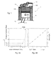
- Figure 1 at the end of the present description illustrates very schematically an example of configuration of a cylinder block 1 of a heat engine.
- the main components comprise a cylinder proper 11, a cylinder head 10 and a piston 12 in linear movement back and forth within the walls of the cylinder 11.
- the space between the upper wall of the piston 12 and the lower wall of the cylinder head 10 defines the combustion chamber 13, a place of intense heating due to the combustion of the gas mixture injected into this chamber. This results in significant heat transfer to the walls of the cylinder head 10, the cylinder 11 and to the piston 12.
- the four-stroke engines are provided with "water jackets", 100 and 110 respectively, the water circulating in enclosures created in the walls of the cylinder head 10 and the cylinder 11.
- T piston wall , T cylinder wall , T cylinder wall represent the respective temperatures (in ° C) of the walls of these components and S piston , S cylinder head , S cylinder , their surfaces (in m 2 ) exposure to the flow thermal.
- the combustion gas is the temperature of the gases (in ° C) during combustion, that is to say the temperature prevailing in the combustion chamber 13.
- the coefficient K is obtained by empirical correlations generally used during combustion analyzes for the calculation of heat flux.
- the correlation most often used is the so-called "Woschni” correlation which makes it possible to fix this coefficient K.
- heat fluxes are generally calculated using combustion analysis software which determines the temperatures of the combustion gases as well as the wall temperatures as functions of predetermined motor parameters (air mass, fuel mass, etc.)
- the parameters influencing the thermal flows are multiple.
- This relationship can be linear (which is usually true at full load), or higher.
- the absolute flows can be calculated in a given repository by using a combustion analysis tool, and the parameters of the previous linear relation identified.
- the different input parameters above can be system data (calculator instructions for the fuel mass, the injection advance, etc.).
- the object of the invention is to provide a method of estimating determined physical parameters, characteristic of the operation of a heat engine, and of controlling the thermal flows to which the components of this heat engine are subjected, aiming at overcoming the disadvantages of the processes and devices of the known art, some of which have just been recalled
- the estimation of determined physical parameters associated with an engine thermal is performed in real time, in particular with regard to the fuel flow, the air flow, the combustion phase, etc., as a function of the cylinder pressure, the associated thermal flows as a function of identified constants being calculated during the development of this engine, that is to say during a preliminary or initial phase, for example experimentally.
- the temperature of the injected air + EGR mixture can be measured or estimated by a predetermined specific model. If the "measurement” option is selected, this measurement can be done in the intake manifold for example, taking into account the "EGR" mentioned above.
- the estimation of the parameters and the flow control having the characteristics recalled above can be obtained by measuring the pressure prevailing in all or some of the cylinders, and by adopting a control strategy, using this cylinder pressure parameter, which will be specified. and detailed below.
- Such a measurement can be made simply by using one or more standard pressure sensor implanted in one or more rolls. Current motors of such sensors are already present, and the pressure measurement necessary to perform the control step according to the invention does not entail a significant additional cost and complexity.
- the invention thus has many advantages, in particular the method of the invention makes it possible to reduce the development margins during the development of the engines with respect to the thermal flows, and to control the flow levels during critical life situations. for the motor components. It allows a good behavior over time of these components.
- FIG. 2 very schematically illustrates such a configuration. Only the essential organs necessary for a good understanding of the invention have been represented.
- the motor 3 includes an engine block 30 itself comprising, in the example of Figure 2, four cylinders 1a to 1d, similar to the cylinder 1 already described with reference to Figure 1.
- an engine inlet block 30 fresh air is fed to the cylinders, 1a to 1d, via an intake duct 310, to an inlet manifold 31 and the individual conduits 311. at the output of the engine block 30, the exhaust gas is expelled by an exhaust line 300.
- a stitching member of the EGR consists of a valve 33 for diverting to the inlet distributor 31 via a conduit 330, a variable percentage of the exhaust gas. It therefore turns out that, in fact, the intake distributor 31 delivers an air / exhaust mixture at the inlet of the engine 3by the intake duct 310.
- one or more pressure sensors 34 for measuring the pressure in the combustion chambers of the cylinders 1 a to 1 d, at least one sensor being necessary in the specific context of the invention .
- This or these sensors 34 may be integrated in the cylinder head or in the glow plugs.
- the sensors 34 measure the pressure in the combustion chamber of all or part of the cylinders 1a through 1d.
- the output signals of sensors 34 are transmitted to an electronic control unit or "ECU” (for "Electronic Control Unit” according to the English terminology commonly used).
- a temperature sensor 35 is also provided on the intake distributor 31. The measured signals are also transmitted to the computer 32.
- the motor 3 also comprises a body 40 comprising a common supply rail (not shown) adapted to feed the engine cylinders, 1a to 1d, in multiple injections of fuel such as a pilot injection followed by a main injection.
- a common supply rail not shown
- the output signals of these devices are transmitted to the computer 32.
- the computer 32 According to these signals and other standard signals, the computer 32 generates control signals, in a conventional manner per se, and transmits control signals making it possible to drive specific members of the motor 3 (injectors not shown, valve 33, member 40, etc.), especially those necessary for carrying out the process of the invention.
- the computer 32 is particularly suitable for controlling the fuel injection parameters in each cylinder, in particular the feed angle, the flow rate and the duration of the fuel injection into the cylinder, as is known per se. in the state of the art.
- the piloting of the fuel injection is carried out from a first predetermined law for controlling the injection of fuel into the cylinders, 1 a to 1 d , and a second predetermined law for controlling the fuel injection. intake of the air / exhaust mixture at the inlet 31/310 of the engine 3.
- the computer 32 is arranged to correct the first control law of the injection in order to obtain throughout the life of the vehicle nominal emission levels of pollutants and combustion noise despite the presence of drifts in the operation in the motor and fast transients of it.
- the motor 3 comprises a body 38 comprising computing means 380 receiving the output signals or sensor (s) 34 measuring the pressure in at least one of the engine cylinders, 1a to 1d, and the crank angle acquisition member 36.
- These calculation means 380 are adapted to determine, as a function of the acquired pressures and angles, a quantity relative to the phasing of the combustion of the fuel in each cylinder, 1 a to 1 d , and for each cycle of this cylinder.
- These calculation means 380 also make it possible to determine the release of heat caused by the combustion of the fuel injected into the cylinder for the current cycle from relations which will be explained below.
- the member 38 further comprises calculation means 381 which receive the output signals of the calculation means 380 and are adapted to the calculation, as a function of the release of heat delivered by the calculation means 380, a crankshaft angle CAx corresponding to a predetermined fraction X of the total amount of fuel burned in the cylinder for the current cycle, as will be detailed hereinafter in the description of the process.
- the motor 3 also comprises means 39 which receive the output signals of the calculation means 381 and are adapted to correct the control of the injection as a function of the crankshaft angle CAx determined.
- These means 39 comprise in particular mapping means (not shown) which receive the output signals from the operating acquisition device 37 of the engine 3 and which are arranged to deliver, as a function of the operating point acquired from the engine 3, an instruction for the crankshaft angle CAx from a predetermined mapping of angles.
- the method according to the invention comprises two main phases: a phase of estimation of determined physical parameters characteristic of the operation of a heat engine and a phase of control of heat flows. on specific components of this engine, including the cylinder or cylinders, the cylinder head and the piston of each cylinder.
- the first phase may be preceded by an initial or preliminary phase performed at the time of engine design, the first and second phases comprising taking place in real time.
- the engine comprises four cylinders, it being understood that this number can be any (1, 4 or 6 cylinders, for example). It will also be assumed that this is a diesel engine, it being understood that the process according to the invention applies equally to gasoline engines and diesel engines, as has been recalled. To fix ideas, we will refer again, in what follows, to the configuration described with reference to Figure 2.
- the first step consists in calculating the fuel mass injected from the cylinder pressure signal.
- the determination of the quantity of fuel injected during the so-called main injection, and therefore of the fuel mass can be carried out by evaluating the average heat clearance DQ over an interval centered with respect to this injection.
- the heat evolution measurements are obtained from measurements of the pressure prevailing in the combustion chamber of a cylinder, 1a to 1d, for example by means of one or more sensor (s) 34 integrated pressure (s) in the cylinder head or in the glow plug of a diesel engine.
- the second step consists in calculating the mass of air entering the cylinders, 1 a to 1 d , via the intake duct 310, again from the cylinder pressure signal.
- the estimate of the air mass entering the cylinders, 1 a to 1 d, is based on a polytropic model.
- FIGS. 3A and 3B illustrate, in the form of two graphs, a pressure profile in a given combustion chamber (for example FIG. 1:13) measured during the compression phase (FIG. 3A) and FIG. linear relationship between the total gas flow rate and the sum of pressure variations in the combustion chamber considered according to the angular positions of the crankshaft (for example Figure 1: 12).
- the ordinate axis of the graph of FIG. 3A represents the cylinder pressure in bars (10 5 Pa) and the abscissa axis the crankshaft angle (° VII).
- the ordinate axis of the graph of FIG. 3B represents the total flow (in Kg) and the abscissa axis the sum of pressure variations also in bars.
- the graph of FIG. 3B clearly shows a linear relationship linking the flow rate to ⁇ P i , with i : 1 to n.
- the coefficient A ' is corrected as a function of the temperature of the intake air which can be measured by the sensor 35 positioned in the above-mentioned distributor 31.
- This estimate which requires the presence of at least one pressure sensor 34 in one of the rolls, 1 a to 1 d, is based on a linear relationship linking the flow rate as has been shown with reference to FIGS. 3A and 3B.
- the difficulty of evaluating the regression slope (coefficient A ') lies in its dependence on the temperature of the gases in a cylinder (for a chosen reference angle), which itself strongly depends on the variations of the EGR rate. in a diesel engine.
- AT AT 0 T charge relation in which A 0 is a constant calibrated according to tests carried out in the design phase specific to each engine configuration (initial phase mentioned above) and T air + EGR mixture the temperature in the intake manifold after mixing air and fuel. EGR.
- the third step is the calculation of the combustion phasing.
- the combustion phase corresponds to the crankshaft angle for which X% of fuel has been burned (with X between 0 and 100).
- the phasing CA x corresponds to the angle at which the BKW normalized by the total mass burned (integration over the entire combustion cycle) equals X %
- the fourth step consists of measuring the temperature of the air + EGR malfunction at the engine inlet.
- the temperature of the air + EGR mixture can be measured using a temperature sensor 35 positioned in the inlet distributor 31 downstream of the EGR quilting. .
- this temperature can also be modeled or mapped as a function of the operating point of this engine (initial phase mentioned above). In the latter case, this mapping can, as before, be recorded in memory means usually associated with the computer 32.
- the control of the thermal flows is based on the estimation of the aforementioned thermal flows, the estimation being a function of the four physical parameters acquired or measured during the stages of the first phase and characteristics of a given heat engine, namely the mass or the air flow, mass or fuel flow, combustion phasing and charge temperature.
- the method according to the invention makes it possible, according to a flow setpoint mapping for each operating point of the engine, to control the closed-loop, real-time and cycle-to-cycle flux levels, also using one or more cylinder pressure sensors 34.
- mapping is determined during the initial tuning of a given engine 3 (initial phase mentioned above).
- the "fuel quantity" actuator can not be used, since the partial load operation is set by the amount of fuel.
- an action on the ignition advance, the air flow and / or the temperature can be used to control the heat flow.
- the instructions can be adapted by changing the injection time in the case of a diesel engine or the ignition advance in the case of a gasoline engine.
- the set points can be adapted by changing the air boost pressure the position of the throttle valve. EGR valve 33, that is the fraction of the recycled exhaust gas. It is understood again that "air” "[air + EGR].
- combustion phasing it is possible to adapt the setpoints by modifying the fuel injection advance (diesel engine) or the ignition advance (gasoline engine).
- the decrease in heat flow on a piston can be achieved by reducing the amount of fuel and a "sub-calibration of the injection". Such operation is obtained by a later combustion, itself obtained by a delayed injection into the combustion cycle.
- the controlled heat flow is here the heat flow on each piston (for example Figure 1: 12) and the actuator is, for example, the amount of fuel, hereinafter referred to as Qcarb .
- the regulator is a regulator of type known as "PID" (for proportional action - integral - derivative) classic used generically for the control of the engines.
- Offset corresponds to the pitch of the variation of the quantity of fuel necessary to modify the thermal flows.
- this step is typically of the order 0.2 mg per shot. This quantity is determined during an initial phase of development depending on the engine and the sensitivities of the heat flows to this parameter.
- block 20 calculates heat flow to the piston (for example, FIG. 1: 12). It receives the results of the calculations made by the blocks 26 and 27 described below (links 260 and 270).
- the output of the block 27 is looped back, as previously indicated (link 270) on the heat flow calculation block 20 to the piston.
- the method according to the invention makes it possible to directly control, in a closed loop and in real time, the heat flux levels applied to the components of the engine.
- the invention applies equally to a diesel engine or a gasoline engine.
Abstract
Description
L'invention concerne un procédé d'estimation des paramètres caractérisant le fonctionnement d'un moteur thermique et de contrôle des flux thermiques appliqués à des composants de ce moteur.The invention relates to a method for estimating the parameters characterizing the operation of a heat engine and controlling heat flows applied to components of this engine.
Il concerne la tenue thermique des composants d'un tel moteur directement soumis aux flux de combustion. Ces composants sont notamment le piston, la culasse et le cylindreIt relates to the thermal resistance of the components of such an engine directly subjected to combustion flows. These components include piston, cylinder head and cylinder
Plus particulièrement, le procédé selon l'invention permet de contrôler directement, en boucle fermée et en temps réel, les niveaux de flux thermiques appliqués à ces composants de moteur.More particularly, the method according to the invention makes it possible to directly control, in a closed loop and in real time, the thermal flux levels applied to these motor components.
Dans le cadre de l'invention, le terme "moteur" s'applique indifféremment à tous types de moteurs thermiques, qu'ils soient de type à essence ou diesel. Pour simplifier, dans ce qui suit, le terme générique "moteur" sera donc utilisé.In the context of the invention, the term "engine" applies equally to all types of combustion engines, whether of gasoline or diesel type. For simplicity, in what follows, the generic term "engine" will be used.
Il est tout d'abord utile de rappeler les principales données caractérisant la génération des flux thermiques issus de la combustion.First of all, it is useful to recall the main data characterizing the generation of heat flows from combustion.
La figure 1 placée en fin de la présente description illustre très schématiquement un exemple de configuration d'un bloc cylindre 1 d'un moteur thermique. Les composants principaux comprennent un cylindre proprement dit 11, une culasse 10 et un piston 12 en mouvement linéaire de va et vient à l'intérieur des parois du cylindre 11. L'espace compris entre la paroi supérieure du piston 12 et la paroi inférieure de la culasse 10 définit la chambre de combustion 13, lieu d'un échauffement intense dû à la combustion du mélange de gaz injecté dans cette chambre. Il en résulte des transferts thermiques importants vers les parois de la culasse 10, du cylindre 11 et vers le piston 12. Pour limiter l'échauffement de ces composants, on prévoit dans les moteurs quatre temps des "chemises d'eau", 100 et 110 respectivement, l'eau circulant dans des enceintes créées dans les parois de la culasse 10 et du cylindre 11.Figure 1 at the end of the present description illustrates very schematically an example of configuration of a
Comme il est bien connu, les flux thermiques sur les différents composants du moteur, à savoir le piston 12, la culasse 10 et le cylindre 11, exprimés en Watts, obéissent aux relations suivantes : ![]()
![]()
![]()
![]()
![]()
![]()
Le coefficient K est obtenu par des corrélations empiriques généralement utilisées lors d'analyses de combustion pour le calcul de flux thermique. La corrélation la plus souvent utilisée est la corrélation dite de "Woschni" qui permet de fixer ce coefficient K. The coefficient K is obtained by empirical correlations generally used during combustion analyzes for the calculation of heat flux. The correlation most often used is the so-called "Woschni" correlation which makes it possible to fix this coefficient K.
De façon connue également, les flux thermiques sont généralement calculés à l'aide d'un logiciel d'analyse de combustion qui détermine les températures des gaz de combustion ainsi que les températures de parois en fonctions de paramètres moteurs prédéterminés (masse d'air, masse de carburant, etc.)In a manner also known, heat fluxes are generally calculated using combustion analysis software which determines the temperatures of the combustion gases as well as the wall temperatures as functions of predetermined motor parameters (air mass, fuel mass, etc.)
Il est donc possible de cartographier les flux thermiques en fonction du point de fonctionnement d'un moteur donné (régime / couple), lors de la phase de mise au point de ce moteur.It is therefore possible to map the thermal flows according to the operating point of a given engine (speed / torque), during the development phase of this engine.
Les paramètres influençant les flux thermiques sont multiples.The parameters influencing the thermal flows are multiple.
Comme il vient d'être rappelé, les flux thermiques sont fonction du point de fonctionnement moteur. Il est donc possible de les estimer et de les identifier en fonction des paramètres moteurs principaux suivants:
- la masse ou le débit de carburant injecté ;
- la masse ou le débit d'air utilisé;
- la température du mélange air + EGR (air + "EGR", pour "Exhaust Gas Recirculation", ou recyclage des gaz d'échappement) en entrée du moteur ; et
- l'angle de début d'injection ou d'allumage pour les moteurs à essence, qui se traduit fonctionnellement par une valeur dite de "phasage de combustion" dans le cycle (début de combustion ou angle correspondant à x % de carburant brûlé).
- the mass or flow of fuel injected;
- the mass or flow of air used;
- the temperature of the air + EGR mixture (air + "EGR", for "Exhaust Gas Recirculation", or exhaust gas recirculation) at the engine inlet; and
- the injection or ignition start angle for gasoline engines, which is functionally translated into a so-called "combustion phase" value in the cycle (start of combustion or angle corresponding to x% of fuel burned).
Le flux sur chaque composant du moteur, piston 12, culasse 10 et cylindre 11, obéit alors à la relation suivante (4), relation dans laquelle f() est une fonction de plusieurs paramètres et Tmélange air + EGR la température de l'air injecté : 
Cette relation peut être linéaire (ce qui est généralement vrai à pleine charge), ou bien de degré supérieur.This relationship can be linear (which is usually true at full load), or higher.
Pour une relation linéaire, l'expression précédente prend la forme suivante : 
Lors du développement d'un moteur, les flux absolus peuvent dont être calculés dans un référentiel donné en faisant appel à un outil d'analyse de combustion, et les paramètres de la relation linéaire précédente identifiés.During the development of an engine, the absolute flows can be calculated in a given repository by using a combustion analysis tool, and the parameters of the previous linear relation identified.
De façon pratique, pour chaque point de charge, on associe donc un flux thermique à différentes valeurs des paramètres "masse carburant", "masse d'air", "température du mélange air + EGR admis", etc.In practical terms, for each point of charge, a thermal flux is therefore associated with different values of the parameters "fuel mass", "air mass", "air mixture temperature + EGR admitted", etc.
Les différents paramètres d'entrée précédents peuvent être des données systèmes (consignes calculateur pour la masse de carburant, l'avance à l'injection, etc.).The different input parameters above can be system data (calculator instructions for the fuel mass, the injection advance, etc.).
Cependant, les procédés mis en oeuvre dans l'art connu pour estimer les flux thermiques présentent plusieurs inconvénients.However, the methods used in the known art for estimating heat fluxes have several drawbacks.
Notamment, le désavantage principal rencontré lorsque l'on utilise ces données d'entrée provient du fait que les paramètres systèmes ne reflètent pas les valeurs réelles.In particular, the main disadvantage encountered when using this input data is that the system parameters do not reflect the actual values.
En particulier, il est bien connu que les injecteurs de carburant présentent des dispersions quant à leurs caractéristiques de fonctionnement, même lorsqu'ils sont neufs, et dérivent dans le temps, avec des amplitudes de dérives de valeurs non négligeables. Il s'ensuit que les quantités réelles de carburant injecté correspondent en réalité à des valeurs différentes des quantités systèmes demandées.In particular, it is well known that fuel injectors have dispersions with regard to their operating characteristics, even when they are new, and drift over time, with drift amplitudes of significant values. It follows that the actual quantities of fuel injected actually correspond to different values of the required system quantities.
Un phénomène analogue est constaté en ce qui concerne le débit d'air, conséquence des dispersions et dérives des composants de la boucle d'air (turbocompresseur, débitmètre d'air, etc.), d'un capteur de température, ou du capteur régime (pour la détermination du début d'injection ou d'allumage),A similar phenomenon is observed with regard to the air flow, as a consequence of the dispersions and drifts of the components of the air loop (turbocharger, air flow meter, etc.), of a temperature sensor, or of the sensor regime (for determining the start of injection or ignition),
Pour pallier ces dysfonctionnements, il est d'usage, dans l'art connu, d'adopter des marges de développement importantes pour éviter tout risque destruction du moteur après dispersions et dérives des composants d'ordre 1 pour les flux thermiques. Cela conduit le plus souvent à des augmentations du coût, en tout état de cause à des fonctionnements opérationnels manquant de précision.To overcome these malfunctions, it is customary in the known art to adopt significant development margins to avoid any risk of destruction of the engine after dispersions and drifts of the first-order components for heat flows. This leads most often to cost increases, in any case to operational operations lacking precision.
L'invention se fixe pour but un procédé d'estimation de paramètres physiques déterminés, caractéristiques du fonctionnement d'un moteur thermique, et de contrôle des flux thermiques auxquels sont soumis les composants de ce moteur thermique, visant à pallier les inconvénients des procédés et dispositifs de l'art connu, dont certains viennent d'être rappelésThe object of the invention is to provide a method of estimating determined physical parameters, characteristic of the operation of a heat engine, and of controlling the thermal flows to which the components of this heat engine are subjected, aiming at overcoming the disadvantages of the processes and devices of the known art, some of which have just been recalled
Le procédé selon l'invention comprend deux phases principales :
- une phase d'estimation de paramètres physiques déterminés, caractéristiques du fonctionnement d'un moteur thermique ;
- et une phase de contrôle des flux thermiques sur des composants déterminés de ce moteur, notamment le ou les cylindres, la culasse et le piston de chaque cylindre;
- a phase of estimation of determined physical parameters characteristic of the operation of a heat engine;
- and a heat flow control phase on specific components of this engine, including the cylinder or cylinders, the cylinder head and the piston of each cylinder;
Selon une première caractéristique importante de l'invention, l'estimation de paramètres physiques déterminés associés à un moteur thermique s'effectue en temps réel, notamment en ce qui concerne le débit de carburant, le débit d'air, le phasage de combustion, etc., en fonction de la pression cylindre, les flux thermiques associés en fonction de constantes identifiées étant calculés lors de la mise au point de ce moteur, c'est-à-dire lors d'une phase préliminaire ou initiale, par exemple de façon expérimentale.According to a first important characteristic of the invention, the estimation of determined physical parameters associated with an engine thermal is performed in real time, in particular with regard to the fuel flow, the air flow, the combustion phase, etc., as a function of the cylinder pressure, the associated thermal flows as a function of identified constants being calculated during the development of this engine, that is to say during a preliminary or initial phase, for example experimentally.
On peut noter dès à présent que la température du mélange air + EGR injecté peut être mesurée ou estimée par un modèle spécifique préétabli. Si l'option "mesure" est retenue, cette mesure peut être effectuées dans le répartiteur d'admission par exemple, avec prise en compte de l' "EGR" précité.It can be noted as of now that the temperature of the injected air + EGR mixture can be measured or estimated by a predetermined specific model. If the "measurement" option is selected, this measurement can be done in the intake manifold for example, taking into account the "EGR" mentioned above.
Selon une deuxième caractéristique importante de l'invention, contrairement aux procédés de l'art connu, il est procédé à un contrôle direct, en boucle fermée et en temps réel, des niveaux de flux thermiques appliqués aux composants du moteur.According to a second important characteristic of the invention, unlike the methods of the prior art, a direct, closed-loop and real-time control of the thermal flux levels applied to the engine components is carried out.
L'estimation des paramètres et le contrôle de flux présentant les caractéristiques rappelées ci-dessus peuvent être obtenus en mesurant la pression régnant dans tout ou partie des cylindres, et en adoptant une stratégie de contrôle, utilisant ce paramètre de pression cylindre, qui sera précisée et détaillée ci-après.The estimation of the parameters and the flow control having the characteristics recalled above can be obtained by measuring the pressure prevailing in all or some of the cylinders, and by adopting a control strategy, using this cylinder pressure parameter, which will be specified. and detailed below.
Une telle mesure peut être réalisée simplement en faisant appel à un ou plusieurs capteur de pression standard implanté(s) dans un ou plusieurs cylindre(s). Sur les moteurs actuels de tels capteurs sont déjà présents, et la mesure de pression nécessaire pour réaliser l'étape de contrôle selon l'invention n'entraîne pas un supplément significatif de coût et de complexité.Such a measurement can be made simply by using one or more standard pressure sensor implanted in one or more rolls. Current motors of such sensors are already present, and the pressure measurement necessary to perform the control step according to the invention does not entail a significant additional cost and complexity.
L'invention présente donc de nombreux avantages, notamment le procédé de l'invention permet de réduire les marges de développement lors de la mise au point des moteurs au regard des flux thermique, et de contrôler les niveaux de flux lors de situations de vie critiques pour les composants moteurs. Il permet une bonne tenue dans le temps de ces composants.The invention thus has many advantages, in particular the method of the invention makes it possible to reduce the development margins during the development of the engines with respect to the thermal flows, and to control the flow levels during critical life situations. for the motor components. It allows a good behavior over time of these components.
L'invention a donc pour objet principal un procédé d'estimation de paramètres déterminés caractérisant le fonctionnement d'un moteur thermique comprenant au moins un cylindre et de contrôle des flux thermiques appliqués à des composants du moteur thermique, le moteur thermique comprenant des moyens pour réinjecter en entrée un pourcentage déterminé de la masse des gaz d'échappement éjectés pour réaliser un recyclage de ces gaz dit "EGR", caractérisé en ce qu'il comprend, au moins,
- un première phase consistant en l'estimation des paramètres déterminés, ces paramètres étant la valeur de la masse de carburant injecté dans la chambre de combustion de chacun des cylindres, la valeur de la masse du mélange air+ EGR en entrée du moteur thermique, la température du mélange et une grandeur dite de "phasage de combustion" dans un cycle de combustion ; et
- une deuxième phase consistant dans le contrôle en boucle fermée et en temps réel du flux thermique appliqué à au moins un des composants du moteur thermique, à partir d'une grandeur dérivée d'au moins un des paramètres caractéristiques estimés, dite "actionneur"
- a first phase consisting in estimating the determined parameters, these parameters being the value of the mass of fuel injected into the combustion chamber of each of the cylinders, the value of the mass of the air + EGR mixture at the inlet of the engine, the temperature mixture and a so-called "combustion phasing" quantity in a combustion cycle; and
- a second phase consisting in the closed-loop control and in real time of the heat flux applied to at least one of the components of the heat engine, from a quantity derived from at least one of the estimated characteristic parameters, called "actuator"
L'invention va maintenant être décrite de façon plus détaillée en se référant aux dessins annexés, parmi lesquels :
- la figure 1 illustre schématiquement un exemple de configuration d'un bloc cylindre montrant les principaux composants exposés aux flux thermique dus à la combustion des gaz ;
- la figure 2 illustre schématiquement un exemple de configuration de moteur thermique et d'un dispositif associé pour la mise en oeuvre du procédé selon un mode de réalisation préféré de l'invention;
- les figures 3A et 3B sont des graphes illustrant un profil de pression dans une chambre de combustion mesuré pendant la phase de compression et la relation linéaire liant le débit total de gaz et la somme de variations de pression dans cette chambre de combustion ; et
- la figure 4 illustre schématiquement, à titre d'exemple, le contrôle du flux thermique sur un piston en pleine charge
- Figure 1 schematically illustrates an example configuration of a cylinder block showing the main components exposed to heat flow due to the combustion of gases;
- FIG. 2 schematically illustrates an example of a thermal engine configuration and of an associated device for implementing the method according to a preferred embodiment of the invention;
- FIGS. 3A and 3B are graphs illustrating a pressure profile in a combustion chamber measured during the compression phase and the linear relationship linking the total gas flow rate and the sum of pressure variations in this combustion chamber; and
- FIG. 4 schematically illustrates, by way of example, the control of the heat flow on a fully loaded piston.
On va tout d'abord décrire la configuration d'un moteur et d'un dispositif permettant l'implémentation du procédé selon l'invention.We will first describe the configuration of a motor and a device for implementing the method according to the invention.
La figure 2 illustre très schématiquement une telle configuration. Seuls les organes essentiels nécessaires à la bonne compréhension de l'invention ont été représentés.Figure 2 very schematically illustrates such a configuration. Only the essential organs necessary for a good understanding of the invention have been represented.
Le moteur 3 comprend un bloc moteur proprement dit 30 comportant, dans l'exemple de la figure 2, quatre cylindres, 1a à 1d, similaires au cylindre 1 déjà décrit en regard de la figure 1. En entrée du bloc moteur 30, l'air frais est transmis aux cylindres, 1a à 1d, via un conduit d'admission 310, à un répartiteur d'admission 31 et des conduits individuels 311. En sortie du bloc moteur 30, le gaz d'échappement est expulsé par une ligne d'échappement 300.The
Outre divers organes classiques (pot d'échappement, etc., non représentés), on dispose sur cette ligne d'échappement 300 un organe de piquage de l'EGR constitué d'une vanne 33 destinée à dériver vers le répartiteur d'admission 31, via un conduit 330, un pourcentage variable des gaz d'échappement. Il s'avère donc, qu'en réalité, le répartiteur d'admission 31 délivre un mélange air/gaz d'échappement en entrée du moteur 3parle conduit d'admission 310.In addition to various conventional members (muffler, etc., not shown), there is disposed on this exhaust line 300 a stitching member of the EGR consists of a
Selon une caractéristique importante de invention, on prévoit un ou plusieurs capteurs de pression 34 pour mesurer la pression régnant dans les chambres de combustion des cylindres, 1a à 1 d, au moins un capteur étant nécessaire dans le cadre plus particulier de l'invention. Ce ou ces capteurs 34 peuvent être intégrés dans la culasse des cylindres ou dans les bougies de préchauffage. Les capteurs 34 mesurent la pression régnant dans la chambre de combustion de tout ou partie des cylindres 1a à 1d. Les signaux de sortie de des capteurs 34 sont transmis à une unité de contrôle électronique ou "ECU" (pour "Electronic Control Unit" selon la terminologie anglo-saxonne couramment utilisée).According to an important characteristic of invention there is provided one or
Il peut s'agir avantageusement d'un calculateur numérique à programme enregistré. De tels calculateurs sont généralement présents sur les moteurs récents, ce qui n'entraîne donc pas de coût supplémentaire significatif. Les modifications nécessaires se résument essentiellement à une adaptation des programmes résidents et/ou l'ajout de modules logiciels spécifiques au procédé de l'invention.It may advantageously be a digital computer with a registered program. Such calculators are generally present on recent engines, which does not entail significant additional cost. The necessary modifications essentially boil down to an adaptation of the resident programs and / or the addition of software modules specific to the method of the invention.
On prévoit également un capteur de température 35 disposé sur le répartiteur d'admission 31. Les signaux mesurés sont également transmis au calculateur 32.A
Le moteur 3 comprend également un organe 40 comportant une rampe commune d'alimentation (non représentée) adapté pour alimenter les cylindres du moteur, 1a à 1d, selon des injections multiples de carburant, comme par exemple une injection pilote suivie d'une injection principale.The
On prévoit également des moyens 36 d'acquisition de l'angle vilebrequin de chaque cylindre et des moyens 37 d'acquisition du point de fonctionnement du moteur, notamment le régime de rotation du moteur, le couple moteur demandé par le conducteur et la pression dans la rampe commune d'alimentation.Provision is also made for
Les signaux de sortie de ces organes (capteur de température 35, capteur(s) de pression 34, moyens d'acquisition d'angle vilebrequin 36 et de point de fonctionnement 37) sont transmis au calculateur 32.The output signals of these devices (
En fonction de ces signaux et d'autres signaux standards, le calculateur 32 élabore des signaux de commande, de façon classique en soi, et transmet des signaux de commande permettant de piloter des organes déterminés du moteur 3 (injecteurs non représentés, vanne 33, organe 40, etc.), notamment ceux nécessaires à la mise en oeuvre du procédé de l'invention.According to these signals and other standard signals, the
Le calculateur 32 est notamment adapté pour piloter les paramètres de l'injection de carburant dans chaque cylindre, en particulier l'angle d'avance, le débit et la durée de l'injection de carburant dans le cylindre, comme cela est connu en soi dans l'état de la technique.The
Plus spécifiquement, le pilotage de l'injection de carburant est réalisé à partir d'une première loi prédéterminée de pilotage de l'injection de carburant dans les cylindres, 1a à 1d, et d'une seconde loi prédéterminée de pilotage de l'admission du mélange air/gaz d'échappement en entrée 31/310 du moteur 3.More specifically, the piloting of the fuel injection is carried out from a first predetermined law for controlling the injection of fuel into the cylinders, 1 a to 1 d , and a second predetermined law for controlling the fuel injection. intake of the air / exhaust mixture at the
Le calculateur 32 est agencé pour corriger la première loi de pilotage de l'injection afin d'obtenir tout au long de la vie du véhicule des niveaux nominaux d'émission de polluants et de bruit de combustion malgré la présence de dérives dans le fonctionnement dans le moteur et de transitoires rapides de celui-ci.The
Pour ce faire, le moteur 3 comprend un organe 38 comprenant des moyens de calcul 380 recevant les signaux de sortie du ou des capteur(s) 34 mesurant la pression dans au moins un des cylindres du moteur, 1a à 1 d, et de l'organe d'acquisition de l'angle vilebrequin 36. Ces moyens de calcul 380 sont adaptés pour déterminer en fonction des pressions et des angles acquis une grandeur relative au phasage de la combustion du carburant dans chaque cylindre, 1a à 1d, et pour chaque cycle de ce cylindre. Ces moyens de calcul 380 permettent également de déterminer le dégagement de chaleur provoqué par la combustion du carburant injecté dans le cylindre pour le cycle courant à partir de relations qui seront explicitées ci-après.To do this, the
L'organe 38 comprend en outre des moyens de calcul 381 qui reçoivent les signaux de sortie des moyens de calcul 380 et sont adaptés au calcul, en fonction du dégagement de chaleur délivré par les moyens de calcul 380, un angle vilebrequin CAx correspondant à une fraction prédéterminée X de la quantité totale de carburant brûlé dans le cylindre pour le cycle courant, de la manière qui sera détaillée ci-après lors de la description du procédé.The
Le moteur 3 comprend également des moyens 39 qui reçoivent les signaux de sortie des moyens de calcul 381 et sont adaptés pour corriger le pilotage de l'injection en fonction de l'angle vilebrequin CAx déterminé. Ces moyens 39 comprennent notamment des moyens formant cartographie (non représentés) qui reçoivent les signaux de sortie de l'organe 37 d'acquisition de fonctionnement du moteur 3 et qui sont agencés pour délivrer, en fonction du point de fonctionnement acquis du moteur 3, une consigne pour l'angle vilebrequin CAx à partir d'une cartographie prédéterminée d'angles.The
On va maintenant décrire le procédé de l'invention.The method of the invention will now be described.
Comme il a été rappelé dans le préambule de la présente description, le procédé selon l'invention comprend deux phases principales : une phase d'estimation de paramètres physiques déterminés, caractéristiques du fonctionnement d'un moteur thermique et une phase de contrôle des flux thermiques sur des composants déterminé de ce moteur, notamment la ou les cylindres, la culasse et le piston de chaque cylindre.As has been pointed out in the preamble of the present description, the method according to the invention comprises two main phases: a phase of estimation of determined physical parameters characteristic of the operation of a heat engine and a phase of control of heat flows. on specific components of this engine, including the cylinder or cylinders, the cylinder head and the piston of each cylinder.
Comme il sera précisé ci-après, la première phase peut être précédée d'une phase initiale ou préliminaire réalisée au moment de la conception du moteur, les première et deuxième phases comprenant se déroulant en temps réel.As will be specified below, the first phase may be preceded by an initial or preliminary phase performed at the time of engine design, the first and second phases comprising taking place in real time.
On va maintenant détailler la première phase et les principales étapes qu'elle comporte pour estimer des paramètres physiques déterminés caractéristiques du fonctionnement d'un moteur donné.We will now detail the first phase and the main steps involved in estimating specific physical parameters characteristic of the operation of a given engine.
Pour fixer les idées, on supposera dans ce qui suit que le moteur comprend quatre cylindre, étant entendu que ce nombre peut être quelconque (1, 4 ou 6 cylindres, par exemple). On supposera également qu'il s'agit d'un moteur diesel, étant entendu que le procédé selon l'invention s'applique indifféremment aux moteurs à essence et aux moteurs diesel, comme il a été rappelé. Pour fixer les idées, on se référera donc de nouveau, dans ce qui suit, à la configuration décrite en regard de la figure 2.To fix ideas, it will be assumed in the following that the engine comprises four cylinders, it being understood that this number can be any (1, 4 or 6 cylinders, for example). It will also be assumed that this is a diesel engine, it being understood that the process according to the invention applies equally to gasoline engines and diesel engines, as has been recalled. To fix ideas, we will refer again, in what follows, to the configuration described with reference to Figure 2.
Les principales étapes nécessaires pour obtenir une estimation de paramètres physiques caractérisant le fonctionnement d'un moteur donné sont les suivantes :
- calcul de la masse de carburant injecté dans les cylindres
- calcul de la masse d'air entrant dans les cylindres ;
- calcul du phasage de combustion ; et
- mesure de la température du mélange air + EGR en entrée du moteur.
- calculation of the mass of fuel injected into the cylinders
- calculation of the air mass entering the cylinders;
- calculation of the combustion phase; and
- measurement of the air + EGR mixture temperature at the engine inlet.
Ces étapes vont maintenant être détaillées.These steps will now be detailed.
La première étape consiste dans le calcul de la masse de carburant injecté à partir du signal de pression cylindre.The first step consists in calculating the fuel mass injected from the cylinder pressure signal.
Le calcul de la masse de carburant peut être réalisé selon le procédé décrit dans le brevet
Dans ce brevet, on a démontré qu'il est possible, en mesurant la pression régnant dans la chambre de combustion d'un cylindre, 1a à 1 d, de déterminer des dégagements de chaleur élémentaire à un instant donné.In this patent, it was demonstrated that it is possible, by measuring the pressure in the combustion chamber of a cylinder, 1a to 1d, to determine elemental exotherms at a given time.
A partir de ces données, la détermination de la quantité de carburant injectée lors de l'injection dite principale, et donc de la masse de carburant, peut être effectuée en évaluant le dégagement DQ de chaleur moyen sur un intervalle centré par rapport à cette injection principale,From these data, the determination of the quantity of fuel injected during the so-called main injection, and therefore of the fuel mass, can be carried out by evaluating the average heat clearance DQ over an interval centered with respect to this injection. main,
Les mesures de dégagement de chaleur sont obtenues à partir de mesures de la pression régnant dans la chambre de combustion d'un cylindre, 1a à 1d, par exemple au moyen d'un ou plusieurs capteur(s) de pression 34 intégré(s) dans la culasse ou dans la bougie de préchauffage d'un moteur diesel.The heat evolution measurements are obtained from measurements of the pressure prevailing in the combustion chamber of a cylinder, 1a to 1d, for example by means of one or more sensor (s) 34 integrated pressure (s) in the cylinder head or in the glow plug of a diesel engine.
Pour une description plus détaillée du procédé de calcul de la masse de carburant injecté à partir du signal de pression cylindre, on pourra se reporter avec profit au brevet
De façon plus précise, dans le cadre de la présente invention, le calcul de la masse de carburant injecté est basé sur le calcul d'un dégagement de chaleur simplifié obéissant à la relation ci-dessous : 
- dQ/dα est exprimé en Joules par ° ;
- P et V sont la pression et le volume dans le cylindre, respectivement;
- α est l'angle vilebrequin en °;
- k est le coefficient polytropique fixé à 1,34
- dQ / dα is expressed in Joules per °;
- P and V are the pressure and the volume in the cylinder, respectively;
- α is the crankshaft angle in °;
- k is the polytropic coefficient set at 1.34
La masse de carburant injecté est déduite par intégration du dégagement de chaleur sur la fenêtre de combustion et multiplication par le potentiel calorifique du carburant (PCI): ![]()
- mcarburant est la masse de carburant (en kg) ;
- dQ est exprimé en joules ; et
- PCI est exprimé kg/joules,
- m fuel is the mass of fuel (in kg);
- dQ is expressed in joules; and
- PCI is expressed kg / joules,
Une variante du calcul de la masse carburant est également décrite dans le brevet européen précité. Dans cette variante, on prend en compte une calibration de divers coefficients lors du développement du moteur: ![]()
![]()
La deuxième étape consiste dans le calcul de la masse d'air entrant dans les cylindres, 1a à 1d, via le conduit d'admission 310, toujours à partir du signal de pression cylindre.The second step consists in calculating the mass of air entering the cylinders, 1 a to 1 d , via the
Ce calcul peut être réalisé selon le procédé décrit dans les demandes de brevet, au nom de Peugeot Citroën Automobiles S.A.,
Dans de nombreux moteurs, on ajoute à l'air frais admis un pourcentage des gaz d'échappement du moteur qui sont recirculés vers l'entrée de la ou des chambres de combustion pour limiter les émissions de gaz toxiques. Ce pourcentage de gaz est appelé communément "EGR" (de l'anglo-saxon "Exaust Gaz recirculation"). De ce fait, par "masse d'air" on entend le paramètre [air frais + "EGR"]. Lorsque le moteur 3 comprend plusieurs cylindres, 1a à 1 d, on prévoit habituellement un répartiteur d'admission d'air (figure 2 : 31). Le pourcentage précité est obtenu en pilotant la vanne 33.In many engines, a percentage of the engine exhaust gases that are recirculated to the inlet of the combustion chamber or chambers is added to the fresh air admitted to limit the emissions of toxic gases. This percentage of gas is commonly called "EGR" (from the Anglo-Saxon "Exaust Gas Recirculation"). As a result, the term "air mass" means the parameter [fresh air + "EGR"]. When the
L'estimation de la masse d'air entrant dans les cylindres, 1 a à 1 d, se base sur un modèle polytropique.The estimate of the air mass entering the cylinders, 1 a to 1 d, is based on a polytropic model.
Pour une description plus détaillée du procédé de calcul de la masse de carburant injecté à partir du signal de pression cylindre, on pourra se reporter avec profit au brevet
Les figures 3A et 3B, annexées à la présente, illustrent, sous la forme de deux graphes, un profil de pression dans une chambre de combustion données (par exemple figure 1:13) mesuré pendant la phase de compression (figure 3A) et la relation linéaire liant le débit total de gaz et la somme de variations de pression dans la chambre de combustion considérée suivant les positions angulaires du vilebrequin (par exemple figure 1 : 12).FIGS. 3A and 3B, appended hereto, illustrate, in the form of two graphs, a pressure profile in a given combustion chamber (for example FIG. 1:13) measured during the compression phase (FIG. 3A) and FIG. linear relationship between the total gas flow rate and the sum of pressure variations in the combustion chamber considered according to the angular positions of the crankshaft (for example Figure 1: 12).
L'axe des ordonnées du graphe de la figure 3A représente la pression cylindre en bars (105 Pa) et l'axe des abscisses l'angle vilebrequin (°VII).The ordinate axis of the graph of FIG. 3A represents the cylinder pressure in bars (10 5 Pa) and the abscissa axis the crankshaft angle (° VII).
L'axe des ordonnées du graphe de la figure 3B représente le débit total (en Kg) et l'axe des abscisses la somme de variations de pression également en barsThe ordinate axis of the graph of FIG. 3B represents the total flow (in Kg) and the abscissa axis the sum of pressure variations also in bars.
Pour fixer les idées, on à représenté sur le graphe de la figure 3A différentes positions angulaires, α REF , α1, α2, ..., αn, pour des positions de mesure parmi n possibles. Ces positions sont comprises entre zéro et le "point mort haut" (PMH), avec αREF représentant la position angulaire de référence et ΔPi représentant les variations de pression par rapport à la pression mesurée pour αREF.To fix the ideas, it is represented on the graph of Figure 3A different angular positions, α REF , α 1 , α 2 , ..., α n , for measurement positions among n possible. These positions are between zero and the "top dead center" ( TDC ), with α REF representing the reference angular position and Δ P i representing the pressure variations with respect to the measured pressure for α REF .
On constate bien sur le graphe de la figure 3B une relation linéaire liant le débit à ΣΔPi , avec i: 1 à n. The graph of FIG. 3B clearly shows a linear relationship linking the flow rate to ΣΔP i , with i : 1 to n.
De façon plus précise, la masse d'air est estimée par une formule du type satisfaisant la relation suivante : ![]()
![]()
Le coefficient A' est corrigé en fonction de la température de l'air d'admission qui peut être mesuré par le capteur 35 positionné dans le répartiteur précité 31. Cette estimation, qui nécessite la présence d'au moins un capteur de pression 34 dans un des cylindres, 1a à 1 d, s'appuie sur une relation linéaire liant le débit comme il a été montré en regard des figures 3A et 3B. La difficulté de l'évaluation de la pente de régression (coefficient A') réside dans sa dépendance à la température des gaz dans un cylindre (pour un angle de référence choisi), qui elle-même dépend fortement des variations du taux d'EGR dans un moteur diesel. La relation suivante suivante est utilisée : 
La troisième étape consiste dans le calcul du phasage de combustion.The third step is the calculation of the combustion phasing.
Le calcul de phasage est effectué par les moyens de calcul 380 à partir du dégagement de chaleur, plus précisément le phasage est de nouveau calculé à partir du dégagement de chaleur simplifié suivant : 
- P est la pression dite de cylindre dans la chambre ;
- V est le volume de la chambre ;
- α est l'angle vilebrequin; et
- k est le coefficient polytropique fixé à 1,34.
- P is the so-called cylinder pressure in the chamber;
- V is the volume of the chamber;
- α is the crankshaft angle; and
- k is the polytropic coefficient set at 1.34.
Le phasage de combustion correspond à l'angle vilebrequin pour lequel X % de carburant a été brûlé (avec X compris entre 0 et 100).The combustion phase corresponds to the crankshaft angle for which X% of fuel has been burned (with X between 0 and 100).
Pour fixer les idées, à titre d'exemple, il est traditionnellement utilisé les phasages CAx suivants:
- CA5 (Angle pour lequel 5% de carburant a été brûlé- représentatif de l'angle de début de combustion);
- CA 25 (Angle pour lequel 25% de carburant a été brûlé) ;
- CA 50 (Angle pour lequel 50% de carburant a été brûlé) ;
- CA75 (Angle pour lequel 75% de carburant a été brûlé) ; et
- CA90 (Angle pour lequel 90% de carburant a été brûlé - représentatif de l'angle de fin de combustion)
- CA 5 (Angle for which 5% fuel was burned-representative of the start angle of combustion);
- CA 25 (Angle for which 25% fuel was burned);
- CA 50 (Angle for which 50% fuel has been burned);
- CA 75 (Angle for which 75% fuel was burned); and
- CA 90 (Angle for which 90% of fuel has been burned - representative of the end of combustion angle)
La fraction brûlée (dégagement d'énergie cumulé) s'obtient par intégration du dégagement de chaleur précédent, et obéit à la relation suivante : 
Le phasage CAx correspond à l'angle pour lequel la FMB normalisée par la masse totale brûlée (intégration sur tout le cycle de combustion) égale X %The phasing CA x corresponds to the angle at which the BKW normalized by the total mass burned (integration over the entire combustion cycle) equals X %
Enfin, la quatrième étape consiste en la mesure de la température du malange air + EGR en entrée du moteur.Finally, the fourth step consists of measuring the temperature of the air + EGR malfunction at the engine inlet.
Comme rappelé précédemment pour le calcul de la masse d'air, la température du mélange air + EGR peut être mesurée à l'aide d'un capteur de température 35 positionné dans le répartiteur d'admission 31 en aval du piquage de l'EGR.As recalled previously for the calculation of the mass of air, the temperature of the air + EGR mixture can be measured using a
Cependant, en fonction de l'instrumentation spécifique à un moteur donné, cette température peut également être modélisée ou cartographie en fonction du point de fonctionnement de ce moteur (phase initiale précitée). Dans ce dernier cas, cette cartographie peut, comme précédemment, être enregistrée dans des moyens de mémoires habituellement associés au calculateur 32.However, depending on the instrumentation specific to a given engine, this temperature can also be modeled or mapped as a function of the operating point of this engine (initial phase mentioned above). In the latter case, this mapping can, as before, be recorded in memory means usually associated with the
On va maintenant décrire la deuxième phase principale du procédé selon l'invention, à savoir la phase de contrôle des flux thermiques sur des composants déterminés de ce moteur, notamment le ou les cylindres, la culasse et le piston de chaque cylindre.We will now describe the second main phase of the method according to the invention, namely the control phase of thermal flows on specific components of this engine, including the cylinder or cylinders, the cylinder head and the piston of each cylinder.
Le contrôle des flux thermiques se base sur l'estimation des flux thermiques précités, l'estimation étant fonction des quatre paramètres physiques acquis ou mesurés pendant les étapes de la première phase et caractéristiques d'un moteur thermique donné, à savoir la masse ou le débit d'air, la masse ou le débit de carburant, le phasage de combustion et la température de la charge.The control of the thermal flows is based on the estimation of the aforementioned thermal flows, the estimation being a function of the four physical parameters acquired or measured during the stages of the first phase and characteristics of a given heat engine, namely the mass or the air flow, mass or fuel flow, combustion phasing and charge temperature.
Dans ce qui suit, on se référera de nouveau à la configuration de moteur et du dispositif décrite en regard de la figure 2.In what follows, reference will again be made to the motor configuration and the device described with reference to FIG.
Selon une caractéristique importante, le procédé selon l'invention permet, en fonction d'une cartographie de consigne de flux pour chaque point de fonctionnement du moteur, de contrôler les niveaux de flux en boucle fermée, en temps réel et cycle à cycle, également en faisant appel à un ou plusieurs capteurs de pression cylindre 34.According to an important characteristic, the method according to the invention makes it possible, according to a flow setpoint mapping for each operating point of the engine, to control the closed-loop, real-time and cycle-to-cycle flux levels, also using one or more
La cartographie précitée est déterminée lors de la mise au point initial d'un moteur donnée 3 (phase initiale précitée).The aforementioned mapping is determined during the initial tuning of a given engine 3 (initial phase mentioned above).
L'actionneur ou moyen d'action pour modifier les flux thermiques peut être soit :
- chaque paramètre pris à lui seul : quantité d'air, quantité de carburant, ou phasage de combustion ou température de la charge ;
- un couplage d'au moins deux paramètres : par exemple quantité d'air et quantité de carburant, ou quantité de carburant et phasage de combustion, etc., ou tout autre combinaison de tout ou partie des quatre paramètres.
- each parameter taken alone: amount of air, quantity of fuel, or combustion phase or temperature of the charge;
- a coupling of at least two parameters: for example quantity of air and quantity of fuel, or quantity of fuel and combustion phasing, etc., or any other combination of all or part of the four parameters.
On doit toutefois noter que les paramètres les plus importants sont la quantité de carburant et le phasage de combustion.It should be noted, however, that the most important parameters are fuel quantity and combustion timing.
On doit également noter que, dans le cadre du contrôle de flux thermique à charge partielle, l'actionneur " quantité de carburant" ne peut être utilisé, puisque le fonctionnement à charge partielle est fixé par la quantité de carburant. Par contre une action sur l'avance à l'allumage, le débit d'air et/ou la température peut être utilisée pour contrôler le flux thermique.It should also be noted that, as part of the partial load thermal flow control, the "fuel quantity" actuator can not be used, since the partial load operation is set by the amount of fuel. On the other hand, an action on the ignition advance, the air flow and / or the temperature can be used to control the heat flow.
En ce qui concerne le paramètre "masse de carburant", qui peut être dérivé du "débit de carburant", ou quantité par unité de temps, on peut adapter les consignes en modifiant la durée d'injection dans le cas d'un moteur diesel ou l'avance à l'allumage dans le cas d'un moteur à essence.With regard to the "fuel mass" parameter, which can be derived from the "fuel flow", or quantity per unit of time, the instructions can be adapted by changing the injection time in the case of a diesel engine or the ignition advance in the case of a gasoline engine.
En ce qui concerne le paramètre "masse d'air", qui peut être dérivé du "débit d'air", ou quantité par unité de temps, on peut adapter les consignes en modifiant la pression de suralimentation en air la position du papillon d'admission ou de la vanne EGR 33, c'est-à-dire la fraction des gaz d'échappement recyclés. Il est entendu de nouveau que "air" " [air + EGR].With regard to the parameter "air mass", which can be derived from the "air flow", or quantity per unit of time, the set points can be adapted by changing the air boost pressure the position of the throttle valve.
En ce qui concerne le paramètre "phasage de combustion", on peut adapter les consignes en modifiant l'avance à l'injection de carburant (moteur diesel) ou à l'avance à l'allumage (moteur à essence).With regard to the parameter "combustion phasing", it is possible to adapt the setpoints by modifying the fuel injection advance (diesel engine) or the ignition advance (gasoline engine).
En ce qui concerne le paramètre la température de la charge, on peut adapter les consignes en modifiant la température par un système dit de "bypass proportionnel" par exemple.With regard to the parameter the temperature of the load, it is possible to adapt the setpoints by modifying the temperature by a so-called "proportional bypass" system for example.
A titre d'exemple, la diminution du flux thermique sur un piston peut être réalisée par la diminution de la quantité de carburant et un "sous-calage de l'injection". Un tel fonctionnement est obtenu par une combustion plus tardive, obtenue elle-même par une injection retardée dans le cycle de combustion.For example, the decrease in heat flow on a piston can be achieved by reducing the amount of fuel and a "sub-calibration of the injection". Such operation is obtained by a later combustion, itself obtained by a delayed injection into the combustion cycle.
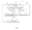
Toujours dans le cadre du contrôle de flux thermique sur un piston, et à titre d'exemple non exhaustif, on va maintenant décrire de façon détaxé les principales phases étapes de ce contrôle par référence au bloc diagramme 2 de la figure 4.Still in the context of the thermal flow control on a piston, and by way of non-exhaustive example, we will now describe zero-rated the main stages of this control by reference to block diagram 2 of Figure 4.
On se référera également à la configuration de moteur décrite sur la figure 2. En effet, pour fixer les idées, on suppose que le moteur 3 comprend quatre cylindres, 1a à 1d, et qu'il est équipé de quatre capteurs de pression cylindre 34, et d'un capteur 35 de température de la charge dans le répartiteur 31.Reference is also made to the engine configuration depicted in Figure 2. In order to fix ideas, it is assumed that the
Le flux thermique contrôlé est ici le flux thermique sur chaque piston (par exemple figure 1 : 12) et l'actionneur est, par exemple, la quantité de carburant, ci-après dénommée Qcarb.The controlled heat flow is here the heat flow on each piston (for example Figure 1: 12) and the actuator is, for example, the amount of fuel, hereinafter referred to as Qcarb .
Du fait de la nature de l'actionneur mis en oeuvre, comme il a été indiqué, le contrôle de flux thermique ne peut être réalisé ici que sur la pleine charge.Because of the nature of the actuator implemented, as has been indicated, the heat flow control can be achieved here only on the full load.
Le régulateur est un régulateur de type dit "PID" (pour action proportionnelle - intégrale - dérivée) classique utilisé de façon générique pour le contrôle des moteurs.The regulator is a regulator of type known as "PID" (for proportional action - integral - derivative) classic used generically for the control of the engines.
Les données d'entrées, stockés dans des moyens de mémoire associés au calculateur 32, sont les suivantes :
- cartographie d'un paramètre "régime/charge des flux thermiques" sur chaque piston ;
- paramètre "Offsets" de quantité de carburant ;
- cartographie des paramètres "quantités de carburant nominales (Qcarb)" ; et
- paramètre "tolérance maximale sur l'erreur de consigne de flux thermique", que l'on notera ε L .
- mapping of a parameter "speed / load of heat flows" on each piston;
- "Offsets" parameter of fuel quantity;
- mapping of nominal fuel quantity (Qcarb) parameters; and
- parameter "maximum tolerance on the thermal flow setpoint error", which will be noted ε L.
Le paramètre "régime/charge" dépend des points de fonctionnement du moteur 3. Chaque point de fonctionnement est notamment caractérisé par :
- le régime moteur en tr/mn; et
- la charge du moteur, c'est-à-dire le couple exprimé en Nm et la puissance en kW
- the engine speed in rpm; and
- the motor load, that is to say the torque expressed in Nm and the power in kW
Il est donc possible de construire une cartographie en deux dimensions des niveaux de flux thermiques pour chaque point de fonctionnement du moteur 3.It is therefore possible to construct a two-dimensional mapping of the heat flux levels for each operating point of the
Le paramètre appelé "Offset" correspond au pas de la variation de la quantité de carburant nécessaire pour modifier les flux thermiques. A titre d'exemple non limitatif, ce pas est typiquement de l'ordre 0,2 mg par coup. Cette quantité est déterminée lors d'une phase initiale de développement en fonction du moteur et des sensibilités des flux thermiques à ce paramètre.The parameter called "Offset" corresponds to the pitch of the variation of the quantity of fuel necessary to modify the thermal flows. As non-limiting example, this step is typically of the order 0.2 mg per shot. This quantity is determined during an initial phase of development depending on the engine and the sensitivities of the heat flows to this parameter.
Si on se réfère de nouveau au bloc diagramme 2 de la figure 4, le bloc 20 effectue le calcul du flux thermique au piston (par exemple figure 1 : 12). Il reçoit les résultats des calculs effectués par les blocs 26 et 27 décrits ci-après (liaisons 260 et 270).Referring again to block diagram 2 of FIG. 4, block 20 calculates heat flow to the piston (for example, FIG. 1: 12). It receives the results of the calculations made by the
Les résultats de ces calculs (liaison 200) sont transmis au bloc 21 qui effectue le calcul de l'erreur sur le flux thermique suivant: ![]()
![]()
Si ε > εL, le résultat est transmis au bloc 23 pour y être enregistré (liaison 210), dans le cas contraire, si ε < ε L , le résultat est transmis au bloc 24 pour y être enregistré (liaison 211).If ε> ε L , the result is transmitted to block 23 to be recorded (link 210), otherwise, if ε <ε L , the result is transmitted to block 24 to be recorded (link 211).
Dans le deuxième cas, puisque l'erreur calculée ε est inférieure à l'erreur de consigne ε L , le résultat est transmis au bloc 26 (liaison 240) pour application de la quantité nominale de carburant Qcarb. En effet, puisque l'actionneur de contrôle de flux thermique est ce paramètre, il n'y a pas lieu de le modifier. La sortie du bloc 26 est, comme précédemment indiqué rebouclée (liaison 260) sur le bloc 20 de calcul de flux thermique au piston.In the second case, since the calculated error ε is smaller than the set error ε L , the result is transmitted to block 26 (link 240) for applying the nominal quantity of fuel Qcarb. Indeed, since the heat flow control actuator is this parameter, there is no need to change it. The output of the
Lorsque l'erreur calculée ε est supérieure à l'erreur de consigne ε L , il y a lieu d'entreprendre une action corrective. La sortie du bloc 23 est transmise (liaison 230) au bloc de calcul 25. Celui-ci effectue un calcul de régulation consistant en la détermination de l'offset de Qcarb permettant de minimiser l'erreur ε. Le résultat est transmis (liaison 250) au bloc de calcul 27. Ce dernier détermine une nouvelle valeur de Qcarb satisfaisant la relation suivante : ![]()
![]()
La sortie du bloc 27 est rebouclée, comme il a été précédemment indiqué (liaison 270) sur le bloc 20 de calcul de flux thermique au piston.The output of the
Les calculs nécessaires et les stockages de données sont effectués de façon avantageuse en recourant à un calculateur numérique 32, du type à programme enregistré ou tout organe similaire. Comme il a été indiqué, de tels calculateurs sont couramment utilisés dans les moteurs de conception moderne. Il suffit donc d'adapter le programme enregistré pour implémenter les sous-programmes et/ou routines spécifiques au procédé de l'invention. Cette adaptation, en soi, est à la portée de l'homme de métier et n'implique ni accroissement de complexité, ni coût supplémentaire significatifs.The necessary calculations and data storage are advantageously carried out using a
Cependant, les calculs et les opérations associées ci-dessus pourraient tout aussi bien être réalisés par des circuits électroniques dédiés sans sortir du cadre de l'invention.However, the calculations and operations associated above could equally well be performed by dedicated electronic circuits without departing from the scope of the invention.
Sur cet exemple significatif, mais non exhaustif, on constate bien que l'invention atteint bien les buts qu'elle s'était fixée.In this significant but not exhaustive example, it is clear that the invention achieves the goals it has set for itself.
En effet, le procédé selon l'invention permet de contrôler directement, en boucle fermée et en temps réel, les niveaux de flux thermiques appliqués aux composants du moteur.Indeed, the method according to the invention makes it possible to directly control, in a closed loop and in real time, the heat flux levels applied to the components of the engine.
De façon plus générique, on peut résumer la phase de contrôle des flux thermiques sur des composants du moteur comme indiqué ci-après.More generically, it is possible to summarize the heat flow control phase on engine components as indicated below.
Cette phase comprend au moins les étapes suivantes :
- la détermination pendant la phase initiale d'une cartographie de valeurs de consigne de flux thermique pour chaque point de fonctionnement du moteur thermique;
- la détermination pendant la phase initiale d'un paramètre dit "tolérance maximale d'erreur de consigne de flux thermique" ;
- l'enregistrement de ces données dans des moyens de mémoire ;
- le choix d'un ou plusieurs paramètres caractéristique estimés comme actionneur pour agir sur le fonctionnement du moteur thermique et l'enregistrement d'une valeur de consigne de cet actionneur ;
- la détermination des valeurs du flux thermique instantané sur un ou plusieurs composants du moteur thermique ;
- le calcul d'une valeur d'erreur de flux thermique égale à la différence entre la valeur du flux thermique instantané et les valeurs de consigne de flux thermique pour chaque point de fonctionnement du moteur ; et
- la correction de la valeur de consigne de l'actionneur seulement et seulement si la valeur d'erreur est supérieure au paramètre "tolérance maximale d'erreur de consigne", de manière à minimiser la valeur d'erreur de flux thermique, l'enregistrement dans des moyens de mémoire de cette nouvelle valeur de consigne de l'actionneur et son application à des moyens de commande pour modifier le fonctionnement du moteur thermique.
- determining during the initial phase a mapping of heat flow setpoint values for each operating point of the heat engine;
- the determination during the initial phase of a parameter called "maximum tolerance of thermal flow setpoint error";
- recording of these data in memory means;
- the choice of one or more characteristic parameters estimated as an actuator for acting on the operation of the heat engine and the recording of a set value of this actuator;
- determining the values of the instantaneous heat flux on one or more components of the heat engine;
- calculating a thermal flux error value equal to the difference between the value of the instantaneous heat flux and the heat flow setpoint values for each operating point of the engine; and
- the correction of the actuator setpoint only and only if the error value is greater than the parameter "maximum error tolerance setpoint", so as to minimize the heat flow error value, the recording in memory means of this new setpoint value of the actuator and its application to control means for modifying the operation of the heat engine.
Il doit être clair cependant que l'invention n'est pas limitée aux seuls exemples de réalisations explicitement décrits, notamment en relation avec les figures 1 à 4.It should be clear, however, that the invention is not limited to the only examples of embodiments explicitly described, particularly in relation to FIGS. 1 to 4.
Comme il a été notamment précisé, l'invention s'applique indifféremment à un moteur diesel ou à un moteur à essence.As has been specified in particular, the invention applies equally to a diesel engine or a gasoline engine.
Enfin, les exemples numériques n'ont été fournis que pour mieux fixer les idées et ne sauraient constituer une quelconque limitation de la portée de l'invention. Ils procèdent d'un choix technologique à la portée de l'Homme de Métier.Finally, the numerical examples have been provided only to better fix the ideas and can not constitute any limitation of the scope of the invention. They proceed from a technological choice within the reach of the Man of Profession.
Claims (20)


Applications Claiming Priority (1)
| Application Number | Priority Date | Filing Date | Title |
|---|---|---|---|
| FR0654387A FR2907509A1 (en) | 2006-10-19 | 2006-10-19 | Characteristic parameter e.g. mass of air, estimating method for e.g. diesel engine, involves controlling thermal flux applied to component e.g. piston, of engine in closed loop, from derived magnitude of estimated characteristic parameters |
Publications (1)
| Publication Number | Publication Date |
|---|---|
| EP1916404A1 true EP1916404A1 (en) | 2008-04-30 |
Family
ID=38055211
Family Applications (1)
| Application Number | Title | Priority Date | Filing Date |
|---|---|---|---|
| EP07301462A Withdrawn EP1916404A1 (en) | 2006-10-19 | 2007-10-12 | Method of estimating characteristic parameters of a heat engine and of controlling thermal flux applied to components of this engine |
Country Status (2)
| Country | Link |
|---|---|
| EP (1) | EP1916404A1 (en) |
| FR (1) | FR2907509A1 (en) |
Cited By (2)
| Publication number | Priority date | Publication date | Assignee | Title |
|---|---|---|---|---|
| FR3102515A1 (en) | 2019-10-29 | 2021-04-30 | Psa Automobiles Sa | Method for estimating the thermal state of an engine component and method for controlling GMP controls |
| WO2023117060A1 (en) * | 2021-12-21 | 2023-06-29 | Wärtsilä Finland Oy | Method of and apparatus for controlling phasing of combustion of fuel in a multi-cylinder internal combustion engine |
Citations (5)
| Publication number | Priority date | Publication date | Assignee | Title |
|---|---|---|---|---|
| US5974792A (en) | 1995-09-18 | 1999-11-02 | Nippondenso Co., Ltd. | Internal combustion engine control with fast exhaust catalyst warm-up |
| EP1072766A1 (en) * | 1999-07-30 | 2001-01-31 | Valeo Thermique Moteur | Cooling controlling device of an internal combustion engine of a motor vehicle |
| EP1291514A2 (en) * | 2001-09-07 | 2003-03-12 | Mitsubishi Jidosha Kogyo Kabushiki Kaisha | Exhaust emission control device of engine |
| WO2003048550A1 (en) * | 2001-12-04 | 2003-06-12 | Robert Bosch Gmbh | Method, computer program and control and/or regulating device for operating an internal combustion engine |
| FR2854202A1 (en) * | 2003-04-23 | 2004-10-29 | Bosch Gmbh Robert | Vehicle internal combustion engine control method, involves modeling engine temperature of internal combustion engine and integrating difference between thermal flow entering and leaving engine based on engine ignition temperature |
-
2006
- 2006-10-19 FR FR0654387A patent/FR2907509A1/en not_active Withdrawn
-
2007
- 2007-10-12 EP EP07301462A patent/EP1916404A1/en not_active Withdrawn
Patent Citations (5)
| Publication number | Priority date | Publication date | Assignee | Title |
|---|---|---|---|---|
| US5974792A (en) | 1995-09-18 | 1999-11-02 | Nippondenso Co., Ltd. | Internal combustion engine control with fast exhaust catalyst warm-up |
| EP1072766A1 (en) * | 1999-07-30 | 2001-01-31 | Valeo Thermique Moteur | Cooling controlling device of an internal combustion engine of a motor vehicle |
| EP1291514A2 (en) * | 2001-09-07 | 2003-03-12 | Mitsubishi Jidosha Kogyo Kabushiki Kaisha | Exhaust emission control device of engine |
| WO2003048550A1 (en) * | 2001-12-04 | 2003-06-12 | Robert Bosch Gmbh | Method, computer program and control and/or regulating device for operating an internal combustion engine |
| FR2854202A1 (en) * | 2003-04-23 | 2004-10-29 | Bosch Gmbh Robert | Vehicle internal combustion engine control method, involves modeling engine temperature of internal combustion engine and integrating difference between thermal flow entering and leaving engine based on engine ignition temperature |
Cited By (3)
| Publication number | Priority date | Publication date | Assignee | Title |
|---|---|---|---|---|
| FR3102515A1 (en) | 2019-10-29 | 2021-04-30 | Psa Automobiles Sa | Method for estimating the thermal state of an engine component and method for controlling GMP controls |
| WO2021084173A1 (en) | 2019-10-29 | 2021-05-06 | Psa Automobiles Sa | Method for estimating the thermal state of an engine component and method for controlling powertrain commands |
| WO2023117060A1 (en) * | 2021-12-21 | 2023-06-29 | Wärtsilä Finland Oy | Method of and apparatus for controlling phasing of combustion of fuel in a multi-cylinder internal combustion engine |
Also Published As
| Publication number | Publication date |
|---|---|
| FR2907509A1 (en) | 2008-04-25 |
Similar Documents
| Publication | Publication Date | Title |
|---|---|---|
| EP1815118B1 (en) | Device and method for determination of the quantity of nox emitted by a diesel engine in a motor vehicle and diagnostic and engine management system comprising such a device | |
| WO2019110882A1 (en) | System and method for controlling an internal combustion engine provided with an exhaust gas post-treatment system of the selective catalysis type | |
| EP1936156B1 (en) | Method of controlling an internal combustion engine | |
| WO1998031927A1 (en) | Device for controlling an internal combustion engine with controlled ignition and direct injection | |
| EP1916404A1 (en) | Method of estimating characteristic parameters of a heat engine and of controlling thermal flux applied to components of this engine | |
| EP2430298B1 (en) | Estimation of the nitrogen oxide (nox) concentration in an internal combustion engine | |
| FR2847944A1 (en) | I.c. engine fuel/air mixture regulating procedure with multiple injection consists of adjusting fuel mass on each injection operation | |
| WO2016012095A1 (en) | Method for determining the total pressure in the cylinder of an engine | |
| FR2835281A1 (en) | Method for estimating mass of air admitted into engine combustion chamber consists of modeling air mass as function of pressure variation in combustion chamber from polytropic gas compression law | |
| FR2819017A1 (en) | System for controlling a turbo-charged motor vehicle IC engine, uses sensors and an ECU to determine guide values of torque loads and regulates the engine parameters accordingly | |
| FR2894626A1 (en) | METHOD FOR MANAGING AN INTERNAL COMBUSTION ENGINE | |
| EP2256322B1 (en) | Effect of the nox control on the combustion noise control in an internal combustion engine | |
| EP1671023A1 (en) | Engine air supply control method which is intended, for example, for the control of a turbocharged engine | |
| EP1606501A1 (en) | Method of measuring ambient pressure in a turbocharged engine | |
| FR2870887A1 (en) | Internal combustion engine e.g. gasoline engine, controlling method for motor vehicle, involves controlling overlapping of valve strokes so that inlet and exhaust valves are open and fuel arrives in exhaust gas pipe for being burnt with air | |
| FR2871195A1 (en) | Internal combustion engine monitoring process for motor vehicle, involves adjusting controlled variable on value from requests on engine`s output variable if request different from pedal actuation request exists, or on actuation based value | |
| FR2903148A1 (en) | METHOD AND INSTALLATION FOR MANAGING AN INTERNAL COMBUSTION ENGINE. | |
| EP1647692A1 (en) | Air inlet control method for an internal combustion engine and automotive vehicle for applying this method | |
| FR3084114A1 (en) | METHOD FOR CONTROLLING COMBUSTION IN AN ENGINE | |
| EP3004608B1 (en) | Method for estimating the pollutant emissions of an internal combustion engine and related method for controlling the engine | |
| WO2002040840A1 (en) | Method and device for controlling the operation of a self-ignition internal combustion engine | |
| EP3475556B1 (en) | Method for determining the advance of ignition of an internal combustion engine and method for controlling an engine using such a method | |
| EP4234909A1 (en) | Method for controlling richness in a carburized mixture of an internal combustion engine of a motor vehicle | |
| FR2793524A1 (en) | METHOD FOR IMPLEMENTING A FUEL SUPPLY SYSTEM OF AN INTERNAL COMBUSTION ENGINE | |
| FR2871521A1 (en) | Average and maximum gas pressure estimating system for diesel engine, has estimation unit for estimating average and maximum gas pressure in exhaust manifold according to pressure in cylinder of engine |
Legal Events
| Date | Code | Title | Description |
|---|---|---|---|
| PUAI | Public reference made under article 153(3) epc to a published international application that has entered the european phase |
Free format text: ORIGINAL CODE: 0009012 |
|
| AK | Designated contracting states |
Kind code of ref document: A1 Designated state(s): AT BE BG CH CY CZ DE DK EE ES FI FR GB GR HU IE IS IT LI LT LU LV MC MT NL PL PT RO SE SI SK TR |
|
| AX | Request for extension of the european patent |
Extension state: AL BA HR MK RS |
|
| 17P | Request for examination filed |
Effective date: 20081002 |
|
| AKX | Designation fees paid |
Designated state(s): AT BE BG CH CY CZ DE DK EE ES FI FR GB GR HU IE IS IT LI LT LU LV MC MT NL PL PT RO SE SI SK TR |
|
| GRAP | Despatch of communication of intention to grant a patent |
Free format text: ORIGINAL CODE: EPIDOSNIGR1 |
|
| STAA | Information on the status of an ep patent application or granted ep patent |
Free format text: STATUS: THE APPLICATION IS DEEMED TO BE WITHDRAWN |
|
| 18D | Application deemed to be withdrawn |
Effective date: 20100529 |