EP1428992A1 - Breather device of engine - Google Patents
Breather device of engine Download PDFInfo
- Publication number
- EP1428992A1 EP1428992A1 EP02746069A EP02746069A EP1428992A1 EP 1428992 A1 EP1428992 A1 EP 1428992A1 EP 02746069 A EP02746069 A EP 02746069A EP 02746069 A EP02746069 A EP 02746069A EP 1428992 A1 EP1428992 A1 EP 1428992A1
- Authority
- EP
- European Patent Office
- Prior art keywords
- breather chamber
- breather
- blow
- gas
- chamber
- Prior art date
- Legal status (The legal status is an assumption and is not a legal conclusion. Google has not performed a legal analysis and makes no representation as to the accuracy of the status listed.)
- Granted
Links
Images






Classifications
-
- F—MECHANICAL ENGINEERING; LIGHTING; HEATING; WEAPONS; BLASTING
- F01—MACHINES OR ENGINES IN GENERAL; ENGINE PLANTS IN GENERAL; STEAM ENGINES
- F01M—LUBRICATING OF MACHINES OR ENGINES IN GENERAL; LUBRICATING INTERNAL COMBUSTION ENGINES; CRANKCASE VENTILATING
- F01M13/00—Crankcase ventilating or breathing
- F01M13/04—Crankcase ventilating or breathing having means for purifying air before leaving crankcase, e.g. removing oil
- F01M13/0416—Crankcase ventilating or breathing having means for purifying air before leaving crankcase, e.g. removing oil arranged in valve-covers
-
- F—MECHANICAL ENGINEERING; LIGHTING; HEATING; WEAPONS; BLASTING
- F01—MACHINES OR ENGINES IN GENERAL; ENGINE PLANTS IN GENERAL; STEAM ENGINES
- F01M—LUBRICATING OF MACHINES OR ENGINES IN GENERAL; LUBRICATING INTERNAL COMBUSTION ENGINES; CRANKCASE VENTILATING
- F01M13/00—Crankcase ventilating or breathing
- F01M13/04—Crankcase ventilating or breathing having means for purifying air before leaving crankcase, e.g. removing oil
-
- F—MECHANICAL ENGINEERING; LIGHTING; HEATING; WEAPONS; BLASTING
- F01—MACHINES OR ENGINES IN GENERAL; ENGINE PLANTS IN GENERAL; STEAM ENGINES
- F01M—LUBRICATING OF MACHINES OR ENGINES IN GENERAL; LUBRICATING INTERNAL COMBUSTION ENGINES; CRANKCASE VENTILATING
- F01M13/00—Crankcase ventilating or breathing
-
- F—MECHANICAL ENGINEERING; LIGHTING; HEATING; WEAPONS; BLASTING
- F01—MACHINES OR ENGINES IN GENERAL; ENGINE PLANTS IN GENERAL; STEAM ENGINES
- F01M—LUBRICATING OF MACHINES OR ENGINES IN GENERAL; LUBRICATING INTERNAL COMBUSTION ENGINES; CRANKCASE VENTILATING
- F01M13/00—Crankcase ventilating or breathing
- F01M2013/0038—Layout of crankcase breathing systems
- F01M2013/0044—Layout of crankcase breathing systems with one or more valves
-
- F—MECHANICAL ENGINEERING; LIGHTING; HEATING; WEAPONS; BLASTING
- F01—MACHINES OR ENGINES IN GENERAL; ENGINE PLANTS IN GENERAL; STEAM ENGINES
- F01M—LUBRICATING OF MACHINES OR ENGINES IN GENERAL; LUBRICATING INTERNAL COMBUSTION ENGINES; CRANKCASE VENTILATING
- F01M13/00—Crankcase ventilating or breathing
- F01M13/04—Crankcase ventilating or breathing having means for purifying air before leaving crankcase, e.g. removing oil
- F01M2013/0438—Crankcase ventilating or breathing having means for purifying air before leaving crankcase, e.g. removing oil with a filter
-
- F—MECHANICAL ENGINEERING; LIGHTING; HEATING; WEAPONS; BLASTING
- F01—MACHINES OR ENGINES IN GENERAL; ENGINE PLANTS IN GENERAL; STEAM ENGINES
- F01M—LUBRICATING OF MACHINES OR ENGINES IN GENERAL; LUBRICATING INTERNAL COMBUSTION ENGINES; CRANKCASE VENTILATING
- F01M13/00—Crankcase ventilating or breathing
- F01M13/04—Crankcase ventilating or breathing having means for purifying air before leaving crankcase, e.g. removing oil
- F01M2013/0461—Crankcase ventilating or breathing having means for purifying air before leaving crankcase, e.g. removing oil with a labyrinth
Definitions
- the present invention relates to a structure of a breather device for an engine, made in a valve arm chamber that covers an upper side of a cylinder head.
- an engine has a breather chamber in a valve arm casing that covers an upper side of a cylinder head of an engine is formed a breather chamber, in which blow-by gas including oil mist is separated into oil component and gas component.
- This breather chamber is made as a space surrounded by side walls of the valve arm casing, ribs jutting from inside surfaces of the valve arm casing, and a base plate installed at regular intervals from the inside surfaces of the valve arm casing.
- a filter gauze arranged in the breather chamber traps oil mist (oil component) in blow-by gas, and removes it from the gas.
- the conventional breather device merely comprising the filter gauze at an inlet portion of the breather chamber has insufficient ability for removing oil component.
- the intake gas is mixed with oil, thereby increasing emission in exhaust gas far from decreasing it.
- a pressure-regulating valve is arranged at an outlet portion of the breather chamber for blow-by gas so as to regulate pressure in the breather chamber.
- a conventional pressure-regulating valve 40 comprises a diaphragm 41, a spring 42, and a center plate 43, so that the spring 42 energizes the diaphragm 41 downward, with the center plate 43 put between the spring 42 and the diaphragm 41.
- the diaphragm 41 cuts off communication between a gas passage 44 to the intake side and a breather chamber 45.
- the pressure in the breather chamber 45 arises above a predetermined pressure, the diaphragm 41 is pressed and moved upward, so that the pressure-regulating valve 40 opens to bring the breather chamber 45 into communication with the gas passage 44.
- This conventional pressure-regulating valve requires such many parts of the spring 42 and the center plate 43, thereby being expensive and complicated.
- a conventional breather chamber is connected to an intake manifold through a breather pipe for recirculating blow-by gas through the breather chamber into intake gas.
- a conventional breather chamber is connected to an intake manifold through a breather pipe for recirculating blow-by gas through the breather chamber into intake gas.
- An object of the present invention is to provide a breather chamber formed in a valve arm chamber of an engine, enhancing the effect of removing oil mist from blow-by gas.
- plural rooms are formed in the breather chamber so as to ensure a long passage of blow-by gas in the breather chamber, thereby enhancing the effect of removing oil mist, and lowering the increase of emission in exhaust gas caused by recirculating the blow-by gas into intake gas.
- plural oil trap members for trapping oil mist in the blow-by gas are arranged in the breather chamber so as to remove oil mist from the blow-by gas by steps, thereby enhancing the effect of removing oil mist.
- a holder for holding the oil trap member which traps oil mist in the blow-by gas is arranged in the breather chamber, wherein the holder is separated from a member forming the valve arm chamber, thereby facilitating exchange of the oil trap member and maintenance of the valve arm chamber.
- partitions alternately extended from bottom and ceiling surfaces of the breather chamber divide the interior of the breather chamber into horizontally juxtaposed plural rooms.
- the plural rooms can be simply formed so as to ensure the sufficiently long passage of blow-by gas without changing the height of the engine.
- an oil trap member for trapping oil mist in the blow-by gas is arranged at a blow-by gas inlet of the breather chamber, and a discharge vent is formed near the oil trap member so as to naturally discharge oil collected on the bottom in the breather chamber. Blow-by gas is let into the breather chamber through this oil trap member so as to surely remove oil mist, thereby lowering the consumption of oil.
- the blow-by gas inlet is formed in the holder, and a guide portion extended outward from the breather chamber is provided to the inlet so as to get the oil mist adhering thereto before the blow-by gas is let into the breather chamber, thereby removing the oil mist.
- a pressure-regulating valve for regulating pressure is arranged in the room nearest an outlet of the breather chamber among the plural rooms formed in the breather chamber. Accordingly, while the sufficiently long passage of the blow-by gas is ensured in the breather chamber and the enhanced effect of removing oil mist is ensured, the pressure in the valve arm chamber is keep constant, thereby preventing an oil seal from deflecting and deteriorating.
- a second object of the present invention is to provide a pressure-regulating valve for regulating pressure in the breather chamber which is arranged at a blow-by gas outlet portion of the breather chamber, wherein the pressure-regulating valve is simple and economic with reduction of required parts.
- a pressure-regulating valve is opened and closed by sliding movement of a ball-like member, wherein the ball-like member slides basing on the blow-by gas pressure in the breather chamber.
- the present valve assembly can be inexpensive and simple because it doest not require members such as a spring and a center frame used by the conventional pressure-regulating valve.
- a pressure-regulating valve may comprise a diaphragm arranged above an outlet of the breather chamber, and a weight member downwardly energizing a valve surface of the diaphragm, wherein the outlet of the breather chamber essentially closed by the valve surface of the diaphragm is opened against the energizing force of the weight member by increasing the blow-by gas pressure in the breather chamber.
- the present valve assembly can be inexpensive and simple because it doest not require members such as a spring and a center frame used by the conventional pressure-regulating valve.
- the pressure-regulating valve may comprise a diaphragm arranged above an outlet of the breather chamber, wherein the surface of the valve of the diaphragm is energized downward by its own elasticity, and the outlet of the breather chamber essentially closed by the valve surface of the diaphragm is opened against the elastic force of the diaphragm by increasing the blow-by gas pressure in the breather chamber.
- the present valve assembly can be inexpensive and simple because it doest not require members such as a spring and a center frame used by the conventional pressure-regulating valve.
- the diaphragm having the center frame is not subjected to pressure caused by the center frame, thereby being improved in durability.
- a third object of the present invention is to provide an arrangement of recirculating blow-by gas through a breather chamber into intake gas, wherein oil component moved to intake side causing declination of engine performance is reduced.
- an orifice is formed at a blow-by gas inlet of an intake manifold for introducing blow-by gas passing through the breather chamber so that pressure in the valve arm chamber including the breather chamber is stabilized without microseisms, thereby keeping a seal member from deteriorating.
- the orifice prevents rapid entrance of blow-by gas into the intake manifold so as to reduce oil component moved to the intake side.
- a pressure-regulating valve for regulating pressure in the breather chamber is additionally arranged at the blow-by gas outlet of the breather chamber, the pressure in the valve arm chamber is kept constant, thereby enhancing the effect of preventing an oil seal from deflecting and deteriorating, and the effect of reducing oil component moved to the intake side with prevention of rapid entrance of blow-by gas into the intake manifold.
- a device for preventing oil hummer is interposed between the breather chamber and the intake manifold so as to prevent sudden entrance of much oil into the intake side, thereby keeping engine performance from falling.
- the device for preventing oil hummer may be combined with the orifice at the blow-by gas inlet portion of the intake manifold, or with the pressure-regulating valve at the blow-by gas outlet of the breather chamber, or with both of them, so as to ensure synergy of the above-mentioned effects.
- a valve arm casing 2 is arranged above a cylinder head 1 of an engine so as to constitute a valve arm chamber 5 in which an upper part of an inlet valve, an upper part of an exhaust valve, an upper part of a push rod 14, a valve arm 15, a fuel injection valve, and the like are installed.
- a pressure control chamber 3 is attached to the top surface of the valve arm casing 2, and a breather chamber 22 is formed at the lower part of the pressure control chamber 3.
- the breather chamber 22 is surrounded by inner surfaces of the valve arm casing 2 and a shielding board 7 arranged in the valve arm casing 2.
- the breather chamber 22 is provided therein with a partition 23 extended from the bottom surface thereof and a partition 2a extended from the ceiling surface thereof, which are alternately arranged to divide the inner space of the breather chamber 22 into horizontally juxtaposed rooms, i.e., a first room 22a, a second room 22b and a third room 23c.
- a holder 11 is arranged in a lower part of the first room 22a of the breather chamber 22 so as to hold an oil trap 10 for trapping oil mist in the blow-by gas, and a blow-by gas inlet is formed in the holder 11.
- the holder 11 has a guide portion 11a extended outward (downward in Fig.2) from the breather chamber 22 so that oil mist in the blow-by gas may adhere to the guide portion 11a before the blow-by gas is let into the breather chamber 22, thereby removing the oil mist.
- the oil trap 10 is a netlike member made of steel wool or the like.
- the oil trap 10 is held in the space surrounded by the holder 11 and sidewalls of the valve arm casing 2. As shown in Fig.4, the holder 11 is formed separately from the valve arm chamber 5, thereby facilitating exchange of the oil trap 10 and maintenance of the valve arm chamber 5.
- Another oil trap 10 is also arranged in the second room 22b of the breather chamber 22.
- a blow-by gas outlet formed in the third room 22c is connected to the pressure control chamber 3.
- the number of rooms formed in the breather chamber 22 and the number of oil traps arranged in the breather chamber 22 are not limited.
- the blow-by gas enters the inlet of the breather chamber 22 along the guide portion 11a of the holder 11, passes the oil trap 10 held by the holder 11, and enters the first room 22a of the breather chamber 22.
- the blow-by gas let into the breather chamber 22 passes through the first room 22a, the second room 22b, and the third room 22c in turn, and it is guided from the outlet of the third room 22c to the intake side of the engine through the pressure control chamber 3.
- the blow-by gas passes the oil trap 10
- the oil trap 10 traps oil mist so as to clear the blow-by gas of oil component.
- the oil trap 10 arranged in the second room 22b, while the blow-by gas passing therethrough traps oil mist so as to clear the blow-by gas of oil component.
- blow-by gas passes through the first room 22a, the second room 22b, and the third room 22c, oil mist in the blow-by gas adheres to wall surfaces of the breather chamber 22, thereby being removed from the blow-by gas.
- the oil traps 10 remove oil mist from the blow-by gas by steps.
- the plural partitions can easily form the horizontally juxtaposed plural rooms in the breather chamber 22 so that such a significantly long passage of blow-by gas as to enhance the effect of removing oil mist can be ensured in the breather chamber 22 without changing the height of the engine. Therefore, emission in exhaust gas and consumption of oil, which tend to be increased by recirculating blow-by gas into intake gas, are restricted.
- a discharge vent 11b is formed in a lower portion of the holder 11 near the oil trap 10 arranged over the blow-by gas inlet of the breather chamber 22, and a discharge vent 23a is formed in a lower portion of the partition extended from the bottom face side, i.e., the partition 23 arranged between the first room 22a and the second room 22b in this embodiment.
- the oil trap 10 held above the discharge vent 11b formed in the holder 11 is surely prevented from being immersed in the oil discharged from the breather chamber 22 through the discharge vent 11b, whereby the capacity of filtering blow-by gas by the oil trap 10 can be preserved.
- the breather chamber 22 is provided with the blow-by gas outlet at the third room 22c in connection with the pressure control chamber 3.
- a gas passage 3a connected to the breather chamber 22 is formed from the pressure control chamber 3, and a pressure-regulating valve 18 for regulating pressure in the breather chamber 22 is interposed between the gas passage 3a and the breather chamber 22.
- the pressure-regulating valve 18 is opened and closed according to sliding movement of a ball-like member 19, so that the blow-by gas pressure is regulated depending on the weight of the ball-like member 19.
- the pressure-regulating valve 18 essentially separates the breather chamber 22 and the gas passage 3a from each other.
- the ball-like member 19 slides upward against its gravity and opens the outlet of the breather chamber 22 having been closed by the ball-like member 19, thereby bringing the breather chamber 22 into communication with the gas passage 3a, so that the blow-by gas from which oil component is removed passes through the gas passage 3a.
- the pressure in the valve arm chamber 5 is kept constant, thereby preventing an oil seal from deflecting and deteriorating.
- the present valve which does not require a spring and a center plate is inexpensive and simple.
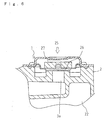
- a pressure-regulating valve 25 comprises a diaphragm 26 arranged above the outlet of the breather chamber 22, and a weight member 27 put on the diaphragm 26.
- the weight member 27 energizes a valve surface of the diaphragm 26 downward.
- the diaphragm 26 is pushed up and moves upward against the energizing force of the weight member 27, whereby the outlet of the breather chamber 22 having been closed by the valve surface of the diaphragm 26 is opened, and the breather chamber 22 comes to communicate with the gas passage 3a.
- valve of this embodiment does not have a spring and a center plate, thereby being inexpensive and simple.
- a pressure-regulating valve may be made as follows.
- a pressure-regulating valve 28 comprises an elastic member serving as a diaphragm 29 arranged above the outlet of the breather chamber 22, wherein a valve surface of the diaphragm 29 is energized downward by its own elasticity.
- the diaphragm 29 assembled in the pressure-regulating valve 28 has the valve surface 29b for opening and closing the gas passage 3a, wherein the valve surface 29b is energized downward by an elastic edge 29b formed along its periphery.
- the present valve Compared with a conventional pressure-regulating valve having a diaphragm energized by a spring, the present valve has neither a spring nor a center plate, thereby being inexpensive and facilitating for easy assembly.
- the diaphragm is improved in durability because it has no center plate pressed thereon.
- the blow-by gas from which oil component is removed in the breather chamber, opens the pressure-regulating valve, and passes through the gas passage 3a, and then goes into an intake manifold 16.
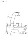
- a breather pipe 21 connects the breather chamber 22 to the intake manifold 16, and an orifice 16 is formed at a blow-by gas inlet of the intake manifold 16.
- the orifice 16a prevents the pressure in the valve arm chamber 5 including the breather chamber 22 from microseisms and stabilizes it, thereby keeping a seal member from deteriorating.
- the orifice 16a also prevents blow-by gas from being rapidly let into the intake manifold 16, thereby reducing oil component moved to the intake side.
- an oil hummer inhibiter 30 for preventing much oil from being admitted into the intake manifold 16 may be interposed at an intermediate portion of the breather pipe 24.
- the oil hummer inhibiter 30 has a main body 31 provided therein with a ball-like member 32.
- the main body 31 is formed in its topside with a gas passage 31a connected to the intake manifold 16 through a breather pipe 24a.
- the main body 31 is also formed in its lateral side with a gas passage 31b connected to the breather chamber 22 through a breather pipe 24b.
- the main body 31 is further formed in its bottom side with a gas passage 31c for letting oil collected in the main body 31 to the intake manifold 16 through a pipe 33.
- the ball-like member 32 essentially stays in the lower portion of the main body 31.
- the blow-by gas introduced into the main body 31 from the gas passage 31a connected to the breather pipe 24a is passed through the topside of the main body 31 and let into the intake manifold 16 through the gas passage 31b connected to the breather pipe 24b.
- the spouted oil flows into the main body 31 and the ball-like member 32 floating on the oil in the main body 31 moves upward and closes the upper gas passage 31b, thereby preventing sudden movement of oil to the intake side.
- the pressure-regulating valve 18 for regulating pressure in the breather chamber 22 is arranged at the blow-by gas outlet of the breather chamber 22, and the chock 16a is formed at the inlet of the intake manifold 16, into which the blow-by gas passing through the breather chamber 22 is let. Accordingly, the pressure in the valve arm chamber 5 including the breather chamber 22 is stabilized without microseisms causing deterioration and deflection of a seal member. Oil component moved to the intake side is reduced by the orifice 16a preventing sudden flow of blow-by gas into the intake manifold 16.
- oil hummer inhibiter 30 is interposed at the intermediate portion of the breather pipe 24 connecting the breather chamber 22 to the intake manifold 16, sudden flow of much oil into the intake side is prevented, thereby keeping engine performance from falling.
- the breather device of engine according to the present invention is useful because of its sufficient capacity of removing oil component, i.e., oil mist from blow-by gas.
Landscapes
- Engineering & Computer Science (AREA)
- Mechanical Engineering (AREA)
- General Engineering & Computer Science (AREA)
- Lubrication Details And Ventilation Of Internal Combustion Engines (AREA)
- Self-Closing Valves And Venting Or Aerating Valves (AREA)
- Devices For Conveying Motion By Means Of Endless Flexible Members (AREA)
Abstract
Description
Claims (16)
- A breather device of an engine comprising:characterized by a plurality of rooms (22a, 22b, 22c) formed in the breather chamber.a valve arm chamber (5); anda breather chamber (22) provided in the valve arm chamber so as to remove oil mist from blow-by gas,
- The breather device of an engine as set forth in claim 1, further comprising:a plurality of oil trap members (10) provided in the breather chamber so as to trap oil mist in blow-by gas.
- The breather device of an engine as set forth in claim 1, further comprising:a member (2, 7) forming the valve arm chamber;an oil trap member (10) provided in the breather chamber so as to trap oil mist in blow-by gas; anda holder (11) for holding the oil trap member, the holder being separate from the member forming the valve arm chamber.
- The breather device of an engine as set forth in claim 3, further comprising:a blow-by gas inlet formed in the holder; anda guide portion (11a) to the blow-by gas inlet being extended outward from the breather chamber.
- The breather device of an engine as set forth in claim 1, further comprising:wherein the partitions (23, 2a) are alternately arranged to divide the inside of the breather chamber into the plurality of the rooms, which are juxtaposed horizontally.a partition (23) extended from a bottom surface in the breather chamber; anda partition (2a) extended from a ceiling surface in the breather chamber,
- The breather device of an engine as set forth in claim 1, further comprising:an oil trap member (10) provided at a blow-by gas inlet of the breathe chamber so as to trap oil mist in blow-by gas; anda vent (11b, 23a) arranged near the oil trap member so as to discharge oil collected on the bottom in the breather chamber.
- The breather device of an engine as set forth in claim 1, further comprising:a pressure-regulating valve (18, 25, 28) for regulating pressure in the breather chamber, the pressure-regulating valve being disposed at the nearest room (22c) of the plurality of rooms formed in the breather chamber to an outlet of the breather chamber.
- A breather device of an engine comprising:characterized in that the pressure-regulating valve includes a ball-like member (19) which slides according to pressure in the breather chamber,a breather chamber (22); anda pressure-regulating valve (18) arranged at a blow-by gas outlet of the breather chamber so as to regulate pressure in the breather chamber,
wherein the pressure-regulating valve is opened and closed according to the sliding movement of the ball-like member. - A breather device of an engine comprising:characterized in that the pressure-regulating valve includes a diaphragm (26) disposed above the outlet of the breather chamber, the diaphragm having a valve surface for closing the outlet, and a weight member (27) downwardly energizing the valve surface of the diaphragm,a breather chamber (22); anda pressure-regulating valve (25) arranged at a blow-by gas outlet of the breather chamber so as to regulate pressure in the breather chamber,
wherein the outlet of the breather chamber essentially closed by the valve surface of the diaphragm is opened against the energizing force of the weight member by increasing blow-by gas pressure in the breather chamber. - A breather device for an engine comprising:characterized in that the pressure-regulating valve includes a diaphragm (29) disposed above the outlet of the breather chamber, the diaphragm having a valve surface (29b) for closing the outlet,a breather chamber (22); anda pressure-regulating valve (28) arranged at a blow-by gas outlet of the breather chamber so as to regulate pressure in the breather chamber,
wherein the valve surface of the diaphragm is energized downward by its elasticity, and
wherein the outlet of the breather chamber essentially closed by the valve surface of the diaphragm is opened against the energizing force of the diaphragm by increasing blow-by gas pressure in the breather chamber. - A breather device of an engine comprising:characterized by an orifice (16a) provided to the inlet of the intake manifold.a breather chamber (22), through which blow-by gas is passed to be recircluated into intake gas; andan intake manifold (16) having an inlet for introducing blow-by gas therein from the breather chamber,
- The breather device of an engine as set forth in claim 11, further comprising:a pressure-regulating valve (18, 25, 28) for regulating pressure in the breather chamber, the pressure-regulating valve being disposed at a blow-by gas outlet of the breather chamber.
- The breather device of an engine as set forth in claim 11, further comprising:an oil hummer inhibiting device (30) interposed between the breather chamber and the intake manifold.
- The breather device for an engine as set forth in claim 13, further comprising:a pressure-regulating valve (18, 25, 28) disposed at a blow-by gas outlet of the breather chamber.
- A breather device of an engine comprising:characterized in that an oil hummer inhibiting device (30) for preventing much oil from being admitted into the intake manifold is interposed between the breather chamber and the intake manifold.a breather chamber (22), through which blow-by gas is passed to be recircluated into intake gas; andan intake manifold (16) having an inlet for introducing blow-by gas therein from the breather chamber,
- A breather device of an engine as set forth in claim 15, further comprising:a pressure-regulating valve (18, 25, 28) disposed at a blow-by gas outlet of the breather chamber.
Applications Claiming Priority (7)
| Application Number | Priority Date | Filing Date | Title |
|---|---|---|---|
| JP2001283704A JP4521140B2 (en) | 2001-09-18 | 2001-09-18 | Engine breather equipment |
| JP2001283704 | 2001-09-18 | ||
| JP2001283705 | 2001-09-18 | ||
| JP2001283706 | 2001-09-18 | ||
| JP2001283706A JP2003090207A (en) | 2001-09-18 | 2001-09-18 | Breather device for engine |
| JP2001283705A JP2003090206A (en) | 2001-09-18 | 2001-09-18 | Breather device for engine |
| PCT/JP2002/007185 WO2003025354A1 (en) | 2001-09-18 | 2002-07-15 | Breather device of engine |
Publications (3)
| Publication Number | Publication Date |
|---|---|
| EP1428992A1 true EP1428992A1 (en) | 2004-06-16 |
| EP1428992A4 EP1428992A4 (en) | 2009-12-30 |
| EP1428992B1 EP1428992B1 (en) | 2011-05-04 |
Family
ID=27347527
Family Applications (1)
| Application Number | Title | Priority Date | Filing Date |
|---|---|---|---|
| EP02746069A Expired - Lifetime EP1428992B1 (en) | 2001-09-18 | 2002-07-15 | Breather device of engine |
Country Status (7)
| Country | Link |
|---|---|
| US (1) | US7243642B2 (en) |
| EP (1) | EP1428992B1 (en) |
| KR (1) | KR100874537B1 (en) |
| CN (1) | CN1272527C (en) |
| AT (1) | ATE508260T1 (en) |
| DE (1) | DE60239944D1 (en) |
| WO (1) | WO2003025354A1 (en) |
Cited By (5)
| Publication number | Priority date | Publication date | Assignee | Title |
|---|---|---|---|---|
| EP2087212A4 (en) * | 2006-12-01 | 2009-11-11 | Toyota Eng & Mfg North America | Engine head cover assembly having an integrated oil separator |
| US7942122B2 (en) | 2006-12-01 | 2011-05-17 | Toyota Motor Engineering & Manufacturing North America, Inc. | Engine head cover assembly having an integrated oil separator and a removable cover |
| WO2014046999A1 (en) * | 2012-09-19 | 2014-03-27 | Siemens Industry, Inc. | Drain hose connector with breather valve |
| EP3336325A1 (en) * | 2016-12-16 | 2018-06-20 | Kubota Corporation | Engine head cover |
| EP1961928B1 (en) * | 2007-02-23 | 2018-07-25 | Dr. Ing. h.c. F. Porsche AG | Oil pre-filter for crankcase gas |
Families Citing this family (28)
| Publication number | Priority date | Publication date | Assignee | Title |
|---|---|---|---|---|
| DE10306499A1 (en) * | 2003-02-17 | 2004-08-26 | Bayerische Motoren Werke Ag | Crankcase ventilation for a gas-driven internal combustion engine (ICE) recycles blow-by gases from the crankcase into the ICE's intake system with a flame trap between crankcase and intake system |
| EP1471217B1 (en) * | 2003-04-25 | 2007-04-25 | Perkins Engines Company Limited | Deflector for limiting the ingress of liquid oil |
| US7503317B2 (en) * | 2005-09-15 | 2009-03-17 | Kohler Co. | Internal breather for an internal combustion engine |
| DE102006019880A1 (en) * | 2006-04-28 | 2007-10-31 | Audi Ag | Motor housing cover for internal combustion engine, has inlet opening for exhaust medium that is conducted by exhaust system, and part of oil separator housing formed integrally with cover |
| JP4836695B2 (en) * | 2006-07-13 | 2011-12-14 | 本田技研工業株式会社 | Breather device for internal combustion engine |
| USD591769S1 (en) * | 2008-06-12 | 2009-05-05 | Racing Power Company | Engine breather for automobiles |
| US8256405B2 (en) * | 2008-06-13 | 2012-09-04 | Kohler Co. | Breather assembly with standpipe for an internal combustion engine |
| EP2321503B1 (en) * | 2008-06-27 | 2014-07-30 | BRP-Powertrain GmbH & Co. KG | Internal combustion engine oil tank arrangement |
| KR101014532B1 (en) | 2008-07-25 | 2011-02-14 | 기아자동차주식회사 | Blow off gas oil separator |
| US8156926B2 (en) * | 2008-07-29 | 2012-04-17 | Caterpillar Inc. | Systems and methods for filtering crankcase fumes |
| US20100313860A1 (en) * | 2009-06-15 | 2010-12-16 | Gm Global Technology Operations, Inc. | Apparatus for removal of oil from positive crankcase ventilation system |
| DE102011013306A1 (en) * | 2011-03-07 | 2012-09-13 | GM Global Technology Operations LLC (n. d. Gesetzen des Staates Delaware) | Oil pump housing of an internal combustion engine |
| WO2013145513A1 (en) * | 2012-03-28 | 2013-10-03 | ヤンマー株式会社 | Engine |
| US8887705B2 (en) | 2012-05-23 | 2014-11-18 | Honda Motor Co., Ltd. | Head cover baffle system for improving oil mist separation |
| JP5802634B2 (en) * | 2012-09-10 | 2015-10-28 | 株式会社クボタ | Multi-cylinder engine intake system |
| US20140290634A1 (en) * | 2013-04-02 | 2014-10-02 | Caterpillar Inc. | Crankcase breather |
| JP6280476B2 (en) * | 2014-09-25 | 2018-02-14 | 株式会社クボタ | Engine breather equipment |
| JP6412425B2 (en) * | 2014-12-18 | 2018-10-24 | 株式会社マーレ フィルターシステムズ | Oil separator inlet structure of internal combustion engine |
| US10145278B2 (en) * | 2015-05-14 | 2018-12-04 | Toyota Boshoku Kabushiki Kaisha | Blow-by gas passage structure |
| CN105134335B (en) * | 2015-09-11 | 2018-10-09 | 隆鑫通用动力股份有限公司 | Oil-gas separating device for engine with exhaust gas strainer and its engine |
| CN113653578A (en) | 2016-04-26 | 2021-11-16 | 洋马动力科技有限公司 | Engine device |
| KR102541708B1 (en) * | 2016-07-19 | 2023-06-12 | 에이치디현대인프라코어 주식회사 | Cylinder head cover |
| US10151225B2 (en) * | 2016-10-26 | 2018-12-11 | GM Global Technology Operations LLC | Integrated oil separator assembly for crankcase ventilation |
| DE102017203877A1 (en) * | 2017-03-09 | 2018-09-13 | Polytec Plastics Germany Gmbh & Co. Kg | Switched suction jet pump |
| CN107269422A (en) * | 2017-05-16 | 2017-10-20 | 广西玉柴动力机械有限公司 | A kind of cylinder head cover gas oil separation structure |
| JP6782200B2 (en) * | 2017-06-29 | 2020-11-11 | 株式会社クボタ | Blow-by gas reflux device |
| EP3788240B1 (en) | 2018-05-02 | 2022-07-06 | Parker Hannifin EMEA S.à.r.l. | An actuator for use in a separator |
| US11168595B2 (en) | 2020-01-08 | 2021-11-09 | Cummins Inc. | Breather for an internal combustion engine |
Family Cites Families (27)
| Publication number | Priority date | Publication date | Assignee | Title |
|---|---|---|---|---|
| US2386765A (en) * | 1944-04-18 | 1945-10-16 | E A R Inc | Internal-combustion engine charge forming device |
| US2461206A (en) * | 1948-06-23 | 1949-02-08 | Kralinator Products Ltd | Crankcase ventilator valve |
| US3209738A (en) * | 1964-03-30 | 1965-10-05 | Walker Mfg Co | Drain |
| US3754538A (en) * | 1971-11-02 | 1973-08-28 | Gen Motors Corp | Engine crankcase ventilation |
| JPS6018564Y2 (en) * | 1980-10-02 | 1985-06-05 | ヤンマーディーゼル株式会社 | Breather device for overhead valve type internal combustion engine |
| JPS5763912A (en) | 1980-10-07 | 1982-04-17 | Toshiba Corp | Electrode forming method |
| JPS5822404U (en) * | 1981-08-04 | 1983-02-12 | 株式会社クボタ | Engine blow-by gas combustion chamber reduction device |
| JPS5976709U (en) * | 1982-11-15 | 1984-05-24 | 本田技研工業株式会社 | Blow-by gas passage of internal combustion engine |
| JPS59127807A (en) | 1983-01-13 | 1984-07-23 | Nissan Motor Co Ltd | Electromagnetic solenoid |
| JPS59127807U (en) * | 1983-02-16 | 1984-08-28 | 日産自動車株式会社 | Blow-by gas reduction equipment |
| US4602595A (en) * | 1984-03-01 | 1986-07-29 | Aisin Seiki Kabushiki Kaisha | Oil separator for internal combustion engine |
| JPS60192821A (en) * | 1984-03-15 | 1985-10-01 | Honda Motor Co Ltd | Crankcase ventilation device for internal combustion engines |
| US4602607A (en) * | 1985-02-25 | 1986-07-29 | General Motors Corporation | Internal crankcase ventilation system with easily accessible PCV valve |
| JPS6271322A (en) | 1985-09-25 | 1987-04-02 | Hitachi Ltd | Mos logic circuit |
| JPH0218259Y2 (en) * | 1986-06-02 | 1990-05-22 | ||
| JPH01113117A (en) | 1987-10-28 | 1989-05-01 | Hitachi Ltd | Static tension controller for take-up machine |
| JPH0729209Y2 (en) * | 1987-12-21 | 1995-07-05 | 富士重工業株式会社 | Breather device for vertical shaft engine |
| JPH075210Y2 (en) * | 1988-01-26 | 1995-02-08 | ダイハツ工業株式会社 | Blow-by gas recirculation device |
| JPH0723531Y2 (en) * | 1988-10-18 | 1995-05-31 | 日産自動車株式会社 | Blow-by gas recirculation system for engines |
| JPH0660714A (en) | 1992-08-06 | 1994-03-04 | Toyota Motor Corp | Conductive paste for piezoelectric element |
| JPH0660714U (en) * | 1993-01-25 | 1994-08-23 | 三菱自動車工業株式会社 | Rocker cover oil separator |
| JP3165886B2 (en) * | 1996-05-02 | 2001-05-14 | 株式会社クボタ | Multi-cylinder vertical overhead valve engine |
| JPH11200832A (en) * | 1998-01-12 | 1999-07-27 | Iseki & Co Ltd | Engine blow-by gas reduction device |
| JP2000274226A (en) * | 1999-03-24 | 2000-10-03 | Aichi Mach Ind Co Ltd | Gas-liquid separation structure for blow-by gas |
| US6412478B1 (en) * | 2001-01-02 | 2002-07-02 | Generac Power Systems, Inc. | Breather for internal combustion engine |
| SE523344C2 (en) * | 2001-03-13 | 2004-04-13 | Volvo Lastvagnar Ab | Valve device for pressure control in connection with combustion engine and method for such pressure control |
| DE10127819A1 (en) * | 2001-06-07 | 2003-01-02 | Bosch Gmbh Robert | Oil separator for crankcase gases of an internal combustion engine |
-
2002
- 2002-07-15 AT AT02746069T patent/ATE508260T1/en not_active IP Right Cessation
- 2002-07-15 US US10/489,781 patent/US7243642B2/en not_active Expired - Fee Related
- 2002-07-15 DE DE60239944T patent/DE60239944D1/en not_active Expired - Lifetime
- 2002-07-15 KR KR1020047003446A patent/KR100874537B1/en not_active Expired - Fee Related
- 2002-07-15 WO PCT/JP2002/007185 patent/WO2003025354A1/en not_active Ceased
- 2002-07-15 EP EP02746069A patent/EP1428992B1/en not_active Expired - Lifetime
- 2002-07-15 CN CNB028181883A patent/CN1272527C/en not_active Expired - Fee Related
Cited By (6)
| Publication number | Priority date | Publication date | Assignee | Title |
|---|---|---|---|---|
| EP2087212A4 (en) * | 2006-12-01 | 2009-11-11 | Toyota Eng & Mfg North America | Engine head cover assembly having an integrated oil separator |
| US7942122B2 (en) | 2006-12-01 | 2011-05-17 | Toyota Motor Engineering & Manufacturing North America, Inc. | Engine head cover assembly having an integrated oil separator and a removable cover |
| EP1961928B1 (en) * | 2007-02-23 | 2018-07-25 | Dr. Ing. h.c. F. Porsche AG | Oil pre-filter for crankcase gas |
| WO2014046999A1 (en) * | 2012-09-19 | 2014-03-27 | Siemens Industry, Inc. | Drain hose connector with breather valve |
| EP3336325A1 (en) * | 2016-12-16 | 2018-06-20 | Kubota Corporation | Engine head cover |
| US10774704B2 (en) | 2016-12-16 | 2020-09-15 | Kubota Corporation | Engine head cover |
Also Published As
| Publication number | Publication date |
|---|---|
| CN1555455A (en) | 2004-12-15 |
| US7243642B2 (en) | 2007-07-17 |
| WO2003025354A1 (en) | 2003-03-27 |
| KR20040039338A (en) | 2004-05-10 |
| US20040244785A1 (en) | 2004-12-09 |
| KR100874537B1 (en) | 2008-12-16 |
| EP1428992B1 (en) | 2011-05-04 |
| EP1428992A4 (en) | 2009-12-30 |
| ATE508260T1 (en) | 2011-05-15 |
| DE60239944D1 (en) | 2011-06-16 |
| CN1272527C (en) | 2006-08-30 |
Similar Documents
| Publication | Publication Date | Title |
|---|---|---|
| US7243642B2 (en) | Breather device of engine | |
| US4723529A (en) | Oil separator for a blowby gas ventilation system of an internal combustion engine | |
| JP4344579B2 (en) | Cylinder head cover oil separator | |
| US7588020B2 (en) | Oil separator | |
| JP2009121281A (en) | Oil separator for internal combustion engine | |
| US10774704B2 (en) | Engine head cover | |
| JP2000045750A (en) | Oil separator for locker cover | |
| US8156926B2 (en) | Systems and methods for filtering crankcase fumes | |
| JP2003090204A (en) | Breather device for engine | |
| JP4332051B2 (en) | Breather equipment | |
| JP2007064029A (en) | Oil separator for internal combustion engine | |
| JP2005282390A5 (en) | ||
| JP2007016664A (en) | Oil return structure for internal combustion engine | |
| KR20210009662A (en) | Filtering device for blow-by gas of engine | |
| US7096847B1 (en) | Oil separator for internal combustion engine | |
| JP4419818B2 (en) | Internal combustion engine | |
| JP2003090207A (en) | Breather device for engine | |
| JP4708972B2 (en) | Oil separator for internal combustion engine | |
| JP2005133599A (en) | Breather equipment | |
| JP2003090206A (en) | Breather device for engine | |
| JP2006070766A (en) | Blow-by gas reduction device | |
| JP2002235520A (en) | Breather device of engine | |
| JP4442813B2 (en) | Oil separation device for blow-by gas in internal combustion engines | |
| JP2006132471A (en) | Breather | |
| JPH0227128Y2 (en) |
Legal Events
| Date | Code | Title | Description |
|---|---|---|---|
| PUAI | Public reference made under article 153(3) epc to a published international application that has entered the european phase |
Free format text: ORIGINAL CODE: 0009012 |
|
| 17P | Request for examination filed |
Effective date: 20040220 |
|
| AK | Designated contracting states |
Kind code of ref document: A1 Designated state(s): AT BE BG CH CY CZ DE DK EE ES FI FR GB GR IE IT LI LU MC NL PT SE SK TR |
|
| A4 | Supplementary search report drawn up and despatched |
Effective date: 20091201 |
|
| 17Q | First examination report despatched |
Effective date: 20100423 |
|
| RIC1 | Information provided on ipc code assigned before grant |
Ipc: F01M 13/04 20060101AFI20101013BHEP |
|
| GRAP | Despatch of communication of intention to grant a patent |
Free format text: ORIGINAL CODE: EPIDOSNIGR1 |
|
| GRAS | Grant fee paid |
Free format text: ORIGINAL CODE: EPIDOSNIGR3 |
|
| GRAA | (expected) grant |
Free format text: ORIGINAL CODE: 0009210 |
|
| AK | Designated contracting states |
Kind code of ref document: B1 Designated state(s): AT BE BG CH CY CZ DE DK EE ES FI FR GB GR IE IT LI LU MC NL PT SE SK TR |
|
| REG | Reference to a national code |
Ref country code: GB Ref legal event code: FG4D |
|
| REG | Reference to a national code |
Ref country code: CH Ref legal event code: EP |
|
| REG | Reference to a national code |
Ref country code: IE Ref legal event code: FG4D |
|
| REF | Corresponds to: |
Ref document number: 60239944 Country of ref document: DE Date of ref document: 20110616 Kind code of ref document: P |
|
| REG | Reference to a national code |
Ref country code: DE Ref legal event code: R096 Ref document number: 60239944 Country of ref document: DE Effective date: 20110616 |
|
| REG | Reference to a national code |
Ref country code: NL Ref legal event code: T3 |
|
| PG25 | Lapsed in a contracting state [announced via postgrant information from national office to epo] |
Ref country code: PT Free format text: LAPSE BECAUSE OF FAILURE TO SUBMIT A TRANSLATION OF THE DESCRIPTION OR TO PAY THE FEE WITHIN THE PRESCRIBED TIME-LIMIT Effective date: 20110905 Ref country code: SE Free format text: LAPSE BECAUSE OF FAILURE TO SUBMIT A TRANSLATION OF THE DESCRIPTION OR TO PAY THE FEE WITHIN THE PRESCRIBED TIME-LIMIT Effective date: 20110504 |
|
| PG25 | Lapsed in a contracting state [announced via postgrant information from national office to epo] |
Ref country code: BE Free format text: LAPSE BECAUSE OF FAILURE TO SUBMIT A TRANSLATION OF THE DESCRIPTION OR TO PAY THE FEE WITHIN THE PRESCRIBED TIME-LIMIT Effective date: 20110504 Ref country code: FI Free format text: LAPSE BECAUSE OF FAILURE TO SUBMIT A TRANSLATION OF THE DESCRIPTION OR TO PAY THE FEE WITHIN THE PRESCRIBED TIME-LIMIT Effective date: 20110504 Ref country code: GR Free format text: LAPSE BECAUSE OF FAILURE TO SUBMIT A TRANSLATION OF THE DESCRIPTION OR TO PAY THE FEE WITHIN THE PRESCRIBED TIME-LIMIT Effective date: 20110805 Ref country code: CY Free format text: LAPSE BECAUSE OF FAILURE TO SUBMIT A TRANSLATION OF THE DESCRIPTION OR TO PAY THE FEE WITHIN THE PRESCRIBED TIME-LIMIT Effective date: 20110504 Ref country code: AT Free format text: LAPSE BECAUSE OF FAILURE TO SUBMIT A TRANSLATION OF THE DESCRIPTION OR TO PAY THE FEE WITHIN THE PRESCRIBED TIME-LIMIT Effective date: 20110504 Ref country code: ES Free format text: LAPSE BECAUSE OF FAILURE TO SUBMIT A TRANSLATION OF THE DESCRIPTION OR TO PAY THE FEE WITHIN THE PRESCRIBED TIME-LIMIT Effective date: 20110815 |
|
| PG25 | Lapsed in a contracting state [announced via postgrant information from national office to epo] |
Ref country code: EE Free format text: LAPSE BECAUSE OF FAILURE TO SUBMIT A TRANSLATION OF THE DESCRIPTION OR TO PAY THE FEE WITHIN THE PRESCRIBED TIME-LIMIT Effective date: 20110504 Ref country code: CZ Free format text: LAPSE BECAUSE OF FAILURE TO SUBMIT A TRANSLATION OF THE DESCRIPTION OR TO PAY THE FEE WITHIN THE PRESCRIBED TIME-LIMIT Effective date: 20110504 |
|
| PLBI | Opposition filed |
Free format text: ORIGINAL CODE: 0009260 |
|
| PG25 | Lapsed in a contracting state [announced via postgrant information from national office to epo] |
Ref country code: MC Free format text: LAPSE BECAUSE OF NON-PAYMENT OF DUE FEES Effective date: 20110731 Ref country code: DK Free format text: LAPSE BECAUSE OF FAILURE TO SUBMIT A TRANSLATION OF THE DESCRIPTION OR TO PAY THE FEE WITHIN THE PRESCRIBED TIME-LIMIT Effective date: 20110504 Ref country code: SK Free format text: LAPSE BECAUSE OF FAILURE TO SUBMIT A TRANSLATION OF THE DESCRIPTION OR TO PAY THE FEE WITHIN THE PRESCRIBED TIME-LIMIT Effective date: 20110504 |
|
| REG | Reference to a national code |
Ref country code: CH Ref legal event code: PL |
|
| 26 | Opposition filed |
Opponent name: MANN + HUMMEL GMBH Effective date: 20120206 |
|
| PLAX | Notice of opposition and request to file observation + time limit sent |
Free format text: ORIGINAL CODE: EPIDOSNOBS2 |
|
| REG | Reference to a national code |
Ref country code: IE Ref legal event code: MM4A |
|
| PG25 | Lapsed in a contracting state [announced via postgrant information from national office to epo] |
Ref country code: CH Free format text: LAPSE BECAUSE OF NON-PAYMENT OF DUE FEES Effective date: 20110731 Ref country code: LI Free format text: LAPSE BECAUSE OF NON-PAYMENT OF DUE FEES Effective date: 20110731 |
|
| REG | Reference to a national code |
Ref country code: DE Ref legal event code: R026 Ref document number: 60239944 Country of ref document: DE Effective date: 20120206 |
|
| PLAF | Information modified related to communication of a notice of opposition and request to file observations + time limit |
Free format text: ORIGINAL CODE: EPIDOSCOBS2 |
|
| PG25 | Lapsed in a contracting state [announced via postgrant information from national office to epo] |
Ref country code: IE Free format text: LAPSE BECAUSE OF NON-PAYMENT OF DUE FEES Effective date: 20110715 |
|
| PLBB | Reply of patent proprietor to notice(s) of opposition received |
Free format text: ORIGINAL CODE: EPIDOSNOBS3 |
|
| PG25 | Lapsed in a contracting state [announced via postgrant information from national office to epo] |
Ref country code: LU Free format text: LAPSE BECAUSE OF NON-PAYMENT OF DUE FEES Effective date: 20110715 |
|
| PG25 | Lapsed in a contracting state [announced via postgrant information from national office to epo] |
Ref country code: BG Free format text: LAPSE BECAUSE OF FAILURE TO SUBMIT A TRANSLATION OF THE DESCRIPTION OR TO PAY THE FEE WITHIN THE PRESCRIBED TIME-LIMIT Effective date: 20110804 |
|
| PLCK | Communication despatched that opposition was rejected |
Free format text: ORIGINAL CODE: EPIDOSNREJ1 |
|
| PG25 | Lapsed in a contracting state [announced via postgrant information from national office to epo] |
Ref country code: TR Free format text: LAPSE BECAUSE OF FAILURE TO SUBMIT A TRANSLATION OF THE DESCRIPTION OR TO PAY THE FEE WITHIN THE PRESCRIBED TIME-LIMIT Effective date: 20110504 |
|
| PLBN | Opposition rejected |
Free format text: ORIGINAL CODE: 0009273 |
|
| STAA | Information on the status of an ep patent application or granted ep patent |
Free format text: STATUS: OPPOSITION REJECTED |
|
| 27O | Opposition rejected |
Effective date: 20130712 |
|
| REG | Reference to a national code |
Ref country code: DE Ref legal event code: R100 Ref document number: 60239944 Country of ref document: DE Effective date: 20130712 |
|
| REG | Reference to a national code |
Ref country code: FR Ref legal event code: PLFP Year of fee payment: 15 |
|
| REG | Reference to a national code |
Ref country code: FR Ref legal event code: PLFP Year of fee payment: 16 |
|
| PGFP | Annual fee paid to national office [announced via postgrant information from national office to epo] |
Ref country code: FR Payment date: 20170613 Year of fee payment: 16 |
|
| PGFP | Annual fee paid to national office [announced via postgrant information from national office to epo] |
Ref country code: NL Payment date: 20170614 Year of fee payment: 16 |
|
| PGFP | Annual fee paid to national office [announced via postgrant information from national office to epo] |
Ref country code: IT Payment date: 20170720 Year of fee payment: 16 Ref country code: GB Payment date: 20170712 Year of fee payment: 16 Ref country code: DE Payment date: 20170711 Year of fee payment: 16 |
|
| REG | Reference to a national code |
Ref country code: DE Ref legal event code: R119 Ref document number: 60239944 Country of ref document: DE |
|
| REG | Reference to a national code |
Ref country code: NL Ref legal event code: MM Effective date: 20180801 |
|
| GBPC | Gb: european patent ceased through non-payment of renewal fee |
Effective date: 20180715 |
|
| PG25 | Lapsed in a contracting state [announced via postgrant information from national office to epo] |
Ref country code: GB Free format text: LAPSE BECAUSE OF NON-PAYMENT OF DUE FEES Effective date: 20180715 Ref country code: DE Free format text: LAPSE BECAUSE OF NON-PAYMENT OF DUE FEES Effective date: 20190201 Ref country code: FR Free format text: LAPSE BECAUSE OF NON-PAYMENT OF DUE FEES Effective date: 20180731 |
|
| PG25 | Lapsed in a contracting state [announced via postgrant information from national office to epo] |
Ref country code: NL Free format text: LAPSE BECAUSE OF NON-PAYMENT OF DUE FEES Effective date: 20180801 |
|
| PG25 | Lapsed in a contracting state [announced via postgrant information from national office to epo] |
Ref country code: IT Free format text: LAPSE BECAUSE OF NON-PAYMENT OF DUE FEES Effective date: 20180715 |