EP1428861A2 - Klebeband zum Aneinanderfügen des Anfanges einer neuen Papierrolle an das Ende einer zur Neige gehenden alten Papierrolle - Google Patents
Klebeband zum Aneinanderfügen des Anfanges einer neuen Papierrolle an das Ende einer zur Neige gehenden alten Papierrolle Download PDFInfo
- Publication number
- EP1428861A2 EP1428861A2 EP03026403A EP03026403A EP1428861A2 EP 1428861 A2 EP1428861 A2 EP 1428861A2 EP 03026403 A EP03026403 A EP 03026403A EP 03026403 A EP03026403 A EP 03026403A EP 1428861 A2 EP1428861 A2 EP 1428861A2
- Authority
- EP
- European Patent Office
- Prior art keywords
- adhesive
- adhesive layer
- adhesive tape
- tape
- paper
- Prior art date
- Legal status (The legal status is an assumption and is not a legal conclusion. Google has not performed a legal analysis and makes no representation as to the accuracy of the status listed.)
- Granted
Links
Images


Classifications
-
- B—PERFORMING OPERATIONS; TRANSPORTING
- B65—CONVEYING; PACKING; STORING; HANDLING THIN OR FILAMENTARY MATERIAL
- B65H—HANDLING THIN OR FILAMENTARY MATERIAL, e.g. SHEETS, WEBS, CABLES
- B65H19/00—Changing the web roll
- B65H19/10—Changing the web roll in unwinding mechanisms or in connection with unwinding operations
- B65H19/102—Preparing the leading end of the replacement web before splicing operation; Adhesive arrangements on leading end of replacement web; Tabs and adhesive tapes for splicing
-
- C—CHEMISTRY; METALLURGY
- C09—DYES; PAINTS; POLISHES; NATURAL RESINS; ADHESIVES; COMPOSITIONS NOT OTHERWISE PROVIDED FOR; APPLICATIONS OF MATERIALS NOT OTHERWISE PROVIDED FOR
- C09J—ADHESIVES; NON-MECHANICAL ASPECTS OF ADHESIVE PROCESSES IN GENERAL; ADHESIVE PROCESSES NOT PROVIDED FOR ELSEWHERE; USE OF MATERIALS AS ADHESIVES
- C09J7/00—Adhesives in the form of films or foils
- C09J7/20—Adhesives in the form of films or foils characterised by their carriers
- C09J7/21—Paper; Textile fabrics
-
- C—CHEMISTRY; METALLURGY
- C09—DYES; PAINTS; POLISHES; NATURAL RESINS; ADHESIVES; COMPOSITIONS NOT OTHERWISE PROVIDED FOR; APPLICATIONS OF MATERIALS NOT OTHERWISE PROVIDED FOR
- C09J—ADHESIVES; NON-MECHANICAL ASPECTS OF ADHESIVE PROCESSES IN GENERAL; ADHESIVE PROCESSES NOT PROVIDED FOR ELSEWHERE; USE OF MATERIALS AS ADHESIVES
- C09J7/00—Adhesives in the form of films or foils
- C09J7/30—Adhesives in the form of films or foils characterised by the adhesive composition
- C09J7/38—Pressure-sensitive adhesives [PSA]
-
- B—PERFORMING OPERATIONS; TRANSPORTING
- B65—CONVEYING; PACKING; STORING; HANDLING THIN OR FILAMENTARY MATERIAL
- B65H—HANDLING THIN OR FILAMENTARY MATERIAL, e.g. SHEETS, WEBS, CABLES
- B65H2301/00—Handling processes for sheets or webs
- B65H2301/40—Type of handling process
- B65H2301/46—Splicing
- B65H2301/4606—Preparing leading edge for splicing
- B65H2301/46078—Preparing leading edge for splicing the adhesive tab or tab having a cleavable or delaminating layer
-
- C—CHEMISTRY; METALLURGY
- C09—DYES; PAINTS; POLISHES; NATURAL RESINS; ADHESIVES; COMPOSITIONS NOT OTHERWISE PROVIDED FOR; APPLICATIONS OF MATERIALS NOT OTHERWISE PROVIDED FOR
- C09J—ADHESIVES; NON-MECHANICAL ASPECTS OF ADHESIVE PROCESSES IN GENERAL; ADHESIVE PROCESSES NOT PROVIDED FOR ELSEWHERE; USE OF MATERIALS AS ADHESIVES
- C09J2203/00—Applications of adhesives in processes or use of adhesives in the form of films or foils
- C09J2203/342—Applications of adhesives in processes or use of adhesives in the form of films or foils for flying splice applications
-
- C—CHEMISTRY; METALLURGY
- C09—DYES; PAINTS; POLISHES; NATURAL RESINS; ADHESIVES; COMPOSITIONS NOT OTHERWISE PROVIDED FOR; APPLICATIONS OF MATERIALS NOT OTHERWISE PROVIDED FOR
- C09J—ADHESIVES; NON-MECHANICAL ASPECTS OF ADHESIVE PROCESSES IN GENERAL; ADHESIVE PROCESSES NOT PROVIDED FOR ELSEWHERE; USE OF MATERIALS AS ADHESIVES
- C09J2400/00—Presence of inorganic and organic materials
- C09J2400/20—Presence of organic materials
- C09J2400/28—Presence of paper
- C09J2400/283—Presence of paper in the substrate
-
- Y—GENERAL TAGGING OF NEW TECHNOLOGICAL DEVELOPMENTS; GENERAL TAGGING OF CROSS-SECTIONAL TECHNOLOGIES SPANNING OVER SEVERAL SECTIONS OF THE IPC; TECHNICAL SUBJECTS COVERED BY FORMER USPC CROSS-REFERENCE ART COLLECTIONS [XRACs] AND DIGESTS
- Y10—TECHNICAL SUBJECTS COVERED BY FORMER USPC
- Y10T—TECHNICAL SUBJECTS COVERED BY FORMER US CLASSIFICATION
- Y10T428/00—Stock material or miscellaneous articles
- Y10T428/14—Layer or component removable to expose adhesive
- Y10T428/149—Sectional layer removable
-
- Y—GENERAL TAGGING OF NEW TECHNOLOGICAL DEVELOPMENTS; GENERAL TAGGING OF CROSS-SECTIONAL TECHNOLOGIES SPANNING OVER SEVERAL SECTIONS OF THE IPC; TECHNICAL SUBJECTS COVERED BY FORMER USPC CROSS-REFERENCE ART COLLECTIONS [XRACs] AND DIGESTS
- Y10—TECHNICAL SUBJECTS COVERED BY FORMER USPC
- Y10T—TECHNICAL SUBJECTS COVERED BY FORMER US CLASSIFICATION
- Y10T428/00—Stock material or miscellaneous articles
- Y10T428/28—Web or sheet containing structurally defined element or component and having an adhesive outermost layer
- Y10T428/2848—Three or more layers
Definitions
- the invention relates to an adhesive tape for joining the beginning of a new paper roll to the end of a declining old paper roll.
- a Coating thickness depends, for example, not only on the distance between the coating course and the squeegee smoothing the layer, but also from the feed speed.
- the temperature of the plays too coating material and the coating mass a role; both can only be constant when the web speed is constant.
- paper can not be delivered or delivered as an arbitrarily long continuum; Rather, this happens as a wrapped container with a large but just yet finite winding length. In cross section, such a winding thus shows the shape of a Archimedean spiral; but because the paper thickness in relation to the winding diameter is very low, provides such a paper wrap the appearance of a role; Accordingly, in the vernacular of the professionals this paper wrap also referred to as "paper rolls".
- CA 2,113,932 filed Jan. 21, 1994 and published March 21, 1995, which shows an adhesive tape having a splittable paper backing 12, one pressure sensitive adhesive layer 14 and 16 thereon, and below each again a cover strip 18 and 20 are protected until their use.
- the lower adhesive side of the double-sided adhesive tape is intended here at the beginning of the joining operation approximately at the point where the uppermost winding of the new Role ends up being stuck on the second-highest turn. After that, the supreme Wrap it over on the top of the tape so that it can be attached a part, for example a third, occupies the upper adhesive layer. The by the lower adhesive layer held together new role is then on the right Speeds up speed, so synchronized, and then with the still free Part of the upper adhesive layer attached to the end of the old roll.
- a disadvantage of this solution lies in the fact that the strength of the paper carrier is impaired by the paper splitting in a not quite controllable manner. In unfavorable cases, the paper carrier could weaken to such an extent that the remaining remnants of the paper carrier are no longer sufficient to bridge the boundary between paper of the old roll and paper of the new roll with sufficient strength and durability; it would then come to shreds. Because of the above-mentioned requirement of continuous production, the high commission on violation of this requirement, and because of the downtime itself of these extremely capital-intensive production facilities cost on a large plant already a single ripper about 15,000 ,
- an adhesive tape is used for producing a bridge-like connection between the end of an old and the beginning of a new paper web, which has an adhesive layer substantially only on its upper side.
- the cover sheet of this adhesive layer consists of two parts (4 and 5), which are separated by a longitudinal seam (9).
- On the underside of the carrier - preferably on one edge of the adhesive tape - is a narrow adhesive strip (7 or 70), also with a cover sheet (8) applied.
- the adhesive force of this tape to paper should be much higher than opposite to the tape carrier on which the adhesive strip with its other side adheres.
- This narrow tape serves to attach this tape and thus the topmost winding on the second uppermost winding of the new paper roll, taking said adhesive force ratio is intended to effect the solution of this compound in the Moment when the beginning of this new role by means of the tape connection to the The end of the old role has gotten a solution in the way that the Adhesive strips (7 or 70) on the reel referred to there as a reel remains so, so from the bridging tape peel off.
- the said adhesive strip (7 or 70) can evidently column 2, lines 12 and 13 also be a double-sided adhesive tape.
- the repulpability of the whole is Tape is necessary, which is why the adhesive tape carrier must be made of paper.
- Paper carrier is the simplest measure to favor the replacement on the the adhesive strip (7/70) side facing the roughening of the paper carrier ibid.
- the first adhesive layer should be across the width of the support part in the Essentially from the first longitudinal edge of the support member to one towards the center extended "first position", while the second adhesive layer on or behind said first position is to begin without overlapping with this, and about the width of the support member to extend to a "second position", the second Longitudinal edge of the support part is located.
- both Adhesive layers made in one piece from the same adhesive.
- FIG. 6 shows, in particular Figures 6, that the said "first Position "coincides with the point at which the masking tape slotted and thereby in two halves 10 and 11 is divided.
- Figure 11 of this document shows a more expensive to produce but easier to handle embodiment, according to both Abdeckbandhdroitn 10th and 11 not flush to each other but shingled over each other in the middle, to to be able to grasp the protruding, foil-like Abdeckbandende easier.
- the products of the tesa® EasySplice® family also have a mechanism for solving the roll closure, ie the temporary connection between the uppermost and the second uppermost winding of the new paper roll, one by paper cleavage, as already described in US Pat. No. 2,920,835 and US Pat. No. 3,006,568 taught.
- a double-sided adhesive tape is used with such a paper carrier approximately in its Center, which splits at the time of detachment.
- the two adhesive surfaces are expediently made of two made of different adhesives.
- the recipe of the adhesive of the first adhesive layer (2.1) - is intended to fix the beginning, so the front end of the new role and so to prevent unintentional unrolling from attaching to the end of the old web -
- the adhesive which is quasi in peace to their full shear resistance can be brought and hereinafter referred to as the first adhesive, to a higher shear resistance be formulated as the second adhesive.
- the higher durability is preferred twice as high, more preferably four times as high.
- the adhesives are coated with such a layer thickness on a 25 micron thick polyester film that 25 g of adhesive per m 2 are painted. After drying and possible crosslinking of the adhesive, a strip of 13 mm width and at least 20 mm in length is cut out and glued to a defined paper, preferably gravure paper "Neopress T 54" from StoraEnso or base paper, eg. B. Mediaprint 135 g / m 2 .
- the bonding surface is rectangular with the dimensions 13 mm x 20 mm.
- test specimen slowly rolled over twice with a 2 kg roller.
- test at different test temperatures are performed; where nothing to the temperature is meant, room temperature is meant, so about 21 ° C.
- this adhesive specialization also allows the first To keep the adhesive layer of the splice tape particularly narrow, that is in the Seen to be particularly short running direction of the paper to be joined.
- Such possible Klebzonenverkürzung causes a reduction of the associated Uniformity disturbance in the paper path when the splice point by roller pairs or over pulleys or other processing tools running.
- the first adhesive is at least 40% shear resistant than the second adhesive; their shear resistance is at least 3 times better.
- the Adhesive composition of the second adhesive layer (2.2) - which is intended to be within a very short contact time at the end of the running, at full speed current old material web (preferably: paper web) to adhere - to a higher Tack (tack) to formulate as the recipe of the first adhesive.
- the tack of this second adhesive to set at least by a factor of 3 larger than the tack of the first adhesive, preferably by a factor between 8 and 12.
- the shear resistance of the second adhesive lower is as the first; at least, if this is accepted, this should be second adhesive layer - in a generally known manner - be wider than the First adhesive layer to this disadvantage true to the teaching that a chain is only so strong as their weakest link, compensate.
- the first adhesive layer extends over the entire width of the tape. Again, this increases the pressure Beginning of the inlet of the second adhesive layer reached in the contact zone. Across from Such a variant in which the first adhesive layer is not executed over the entire surface - in the words of feature k) thus extends to a second position (b), which is located between the two boundary edges of the tape - leaves make this variant easier. Thus, the danger is avoided, at the Place where otherwise go the second adhesive layer down on the carrier would capture air bubbles that could cause delamination.
- both adhesive layers it is recommended for Both adhesive layers to use different adhesives. Again, the should tackier (second) adhesive layer above, ie farther away from the carrier lie, while the more shear-resistant (first) adhesive layer below, ie closer to the carrier or preferably located directly on the carrier.
- the variants whose first adhesive layer does not have the entire surface is executed, on the one hand get the advantage with less adhesive, so something to be cheaper, and on the other hand, the area of highest flexural rigidity in the splice To keep smaller and thereby the synchronization of the manufactured or processed Paper over the current state of the art.
- a narrower dimensioning of the adhesive strip to Connection of the two paper webs possible, what its disturbing influence in the minimized further processing of the paper.
- the imbalance would be in reduces a role containing a splice.
- the Optimizing the second adhesive layer but also being used to do more Slip allows and thereby the connecting due to the synchronization error
- the resulting jolt is particularly gentle, which is the key to another Increase in eligible paper speed could be.
- FIG. 1 shows a splice adhesive tape K according to the invention whose first adhesive layer 2.1 does not extend over the entire adhesive tape width; Rather, it extends from a first, designated by "a" position, which is to be located at least in the vicinity of a first boundary edge 4.1 and in this embodiment is exactly at the boundary edge 4.1, up to a position b, in the figure on on the right, but still closer to the first boundary edge 4.1 shown on the left than the second boundary edge 4.2 shown on the right.
- the second adhesive layer 2.2 of this adhesive tape K extends on the same side the carrier 1, which is also referred to as the top in the context of this application; that is, it extends from a position c, also called a "third position” is up to a position d, which is also referred to as "fourth position".
- the selected page assignment is c further to the left than b.
- the fourth position d is in both embodiments not only in the vicinity of the other (right) Boundary edge 4.2 of the carrier 1 but even there exactly.
- the invention can be Use adhesive tape K more easily if the masking tapes 3.1, 3.2 are covered Sticking surface at least one side slightly above, because then they better to initiate a Replacement can be taken with your fingers.
- the latter is shown in FIG. 1, while in all following figures this detail was omitted, on the one hand, in order also to have illustrated this cheaper solution and secondly to have the view to focus on the essentials of the invention.
- the material for the carrier 1 is here as for the illustrated in Figures 8 to 14 Embodiment of a high-strength but water-soluble and thus repulpable Paper selected.
- the carrier 1 can before and / or before the application of the adhesive layers be treated on both sides with liability mediators.
- a detachable closure 5 On the side opposite the two adhesive layers of the carrier 1, the in This application is also referred to as the bottom, is conveniently located a detachable closure 5, which has the task, the - only in Figure 2 in appearance passing - new paper roll against premature unwinding in the acceleration phase to secure.
- a closure as preferred from DE is preferred 196 28 317.5 known per se and also shown here:
- This closure 5 has between its two adhesive layers 5.1 and 5.3 a layer 5.2 made of split paper, which at the moment of the shutter opening approximately along its center plane splits.
- splitting paper obtains the property of cleavage thereby that it is composed of two layers whose cohesion is higher as the adhesion to the separable adhesive layer interposed therebetween or by that the paper is more densified in its surface areas and thus stronger than in its middle ranges or by still other means.
- FIG. 2 shows the same adhesive tape K as FIG. 1, except that the lower cover 3.3 has already been removed here and the adhesive tape K has been glued by means of the adhesive layer 5.3 onto the second uppermost paper layer P2 or winding of the new paper roll.
- Figure 3 shows the same as Figure 2, but now already the cover 3.1 is deducted from the adhesive surface 2.1.
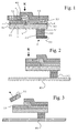
- Figure 5 shows the same as Figure 4, but after removal of the masking tape 3.2 of the adhesive layer 2.2, after which the paper roll is actually accelerated with their adhesive-ready adhesive layer 2.2.
- FIG. 6 shows the moment when the new roll of paper prepared according to FIG. 5 and brought so far to rotational speed n that the web speed of its outermost winding P1, that is to say nx ⁇ ⁇ D, largely coincides with the web speed of the old paper web, reaches end E the old paper web is introduced and pressed, after which it comes to the bonding of both paper webs.
- Figure 7 shows - starting from a web speed of about 120 km / h - about half to one millisecond later tearing open the shutter 5 of the new paper roll with concomitant detachment of the uppermost layer P1 of the new paper roll of the second uppermost layer P2. Thereafter, their following winding layers are removable.
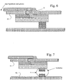
- Figures 8 to 14 relate to the second, most preferred Embodiment and show it in a completely analog sequence. As in the preceding FIGS. 2 to 7, in FIGS. 9 to 14, too, in comparison to FIGS Tape width (preferably 7 cm) slight curvature of the paper windings (Roll diameter about 2 meters) neglected.
- Figure 8 shows an inventive adhesive splicing tape K, which is arranged on its top adhesive surface 2.1 extends across the entire tape width.
- the position "b” has thus moved so far to the right that it comes to lie exactly below the position "d".
- the position "a” is exactly the same as in FIG. 1, at least in the vicinity of the first boundary edge 4.1, preferably - as shown here - precisely on it.
- "d" is at or on the second boundary edge 4.2.
- the second adhesive layer 2.2 of the adhesive tape K extends on the same side of the carrier 1 as the first adhesive layer 2.1. Maintaining the nomenclature of the first example, the first adhesive layer 2.1 extends from position "a" to position "b" and the second adhesive layer 2.2 extends from position "c" to position "d".
- the special feature of the invention is that the position c is closer to the first boundary edge 4.1 than the position b. In other words, in the page assignment chosen in the figures, c is further to the left than b.
- the overlap width is equal to the width of the second one Adhesive layer 2.2.
- Adhesive layer 2.1 has a higher shear resistance than the second, right and overlapping second adhesive layer 2.2, while the latter (2.2) the higher tack should have.
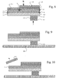
- FIG. 9 shows the same adhesive tape as FIG. 8, but already adhesively bonded to the second uppermost paper ply P2 or winding of the new paper roll by means of the adhesive layer 5.3.
- Figure 10 shows the same as Figure 9, but now already the cover 3.1 is subtracted from the exposable part of the adhesive surface 2.1.
- Figure 12 shows the same as Figure 11, but after removal of the masking tape 3.2 of the adhesive layer 2.2, after which the paper roll is actually accelerated with their adhesive-ready adhesive layer 2.2.
- FIG. 13 the new paper roll prepared according to FIG. 12 has already been brought to a speed n such that its web speed on the outer circumference, that is to say n ⁇ ⁇ ⁇ D, largely coincides with the web speed of the old paper web.
- n such that its web speed on the outer circumference
- This figure shows the moment in which the end E of the old paper web is introduced and pressed, after which it comes to the gluing (the actual splice) with the upper winding P1 of the new paper web.
- Figure 14 shows - starting from a web speed of about 120 km / h - about half to one millisecond later tearing of the shutter 5 between the two peripheral P1 and P2 of the new paper roll. After this closure opening and the following winding layers are removable.
- the invention teaches to better tolerate the inevitable small synchronization deficiencies in the implementation of a flying splice Beginning of the contact of the prepared new railway with the old railway a larger one To build pressure between the two. Such a pressure concentration on The beginning of the adhesion is achieved by superimposing two adhesive layers in reached at least a small overlap area.
- both adhesive layers are made composed of different adhesives, with the first adhesive layer, the is intended to cling to the new role at the beginning (A), to a particularly high level Shear resistance is developed even if this is in competition with the achievable Stickiness stands, while the second adhesive layer, which is intended, at the end of to adhere to the old material web, indicating a higher stickiness is developed.
- An inventive adhesive tape can be produced particularly easily if the first Adhesive layer is applied over the full width of the adhesive tape, while the second only one - seen in the direction of the material web direction to be joined leading - takes up area; then the overlap area of both layers large and identical to the extension area of the second layer.
- the invention serves to further reduce the rate of such Zippers that could be associated with a splice.
Landscapes
- Chemical & Material Sciences (AREA)
- Organic Chemistry (AREA)
- Adhesive Tapes (AREA)
- Replacement Of Web Rolls (AREA)
- Adhesives Or Adhesive Processes (AREA)
Abstract
Description
Klebeband (K) zum Aneinanderfügen zweier Materialbahnen (I, II),
vorzugsweise zum Aneinanderfügen des Anfanges (A) einer neuen Papierrolle (P) an das Ende (E) einer zur Neige gehenden alten Papierrolle,
ist die erfindungsgemäße Lösung dadurch gekennzeichnet, dass
- Fig. 1
- ein erfindungsgemäßes Splice-Klebeband, dessen erste Klebeschicht sich nicht über die gesamte Klebebandbreite erstreckt,
- Fig. 2
- das gleiche Klebeband wie Figur 1, nun aber bereits aufgeklebt auf die zweitoberste Papierlage oder Wicklung der neuen Papierrolle,
- Fig. 3
- das Gleiche wie Figur 2, wobei jedoch nun bereits das Abdeckband von der ersten Klebeschicht abgezogen ist,
- Fig. 4
- das Gleiche wie Figur 3, wobei jedoch nun bereits die oberste Papierlage (= oberste oder letzte Wicklung) der neuen Papierrolle auf den durch das vorherige Abziehen des Abdeckbandes freigelegten Teilbereich der ersten Klebeschicht aufgeklebt ist, wonach die so vorbereitete neue Papierrolle verschlossen und dadurch fliehkraftbeständig ist,
- Fig. 5
- das Gleiche wie Figur 4, jedoch nach Entfernung des Abdeckbandes von der zweiten Klebeschicht, wonach nun die Papierrolle tatsächlich beschleunigt wird,
- Fig. 6
- zeigt den Moment, wo die gemäß Fig. 5 vorbereitete und auf die richtige Drehzahl beschleunigte neue Papierrolle an die alte Papierbahn herangeführt und angedrückt wird, wonach es zur Verklebung beider Papierbahnen kommt, und schließlich zeigt
- Fig. 7
- das etwa eine halbe bis eine Millisekunde später erfolgende Aufreißen des Verschlusses der neuen Papierrolle P, sodass nun auch die folgenden Wickellagen abziehbar sind.
- Fig. 8
- ein erfindungsgemäßes Splice-Klebeband, dessen erste Klebeschicht sich über die gesamte Klebebandbreite erstreckt,
- Fig. 9
- das gleiche Klebeband wie Figur 8, nun aber bereits aufgeklebt auf die zweitoberste Papierlage oder Wicklung der neuen Papierrolle,
- Fig. 10
- das Gleiche wie Figur 9, wobei jedoch nun bereits das Abdeckband von der ersten Klebefläche abgezogen ist,
- Fig. 11
- das Gleiche wie Figur 10, wobei jedoch nun bereits die oberste Papierlage (= oberste oder letzte Wicklung) der neuen Papierrolle auf den durch das vorherige Abziehen des Abdeckbandes freigelegten Teilbereich der ersten Klebefläche aufgeklebt ist, wonach die so vorbereitete neue Papierrolle verschlossen und dadurch fliehkraftbeständig ist,
- Fig. 12
- das Gleiche wie Figur 11, jedoch nach Entfernung des Abdeckbandes von der zweiten Klebeschicht, wonach nun die Papierrolle mit ihrer klebebereiten Klebeschicht tatsächlich beschleunigt wird,
- Fig. 13
- zeigt den Moment, wo die gemäß Fig. 12 vorbereitete und auf die richtige Drehzahl gebrachte neue Papierrolle an die alte Papierbahn herangeführt und angedrückt wird, wonach es zur Verklebung beider Papierbahnen kommt, und schließlich zeigt
- Fig. 14
- das etwa eine halbe bis eine Millisekunde später erfolgende Aufreißen des Verschlusses der neuen Papierrolle P, sodass nun auch die folgenden Wickellagen abziehbar sind.
Unter Beibehalt der Nomenklatur des ersten Beispieles erstreckt sich die erste Klebeschicht 2.1 von Position "a" bis Position "b" und die zweite Klebeschicht 2.2 von Position "c" bis Position "d". Dabei liegt die Besonderheit der Erfindung darin, dass die Position c näher an der ersten Begrenzungskante 4.1 liegt als die Position b. Mit anderen Worten: In der in den Figuren gewählten Seitenzuordnung liegt c weiter links als b.
Figur 9 zeigt das gleiche Klebeband wie Figur 8, nun aber bereits mittels der Klebeschicht 5.3 aufgeklebt auf die zweitoberste Papierlage P2 oder Wicklung der neuen Papierrolle.
- a
- als "erste Position" bezeichnete Stelle zumindest in der Nähe (schließt auch "exakt bei") der ersten Begrenzungskante 4.1 des Trägers 1
- b
- als "zweite Position" bezeichnete Stelle, die näher an der anderen Begrenzungskante 4.2 des Trägers 1 liegt als Position a dies tut; gleichwohl kann b näher an der Begrenzungskante 4.1 liegen als an der Begrenzungskante 4.2; b kann auch auf der Begrenzungskante 4.2 liegen (siehe zweites Ausführungsbeispiel)
- c
- als dritte Position bezeichnete Stelle, die sich zwischen den beiden Begrenzungskanten 4.1 und 4.2 des Trägers 1 des Klebebandes K befindet und gemäß dem Stande der Technik auf b oder weiter zu 4.2 hin, gemäß der Erfindung aber näher an 4.1 als b, was eine Überlappung zweier Klebschichten impliziert
- d
- als vierte Position bezeichnete Stelle, die sich in der Nähe der anderen Begrenzungskante (4.2) des Trägers (1) befindet
- A
- Anfang von P
- E
- Ende einer zur Neige gehenden alten Papierrolle
- K
- Klebeband
- P
- Lagen der neuen Papierrolle, und zwar
- P1
- oberste (oder letzte) Lage der neuen Papierrolle P
- P2
- zweitoberste (oder vorletzte) Lage der neuen Papierrolle P
- I
- erste von zwei aneinander zu fügenden Materialbahnen (von neuer Rolle)
- II
- zweite von zwei aneinander zu fügenden Materialbahnen (von alter Rolle)
- 1
- Träger des Klebebandes
- 2
- Klebeschichten, und zwar
- 2.1
- erste Klebeschicht auf Oberseite des Trägers 1, zur abwickelsicheren Fixierung des Anfanges A der neuen Rolle P
- 2.2
- zweite Klebeschicht auf Oberseite des Trägers 1
- 3
- Abdeckbänder, und zwar
- 3.1
- Abdeckband auf Klebeschicht 2.1
- 3.2
- Abdeckband auf Klebeschicht 2.2
- 3.3
- Abdeckband unter der Klebeschicht 5.3
- 4
- Begrenzungskanten des Trägers 1, nämlich
- 4.1
- erste Begrenzungskante
- 4.2
- zweite Begrenzungskante
- 5
- lösbarer Verschluss der neuen Papierrolle P
- 5.1
- Klebeschicht des lösbaren Verschlusses 5 zur Anbindung an den Träger 1
- 5.2
- Spaltpapier zur Auflösung des Verschlusses 5 und damit der Freigabe der neuen Papierrolle zum Abwickeln
- 5.3
- Klebeschicht des lösbaren Verschlusses 5 zur Anbindung an die zweitoberste Lage P2 der neuen Papierrolle P
Claims (13)
- Klebeband (K) zum Aneinanderfügen zweier Materialbahnen (I, II), insbesondere zum Aneinanderfügen des Anfanges (A) einer neuen Papierrolle (P) an das Ende (E) einer zur Neige gehenden alten Papierrolle,a) wobei das Klebeband (K) dazu geeignet ist, zumindest im Wesentlichen quer über die aneinander zu fügenden Materialbahnen (I, II) aufgeklebt zu werden,b) wobei das Klebeband (K) einen - vorzugsweise aus Papier bestehenden - Träger (1) aufweist,c) auf dessen (1) Oberseite eine erste Klebeschicht (2.1) und eine zweite Klebeschicht (2.2) angeordnet ist,d) wobei die erste Klebeschicht (2.1) dazu vorgesehen ist, am Anfang (= das vordere Ende) der neuen Materialbahn (I) anzuhaften,e) während die zweite Klebeschicht (2.2) dazu vorgesehen ist, am Ende (E) der zur Neige gehenden alten Materialbahn (II) anzuhaften,f) wobei sich die erste Klebeschicht (2.1) - in der Dimension der Breite des Klebebandes - von einer ersten Position (a) in der Nähe einer ersten Begrenzungskante (4.1) des Trägers (1) bis zu einer zweiten Position (b) erstreckt, welche sich zwischen den beiden Begrenzungskanten (4.1, 4.2) des Klebebandes (K) oder an der zweiten Begrenzungskante (4.2) befindet,g) und sich die zweite Klebeschicht (2.2) - in der Dimension der Breite des Klebebandes (K) - von einer dritten Position (c), welche sich zwischen den beiden Begrenzungskanten (4.1, 4.2) des Trägers (1) des Klebebandes (K) befindet bis zu einer vierten Position (d) in der Nähe der anderen Begrenzungskante (4.2) des Trägers (1) erstreckt,
dadurch gekennzeichnet, dassh) die zweite Position (b) weiter von der ersten Begrenzungskante (4.1) des Trägers (1) entfernt liegt als die dritte Position (c),i) sodass die zweite Klebeschicht (2.2) die erste Klebeschicht (2.1) überlappt. - Klebeband (K) nach Anspruch 1, dadurch gekennzeichnet, dass die beiden Klebeschichten (2.1, 2.2) aus verschiedenen Klebmassen bestehen.
- Klebeband (K) nach Anspruch 2, dadurch gekennzeichnet, dass die Klebmasse der ersten Klebeschicht (2.1) eine höhere Scherbeständigkeit aufweist als die Klebmasse der zweiten Klebeschicht (2.2).
- Klebeband (K) nach Anspruch 3, dadurch gekennzeichnet, dass die Scherbeständigkeit der ersten Klebmasse um mindestens 40% über der Scherbeständigkeit der zweiten Klebmasse liegt.
- Klebeband (K) nach Anspruch 4, dadurch gekennzeichnet, dass die Scherbeständigkeit der ersten Klebmasse mindestens das 3-fache, besonders bevorzugt etwa das 15-fache der Scherbeständigkeit der zweiten Klebmasse beträgt.
- Klebeband (K) nach Anspruch 2, dadurch gekennzeichnet, dass die zweite Klebmasse eine höhere Klebrigkeit aufweist als die erste Klebmasse.
- Klebeband (K) nach Anspruch 3, dadurch gekennzeichnet, dass die zweite Klebmasse eine höhere Klebrigkeit aufweist als die erste Klebmasse.
- Klebeband (K) nach Anspruch 6 oder 7, dadurch gekennzeichnet, dass die Klebrigkeit (= Tack) der zweiten Klebmasse um mindestens den Faktor 3, vorzugsweise 8 bis 12 größer ist als die Klebrigkeit der ersten Klebmasse, wobei beide Klebrigkeiten gemäß PSTC-6 zu messen sind bei einer Temperatur von 25°C.
- Klebeband (K) nach einem der vorangehenden Ansprüche, dadurch gekennzeichnet, dass die erste Klebezone nur höchstens 30% der Breite des Klebebandes (K) einnimmt.
- Klebeband (K) nach einem der vorangehenden Ansprüche, dadurch gekennzeichnet, dass im Überlappungsbereich die scherbeständigere Klebeschicht (2.1) unterhalb der weniger scherbeständigen Klebeschicht (2.2) liegt.
- Klebeband (K) nach einem der vorangehenden Ansprüche, dadurch gekennzeichnet, dass im Überlappungsbereich die klebrigere Klebeschicht (2.2) über der weniger klebrigen Klebeschicht (2.1) liegt.
- Klebeband (K) nach einem der vorangehenden Ansprüche, dadurch gekennzeichnet, dass sich die erste Klebeschicht (2.1) über die gesamte Breite des Klebebandes (K) erstreckt.
- Klebeband (K) nach einem der vorangehenden Ansprüche, dadurch gekennzeichnet, dass es eine Breite unterhalb von 35 mm aufweist.
Applications Claiming Priority (2)
| Application Number | Priority Date | Filing Date | Title |
|---|---|---|---|
| DE10258667A DE10258667A1 (de) | 2002-12-13 | 2002-12-13 | Klebeband zum Aneinanderfügen des Anfanges einer neuen Papierrolle an das Ende einer zur Neige gehenden alten Papierrolle |
| DE10258667 | 2002-12-13 |
Publications (3)
| Publication Number | Publication Date |
|---|---|
| EP1428861A2 true EP1428861A2 (de) | 2004-06-16 |
| EP1428861A3 EP1428861A3 (de) | 2004-07-14 |
| EP1428861B1 EP1428861B1 (de) | 2006-03-22 |
Family
ID=32319117
Family Applications (1)
| Application Number | Title | Priority Date | Filing Date |
|---|---|---|---|
| EP03026403A Expired - Lifetime EP1428861B1 (de) | 2002-12-13 | 2003-11-19 | Klebeband zum Aneinanderfügen des Anfanges einer neuen Papierrolle an das Ende einer zur Neige gehenden alten Papierrolle |
Country Status (6)
| Country | Link |
|---|---|
| US (1) | US7086627B2 (de) |
| EP (1) | EP1428861B1 (de) |
| JP (1) | JP2004197089A (de) |
| KR (1) | KR20040052190A (de) |
| CA (1) | CA2450328C (de) |
| DE (2) | DE10258667A1 (de) |
Cited By (2)
| Publication number | Priority date | Publication date | Assignee | Title |
|---|---|---|---|---|
| EP1840063A4 (de) * | 2005-01-17 | 2008-08-27 | Ishida Seisakusho | Filmrolle |
| DE102015222282A1 (de) | 2015-11-12 | 2017-05-18 | Tesa Se | Klebeband und seine Verwendung |
Families Citing this family (14)
| Publication number | Priority date | Publication date | Assignee | Title |
|---|---|---|---|---|
| DE10258667A1 (de) * | 2002-12-13 | 2004-07-08 | Tesa Ag | Klebeband zum Aneinanderfügen des Anfanges einer neuen Papierrolle an das Ende einer zur Neige gehenden alten Papierrolle |
| DE102004040814A1 (de) * | 2004-08-24 | 2006-03-02 | Tesa Ag | Klebeband zur Herstellung einer Splice-Verbindung |
| WO2006039940A1 (en) * | 2004-10-13 | 2006-04-20 | Nitto Europe N.V. | Adhesive tape and method for changing a reel |
| DE102004053189A1 (de) * | 2004-11-04 | 2006-05-11 | Tesa Ag | Verfahren zur Beschichtung von bahnförmigen Substraten mit mindestens zwei Klebstoffen, nach dem Verfahren hergestelltes Klebeband sowie seine Verwendung |
| US20090304998A1 (en) * | 2005-01-17 | 2009-12-10 | Ishida Co., Ltd. | Film roll |
| DE102008021247A1 (de) | 2008-04-28 | 2009-10-29 | Tesa Se | Klebeband für den Rollenwechsel von Flachbahnmaterialien |
| DE102008023020B4 (de) | 2008-05-09 | 2015-05-07 | Tesa Se | Klebeband für die Durchführung eines fliegenden Rollenwechsels |
| DE102008047966A1 (de) | 2008-09-18 | 2010-03-25 | Tesa Se | Repulpierbare Klebmassen |
| US8999098B2 (en) | 2010-02-05 | 2015-04-07 | Orbital Atk, Inc. | Backing for pre-preg material |
| US9321220B2 (en) | 2010-04-13 | 2016-04-26 | Orbital Atk, Inc. | Automated bias-ply preparation device and process |
| EP2674465A1 (de) * | 2012-06-11 | 2013-12-18 | Orafol Europe GmbH | Klebeband für einen fliegenden Rollenwechsel |
| US9949439B2 (en) * | 2013-05-31 | 2018-04-24 | Tama Plastic Industry | Hinged covering for adhesive surface |
| US10457512B2 (en) | 2016-09-19 | 2019-10-29 | New Era Converting Machinery, Inc. | Automatic lapless butt material splice |
| RU2727208C2 (ru) * | 2016-12-12 | 2020-07-21 | Алексей Анатольевич Алексеев | Трехслойная лента и способ ее изготовления |
Family Cites Families (25)
| Publication number | Priority date | Publication date | Assignee | Title |
|---|---|---|---|---|
| US2377971A (en) | 1943-12-15 | 1945-06-12 | Wood Newspaper Mach Corp | Means for use in splicing webs |
| DE1006786B (de) | 1954-09-02 | 1957-04-18 | Agfa Ag | Verschluss von Verpackungen |
| US2920835A (en) | 1954-09-13 | 1960-01-12 | Daily Mirror Newspapers Ltd | Securing tabs for printing paper rolls |
| US3006568A (en) | 1960-03-02 | 1961-10-31 | Crabtree & Sons Ltd R | Adhesive tab |
| DE1267930B (de) | 1964-10-30 | 1968-05-09 | Zerand Corp | Verfahren und Vorrichtung zum Stoss-an-Stoss-Verbinden zweier Materialbahnen |
| DE3834334C2 (de) | 1988-10-08 | 1995-01-19 | Voith Gmbh J M | Bearbeitungseinrichtung zur Vorbereitung des Bahnendes einer Rolle einer Warenbahn |
| FI81997C (fi) | 1989-01-19 | 1991-01-10 | Lindell Ab Oy | Foerfarande och tejp foer sammanfogning av pappersbanor. |
| EP0418527A3 (en) | 1989-09-19 | 1992-01-22 | Man Roland Druckmaschinen Ag | Method to prepare a roll of breadths of print cloth for an automatic reel changer |
| SE466346B (sv) | 1989-12-01 | 1992-02-03 | Jan Olof Norrman | Saett att skarva en loepande materialbana med ett vidhaeftningselement |
| DE4033900C2 (de) | 1990-04-03 | 1995-07-27 | Voith Gmbh J M | Splice-Stelle am Bahnanfang eines Wickels zum Verbinden des Bahnanfangs mit dem Bahnende eines anderen Wickels |
| ATE139747T1 (de) | 1990-04-03 | 1996-07-15 | Voith Gmbh J M | Verfahren zum verbinden des bahnanfanges eines wickels an einer splice-stelle mit dem bahnende einer von einem anderen wickel ablaufenden bahn |
| US5323981A (en) | 1991-12-13 | 1994-06-28 | Sequa Corporation | Splicer tape system |
| DE4210329A1 (de) | 1992-03-30 | 1993-10-07 | Koenig & Bauer Ag | Anordnung zum Verbinden aufeinanderfolgender, zu Rollen gewickelter Papierbahnen |
| NL9300707A (nl) | 1993-04-26 | 1994-11-16 | Knp Papier Bv | Werkwijze voor het lassen van een papierbaan en een kleefstrook ten gebruike bij deze werkwijze. |
| CA2113932A1 (en) | 1993-09-20 | 1995-03-21 | Pierre Caudal | Cleavable release structure |
| EP0757657B1 (de) | 1994-04-26 | 1998-01-07 | Minnesota Mining And Manufacturing Company | Verbindungsklebeband, verfahren zum verbinden und spleiss mit dem verbindungsklebeband |
| GB9420900D0 (en) | 1994-10-17 | 1994-11-30 | Barrett Gary A | Dry peel nose tab |
| DE19544010C2 (de) | 1995-11-27 | 2001-10-04 | Peter Prinz | Etikett für fliegenden Rollenwechsel |
| DE19628317A1 (de) | 1996-07-13 | 1998-01-15 | Beiersdorf Ag | Klebeband und Verfahren zu seiner Verwendung |
| DE19632689A1 (de) | 1996-08-14 | 1998-02-19 | Beiersdorf Ag | Klebeband und Verfahren zu seiner Verwendung |
| DE19830673A1 (de) | 1998-07-09 | 2000-01-13 | Beiersdorf Ag | Klebeband und seine Verwendung |
| DE19830674A1 (de) | 1998-07-09 | 2000-01-13 | Beiersdorf Ag | Klebeband und seine Verwendung |
| DE19902179B4 (de) | 1999-01-21 | 2005-04-28 | Tesa Ag | Klebeband und Spliceverfahren |
| DE10112636B4 (de) | 2001-03-14 | 2006-04-13 | Koenig & Bauer Ag | Verfahren und Vorrichtung zur Klebestellenvorbereitung einer Materialrolle |
| DE10258667A1 (de) * | 2002-12-13 | 2004-07-08 | Tesa Ag | Klebeband zum Aneinanderfügen des Anfanges einer neuen Papierrolle an das Ende einer zur Neige gehenden alten Papierrolle |
-
2002
- 2002-12-13 DE DE10258667A patent/DE10258667A1/de not_active Withdrawn
- 2002-12-17 US US10/321,237 patent/US7086627B2/en not_active Expired - Lifetime
-
2003
- 2003-11-19 EP EP03026403A patent/EP1428861B1/de not_active Expired - Lifetime
- 2003-11-19 DE DE50302721T patent/DE50302721D1/de not_active Expired - Lifetime
- 2003-11-20 CA CA2450328A patent/CA2450328C/en not_active Expired - Fee Related
- 2003-12-05 JP JP2003407583A patent/JP2004197089A/ja active Pending
- 2003-12-12 KR KR1020030090613A patent/KR20040052190A/ko not_active Withdrawn
Cited By (4)
| Publication number | Priority date | Publication date | Assignee | Title |
|---|---|---|---|---|
| EP1840063A4 (de) * | 2005-01-17 | 2008-08-27 | Ishida Seisakusho | Filmrolle |
| DE102015222282A1 (de) | 2015-11-12 | 2017-05-18 | Tesa Se | Klebeband und seine Verwendung |
| EP3173452A1 (de) | 2015-11-12 | 2017-05-31 | tesa SE | Klebeband und seine verwendung |
| US10858209B2 (en) | 2015-11-12 | 2020-12-08 | Tesa Se | Adhesive tape and its use |
Also Published As
| Publication number | Publication date |
|---|---|
| CA2450328A1 (en) | 2004-06-13 |
| KR20040052190A (ko) | 2004-06-22 |
| EP1428861A3 (de) | 2004-07-14 |
| CA2450328C (en) | 2011-11-08 |
| JP2004197089A (ja) | 2004-07-15 |
| DE50302721D1 (de) | 2006-05-11 |
| US20040115427A1 (en) | 2004-06-17 |
| US7086627B2 (en) | 2006-08-08 |
| DE10258667A1 (de) | 2004-07-08 |
| EP1428861B1 (de) | 2006-03-22 |
Similar Documents
| Publication | Publication Date | Title |
|---|---|---|
| EP0831046B1 (de) | Doppelseitiges Klebeband zum Spleissen einer Papierbahn und Verfahren zu seiner Verwendung | |
| DE69407822T2 (de) | Verbindungsklebeband, verfahren zum verbinden und spleiss mit dem verbindungsklebeband | |
| EP0818408B1 (de) | Klebeband und Verfahren zu seiner Herstellung | |
| EP0970905B1 (de) | Klebeband und seine Verwendung | |
| EP1428861B1 (de) | Klebeband zum Aneinanderfügen des Anfanges einer neuen Papierrolle an das Ende einer zur Neige gehenden alten Papierrolle | |
| EP0970904B1 (de) | Klebeband und seine Verwendung | |
| DE69405861T2 (de) | Spleissband, spleissungsverfahren und ein spleiss der dieses band verwendet | |
| DE60120196T2 (de) | Band für fliegendes spleissen, verfahren zur verwendung, und verfahren zur herstellung | |
| EP0566880A1 (de) | Anordnung zum Verbinden aufeinanderfolgender, zu Rollen gewickelter Papierbahnen | |
| EP1355843B1 (de) | Klebeband für den fliegenden rollenwechsel | |
| EP1022245A2 (de) | Klebeband | |
| EP1432631B1 (de) | Maschinell erkennbares klebeband | |
| EP1423321B1 (de) | Maschinell erkennbares klebeband | |
| DE102010029181A1 (de) | Spliceklebeband umfassend zwei spaltfähige Verbindungselemente | |
| EP1436220B1 (de) | Klebeband für das endloskleben am kalander | |
| DE9201286U1 (de) | Fliegender Rollenkleber | |
| EP1630116B1 (de) | Klebeband zur Herstellung einer Splice-Verbindung | |
| EP1640301B1 (de) | Klebeband zur Herstellung einer Verbindung beim fliegenden Rollenwechsel mit einem spaltbaren System | |
| EP1645533B1 (de) | Klebeband zur Herstellung einer Verbindung bei einem statischen Rollenwechsel | |
| DE102004028312A1 (de) | Klebeband und seine Verwendung | |
| EP1340703B1 (de) | Verfahren zur Herstellung einer Rolle eines Flachbahnmaterials | |
| WO2011069824A1 (de) | Verwendung eines splicebandes mit nebeneinander angeordneten kaschiermassestreifen | |
| DE10029298A1 (de) | Befestigungsetikett | |
| EP2859056A1 (de) | Klebeband für einen fliegenden rollenwechsel | |
| DE10201404A1 (de) | Klebeband für den Rollenwechsel und Verwendung eines Klebebands |
Legal Events
| Date | Code | Title | Description |
|---|---|---|---|
| PUAI | Public reference made under article 153(3) epc to a published international application that has entered the european phase |
Free format text: ORIGINAL CODE: 0009012 |
|
| PUAL | Search report despatched |
Free format text: ORIGINAL CODE: 0009013 |
|
| AK | Designated contracting states |
Kind code of ref document: A2 Designated state(s): AT BE BG CH CY CZ DE DK EE ES FI FR GB GR HU IE IT LI LU MC NL PT RO SE SI SK TR |
|
| AX | Request for extension of the european patent |
Extension state: AL LT LV MK |
|
| AK | Designated contracting states |
Kind code of ref document: A3 Designated state(s): AT BE BG CH CY CZ DE DK EE ES FI FR GB GR HU IE IT LI LU MC NL PT RO SE SI SK TR |
|
| AX | Request for extension of the european patent |
Extension state: AL LT LV MK |
|
| 17P | Request for examination filed |
Effective date: 20050114 |
|
| AKX | Designation fees paid |
Designated state(s): DE FI FR GB IT SE |
|
| GRAP | Despatch of communication of intention to grant a patent |
Free format text: ORIGINAL CODE: EPIDOSNIGR1 |
|
| RIN1 | Information on inventor provided before grant (corrected) |
Inventor name: KLEINHOF, KLAUS Inventor name: NAGEL, CHRISTOPH Inventor name: GEBBEKEN, BERNHARD, DR. Inventor name: KEHLER, HARALD, DR. |
|
| GRAS | Grant fee paid |
Free format text: ORIGINAL CODE: EPIDOSNIGR3 |
|
| GRAA | (expected) grant |
Free format text: ORIGINAL CODE: 0009210 |
|
| AK | Designated contracting states |
Kind code of ref document: B1 Designated state(s): DE FI FR GB IT SE |
|
| PG25 | Lapsed in a contracting state [announced via postgrant information from national office to epo] |
Ref country code: IT Free format text: LAPSE BECAUSE OF FAILURE TO SUBMIT A TRANSLATION OF THE DESCRIPTION OR TO PAY THE FEE WITHIN THE PRESCRIBED TIME-LIMIT;WARNING: LAPSES OF ITALIAN PATENTS WITH EFFECTIVE DATE BEFORE 2007 MAY HAVE OCCURRED AT ANY TIME BEFORE 2007. THE CORRECT EFFECTIVE DATE MAY BE DIFFERENT FROM THE ONE RECORDED. Effective date: 20060322 |
|
| REG | Reference to a national code |
Ref country code: GB Ref legal event code: FG4D Free format text: NOT ENGLISH |
|
| REF | Corresponds to: |
Ref document number: 50302721 Country of ref document: DE Date of ref document: 20060511 Kind code of ref document: P |
|
| GBT | Gb: translation of ep patent filed (gb section 77(6)(a)/1977) |
Effective date: 20060510 |
|
| REG | Reference to a national code |
Ref country code: SE Ref legal event code: TRGR |
|
| ET | Fr: translation filed | ||
| PLBE | No opposition filed within time limit |
Free format text: ORIGINAL CODE: 0009261 |
|
| STAA | Information on the status of an ep patent application or granted ep patent |
Free format text: STATUS: NO OPPOSITION FILED WITHIN TIME LIMIT |
|
| 26N | No opposition filed |
Effective date: 20061227 |
|
| REG | Reference to a national code |
Ref country code: FR Ref legal event code: CJ Ref country code: FR Ref legal event code: CD |
|
| REG | Reference to a national code |
Ref country code: FR Ref legal event code: PLFP Year of fee payment: 13 |
|
| REG | Reference to a national code |
Ref country code: DE Ref legal event code: R081 Ref document number: 50302721 Country of ref document: DE Owner name: TESA SE, DE Free format text: FORMER OWNER: TESA SE, 20253 HAMBURG, DE |
|
| REG | Reference to a national code |
Ref country code: FR Ref legal event code: PLFP Year of fee payment: 14 |
|
| REG | Reference to a national code |
Ref country code: FR Ref legal event code: CA Effective date: 20170201 |
|
| REG | Reference to a national code |
Ref country code: FR Ref legal event code: PLFP Year of fee payment: 15 |
|
| REG | Reference to a national code |
Ref country code: DE Ref legal event code: R079 Ref document number: 50302721 Country of ref document: DE Free format text: PREVIOUS MAIN CLASS: C09J0007020000 Ipc: C09J0007200000 |
|
| PGFP | Annual fee paid to national office [announced via postgrant information from national office to epo] |
Ref country code: DE Payment date: 20171121 Year of fee payment: 15 Ref country code: FI Payment date: 20171121 Year of fee payment: 15 Ref country code: FR Payment date: 20171121 Year of fee payment: 15 |
|
| PGFP | Annual fee paid to national office [announced via postgrant information from national office to epo] |
Ref country code: SE Payment date: 20171120 Year of fee payment: 15 Ref country code: IT Payment date: 20171124 Year of fee payment: 15 Ref country code: GB Payment date: 20171123 Year of fee payment: 15 |
|
| REG | Reference to a national code |
Ref country code: DE Ref legal event code: R119 Ref document number: 50302721 Country of ref document: DE |
|
| REG | Reference to a national code |
Ref country code: SE Ref legal event code: EUG |
|
| GBPC | Gb: european patent ceased through non-payment of renewal fee |
Effective date: 20181119 |
|
| PG25 | Lapsed in a contracting state [announced via postgrant information from national office to epo] |
Ref country code: FI Free format text: LAPSE BECAUSE OF NON-PAYMENT OF DUE FEES Effective date: 20181119 Ref country code: SE Free format text: LAPSE BECAUSE OF NON-PAYMENT OF DUE FEES Effective date: 20181120 |
|
| PG25 | Lapsed in a contracting state [announced via postgrant information from national office to epo] |
Ref country code: DE Free format text: LAPSE BECAUSE OF NON-PAYMENT OF DUE FEES Effective date: 20190601 Ref country code: FR Free format text: LAPSE BECAUSE OF NON-PAYMENT OF DUE FEES Effective date: 20181130 Ref country code: IT Free format text: LAPSE BECAUSE OF NON-PAYMENT OF DUE FEES Effective date: 20181119 |
|
| PG25 | Lapsed in a contracting state [announced via postgrant information from national office to epo] |
Ref country code: GB Free format text: LAPSE BECAUSE OF NON-PAYMENT OF DUE FEES Effective date: 20181119 |