EP1428720A2 - Système d'appui-tête articulé - Google Patents
Système d'appui-tête articulé Download PDFInfo
- Publication number
- EP1428720A2 EP1428720A2 EP03028238A EP03028238A EP1428720A2 EP 1428720 A2 EP1428720 A2 EP 1428720A2 EP 03028238 A EP03028238 A EP 03028238A EP 03028238 A EP03028238 A EP 03028238A EP 1428720 A2 EP1428720 A2 EP 1428720A2
- Authority
- EP
- European Patent Office
- Prior art keywords
- support
- pawl
- gear segment
- headrest
- teeth
- Prior art date
- Legal status (The legal status is an assumption and is not a legal conclusion. Google has not performed a legal analysis and makes no representation as to the accuracy of the status listed.)
- Withdrawn
Links
- 230000033001 locomotion Effects 0.000 claims description 20
- 230000000994 depressogenic effect Effects 0.000 description 3
- 230000004913 activation Effects 0.000 description 2
- 230000000295 complement effect Effects 0.000 description 2
- 230000033228 biological regulation Effects 0.000 description 1
- 239000006260 foam Substances 0.000 description 1
- 230000014759 maintenance of location Effects 0.000 description 1
Images


Classifications
-
- B—PERFORMING OPERATIONS; TRANSPORTING
- B60—VEHICLES IN GENERAL
- B60N—SEATS SPECIALLY ADAPTED FOR VEHICLES; VEHICLE PASSENGER ACCOMMODATION NOT OTHERWISE PROVIDED FOR
- B60N2/00—Seats specially adapted for vehicles; Arrangement or mounting of seats in vehicles
- B60N2/80—Head-rests
- B60N2/806—Head-rests movable or adjustable
- B60N2/838—Tiltable
- B60N2/841—Tiltable characterised by their locking devices
- B60N2/844—Release mechanisms, e.g. buttons
-
- B—PERFORMING OPERATIONS; TRANSPORTING
- B60—VEHICLES IN GENERAL
- B60N—SEATS SPECIALLY ADAPTED FOR VEHICLES; VEHICLE PASSENGER ACCOMMODATION NOT OTHERWISE PROVIDED FOR
- B60N2/00—Seats specially adapted for vehicles; Arrangement or mounting of seats in vehicles
- B60N2/80—Head-rests
- B60N2/806—Head-rests movable or adjustable
- B60N2/809—Head-rests movable or adjustable vertically slidable
- B60N2/812—Head-rests movable or adjustable vertically slidable characterised by their locking devices
- B60N2/815—Release mechanisms, e.g. buttons
Definitions
- the present invention generally relates to an Articulated Head Restraint System that is part of an automobile.
- a typical headrest consists of a notched rod that may be straight or bent in a "U" shape and held in the car seat's guide tube. Foam and trim covers are placed on top of the rod (the headrest assembly) to give head and neck support and passenger comfort. The notches placed along the length of the rod help in moving the headrest assembly up and down, and locking the headrest in a specific place depending upon the occupant's height.
- the headrests that move fore and aft are typically of a riveted design (4-way).
- the headrest is made in two parts:
- the upper section has welded brackets and a pair of notched rods.
- the rods are attached to the upper section with rivets and a friction pack comprising a wave washer, a flat washer and a rubber or plastic washer.
- the upper section pivots on the pair of rods at riveted joints.
- the upper section is foamed and trimmed for the headrest. The friction on the riveted joints control the movement of the upper section with respect to the lower notched rods.
- headrests are becoming a part of the overall safety restraint system in the vehicles, and are being used as a protection device for whiplash in case of an accident. This requires the headrest to lock in a specific position and not move (at least in the aft direction) unless an activation device is used to move it from one position to another.
- the present invention provides a head restraint system that overcomes some of the above-described problems of the related art.
- the invention allows the occupant to lock the headrest in a specific position.
- the headrest can be moved forward with minimal effort, while moving the headrest in the opposite direction requires a pushbutton activation.
- the invention also combines up and down motions and eliminates the effort issues related to seat frame dimensional tolerances.
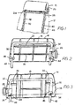
- FIG. 1 illustrates an adjustable headrest 10 mounted on a vehicle seat back 12, illustrated in phantom.
- headrest 10 includes a back cover 14 fastened to a front cover 16.
- the two covers have edges formed together to form a hollow headrest housing.
- a U-shaped tubular upper support member 18 is captured between the front and rear covers in ridge means 20 and 22, respectively. When the two covers are joined together, they combine to form a pair of lower slots 24 and 26.
- the two covers also combine to form a side button opening 28. Support member 18 is fixed to and moves with the two covers.
- Support member 18 has a pair of parallel brackets 30 and 32. The lower ends of the two brackets have rivet-receiving openings 34 and 36, aligned along a pivotal axis 38.
- a pair of upright parallel legs 40 and 42 have upper flattened ends connected by rivet means 44 and 46 to the lower ends of brackets 32 and 30, respectively.
- the headrest pivots about the upper end of legs 40 and 42 about axis 38.
- legs 40 and 42 are received in sockets 48 and 50 in the seat back, locked against horizontal motion.
- the upper ends of legs 40 and 42 extend through slots 24 and 26 to permit the headrest to swing forwardly and rearwardly with respect to the seat back.
- a gear segment 52 is integrally attached to the upper end of leg 40 and has, for illustrative purposes, six teeth 54 spaced in an arc about axis 38.
- Pawl 56 is slidably mounted on bracket 32.
- the pawl has a pair of teeth 58 engageable with teeth 54 on the gear segment.
- the pawl is slidable along the longitudinal axis of bracket 32 between a lower locking position, illustrated in Figures 5 and 7, in which teeth 58 engage teeth 54 to lock the headrest against rearward pivotal motion, and an upper release position, illustrated in Figure 6, in which the pawl is separated from the gear segment teeth to permit the headrest to pivot rearwardly about the seat back.
- the gear segment teeth are so formed as to permit the pawl to ratchet around the gear segment when the headrest is moved forwardly, but to lock the pawl in engagement with the gear segment against rearward motion unless a pushbutton, to be described, is depressed.
- bracket 32 has an internal abutment 60.
- a helical spring 62 mounted between the upper end of the pawl and abutment 60, biases the pawl towards its locking position with the gear segment.
- the pawl has a cam surface 64 facing toward cam button opening 28.
- a button housing 66 is tightly mounted in button opening 28. Housing 66 is hollow and slidably supports a pushbutton 68 in an internal bore 70, as shown in Figure 16.
- the pushbutton has a pair of prongs 72 and 74 and a central tongue 76.
- the tongue has a flat cam surface 78 which is slidably engaged with a complementary, flat cam surface 64 in a notch in the pawl.
- a return spring 80 mounted in the button housing biases the pushbutton toward a locking position in which cam 78 slides on cam 64 so the pawl teeth 58 fully engage teeth 54 on the gear segment.
- the user readjusts the headrest by either pushing the headrest forwardly, or by pushing the pushbutton to release the pawl from the gear segment to swing the headrest toward a rearward position, and then releases the pushbutton to lock the headrest in its adjusted position.
- Figures 8-11 show another embodiment of the invention in which headrest 90 is vertically adjustable on a pair of posts 92 and 94 that extend above the top of the vehicle seat back. Outer covers 14 and 16 are removed for clarity. This design allows vertical adjustment of the headrest on posts 92 and 94. This design also allows the headrest to pivot as well as move vertically on posts 92 and 94.
- Post 92 has a series of vertically and evenly spaced notches 96.
- a pair of support blocks 98 and 100 have through holes 102 and 104 slidably mounted on posts 92 and 94 for up and down motion.
- a U-shaped support member 106 has a pair of legs 108 and 110 pivotally mounted on support blocks 98 and 100. Pivot brackets 114 and 115 are welded to the lower ends of support legs 108 and 110, respectively. Each bracket is mounted in a slot in its respective support block. The lower end of the two support brackets are pivotally mounted on their respective support blocks by rivets 117a and 117b.
- Figures 9 and 10 show a button housing 118 mounted on the hollow headrest housing, not shown.
- a pushbutton 120 is slidably mounted in the button housing so as to be moveable either toward or away from bracket 114.
- the pushbutton has a frusto-conical cam surface 124, which slidably engages a complementary cam surface 126, carried on pawl 128.
- Pawl 128, is vertically slidably mounted on bracket 114, and has locking teeth means 130, for engaging teeth 132, of a gear segment 134, Figure 11.
- Pushing button 120 separates the pawl from the gear segment to permit the headrest to pivot about rivet 116.
- the pushbutton cam surface 124 engages a vertical adjustment detent 136.
- the detent pivots counter-clockwise, about pin 137 so that a tooth 137a disengages a vertical adjustment notch 96 on post 92.
- a leaf spring 138 held in the headrest housing, not shown, keeps constant pressure urging the detent toward post 92 so that when pushbutton 120 is released, the detent can snap into a notch 96 on bar 92.
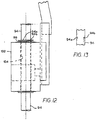
- Figures 12 and 13 show a view of support block 100, which has lateral movement in hole 104.
- Post 94 has two grooves 94A and 94B for retention in block 100, along with a spring 99, which maintains a constant pressure on block 100, in the event that there is any centerline variation in the seat back assembly.
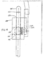
- Figure 14 shows another embodiment of the design to accommodate any variation of the centerline in the seatback assembly.
- Support block 150 has a bore 152 which receives post 94. Bore 152 has a larger diameter than the post so block 150 is laterally movable on the post.
- Ball 154 has a hole 156 that has a slip fit to post 94.
- Block 150 has a lateral hole 158 which receives ball 154 so that the post is able to move laterally and angularly in block 150.
- a spring 160 placed between ball 154, and a rivet 162 in bore hole 158 keeps constant pressure of the ball on post 94.
- Post 94 has a groove 162 for receiving a locking clip, not shown, to hold post 94 in the headrest.
- the safety features of this design are such that the headrest will lock in the set position and will not rotate or pivot back away from the driver's head, or drop lower down into the seat unless the pushbutton is depressed.
Landscapes
- Engineering & Computer Science (AREA)
- Aviation & Aerospace Engineering (AREA)
- Transportation (AREA)
- Mechanical Engineering (AREA)
- Chair Legs, Seat Parts, And Backrests (AREA)
- Seats For Vehicles (AREA)
Applications Claiming Priority (2)
| Application Number | Priority Date | Filing Date | Title |
|---|---|---|---|
| US313809 | 1981-10-22 | ||
| US10/313,809 US6910740B2 (en) | 2002-12-09 | 2002-12-09 | Articulated headrestraint system |
Publications (2)
| Publication Number | Publication Date |
|---|---|
| EP1428720A2 true EP1428720A2 (fr) | 2004-06-16 |
| EP1428720A3 EP1428720A3 (fr) | 2005-03-16 |
Family
ID=32325883
Family Applications (1)
| Application Number | Title | Priority Date | Filing Date |
|---|---|---|---|
| EP03028238A Withdrawn EP1428720A3 (fr) | 2002-12-09 | 2003-12-09 | Système d'appui-tête articulé |
Country Status (4)
| Country | Link |
|---|---|
| US (1) | US6910740B2 (fr) |
| EP (1) | EP1428720A3 (fr) |
| CA (1) | CA2444110A1 (fr) |
| MX (1) | MXPA03011420A (fr) |
Cited By (2)
| Publication number | Priority date | Publication date | Assignee | Title |
|---|---|---|---|---|
| DE102006049053B3 (de) * | 2006-10-13 | 2008-03-27 | A. Raymond Et Cie | Betätigungsvorrichtung für eine in Längsrichtung zu verschiebende Fixierstange |
| CN104842832A (zh) * | 2015-05-19 | 2015-08-19 | 沈阳金杯江森自控汽车内饰件有限公司 | 新型汽车座椅头枕旋转调节系统 |
Families Citing this family (39)
| Publication number | Priority date | Publication date | Assignee | Title |
|---|---|---|---|---|
| US6983989B1 (en) | 2004-09-24 | 2006-01-10 | Lear Corporation | Linear adjustable active head restraint |
| US7140687B2 (en) * | 2004-11-18 | 2006-11-28 | Fisher Dynamics Corporation | Spring-loaded headrest |
| US7185950B2 (en) * | 2004-12-28 | 2007-03-06 | Fisher Dynamics Corporation | Head restraint system |
| US20060138817A1 (en) * | 2004-12-29 | 2006-06-29 | Gorman Patrick J | Energy absorbing seat recliner assembly |
| US20060226686A1 (en) * | 2005-03-22 | 2006-10-12 | Shihong Yu | Spinal protection system for automotive seat |
| US7441821B2 (en) * | 2005-11-21 | 2008-10-28 | Lear Corporation | System and method for actuation of a head restraint |
| DE102006054166B4 (de) * | 2005-11-21 | 2009-07-30 | Lear Corp., Southfield | System und Verfahren zum Betätigen einer Kopfstütze |
| JP4580337B2 (ja) * | 2005-12-26 | 2010-11-10 | 日本発條株式会社 | ヘッドレストブッシュ及びそれを用いた車両用シート |
| US20070164593A1 (en) * | 2006-01-17 | 2007-07-19 | Windsor Machine & Stamping Limited | Articulating headrest assembly |
| US7431400B2 (en) * | 2006-01-20 | 2008-10-07 | Christopher J. Vitito | Tilting mechanism for automobile headrests |
| US7669932B1 (en) * | 2006-02-28 | 2010-03-02 | Grammer A.G. | Headrest |
| US20080030061A1 (en) * | 2006-08-04 | 2008-02-07 | Srinivas Pejathaya | Multi-position adjustment mechanism |
| US20080203801A1 (en) * | 2007-02-28 | 2008-08-28 | Lear Corporation | Folding head restraint mechanism |
| US20090001792A1 (en) * | 2007-06-29 | 2009-01-01 | Lear Corporation | Head restraint system for a vehicle seat |
| US7871129B2 (en) * | 2007-12-05 | 2011-01-18 | Lear Corporation | Seat assembly having an adjustable head restraint assembly |
| US7758126B2 (en) * | 2008-01-10 | 2010-07-20 | Honda Motor Co., Ltd. | Folding headrest |
| US8600624B2 (en) * | 2008-03-29 | 2013-12-03 | Lear Corporation | Method of matching component for vehicle head restraint actuation system |
| US20110089738A1 (en) * | 2008-07-19 | 2011-04-21 | Jen Li-Wen | Headrest Set for Office Chair |
| DE102009020117B4 (de) * | 2009-05-06 | 2013-11-14 | Lear Corp. | Sitzanordnung und verstellbare Kopfstützenanordnung |
| US8177296B2 (en) * | 2009-08-25 | 2012-05-15 | Ruoey Lung Enterprise Corp. | Motorized rocking chair moved in a pendulum manner |
| DE102010030967B4 (de) * | 2010-07-06 | 2012-10-25 | Lear Corp. | Sitzanordnung mit Druckknopfanordnung |
| US8807653B2 (en) * | 2010-09-17 | 2014-08-19 | Lear Corporation | Adjustable head restraint assembly for vehicle seats |
| DE102010041941A1 (de) * | 2010-10-04 | 2012-04-05 | Lear Corporation | Bewegliche Kopfstützen für Fahrzeugsitze |
| US20130134761A1 (en) * | 2011-11-28 | 2013-05-30 | Lear Corporation | Adjustable head restraint assembly for vehicle seats |
| US8979203B1 (en) * | 2012-04-24 | 2015-03-17 | Gill Industries, Inc. | Head restraint assembly |
| US8820839B1 (en) * | 2012-04-24 | 2014-09-02 | Gill Industries, Inc. | Head restraint assembly |
| US8950815B2 (en) * | 2012-11-29 | 2015-02-10 | Daimay North America Automotive, Inc. | Four-way adjustable headrest |
| US20140203615A1 (en) * | 2013-01-22 | 2014-07-24 | Windsor Machine & Stamping, Ltd | Head restraint assembly for a vehicle |
| KR101383094B1 (ko) | 2013-02-20 | 2014-04-08 | 주식회사 우보테크 | 헤드레스트 이동장치 |
| US9132756B1 (en) * | 2013-03-14 | 2015-09-15 | Gill Industries, Inc. | Head restraint assemblies |
| US9409503B2 (en) * | 2014-02-14 | 2016-08-09 | Windsor Machine and Stamping (2009) Ltd. | Ratcheting vehicle head restraint assembly |
| US9475415B2 (en) * | 2014-03-18 | 2016-10-25 | Bae Industries, Inc. | Headrest dump assembly with both cable and push button actuation |
| KR101570427B1 (ko) | 2014-07-11 | 2015-11-19 | 주식회사 우보테크 | 헤드레스트 이동장치 |
| US9308998B1 (en) * | 2015-01-05 | 2016-04-12 | Ami Industries, Inc. | Removable aircraft headrest |
| DE102015200553B4 (de) * | 2015-01-15 | 2022-07-21 | Adient Luxembourg Holding S.À R.L. | Verfahren zur Herstellung einer Kopfstütze |
| JP6488155B2 (ja) * | 2015-03-06 | 2019-03-20 | 株式会社タチエス | ヘッドレスト |
| JP6002809B2 (ja) * | 2015-05-14 | 2016-10-05 | テイ・エス テック株式会社 | ヘッドレスト |
| KR102091220B1 (ko) | 2018-10-04 | 2020-03-19 | 주식회사 우보테크 | 헤드레스트 락킹장치 |
| CN214711596U (zh) * | 2020-12-31 | 2021-11-16 | 张孝兆 | 头枕装置及具有该装置的座椅 |
Citations (3)
| Publication number | Priority date | Publication date | Assignee | Title |
|---|---|---|---|---|
| US4830434A (en) | 1986-06-28 | 1989-05-16 | Aisin Seiki Kabushiki Kaisha | Adjustable head rest device for vehicle |
| US5669668A (en) | 1995-08-03 | 1997-09-23 | General Motors Corporation | Folding headrest in particular for motor vehicles |
| US6045181A (en) | 1998-03-18 | 2000-04-04 | Ikeda Bussan Co., Ltd. | Adjustable headrest |
Family Cites Families (9)
| Publication number | Priority date | Publication date | Assignee | Title |
|---|---|---|---|---|
| US4674792A (en) * | 1985-06-07 | 1987-06-23 | Ikeda Bussan Co, Ltd. | Position adjustable see-through headrest |
| DE3605774A1 (de) * | 1986-02-22 | 1987-09-17 | Opel Adam Ag | Umlegbare kopfstuetze fuer einen fahrzeugsitz, insbesondere fuer einen ruecksitz eines personenwagens |
| US4674797A (en) * | 1986-03-25 | 1987-06-23 | Ikeda Bussan Co., Ltd. | Angular position adjustable headrest |
| US5006771A (en) * | 1990-04-10 | 1991-04-09 | Tachi-S Co., Ltd. | Method and device for controlling headrest |
| US5003240A (en) * | 1990-04-10 | 1991-03-26 | Tachi-S Co., Ltd. | Method and device for controlling headrest |
| US5590933A (en) * | 1995-03-30 | 1997-01-07 | Lear Seating Corporation | Folding headrest |
| SE510097C2 (sv) * | 1995-09-29 | 1999-04-19 | Volvo Ab | Omställbart nackskydd |
| US6129421A (en) * | 1999-08-05 | 2000-10-10 | Lear Corporation | Foldable halo style headrest |
| DE10012973B4 (de) * | 2000-03-16 | 2004-02-26 | Daimlerchrysler Ag | Kopfstütze für einen Fahrzeugsitz |
-
2002
- 2002-12-09 US US10/313,809 patent/US6910740B2/en not_active Expired - Fee Related
-
2003
- 2003-10-01 CA CA002444110A patent/CA2444110A1/fr not_active Abandoned
- 2003-12-09 EP EP03028238A patent/EP1428720A3/fr not_active Withdrawn
- 2003-12-09 MX MXPA03011420A patent/MXPA03011420A/es unknown
Patent Citations (3)
| Publication number | Priority date | Publication date | Assignee | Title |
|---|---|---|---|---|
| US4830434A (en) | 1986-06-28 | 1989-05-16 | Aisin Seiki Kabushiki Kaisha | Adjustable head rest device for vehicle |
| US5669668A (en) | 1995-08-03 | 1997-09-23 | General Motors Corporation | Folding headrest in particular for motor vehicles |
| US6045181A (en) | 1998-03-18 | 2000-04-04 | Ikeda Bussan Co., Ltd. | Adjustable headrest |
Cited By (3)
| Publication number | Priority date | Publication date | Assignee | Title |
|---|---|---|---|---|
| DE102006049053B3 (de) * | 2006-10-13 | 2008-03-27 | A. Raymond Et Cie | Betätigungsvorrichtung für eine in Längsrichtung zu verschiebende Fixierstange |
| US7992940B2 (en) | 2006-10-13 | 2011-08-09 | A. Raymond Et Cie | Actuating device for a fixing rod to be displaced in the longitudinal direction |
| CN104842832A (zh) * | 2015-05-19 | 2015-08-19 | 沈阳金杯江森自控汽车内饰件有限公司 | 新型汽车座椅头枕旋转调节系统 |
Also Published As
| Publication number | Publication date |
|---|---|
| MXPA03011420A (es) | 2004-06-18 |
| US6910740B2 (en) | 2005-06-28 |
| EP1428720A3 (fr) | 2005-03-16 |
| CA2444110A1 (fr) | 2004-06-09 |
| US20040108766A1 (en) | 2004-06-10 |
Similar Documents
| Publication | Publication Date | Title |
|---|---|---|
| US6910740B2 (en) | Articulated headrestraint system | |
| US8807653B2 (en) | Adjustable head restraint assembly for vehicle seats | |
| US6192565B1 (en) | Automotive seat assembly having a rectractable headrest | |
| US4511180A (en) | Headrest in passenger cars | |
| US7484808B2 (en) | Vision improving system for a head restraint | |
| EP1397269B1 (fr) | Siege a bonne accessibilite avec verrou de plancher solidaire du dossier | |
| US6749256B1 (en) | Vehicle seat having a movable head restraint | |
| US8056954B2 (en) | Fold flat seat assembly with drive link | |
| US6302485B1 (en) | Head rest device for vehicles | |
| US6616235B1 (en) | Seat assembly with integral head/neck rest | |
| US20010040396A1 (en) | Head rest for a vehicle seat | |
| US5700055A (en) | Seat back automatic height adjustor and recliner mechanism | |
| EP1539534B1 (fr) | Ensemble siege pliable a deplacement lateral principal | |
| JP2006526535A5 (fr) | ||
| US7717508B2 (en) | Headrest with carrier structure and supporting member | |
| JP2007513817A (ja) | 自動車シート用のレール長手方向ガイドに対するメモリ装置 | |
| US9132756B1 (en) | Head restraint assemblies | |
| US20030042781A1 (en) | Neck rest for a seat for automobiles | |
| EP1470023B1 (fr) | Siege de vehicule comprenant un appuie-tete independant du dossier | |
| US6698835B2 (en) | Seat support mechanism of vehicles | |
| US6840560B2 (en) | Vehicular seat assembly having a movable headrest and a vehicle which incorporates the vehicular seat assembly | |
| CN107985151B (zh) | 车辆座椅和用于车辆座椅的头枕 | |
| US7862114B2 (en) | Seat restraining device | |
| JP2001163101A (ja) | 車両用シートのヘッドレスト構造 | |
| EP1167116A1 (fr) | Dossier de siège de véhicule |
Legal Events
| Date | Code | Title | Description |
|---|---|---|---|
| PUAI | Public reference made under article 153(3) epc to a published international application that has entered the european phase |
Free format text: ORIGINAL CODE: 0009012 |
|
| AK | Designated contracting states |
Kind code of ref document: A2 Designated state(s): AT BE BG CH CY CZ DE DK EE ES FI FR GB GR HU IE IT LI LU MC NL PT RO SE SI SK TR |
|
| AX | Request for extension of the european patent |
Extension state: AL LT LV MK |
|
| PUAL | Search report despatched |
Free format text: ORIGINAL CODE: 0009013 |
|
| AK | Designated contracting states |
Kind code of ref document: A3 Designated state(s): AT BE BG CH CY CZ DE DK EE ES FI FR GB GR HU IE IT LI LU MC NL PT RO SE SI SK TR |
|
| AX | Request for extension of the european patent |
Extension state: AL LT LV MK |
|
| AKX | Designation fees paid | ||
| REG | Reference to a national code |
Ref country code: DE Ref legal event code: 8566 |
|
| STAA | Information on the status of an ep patent application or granted ep patent |
Free format text: STATUS: THE APPLICATION IS DEEMED TO BE WITHDRAWN |
|
| 18D | Application deemed to be withdrawn |
Effective date: 20050917 |