EP1427552B1 - Device for forming thin-walled material into a sleeve-shaped body - Google Patents
Device for forming thin-walled material into a sleeve-shaped body Download PDFInfo
- Publication number
- EP1427552B1 EP1427552B1 EP02772206A EP02772206A EP1427552B1 EP 1427552 B1 EP1427552 B1 EP 1427552B1 EP 02772206 A EP02772206 A EP 02772206A EP 02772206 A EP02772206 A EP 02772206A EP 1427552 B1 EP1427552 B1 EP 1427552B1
- Authority
- EP
- European Patent Office
- Prior art keywords
- forming
- centring
- strut
- shaping dies
- dies
- Prior art date
- Legal status (The legal status is an assumption and is not a legal conclusion. Google has not performed a legal analysis and makes no representation as to the accuracy of the status listed.)
- Expired - Lifetime
Links
Images
Classifications
-
- B—PERFORMING OPERATIONS; TRANSPORTING
- B21—MECHANICAL METAL-WORKING WITHOUT ESSENTIALLY REMOVING MATERIAL; PUNCHING METAL
- B21C—MANUFACTURE OF METAL SHEETS, WIRE, RODS, TUBES, PROFILES OR LIKE SEMI-MANUFACTURED PRODUCTS OTHERWISE THAN BY ROLLING; AUXILIARY OPERATIONS USED IN CONNECTION WITH METAL-WORKING WITHOUT ESSENTIALLY REMOVING MATERIAL
- B21C37/00—Manufacture of metal sheets, rods, wire, tubes, profiles or like semi-manufactured products, not otherwise provided for; Manufacture of tubes of special shape
- B21C37/06—Manufacture of metal sheets, rods, wire, tubes, profiles or like semi-manufactured products, not otherwise provided for; Manufacture of tubes of special shape of tubes or metal hoses; Combined procedures for making tubes, e.g. for making multi-wall tubes
- B21C37/08—Making tubes with welded or soldered seams
- B21C37/0815—Making tubes with welded or soldered seams without continuous longitudinal movement of the sheet during the bending operation
-
- B—PERFORMING OPERATIONS; TRANSPORTING
- B21—MECHANICAL METAL-WORKING WITHOUT ESSENTIALLY REMOVING MATERIAL; PUNCHING METAL
- B21D—WORKING OR PROCESSING OF SHEET METAL OR METAL TUBES, RODS OR PROFILES WITHOUT ESSENTIALLY REMOVING MATERIAL; PUNCHING METAL
- B21D5/00—Bending sheet metal along straight lines, e.g. to form simple curves
- B21D5/01—Bending sheet metal along straight lines, e.g. to form simple curves between rams and anvils or abutments
- B21D5/015—Bending sheet metal along straight lines, e.g. to form simple curves between rams and anvils or abutments for making tubes
Definitions
- the invention relates to a device for deforming thin-walled material, from a substantially flat piece of material to a sleeve-shaped body, with two forming dies, at least one of which is arranged movable against the other, wherein at least one of the forming dies is pivotally mounted.
- DE-C-870 540 a device for deforming thin-walled material, from a substantially flat piece of material to a sleeve-shaped body, with two forming dies, one of which is movably arranged against the other, and wherein both forming dies are pivotally mounted known ,
- the invention has the object of providing a device of the type mentioned in such a way that the deformation can be done in a single operation.
- This object is achieved in that in the open state of the forming die pair of the clear distance is so large that the flat-lying piece of material between the two forming dies can be inserted, and that at the pivot of the forming dies facing the end of the two forming dies each intersecting fingers are arranged, and that a centering blade is arranged at the end remote from the pivot end of the two molding dies.
- the board can create the fingers when bending, although the two form matrices do not yet lie against one another. Dodge of the sheet in the space below the molding dies is thus excluded.
- a likewise very advantageous embodiment of the invention is given by the fact that the centering blade is pivotally mounted.
- each of the two Zentrierheter swung out of the mold and the two form matrices are pivoted together in their final position in which the body receives its final shape.
- the centering is pivotally mounted on a two-armed lever, at the side facing away from the centering lever arm a cam or the like. attacks.
- a further advantageous embodiment of the invention is characterized in that preferably a removable closure part is provided adjacent to the centering blade.
- the two closure members are removed from the forming dies, creating an open gap through which the weld can be made to close the body.
- the closure member is mounted longitudinally displaceable.
- This longitudinal displacement is particularly easy to perform.
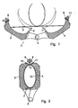
- the device 1 denotes a device in FIG. 1, which device is used for forming a sheet metal blank 2 into a shaped body 20.
- the device 1 contains two molding dies 3 and 4 whose hollow shape corresponds to the outer shape of the later molding 20.
- the two forming dies 3, 4 are pivotably mounted about a common fulcrum 5, wherein it is quite possible to pivotally mount only one of the two forming dies and to arrange the other in a fixed manner.
- the two forming matrices 3, 4 are each equipped with a plurality of fingers 6 and 7, respectively, which grip against one another when the two forming matrices pivot against one another.
- a centering blade 8 or 9 is respectively arranged, against which the respective end of the sheet metal blank 2 is able to bear.
- the respective end of the sheet metal blank 2 moves against this centering blade 8 or 9 and the sheet metal blank 2 is bent into the female mold as indicated in FIG.
- the fingers 6 and 7 prevent that the central portion of the sheet metal blank 2 can escape downwards, as long as the lower ends of the two form matrices do not yet abut each other.
- the two forming dies are closed so far that the centering blades abut each other, they are pulled upwards and the two forming dies are completely attached to each other.
- the device 1 is shown in the almost closed state, wherein the Zentrierratiter 8.9 and the closure parts 10,11 are extended.
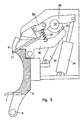
- FIG 3 shows the upper portion of a forming die 4 with the centering blade 9 and the closure member 11 mounted thereon on a larger scale.
- the centering blade 9 is fixed to a pivotally mounted lever 30 which is actuated by a cam 31 which is mounted on a rotatable disc 32. At this cam 31 engages a piston 33, which generates the rotational movement of the disc 32 and thus the pivotal movement of the lever 30.
- Another piston 34 engages a plurality of levers 35 and 36 on the closure member 11 and moves it from its closed position to its open position and vice versa.
- the lever 30 of the Zentrierhetes can still - as indicated - a spring 37 attack, which moves the lever in the retracted position of the Zentrierhistes.
Landscapes
- Engineering & Computer Science (AREA)
- Mechanical Engineering (AREA)
- Bending Of Plates, Rods, And Pipes (AREA)
- Shaping Metal By Deep-Drawing, Or The Like (AREA)
- Forging (AREA)
- Moulds For Moulding Plastics Or The Like (AREA)
- Dowels (AREA)
- Switches That Are Operated By Magnetic Or Electric Fields (AREA)
- Extrusion Moulding Of Plastics Or The Like (AREA)
Abstract
Description
Die Erfindung betrifft eine Vorrichtung zum Verformen von dünnwandigem Material, aus einem im wesentlichen flachliegenden Materialstück zu einem hülsenförmigen Körper, mit zwei Formmatrizen, von denen wenigstens eine gegen die andere bewegbar angeordnet ist, wobei wenigstens eine der Formmatrizen schwenkbar gelagert ist.The invention relates to a device for deforming thin-walled material, from a substantially flat piece of material to a sleeve-shaped body, with two forming dies, at least one of which is arranged movable against the other, wherein at least one of the forming dies is pivotally mounted.
Beim Umformen von Blech zu einem runden oder ovalen Körper wird meist zuerst das flachliegende Blech od.dgl. gerollt und dann in einer Form zum fertigen Körper weiter umgeformt.When reshaping sheet metal to a round or oval body is usually the flat plate or the like first. rolled and then further transformed in a mold to the finished body.
Aus der DE 197 43 436 ist beispielsweise eine derartige Vorrichtung bekannt, die sich zum Umformen großer Stückzahlen sehr gut eignet.From DE 197 43 436, for example, such a device is known, which is very well suited for forming large numbers.
Aus der DE-C-870 540 ist eine Vorrichtung zum Verformen von dünnwandigem Material, aus einem im wesentlichen flachliegenden Materialstück zu einem hülsenförmigen Körper, mit zwei Formmatrizen, von denen eine gegen die andere bewegbar angeordnet ist, und wobei beide Formmatrizen schwenkbar gelagert sind bekannt.From DE-C-870 540 a device for deforming thin-walled material, from a substantially flat piece of material to a sleeve-shaped body, with two forming dies, one of which is movably arranged against the other, and wherein both forming dies are pivotally mounted known ,
Der Erfindung liegt die Aufgabe zugrunde, eine Vorrichtung der genannten Art so auszugestalten, daß die Umformung in einem einzigen Arbeitsgang erfolgen kann.The invention has the object of providing a device of the type mentioned in such a way that the deformation can be done in a single operation.
Diese Aufgabe wird erfindungsgemäß dadurch gelöst, daß im geöffneten Zustand des Formmatrizenpaares der lichte Abstand so groß ist, daß das flachliegende Materialstück zwischen die beiden Formmatrizen einlegbar ist, und daß am dem Drehgelenk der Formmatrizen zugekehrten Ende der beiden Formmatrizen jeweils zwischeneinander greifende Finger angeordnet sind, und daß am vom Drehgelenk abgewandten Ende der beiden Formmatrizen je ein Zentrierschwert angeordnet ist.This object is achieved in that in the open state of the forming die pair of the clear distance is so large that the flat-lying piece of material between the two forming dies can be inserted, and that at the pivot of the forming dies facing the end of the two forming dies each intersecting fingers are arranged, and that a centering blade is arranged at the end remote from the pivot end of the two molding dies.
Beim Schwenken der Formmatrize oder auch beider Formmatrizen aufeinander zu wird das eingelegte Blech in die sich bildende Form hineingebogen und erreicht im völlig zusammengeschwenkten Zustand der beiden Formmatrizen die durch diese Matrizen festgelegte Form.When pivoting the forming die or both dies to each other, the inserted sheet is bent into the forming mold and reached in the fully swung together state of the two dies the fixed by these matrices form.
Dabei ist es möglich, die Vorrichtung auf einfachste Art mit weitgehend manueller Bedienung auszugestalten, was insbesondere für Kleinserien sehr vorteilhaft Andererseits ist jedoch auch eine Ausgestaltung für einen vollautomatischen Ablauf möglich.It is possible to design the device in the simplest way with largely manual operation, which is very advantageous, especially for small batches on the other hand, however, an embodiment for a fully automatic sequence is possible.
An die Finger kann sich die Platine beim Biegen anlegen obwohl die beiden Formmatrizen noch nicht aneinander anliegen. Ein Ausweichen des Bleches in den Freiraum unterhalb der Formmatrizen ist damit ausgeschlossen.The board can create the fingers when bending, although the two form matrices do not yet lie against one another. Dodge of the sheet in the space below the molding dies is thus excluded.
An das Zentrierschwert legen sich die Enden des Bleches während des Umformvorganges an, so daß die Naht des sich bildenden Körpers in der durch die Zentrierschwerter vorgegebenen Position fixiert wird.At the centering blade, the ends of the sheet during the forming process, so that the seam of the forming body is fixed in the predetermined by the Zentrierschwerter position.
Ein Verschließen dieser Naht mittels einer Schweißnaht ist damit einfach durchzuführen.Closing this seam by means of a weld is thus easy to perform.
Eine ebenfalls sehr vorteilhafte Ausgestaltung der Erfindung ist dadurch gegeben, daß das Zentrierschwert schwenkbar gelagert ist.A likewise very advantageous embodiment of the invention is given by the fact that the centering blade is pivotally mounted.
Damit kann jedes der beiden Zentrierschwerter aus der Form herausgeschwenkt und die beiden Formmatrizen in ihre Endposition zusammengeschwenkt werden, in der der Körper seine endgültige Form erhält.Thus, each of the two Zentrierschwerter swung out of the mold and the two form matrices are pivoted together in their final position in which the body receives its final shape.
Sehr vorteilhaft ist es dabei, wenn gemäß einer weiteren Ausgestaltung der Erfindung das Zentrierschwert schwenkbar an einem zweiarmigen Hebel gelagert ist, an dessen vom Zentrierschwert abgewandten Hebelarm eine Nockenscheibe od.dgl. angreift.It is very advantageous if, according to a further embodiment of the invention, the centering is pivotally mounted on a two-armed lever, at the side facing away from the centering lever arm a cam or the like. attacks.
Damit ist der Schwenkvorgang der beiden Zentrierschwerter besonders einfach durchzuführen.Thus, the pivoting operation of the two Zentrierschwerter is particularly easy to perform.
Eine weitere vorteilhafte Ausgestaltung der Erfindung ist dadurch gekennzeichnet, daß vorzugsweise benachbart zum Zentrierschwert ein herausnehmbares Verschlußteil vorgesehen ist.A further advantageous embodiment of the invention is characterized in that preferably a removable closure part is provided adjacent to the centering blade.
Nach dem endgültigen Umformen werden die beiden Verschlußteile aus den Formmatrizen weggenommen, womit ein offener Spalt entsteht, durch welchen die Schweißnaht zum Verschließen des Körpers hergestellt werden kann.After final forming, the two closure members are removed from the forming dies, creating an open gap through which the weld can be made to close the body.
Als besonders günstig hat es sich dabei ergeben, wenn gemäß einer weiteren Ausgestaltung der Erfindung das Verschlußteil längsverschiebbar gelagert ist.It has proven to be particularly advantageous if, according to a further embodiment of the invention, the closure member is mounted longitudinally displaceable.
Dieses Längsverschieben lässt sich besonders einfach durchführen.This longitudinal displacement is particularly easy to perform.
In der Zeichnung ist die Erfindung anhand eines Ausführungsbeispiels veranschaulicht. Dabei zeigen:
- Fig.1
- eine schematische Schnittdarstellung einer Umformvorrichtung mit zwei Formmatrizen in geöffnetem Zustand,
- Fig.2
- die Umformvorrichtung nach Fig.1 im nahezu vollständig geschlossenen Zustand und
- Fig.3
- ein Detail einer Formmatrize im größeren Maßstab.
- Fig.1
- a schematic sectional view of a forming device with two forming dies in the open state,
- Fig.2
- the forming device according to Fig.1 in almost completely closed state and
- Figure 3
- a detail of a molding die on a larger scale.
Mit 1 ist in Fig.1 eine Vorrichtung bezeichnet, die zum Umformen einer Blechplatine 2 zu einem Formkörper 20 dient. Die Vorrichtung 1 enthält zwei Formmatrizen 3 und 4, deren Hohlform der Außenform des späteren Formkörpers 20 entspricht. Die beiden Formmatrizen 3,4 sind um einen gemeinsamen Drehpunkt 5 schwenkbar gelagert, wobei es durchaus möglich ist, nur eine der beiden Formmatrizen schwenkbar zu lagern und die andere feststehend anzuordnen. An ihrem dem Drehpunkt 5 zugekehrten Ende sind die beiden Formmatrizen 3,4 jeweils mit mehreren Fingern 6 bzw. 7 ausgerüstet, die beim Gegeneinanderschwenken der beiden Formmatrizen zwischeneinander greifen. Am oberen Ende der beiden Formmatrizen 3,4 ist jeweils ein Zentrierschwert 8 bzw. 9 angeordnet, gegen welches sich das jeweilige Ende der Blechplatine 2 abzustützen vermag. Beim Zusammenschwenken der beiden Formmatrizen 3,4 fährt das jeweilige Ende der Blechplatine 2 gegen dieses Zentrierschwert 8 bzw. 9 und die Blechplatine 2 wird wie in Fig.1 angedeutet in die Matrizenform hinein gebogen. Die Finger 6 und 7 verhindern dabei, daß der Mittelabschnitt der Blechplatine 2 nach unten ausweichen kann, solange die unteren Enden der beiden Formmatrizen noch nicht aneinander anliegen. Sobald die beiden Formmatrizen soweit geschlossen sind, daß die Zentrierschwerter aneinander anliegen, werden diese nach oben herausgezogen und die beiden Formmatrizen vollständig aneinander angelegt. Die beiden Enden der Blechplatine 2 liegen dann spaltlos aneinander an. Unmittelbar neben den beiden Zentrierschwertern 8,9 ist je ein Verschlußteil 10 bzw. 11 vorgesehen, das nach dem Entfernen der Zentrierschwerter und dem vollständigen Zusammenschwenken der beiden Formmatrizen ebenfalls herausgefahren werden kann. Beim Herausziehen dieser beiden Verschlußteile 10,11 entsteht in der durch die Formmatrizen gebildeten Form ein Spalt 12, durch welchen hindurch die beiden Enden des Formkörpers 20 mit einander verschweißt werden können.1 denotes a device in FIG. 1, which device is used for forming a sheet metal blank 2 into a
In Fig.2 ist die Vorrichtung 1 im nahezu geschlossenen Zustand dargestellt, wobei die Zentrierschwerter 8,9 und die Verschlußteile 10,11 ausgefahren sind.2, the device 1 is shown in the almost closed state, wherein the Zentrierschwerter 8.9 and the
Die Fig.3 zeigt den oberen Abschnitt einer Formmatrize 4 mit dem daran gelagerten Zentrierschwert 9 und dem Verschlußteil 11 in größerem Maßstab.3 shows the upper portion of a forming die 4 with the centering
Das Zentrierschwert 9 ist an einem schwenkbar gelagerten Hebel 30 befestigt, der von einem Nocken 31 betätigt wird, der an einer drehbaren Scheibe 32 gelagert ist. An diesem Nocken 31 greift ein Kolben 33 an, der die Drehbewegung der Scheibe 32 und damit die Schwenkbewegung des Hebels 30 erzeugt.The centering
Ein weiterer Kolben 34 greift über mehrere Hebel 35 und 36 am Verschlußteil 11 an und bewegt dieses von seiner Geschlossenstellung in seine Offenstellung und umgekehrt.Another
Am Hebel 30 des Zentrierschwertes kann noch - wie angedeutet - eine Feder 37 angreifen, welche den Hebel in die eingefahrene Stellung des Zentrierschwertes bewegt.The
Claims (5)
- Device (1) for forming thin-walled material from a substantially planar material piece (2) in order to form a sleeve-like member (20), having two shaping dies (3, 4), at least one of which is arranged so as to be movable relative to the other, at least one of the shaping dies (3, 4) being pivotably supported, characterised in that, when the shaping die pair (3, 4) is in the opened state, the clearance is so large that the planar material piece (2) can be introduced between the two shaping dies, and in that fingers (6, 7) which engage between each other are arranged at the end of the two shaping dies (3, 4) that faces towards the rotary articulation (5) of the shaping dies (3, 4), and in that a centring strut (8, 9) is arranged at the end of each of the two shaping dies (3, 4) that faces away from the rotary articulation (5).
- Device according to claim 1, characterised in that the centring strut (8, 9) is pivotably supported.
- Device according to claim 2, characterised in that the centring strut (8, 9) is pivotably supported on a two-armed lever (30), wherein a cam disc (31, 32) or the like acts on the lever arm thereof that faces away from the centring strut (8, 9).
- Device according to any one of the preceding claims, characterised in that a removable closure member (10, 11) is provided, preferably adjacent to the centring strut (8, 9).
- Device according to claim 4, characterised in that the closure member (10, 11) is supported in a longitudinally displaceable manner.
Applications Claiming Priority (3)
| Application Number | Priority Date | Filing Date | Title |
|---|---|---|---|
| DE10144465A DE10144465A1 (en) | 2001-09-10 | 2001-09-10 | Device for deforming thin-walled material |
| DE10144465 | 2001-09-10 | ||
| PCT/EP2002/009503 WO2003022479A1 (en) | 2001-09-10 | 2002-08-26 | Device for forming thin-walled material into a sleeve-shaped body |
Publications (2)
| Publication Number | Publication Date |
|---|---|
| EP1427552A1 EP1427552A1 (en) | 2004-06-16 |
| EP1427552B1 true EP1427552B1 (en) | 2006-03-22 |
Family
ID=7698456
Family Applications (1)
| Application Number | Title | Priority Date | Filing Date |
|---|---|---|---|
| EP02772206A Expired - Lifetime EP1427552B1 (en) | 2001-09-10 | 2002-08-26 | Device for forming thin-walled material into a sleeve-shaped body |
Country Status (5)
| Country | Link |
|---|---|
| US (1) | US7249479B2 (en) |
| EP (1) | EP1427552B1 (en) |
| AT (1) | ATE320869T1 (en) |
| DE (2) | DE10144465A1 (en) |
| WO (1) | WO2003022479A1 (en) |
Families Citing this family (3)
| Publication number | Priority date | Publication date | Assignee | Title |
|---|---|---|---|---|
| DE102005006578B3 (en) * | 2005-02-11 | 2006-03-16 | Benteler Automobiltechnik Gmbh | Production of tubes comprises locking an upper tool and a lower tool together with the tube profile lying inward, removing from the deformation press in the locked state, welding the longitudinal edges together and further processing |
| US9933092B2 (en) * | 2016-08-18 | 2018-04-03 | Deflecto, LLC | Tubular structures and knurling systems and methods of manufacture and use thereof |
| CN109909365B (en) * | 2019-03-29 | 2024-02-13 | 浙江凡左科技有限公司 | Open ring flaring setting device |
Family Cites Families (10)
| Publication number | Priority date | Publication date | Assignee | Title |
|---|---|---|---|---|
| DE7324077U (en) | 1973-09-27 | Asdorfer Eisenwerk Gmbh | Bending device for round bending of sheet metal blanks, in particular to pipe sections | |
| US737989A (en) * | 1902-01-23 | 1903-09-01 | Niagara Machine And Tool Works | Machine for making can-bodies. |
| US1714214A (en) * | 1927-05-31 | 1929-05-21 | Darling Jay | Machine for stamping out molds |
| US2505718A (en) | 1947-06-26 | 1950-04-25 | Clearing Machine Corp | Tube forming machine with longitudinally movable core |
| FR1209505A (en) | 1958-08-09 | 1960-03-02 | Asturienne Mines Comp Royale | Method and device for manufacturing metal conduits welded with tin, in particular made of zinc |
| US3899913A (en) * | 1974-05-10 | 1975-08-19 | Dow Chemical Co | Sheet wrapper |
| US5365766A (en) * | 1993-05-18 | 1994-11-22 | Amada Engineering & Service Co., Inc. | Die assembly having means for automatically controlling in the angular orientation of the lower die plate members |
| PL181330B1 (en) * | 1996-12-05 | 2001-07-31 | Dozut Komag Sp Z Oo | Method of forcibly provoking optimally close fit of thin metal sheet on its cylindrical substrate and apparatus therefor |
| DE19743436A1 (en) * | 1997-10-01 | 1999-04-08 | Georg Burger | Forming method for sheet metal components |
| GB9912769D0 (en) | 1999-06-03 | 1999-08-04 | Meltog Ltd | Forming mandrel |
-
2001
- 2001-09-10 DE DE10144465A patent/DE10144465A1/en not_active Withdrawn
-
2002
- 2002-08-26 US US10/489,227 patent/US7249479B2/en not_active Expired - Fee Related
- 2002-08-26 AT AT02772206T patent/ATE320869T1/en not_active IP Right Cessation
- 2002-08-26 DE DE50206161T patent/DE50206161D1/en not_active Expired - Lifetime
- 2002-08-26 EP EP02772206A patent/EP1427552B1/en not_active Expired - Lifetime
- 2002-08-26 WO PCT/EP2002/009503 patent/WO2003022479A1/en not_active Ceased
Also Published As
| Publication number | Publication date |
|---|---|
| WO2003022479A1 (en) | 2003-03-20 |
| DE10144465A1 (en) | 2003-04-10 |
| US7249479B2 (en) | 2007-07-31 |
| DE50206161D1 (en) | 2006-05-11 |
| ATE320869T1 (en) | 2006-04-15 |
| US20050005662A1 (en) | 2005-01-13 |
| EP1427552A1 (en) | 2004-06-16 |
Similar Documents
| Publication | Publication Date | Title |
|---|---|---|
| DE2946469C2 (en) | Feed device for profile steel processing systems | |
| EP2239067B1 (en) | Spring production machine | |
| AT406744B (en) | WIRE BENDING MACHINE, IN PARTICULAR FOR BENDING STEEL WIRE | |
| EP1427552B1 (en) | Device for forming thin-walled material into a sleeve-shaped body | |
| EP0124919B1 (en) | Crimping tongs equipped with a stopper for crimping cable shoes | |
| DE2825880C3 (en) | Glass press | |
| DE3134652A1 (en) | BENDING DEVICE FOR GLASS DISCS | |
| DE3737417C2 (en) | Flanging device for attaching a hose connection to the end of a flexible hose | |
| DE3901751A1 (en) | LEAF SPRING BENDING MACHINE | |
| EP3912938A1 (en) | Clamping device, clamping jaw and container handling device | |
| EP0962337B1 (en) | Device for marking sealing clips | |
| DE3422810A1 (en) | Forging press | |
| EP4437208B1 (en) | Fitting for movably mounting a pivoting element | |
| DE2536852C2 (en) | Device for the production of pipe bends with a small radius of curvature | |
| DE3809757A1 (en) | DEVICE FOR WRAPPING CONTAINERS | |
| DE20114941U1 (en) | Device for deforming thin-walled material | |
| DE2711340A1 (en) | Bending tool for tubes or bars - has block movable around stack of different dia. forming grooves to obtain various bend radii | |
| EP1350581B1 (en) | Device for the forming of wire, in particular a spring winding and bending machine | |
| DE19928703A1 (en) | Double headed metal, preferably steel, bolt; has polygonal head at each end, and possibly polygonal collar, formed using cold former, with shape of heads aligned in same way around bolt axis | |
| DE2520231A1 (en) | Chain driven paper sheet gripping bar - contains coil spring to lift tilting portion against overhead member | |
| AT394958B (en) | Apparatus for bending steel rods to form concrete reinforcing elements | |
| DE1527910C (en) | Tool for making a pipe connection | |
| DE29500340U1 (en) | Double gripper | |
| DE19644807A1 (en) | Tool with a multiple toggle mechanism | |
| DE68903273T2 (en) | BENDING DEVICE. |
Legal Events
| Date | Code | Title | Description |
|---|---|---|---|
| PUAI | Public reference made under article 153(3) epc to a published international application that has entered the european phase |
Free format text: ORIGINAL CODE: 0009012 |
|
| 17P | Request for examination filed |
Effective date: 20040322 |
|
| AK | Designated contracting states |
Kind code of ref document: A1 Designated state(s): AT BE BG CH CY CZ DE DK EE ES FI FR GB GR IE IT LI LU MC NL PT SE SK TR |
|
| AX | Request for extension of the european patent |
Extension state: AL LT LV MK RO SI |
|
| 17Q | First examination report despatched |
Effective date: 20040712 |
|
| RAP1 | Party data changed (applicant data changed or rights of an application transferred) |
Owner name: BRAIN TECHNOLOGIES AG |
|
| GRAP | Despatch of communication of intention to grant a patent |
Free format text: ORIGINAL CODE: EPIDOSNIGR1 |
|
| GRAS | Grant fee paid |
Free format text: ORIGINAL CODE: EPIDOSNIGR3 |
|
| GRAA | (expected) grant |
Free format text: ORIGINAL CODE: 0009210 |
|
| RAP1 | Party data changed (applicant data changed or rights of an application transferred) |
Owner name: FELSS BURGER GMBH |
|
| AK | Designated contracting states |
Kind code of ref document: B1 Designated state(s): AT BE BG CH CY CZ DE DK EE ES FI FR GB GR IE IT LI LU MC NL PT SE SK TR |
|
| AX | Request for extension of the european patent |
Extension state: LT LV RO SI |
|
| PG25 | Lapsed in a contracting state [announced via postgrant information from national office to epo] |
Ref country code: NL Free format text: LAPSE BECAUSE OF FAILURE TO SUBMIT A TRANSLATION OF THE DESCRIPTION OR TO PAY THE FEE WITHIN THE PRESCRIBED TIME-LIMIT Effective date: 20060322 Ref country code: IE Free format text: LAPSE BECAUSE OF FAILURE TO SUBMIT A TRANSLATION OF THE DESCRIPTION OR TO PAY THE FEE WITHIN THE PRESCRIBED TIME-LIMIT Effective date: 20060322 Ref country code: SK Free format text: LAPSE BECAUSE OF FAILURE TO SUBMIT A TRANSLATION OF THE DESCRIPTION OR TO PAY THE FEE WITHIN THE PRESCRIBED TIME-LIMIT Effective date: 20060322 Ref country code: GB Free format text: LAPSE BECAUSE OF FAILURE TO SUBMIT A TRANSLATION OF THE DESCRIPTION OR TO PAY THE FEE WITHIN THE PRESCRIBED TIME-LIMIT Effective date: 20060322 |
|
| REG | Reference to a national code |
Ref country code: GB Ref legal event code: FG4D Free format text: NOT ENGLISH |
|
| REG | Reference to a national code |
Ref country code: CH Ref legal event code: EP |
|
| REG | Reference to a national code |
Ref country code: IE Ref legal event code: FG4D Free format text: LANGUAGE OF EP DOCUMENT: GERMAN |
|
| REF | Corresponds to: |
Ref document number: 50206161 Country of ref document: DE Date of ref document: 20060511 Kind code of ref document: P |
|
| PG25 | Lapsed in a contracting state [announced via postgrant information from national office to epo] |
Ref country code: DK Free format text: LAPSE BECAUSE OF FAILURE TO SUBMIT A TRANSLATION OF THE DESCRIPTION OR TO PAY THE FEE WITHIN THE PRESCRIBED TIME-LIMIT Effective date: 20060622 Ref country code: SE Free format text: LAPSE BECAUSE OF FAILURE TO SUBMIT A TRANSLATION OF THE DESCRIPTION OR TO PAY THE FEE WITHIN THE PRESCRIBED TIME-LIMIT Effective date: 20060622 Ref country code: BG Free format text: LAPSE BECAUSE OF FAILURE TO SUBMIT A TRANSLATION OF THE DESCRIPTION OR TO PAY THE FEE WITHIN THE PRESCRIBED TIME-LIMIT Effective date: 20060622 |
|
| PG25 | Lapsed in a contracting state [announced via postgrant information from national office to epo] |
Ref country code: ES Free format text: LAPSE BECAUSE OF FAILURE TO SUBMIT A TRANSLATION OF THE DESCRIPTION OR TO PAY THE FEE WITHIN THE PRESCRIBED TIME-LIMIT Effective date: 20060703 |
|
| PG25 | Lapsed in a contracting state [announced via postgrant information from national office to epo] |
Ref country code: PT Free format text: LAPSE BECAUSE OF FAILURE TO SUBMIT A TRANSLATION OF THE DESCRIPTION OR TO PAY THE FEE WITHIN THE PRESCRIBED TIME-LIMIT Effective date: 20060822 |
|
| LTIE | Lt: invalidation of european patent or patent extension |
Effective date: 20060322 |
|
| PG25 | Lapsed in a contracting state [announced via postgrant information from national office to epo] |
Ref country code: MC Free format text: LAPSE BECAUSE OF NON-PAYMENT OF DUE FEES Effective date: 20060831 Ref country code: BE Free format text: LAPSE BECAUSE OF NON-PAYMENT OF DUE FEES Effective date: 20060831 |
|
| NLV1 | Nl: lapsed or annulled due to failure to fulfill the requirements of art. 29p and 29m of the patents act | ||
| GBV | Gb: ep patent (uk) treated as always having been void in accordance with gb section 77(7)/1977 [no translation filed] |
Effective date: 20060322 |
|
| ET | Fr: translation filed | ||
| REG | Reference to a national code |
Ref country code: IE Ref legal event code: FD4D |
|
| PLBE | No opposition filed within time limit |
Free format text: ORIGINAL CODE: 0009261 |
|
| STAA | Information on the status of an ep patent application or granted ep patent |
Free format text: STATUS: NO OPPOSITION FILED WITHIN TIME LIMIT |
|
| 26N | No opposition filed |
Effective date: 20061227 |
|
| BERE | Be: lapsed |
Owner name: FELSS BURGER G.M.B.H. Effective date: 20060831 |
|
| PG25 | Lapsed in a contracting state [announced via postgrant information from national office to epo] |
Ref country code: GR Free format text: LAPSE BECAUSE OF FAILURE TO SUBMIT A TRANSLATION OF THE DESCRIPTION OR TO PAY THE FEE WITHIN THE PRESCRIBED TIME-LIMIT Effective date: 20060623 Ref country code: CZ Free format text: LAPSE BECAUSE OF FAILURE TO SUBMIT A TRANSLATION OF THE DESCRIPTION OR TO PAY THE FEE WITHIN THE PRESCRIBED TIME-LIMIT Effective date: 20060322 |
|
| PG25 | Lapsed in a contracting state [announced via postgrant information from national office to epo] |
Ref country code: FI Free format text: LAPSE BECAUSE OF FAILURE TO SUBMIT A TRANSLATION OF THE DESCRIPTION OR TO PAY THE FEE WITHIN THE PRESCRIBED TIME-LIMIT Effective date: 20060322 Ref country code: EE Free format text: LAPSE BECAUSE OF FAILURE TO SUBMIT A TRANSLATION OF THE DESCRIPTION OR TO PAY THE FEE WITHIN THE PRESCRIBED TIME-LIMIT Effective date: 20060322 |
|
| PG25 | Lapsed in a contracting state [announced via postgrant information from national office to epo] |
Ref country code: TR Free format text: LAPSE BECAUSE OF FAILURE TO SUBMIT A TRANSLATION OF THE DESCRIPTION OR TO PAY THE FEE WITHIN THE PRESCRIBED TIME-LIMIT Effective date: 20060322 Ref country code: LU Free format text: LAPSE BECAUSE OF NON-PAYMENT OF DUE FEES Effective date: 20060826 |
|
| PG25 | Lapsed in a contracting state [announced via postgrant information from national office to epo] |
Ref country code: CY Free format text: LAPSE BECAUSE OF FAILURE TO SUBMIT A TRANSLATION OF THE DESCRIPTION OR TO PAY THE FEE WITHIN THE PRESCRIBED TIME-LIMIT Effective date: 20060322 |
|
| PGFP | Annual fee paid to national office [announced via postgrant information from national office to epo] |
Ref country code: AT Payment date: 20090824 Year of fee payment: 8 Ref country code: CH Payment date: 20090824 Year of fee payment: 8 Ref country code: DE Payment date: 20090825 Year of fee payment: 8 |
|
| PGFP | Annual fee paid to national office [announced via postgrant information from national office to epo] |
Ref country code: IT Payment date: 20090825 Year of fee payment: 8 |
|
| REG | Reference to a national code |
Ref country code: CH Ref legal event code: PL |
|
| PG25 | Lapsed in a contracting state [announced via postgrant information from national office to epo] |
Ref country code: LI Free format text: LAPSE BECAUSE OF NON-PAYMENT OF DUE FEES Effective date: 20100831 Ref country code: CH Free format text: LAPSE BECAUSE OF NON-PAYMENT OF DUE FEES Effective date: 20100831 |
|
| REG | Reference to a national code |
Ref country code: FR Ref legal event code: ST Effective date: 20110502 |
|
| PG25 | Lapsed in a contracting state [announced via postgrant information from national office to epo] |
Ref country code: IT Free format text: LAPSE BECAUSE OF NON-PAYMENT OF DUE FEES Effective date: 20100826 Ref country code: AT Free format text: LAPSE BECAUSE OF NON-PAYMENT OF DUE FEES Effective date: 20100826 |
|
| REG | Reference to a national code |
Ref country code: DE Ref legal event code: R119 Ref document number: 50206161 Country of ref document: DE Effective date: 20110301 |
|
| PG25 | Lapsed in a contracting state [announced via postgrant information from national office to epo] |
Ref country code: FR Free format text: LAPSE BECAUSE OF NON-PAYMENT OF DUE FEES Effective date: 20100831 Ref country code: DE Free format text: LAPSE BECAUSE OF NON-PAYMENT OF DUE FEES Effective date: 20110301 |
|
| PGFP | Annual fee paid to national office [announced via postgrant information from national office to epo] |
Ref country code: FR Payment date: 20090911 Year of fee payment: 8 |