EP1427038A2 - Akkumulator und Verschlussstopfen für einen Akkumulator - Google Patents
Akkumulator und Verschlussstopfen für einen Akkumulator Download PDFInfo
- Publication number
- EP1427038A2 EP1427038A2 EP03023487A EP03023487A EP1427038A2 EP 1427038 A2 EP1427038 A2 EP 1427038A2 EP 03023487 A EP03023487 A EP 03023487A EP 03023487 A EP03023487 A EP 03023487A EP 1427038 A2 EP1427038 A2 EP 1427038A2
- Authority
- EP
- European Patent Office
- Prior art keywords
- basket
- slosh
- sealing plug
- accumulator
- slots
- Prior art date
- Legal status (The legal status is an assumption and is not a legal conclusion. Google has not performed a legal analysis and makes no representation as to the accuracy of the status listed.)
- Granted
Links
Images

Classifications
-
- H—ELECTRICITY
- H01—ELECTRIC ELEMENTS
- H01M—PROCESSES OR MEANS, e.g. BATTERIES, FOR THE DIRECT CONVERSION OF CHEMICAL ENERGY INTO ELECTRICAL ENERGY
- H01M10/00—Secondary cells; Manufacture thereof
- H01M10/42—Methods or arrangements for servicing or maintenance of secondary cells or secondary half-cells
- H01M10/48—Accumulators combined with arrangements for measuring, testing or indicating the condition of cells, e.g. the level or density of the electrolyte
-
- H—ELECTRICITY
- H01—ELECTRIC ELEMENTS
- H01M—PROCESSES OR MEANS, e.g. BATTERIES, FOR THE DIRECT CONVERSION OF CHEMICAL ENERGY INTO ELECTRICAL ENERGY
- H01M50/00—Constructional details or processes of manufacture of the non-active parts of electrochemical cells other than fuel cells, e.g. hybrid cells
- H01M50/30—Arrangements for facilitating escape of gases
- H01M50/308—Detachable arrangements, e.g. detachable vent plugs or plug systems
-
- H—ELECTRICITY
- H01—ELECTRIC ELEMENTS
- H01M—PROCESSES OR MEANS, e.g. BATTERIES, FOR THE DIRECT CONVERSION OF CHEMICAL ENERGY INTO ELECTRICAL ENERGY
- H01M50/00—Constructional details or processes of manufacture of the non-active parts of electrochemical cells other than fuel cells, e.g. hybrid cells
- H01M50/60—Arrangements or processes for filling or topping-up with liquids; Arrangements or processes for draining liquids from casings
- H01M50/609—Arrangements or processes for filling with liquid, e.g. electrolytes
-
- H—ELECTRICITY
- H01—ELECTRIC ELEMENTS
- H01M—PROCESSES OR MEANS, e.g. BATTERIES, FOR THE DIRECT CONVERSION OF CHEMICAL ENERGY INTO ELECTRICAL ENERGY
- H01M10/00—Secondary cells; Manufacture thereof
- H01M10/06—Lead-acid accumulators
-
- H—ELECTRICITY
- H01—ELECTRIC ELEMENTS
- H01M—PROCESSES OR MEANS, e.g. BATTERIES, FOR THE DIRECT CONVERSION OF CHEMICAL ENERGY INTO ELECTRICAL ENERGY
- H01M6/00—Primary cells; Manufacture thereof
- H01M6/42—Grouping of primary cells into batteries
-
- Y—GENERAL TAGGING OF NEW TECHNOLOGICAL DEVELOPMENTS; GENERAL TAGGING OF CROSS-SECTIONAL TECHNOLOGIES SPANNING OVER SEVERAL SECTIONS OF THE IPC; TECHNICAL SUBJECTS COVERED BY FORMER USPC CROSS-REFERENCE ART COLLECTIONS [XRACs] AND DIGESTS
- Y02—TECHNOLOGIES OR APPLICATIONS FOR MITIGATION OR ADAPTATION AGAINST CLIMATE CHANGE
- Y02E—REDUCTION OF GREENHOUSE GAS [GHG] EMISSIONS, RELATED TO ENERGY GENERATION, TRANSMISSION OR DISTRIBUTION
- Y02E60/00—Enabling technologies; Technologies with a potential or indirect contribution to GHG emissions mitigation
- Y02E60/10—Energy storage using batteries
Definitions
- the invention relates to an accumulator with one, several with an electrolyte Filling cells with a lid and with a degassing system provided housing, the degassing system and the lid are arranged so that there are openings attached to each of them Cells are located, and each with a plug in the openings so can be introduced that the plug with an upper part of the openings covers outwards and extends towards the cells with a lower part, which has a slosh basket surrounding a cavity, which over its circumference has distributed longitudinal slots.
- the invention also relates to a Sealing plug for closing in an accumulator above Cells made openings, with a top and one in one Slosh basket running out lower part, the slosh basket along its Has circumferential slots.
- DE 100 23 747 A1 describes a plug arrangement for gas-tight sealing a cell opening of an accumulator known to leak acid largely prevented and sufficient degassing enabled. It is the interior of the cell via an opening in the outer surface of the sealing plug with one formed between an upper and lower cover of the housing cover Cavity connected. The opening is with a two-way sealing membrane Mistake. The sealing plug must be inserted carefully here to avoid damage to the sealing membrane.
- EP 0 996 986 B1 describes a stopper for closing battery cells, which is a substantially cylindrical one, made of plastic and below has open housing, the upper opening can be closed by a lid is. If the plug is installed in an accumulator, the gases rising up the cells and evaporating liquid from one in the area the labyrinth insert provided in the upper opening of the plug housing added. The labyrinth insert has pins pointing towards the cells, where condensing liquid can drip down into the cell. In A lower opening of the stopper is a conical taper Longitudinally adjustable basket is provided, which can be used to check and refill of liquid. The plug is inserted in the accumulator difficult because first the basket in an opening inserted above the cells and then the top of the stopper vertically to the lid of the battery must be inserted exactly.
- sealing plug for an accumulator from DE 33 30 823 A1 known with an insert in an opening of the battery cover can be used.
- the insert which can be closed with a lid, has a filler neck connected, which ends in one piece in an acid cage.
- the acid cage is used to check the acid level in the accumulator and has circumferential slots that are delimited by a lower edge. Designed here too the plug is inserted, particularly in the case of deviations due to production the opening dimensions from the standard dimensions difficult.
- An electrical described by the published patent application DE 198 56 691 A1 Accumulator has degassing plugs arranged in a cell cover, on the lower part there is a slosh basket.
- the slosh basket instructs slits widening down its circumference.
- the slosh basket also has an inwardly folded floor, which is towards the middle of the Plug conically extends upwards.
- the slots are from below limited the floor. This gives the degassing plug a rigidity that an exact insertion of the degassing plug at a right angle to the Cell cover required.
- the invention has for its object the filler openings of an accumulator even if the openings of the Cover and the openings of the underlying degassing system to each other to be able to close with plugs.
- the task is in the accumulator of the type mentioned above through the sealing plug of the type mentioned above solved that the slots up to a free end of the slosh basket go through.
- the invention has the advantage that the lid of an accumulator can be closed easily with the sealing plug, the Sealing plugs are not necessarily inserted perpendicular to the lid surface have to.
- the sealing plug is slanted into the lid of an accumulator introduced and the slosh basket hits the inside walls of the battery due to the flexibility of the slosh basket inserted through the continuous slots to its final position become.
- the sealing plug according to the invention is preferably formed in one piece.
- the elasticity of the slosh basket achieved through the slots is advantageous here transferred to the entire plug.
- the sealing plug is produced by a plastic injection molding process. Thereby there is the advantage of being light in the longitudinal direction Elasticity. Due to the mobility of slats formed by the slots of the slosh basket can be closed without an exact centering above the openings in the lid.
- the degassing system for receiving electrolyte gases can be used Sealing plugs also via an opening provided in the sealing plug be connected to the slots in such a way that the slots return for in Form the degassed electrolyte. Liquid droplets, that have entered the degassing system are returned to the cell become.
- the sealing plug contains one state of charge and / or electrolyte level indicators attached to its upper part, which the lower part and the cavity surrounded by the slosh basket in Longitudinal penetration.
- the charge level and / or electrolyte level indicator preferably protrudes so far from the free end that it is in the Immersed electrolyte at its normal level.
- the charge status and / or electrolyte level indicator can at least be on have a roughened surface attached to a sight stick.
- the sealing plug can also be formed from an electrically conductive plastic to avoid electrostatic charges. It can be advantageous a potential difference by touching the electrolyte of at least one of the slats of the slosh basket can be avoided.
- the sealing plug can be attached to the upper part preferably have molded gasket on the lid of the battery seals to the outside when the sealing plug is inserted. Is also on Lid of the accumulator has a thread for receiving one on the upper part of the Plugs provided counter thread possible.
- a cover 1 of the battery according to the invention is above a hollow body-like degassing system 2 is provided.
- the lid 1 is thereby on support webs 2a of the degassing system 2.
- a sealing plug 5 is arranged one above the other Openings 3, 4 of the cover 1 and the degassing system 2 .
- Via a along the circumference of an upper part 6 of the sealing plug 5 injection molded sealing ring 7, the opening 3 when inserted Sealing plug 5 sealed airtight and liquid-tight to the outside.
- the sealing plug 5 has a thread 16 attached to the lid 1.
- a thread 8a engages in one attached to the cover 1 Mating thread.
- the lower part 9 of the sealing plug 5 closes in the direction of the cell a slosh basket 13 open on its underside 13a.
- the slosh basket 13 has the shape of a truncated cone. Starting from the bottom 13a run along the lateral surface of the truncated cone-shaped slosh basket 13 towards the lower part 9 slots 14.
- the slots 14 are from the bottom 13a of the slosh basket 13 is wider in the lower part 9 up to its end 14a.
- the outer surface of the truncated cone-shaped slosh basket 13 is through the slots in slats 15 divided.
- Through the slots 14 or the fins 15 of the plastic injection molded part manufactured sealing plug 5 is the slosh basket 13 elastically deformable, especially due to lateral forces.
- the slots 14 serve as returns for electrolyte liquid, which occur during a degassing process the battery out of the cells in the direction of the cover 1 has risen and run back from the degassing system 2 into the cells.
- the underside 13a of the slosh basket 13 usually touches the normal electrolyte level in the cells or immersed in the electrolyte. By movements, in particular inclined positions of the battery, the Electrolyte levels rise on some of the fins 15. To prevent that the electrolyte in the slots 14 of the slosh basket 13 to cover 1 rise after a drop in the electrolyte level, for example by capillary forces can, the fins 15 have a rough surface.
- the thread 16 is supported radially with support ribs 8b to the center the sealing plug 5 down.
- Via a recess serving as a screw-in aid 17 (FIG. 1a) on the upper part 6 of the sealing plug 5 can be screwed in be relieved.
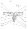
- the embodiment of a sealing plug according to the invention shown in FIG. 2 50 or an accumulator according to the invention has one on one Attached top 56 and penetrating the slosh basket 13 in the direction of the cells
- Charge status and electrolyte level indicators 52 The state of charge and electrolyte level indicator 52 has a viewing rod 53 which extends from the Upper part 56, a lower part 59 and the slosh basket 13, up to a widened lower portion 52a of the charge level and electrolyte level indicator 52 is performed.
- the charge status and electrolyte level indicator 52 dips with its sight stick 53 at a normal level in the electrolyte on.
- the viewing rod 53 After removal of the sealing plug 50 can then on the viewing rod 53 the level of the accumulator with the electrolyte is checked and / or be measured.
- the viewing rod 53 has a rough surface that one Occasionally run in the direction of the lid 1 above a normal level of Ascended electrolyte serves.
Landscapes
- Chemical & Material Sciences (AREA)
- Chemical Kinetics & Catalysis (AREA)
- Electrochemistry (AREA)
- General Chemical & Material Sciences (AREA)
- Engineering & Computer Science (AREA)
- Manufacturing & Machinery (AREA)
- Filling, Topping-Up Batteries (AREA)
- Sealing Battery Cases Or Jackets (AREA)
- Gas Exhaust Devices For Batteries (AREA)
Abstract
Description
- Figur 1a
- einen Teilschnitt durch einen erfindungsgemäßen Akkumulator,
- Figur 1b
- eine Unteransicht auf einen erfindungsgemäßen Verschlussstopfen und
- Figur 2
- eine weitere Ausführungsform des erfindungsgemäßen Verschlussstopfens in einem, in einen Akkumulator eingesetzten Zustand.
Claims (10)
- Akkumulator mit einem, mehrere mit einem Elektrolyten befüllbare Zellen aufweisenden, mit einem Deckel und mit einem Entgasungssystem versehenen Gehäuse, wobei das Entgasungssystem und der Deckel so angeordnet sind, dass sich jeweils daran angebrachte Öffnungen über den Zellen befinden, und wobei jeweils ein Verschlussstopfen in die Öffnungen so einbringbar ist, dass der Verschlussstopfen mit einem Oberteil die Öffnungen nach außen abdeckt und sich in Richtung der Zellen mit einem Unterteil erstreckt, das einen einen Hohlraum umgebenden Schwappkorb aufweist, der über seinen Umfang verteilte Schlitze aufweist, dadurch gekennzeichnet, dass die Schlitze (14) bis zu einem freien Ende (13a) des Schwappkorbes (13) durchgehen.
- Akkumulator nach Anspruch 1, dadurch gekennzeichnet, dass der Verschlussstopfen (5, 50) einstückig ausgebildet ist.
- Akkumulator nach Anspruch 1 oder 2, dadurch gekennzeichnet, dass das Entgasungssystem (2) bei eingebrachtem Verschlussstopfen (5, 50) über eine im Verschlussstopfen (5, 50) vorgesehene Öffnung (10) mit dem Schwappkorb (13) derart verbunden ist, dass die Schlitze (14) Rückläufe für Elektrolyten aus dem Entgasungssystem (2) bilden.
- Akkumulator nach einem der Ansprüche 1 bis 3, dadurch gekennzeichnet, dass der Verschlussstopfen (50) einen an seinem Oberteil (56) befestigten Ladezustands- und/oder Säurestandsanzeiger (52, 53) aufweist, der das Unterteil (59) und den von dem Schwappkorb (13) umgebenen Hohlraum (12) in Längsrichtung durchsetzt.
- Akkumulator nach Anspruch 4, dadurch gekennzeichnet, dass der Ladezustands- und/oder Säurestandsanzeiger (52, 53) und/oder der Schwappkorb (13) eine aufgeraute Oberfläche aufweisen.
- Akkumulator nach einem der Ansprüche 1 bis 5, dadurch gekennzeichnet, dass der Verschlussstopfen (5, 50) aus einem elektrisch leitenden Kunststoff gebildet ist.
- Akkumulator nach Anspruch 6, dadurch gekennzeichnet, dass der Schwappkorb (13) bei eingebrachtem Verschlusssstopfen (5, 50) mit dem freien Ende (13a) den in den Zellen befindlichen Elektrolyten berührt.
- Akkumulator nach einem der Ansprüche 1 bis 7, dadurch gekennzeichnet, dass der Verschlussstopfen (5, 50) eine an dem Oberteil (6, 56) angebrachte Dichtung (7) aufweist, die den Deckel (1) bei eingebrachtem Verschlussstopfen (5, 50) nach außen abdichtet.
- Verschlussstopfen zum Abschließen von in einem Akkumulator oberhalb von Zellen angebrachten Öffnungen, mit einem Oberteil und einem in einen Schwappkorb auslaufenden Unterteil, wobei der Schwappkorb entlang seines Umfangs Schlitze aufweist, dadurch gekennzeichnet, dass die Schlitze (14) bis zu einem freien Ende (13a) des Schwappkorbes (13) durchgehen.
- Verschlussstopfen nach Anspruch 9, dadurch gekennzeichnet, dass an dem Oberteil (56) ein Ladezustands- und Elektrolytstandsanzeiger (52, 53) vorgesehen ist, der den Schwappkorb (13) durchsetzt und an dem freien Ende (13a) herausragt.
Applications Claiming Priority (2)
| Application Number | Priority Date | Filing Date | Title |
|---|---|---|---|
| DE10255290 | 2002-11-26 | ||
| DE10255290A DE10255290B4 (de) | 2002-11-26 | 2002-11-26 | Akkumulator und Verschlussstopfen für einen Akkumulator |
Publications (3)
| Publication Number | Publication Date |
|---|---|
| EP1427038A2 true EP1427038A2 (de) | 2004-06-09 |
| EP1427038A3 EP1427038A3 (de) | 2005-07-13 |
| EP1427038B1 EP1427038B1 (de) | 2009-07-08 |
Family
ID=32308743
Family Applications (1)
| Application Number | Title | Priority Date | Filing Date |
|---|---|---|---|
| EP03023487A Expired - Lifetime EP1427038B1 (de) | 2002-11-26 | 2003-10-18 | Akkumulator und Verschlussstopfen für einen Akkumulator |
Country Status (5)
| Country | Link |
|---|---|
| US (2) | US8252439B2 (de) |
| EP (1) | EP1427038B1 (de) |
| AT (1) | ATE436097T1 (de) |
| DE (2) | DE10255290B4 (de) |
| ES (1) | ES2326368T3 (de) |
Families Citing this family (6)
| Publication number | Priority date | Publication date | Assignee | Title |
|---|---|---|---|---|
| DE10255290B4 (de) | 2002-11-26 | 2006-02-16 | Vb Autobatterie Gmbh | Akkumulator und Verschlussstopfen für einen Akkumulator |
| US20060141342A1 (en) * | 2004-12-23 | 2006-06-29 | David Marconi | Heat dissipating vent cap for battery |
| CN114976401B (zh) * | 2017-08-30 | 2024-03-29 | 宁德时代新能源科技股份有限公司 | 二次电池的顶盖组件和二次电池 |
| DE102019100094A1 (de) * | 2019-01-04 | 2020-07-09 | Mann+Hummel Gmbh | Entgasungseinheit und Elektronikgehäuse, insbesondere Batteriegehäuse |
| US11462778B2 (en) * | 2020-02-18 | 2022-10-04 | Consolidated Edison Company Of New York, Inc. | Battery electrolyte level device |
| KR102157190B1 (ko) * | 2020-07-29 | 2020-09-17 | 에이스이엔지 주식회사 | 차량용 배터리 인디케이터 조립장치 |
Family Cites Families (20)
| Publication number | Priority date | Publication date | Assignee | Title |
|---|---|---|---|---|
| US3083256A (en) * | 1961-06-27 | 1963-03-26 | Ford Motor Co | Battery vent plug |
| FR2219529B1 (de) * | 1973-02-27 | 1978-06-02 | Bosch Gmbh Robert | |
| DE2736243A1 (de) * | 1977-06-08 | 1978-12-14 | Crea Sa | Messelektrode zur bestimmung des konzentrationsgrades von anionenbestandteilen in waessrigen loesungen, verfahren zur aktivierung der messelektrode und ihre verwendung |
| DE3330823A1 (de) * | 1982-08-31 | 1984-03-01 | Accumulatorenfabrik Sonnenschein GmbH, 6470 Büdingen | Verschlussstopfen fuer einen akkumulator |
| DE3330821C2 (de) * | 1983-08-26 | 1985-11-14 | Klaus 6368 Bad Vilbel Queisser | Feinminenstift für den Einsatz an einem Zirkel |
| USD310821S (en) | 1988-11-14 | 1990-09-25 | Globe-Union Inc. | Battery container |
| US5284720A (en) * | 1993-05-27 | 1994-02-08 | Globe-Union Inc. | Vent cap with electrolyte drain and explosion attenuation capabilities |
| US5688612A (en) * | 1994-10-18 | 1997-11-18 | Globe-Union Inc. | Battery cover and vent cap interface seal |
| US5674640A (en) * | 1994-10-20 | 1997-10-07 | Globe-Union, Inc. | Housing system for a multi-cell battery |
| US5702841A (en) * | 1995-07-19 | 1997-12-30 | Globe-Union Inc. | Electrolyte venting system with tubular splash guards |
| US5856037A (en) * | 1997-07-07 | 1999-01-05 | Optima Batteries, Inc. | Battery venting system and method |
| US6143438A (en) * | 1998-02-24 | 2000-11-07 | Johnson Controls Technology Co. | Cold flow sealing vent |
| PT996986E (pt) * | 1998-04-24 | 2002-11-29 | Elke Oschmann | Bujao para bateria |
| DE19856691C2 (de) * | 1998-12-09 | 2003-02-06 | Vb Autobatterie Gmbh | Elektrischer Akkumulator |
| NL1012549C2 (nl) | 1999-07-09 | 2001-01-10 | Ocu Technologies B V | Inktsamenstelling voor een smeltbare inkt en een werkwijze voor het bedrukken van een substraat met een dergelijke inktsamenstelling. |
| US6277517B1 (en) * | 1999-07-12 | 2001-08-21 | Johnson Controls Technology Company | Electrolyte baffling plug |
| DE10015712B4 (de) * | 2000-03-29 | 2009-07-09 | Vb Autobatterie Gmbh & Co. Kgaa | Mehrzelliger Akkumulator mit im Deckel integrierter zentraler Entgasungsleitung |
| DE10023747A1 (de) * | 2000-05-15 | 2001-11-22 | Hoppecke Zoellner Sohn Accu | Stopfenanordnung |
| DE10117576A1 (de) * | 2001-04-07 | 2002-10-10 | Vb Autobatterie Gmbh | Elektrischer Akkumulator |
| DE10255290B4 (de) | 2002-11-26 | 2006-02-16 | Vb Autobatterie Gmbh | Akkumulator und Verschlussstopfen für einen Akkumulator |
-
2002
- 2002-11-26 DE DE10255290A patent/DE10255290B4/de not_active Expired - Fee Related
-
2003
- 2003-10-18 AT AT03023487T patent/ATE436097T1/de active
- 2003-10-18 EP EP03023487A patent/EP1427038B1/de not_active Expired - Lifetime
- 2003-10-18 DE DE50311680T patent/DE50311680D1/de not_active Expired - Lifetime
- 2003-10-18 ES ES03023487T patent/ES2326368T3/es not_active Expired - Lifetime
- 2003-11-12 US US10/706,726 patent/US8252439B2/en not_active Expired - Fee Related
-
2012
- 2012-07-30 US US13/561,326 patent/US8603656B2/en not_active Expired - Fee Related
Also Published As
| Publication number | Publication date |
|---|---|
| EP1427038A3 (de) | 2005-07-13 |
| US8603656B2 (en) | 2013-12-10 |
| US20040137316A1 (en) | 2004-07-15 |
| US8252439B2 (en) | 2012-08-28 |
| DE10255290A1 (de) | 2004-06-09 |
| ES2326368T3 (es) | 2009-10-08 |
| US20120288739A1 (en) | 2012-11-15 |
| DE50311680D1 (de) | 2009-08-20 |
| EP1427038B1 (de) | 2009-07-08 |
| DE10255290B4 (de) | 2006-02-16 |
| ATE436097T1 (de) | 2009-07-15 |
Similar Documents
| Publication | Publication Date | Title |
|---|---|---|
| AT404317B (de) | Verschlussvorrichtung, trennvorrichtung sowie aufnahmebehälter für eine aufnahmeeinrichtung | |
| DE60307517T2 (de) | Flüssigkeitsdichtungsanordnung für austauschbare Flüssigkeitsbehälter | |
| DE3729610C2 (de) | ||
| EP1156538A2 (de) | Stopfenanordnung | |
| DE9102838U1 (de) | Akkumulatoren-Batterie | |
| DE102013105511A1 (de) | Verschlussstopfenanordnung, Gehäuse und Akkumulator | |
| DE10255290B4 (de) | Akkumulator und Verschlussstopfen für einen Akkumulator | |
| DE2935371A1 (de) | Blutsenkunsvorrichtung. | |
| DE10297445T5 (de) | Ventileinheit für die Abdichtung und Entlüftung elektrischer Akkumulatoren | |
| DE9209986U1 (de) | Bleiakkumulator | |
| EP3158615B1 (de) | Bauteil mit zumindest einer öffnung | |
| DE6932118U (de) | Fahrzeug-akkumulatoren-batterie mit automatischer wassernachfuelleinrichtung | |
| EP0996986B1 (de) | Batteriestopfen | |
| EP0040311B1 (de) | Verschlussstopfen für Akkumulatorenzellen | |
| DE102013105817A1 (de) | Verschlussstopfenanordnung, Gehäuse eines Akkumulators und Akkumulator | |
| DE102005027086B4 (de) | Hydrometer/Fluidniveau-Sensor | |
| DE19856691C2 (de) | Elektrischer Akkumulator | |
| DE3035737C2 (de) | Gas- und flüssigkeitsdichte Abdichtung der metallischen Polbuchse eines Akkumulators | |
| DE3236809A1 (de) | Kuehlwasserbehaelter aus thermoplastischem material fuer kraftfahrzeuge | |
| DE1511575A1 (de) | Fuellvorrichtung | |
| DE202005019009U1 (de) | Isolierter Batteriepol für eine Blei-Säure-Batterie | |
| DE3545285C1 (en) | Accumulator having a screw terminal | |
| DE3214148A1 (de) | Sonde zur feststellung des mindestmasses des fluessigkeitsstandes in einem behaeltnis | |
| WO2006058773A1 (de) | Isolierter batteriepol für eine blei-säure-batterie | |
| DE102023114539A1 (de) | Redox-Flow Batterie mit einer Messeinrichtung |
Legal Events
| Date | Code | Title | Description |
|---|---|---|---|
| PUAI | Public reference made under article 153(3) epc to a published international application that has entered the european phase |
Free format text: ORIGINAL CODE: 0009012 |
|
| AK | Designated contracting states |
Kind code of ref document: A2 Designated state(s): AT BE BG CH CY CZ DE DK EE ES FI FR GB GR HU IE IT LI LU MC NL PT RO SE SI SK TR |
|
| AX | Request for extension of the european patent |
Extension state: AL LT LV MK |
|
| PUAL | Search report despatched |
Free format text: ORIGINAL CODE: 0009013 |
|
| AK | Designated contracting states |
Kind code of ref document: A3 Designated state(s): AT BE BG CH CY CZ DE DK EE ES FI FR GB GR HU IE IT LI LU MC NL PT RO SE SI SK TR |
|
| AX | Request for extension of the european patent |
Extension state: AL LT LV MK |
|
| 17P | Request for examination filed |
Effective date: 20050809 |
|
| RAP1 | Party data changed (applicant data changed or rights of an application transferred) |
Owner name: VB AUTOBATTERIE GMBH & CO. KGAA |
|
| AKX | Designation fees paid |
Designated state(s): AT BE BG CH CY CZ DE DK EE ES FI FR GB GR HU IE IT LI LU MC NL PT RO SE SI SK TR |
|
| 17Q | First examination report despatched |
Effective date: 20060707 |
|
| 17Q | First examination report despatched |
Effective date: 20060707 |
|
| GRAP | Despatch of communication of intention to grant a patent |
Free format text: ORIGINAL CODE: EPIDOSNIGR1 |
|
| GRAS | Grant fee paid |
Free format text: ORIGINAL CODE: EPIDOSNIGR3 |
|
| GRAA | (expected) grant |
Free format text: ORIGINAL CODE: 0009210 |
|
| AK | Designated contracting states |
Kind code of ref document: B1 Designated state(s): AT BE BG CH CY CZ DE DK EE ES FI FR GB GR HU IE IT LI LU MC NL PT RO SE SI SK TR |
|
| REG | Reference to a national code |
Ref country code: GB Ref legal event code: FG4D Free format text: NOT ENGLISH |
|
| REG | Reference to a national code |
Ref country code: CH Ref legal event code: EP |
|
| REG | Reference to a national code |
Ref country code: IE Ref legal event code: FG4D |
|
| REF | Corresponds to: |
Ref document number: 50311680 Country of ref document: DE Date of ref document: 20090820 Kind code of ref document: P |
|
| REG | Reference to a national code |
Ref country code: ES Ref legal event code: FG2A Ref document number: 2326368 Country of ref document: ES Kind code of ref document: T3 |
|
| PG25 | Lapsed in a contracting state [announced via postgrant information from national office to epo] |
Ref country code: SI Free format text: LAPSE BECAUSE OF FAILURE TO SUBMIT A TRANSLATION OF THE DESCRIPTION OR TO PAY THE FEE WITHIN THE PRESCRIBED TIME-LIMIT Effective date: 20090708 |
|
| NLV1 | Nl: lapsed or annulled due to failure to fulfill the requirements of art. 29p and 29m of the patents act | ||
| PG25 | Lapsed in a contracting state [announced via postgrant information from national office to epo] |
Ref country code: FI Free format text: LAPSE BECAUSE OF FAILURE TO SUBMIT A TRANSLATION OF THE DESCRIPTION OR TO PAY THE FEE WITHIN THE PRESCRIBED TIME-LIMIT Effective date: 20090708 |
|
| REG | Reference to a national code |
Ref country code: IE Ref legal event code: FD4D |
|
| PG25 | Lapsed in a contracting state [announced via postgrant information from national office to epo] |
Ref country code: NL Free format text: LAPSE BECAUSE OF FAILURE TO SUBMIT A TRANSLATION OF THE DESCRIPTION OR TO PAY THE FEE WITHIN THE PRESCRIBED TIME-LIMIT Effective date: 20090708 |
|
| PG25 | Lapsed in a contracting state [announced via postgrant information from national office to epo] |
Ref country code: BG Free format text: LAPSE BECAUSE OF FAILURE TO SUBMIT A TRANSLATION OF THE DESCRIPTION OR TO PAY THE FEE WITHIN THE PRESCRIBED TIME-LIMIT Effective date: 20091008 Ref country code: PT Free format text: LAPSE BECAUSE OF FAILURE TO SUBMIT A TRANSLATION OF THE DESCRIPTION OR TO PAY THE FEE WITHIN THE PRESCRIBED TIME-LIMIT Effective date: 20091109 |
|
| BERE | Be: lapsed |
Owner name: VB AUTOBATTERIE G.M.B.H. & CO. KGAA Effective date: 20091031 |
|
| PG25 | Lapsed in a contracting state [announced via postgrant information from national office to epo] |
Ref country code: DK Free format text: LAPSE BECAUSE OF FAILURE TO SUBMIT A TRANSLATION OF THE DESCRIPTION OR TO PAY THE FEE WITHIN THE PRESCRIBED TIME-LIMIT Effective date: 20090708 Ref country code: EE Free format text: LAPSE BECAUSE OF FAILURE TO SUBMIT A TRANSLATION OF THE DESCRIPTION OR TO PAY THE FEE WITHIN THE PRESCRIBED TIME-LIMIT Effective date: 20090708 Ref country code: CZ Free format text: LAPSE BECAUSE OF FAILURE TO SUBMIT A TRANSLATION OF THE DESCRIPTION OR TO PAY THE FEE WITHIN THE PRESCRIBED TIME-LIMIT Effective date: 20090708 Ref country code: IE Free format text: LAPSE BECAUSE OF FAILURE TO SUBMIT A TRANSLATION OF THE DESCRIPTION OR TO PAY THE FEE WITHIN THE PRESCRIBED TIME-LIMIT Effective date: 20090708 Ref country code: RO Free format text: LAPSE BECAUSE OF FAILURE TO SUBMIT A TRANSLATION OF THE DESCRIPTION OR TO PAY THE FEE WITHIN THE PRESCRIBED TIME-LIMIT Effective date: 20090708 |
|
| PLBE | No opposition filed within time limit |
Free format text: ORIGINAL CODE: 0009261 |
|
| STAA | Information on the status of an ep patent application or granted ep patent |
Free format text: STATUS: NO OPPOSITION FILED WITHIN TIME LIMIT |
|
| PG25 | Lapsed in a contracting state [announced via postgrant information from national office to epo] |
Ref country code: SK Free format text: LAPSE BECAUSE OF FAILURE TO SUBMIT A TRANSLATION OF THE DESCRIPTION OR TO PAY THE FEE WITHIN THE PRESCRIBED TIME-LIMIT Effective date: 20090708 Ref country code: MC Free format text: LAPSE BECAUSE OF NON-PAYMENT OF DUE FEES Effective date: 20091031 |
|
| REG | Reference to a national code |
Ref country code: CH Ref legal event code: PL |
|
| 26N | No opposition filed |
Effective date: 20100409 |
|
| PG25 | Lapsed in a contracting state [announced via postgrant information from national office to epo] |
Ref country code: GR Free format text: LAPSE BECAUSE OF FAILURE TO SUBMIT A TRANSLATION OF THE DESCRIPTION OR TO PAY THE FEE WITHIN THE PRESCRIBED TIME-LIMIT Effective date: 20091009 Ref country code: LI Free format text: LAPSE BECAUSE OF NON-PAYMENT OF DUE FEES Effective date: 20091031 Ref country code: BE Free format text: LAPSE BECAUSE OF NON-PAYMENT OF DUE FEES Effective date: 20091031 Ref country code: CH Free format text: LAPSE BECAUSE OF NON-PAYMENT OF DUE FEES Effective date: 20091031 |
|
| PG25 | Lapsed in a contracting state [announced via postgrant information from national office to epo] |
Ref country code: GB Free format text: LAPSE BECAUSE OF NON-PAYMENT OF DUE FEES Effective date: 20091018 |
|
| PG25 | Lapsed in a contracting state [announced via postgrant information from national office to epo] |
Ref country code: LU Free format text: LAPSE BECAUSE OF NON-PAYMENT OF DUE FEES Effective date: 20091018 |
|
| PG25 | Lapsed in a contracting state [announced via postgrant information from national office to epo] |
Ref country code: HU Free format text: LAPSE BECAUSE OF FAILURE TO SUBMIT A TRANSLATION OF THE DESCRIPTION OR TO PAY THE FEE WITHIN THE PRESCRIBED TIME-LIMIT Effective date: 20100109 |
|
| PG25 | Lapsed in a contracting state [announced via postgrant information from national office to epo] |
Ref country code: TR Free format text: LAPSE BECAUSE OF FAILURE TO SUBMIT A TRANSLATION OF THE DESCRIPTION OR TO PAY THE FEE WITHIN THE PRESCRIBED TIME-LIMIT Effective date: 20090708 |
|
| PG25 | Lapsed in a contracting state [announced via postgrant information from national office to epo] |
Ref country code: CY Free format text: LAPSE BECAUSE OF FAILURE TO SUBMIT A TRANSLATION OF THE DESCRIPTION OR TO PAY THE FEE WITHIN THE PRESCRIBED TIME-LIMIT Effective date: 20090708 |
|
| PG25 | Lapsed in a contracting state [announced via postgrant information from national office to epo] |
Ref country code: SE Free format text: LAPSE BECAUSE OF FAILURE TO SUBMIT A TRANSLATION OF THE DESCRIPTION OR TO PAY THE FEE WITHIN THE PRESCRIBED TIME-LIMIT Effective date: 20090708 |
|
| REG | Reference to a national code |
Ref country code: DE Ref legal event code: R082 Ref document number: 50311680 Country of ref document: DE Representative=s name: MEISSNER, BOLTE & PARTNER GBR, DE Ref country code: DE Ref legal event code: R082 Ref document number: 50311680 Country of ref document: DE Representative=s name: MEISSNER BOLTE PATENTANWAELTE RECHTSANWAELTE P, DE |
|
| REG | Reference to a national code |
Ref country code: FR Ref legal event code: PLFP Year of fee payment: 13 |
|
| REG | Reference to a national code |
Ref country code: FR Ref legal event code: PLFP Year of fee payment: 14 |
|
| REG | Reference to a national code |
Ref country code: FR Ref legal event code: PLFP Year of fee payment: 15 |
|
| REG | Reference to a national code |
Ref country code: FR Ref legal event code: PLFP Year of fee payment: 16 |
|
| REG | Reference to a national code |
Ref country code: DE Ref legal event code: R082 Ref document number: 50311680 Country of ref document: DE Representative=s name: MEISSNER BOLTE PATENTANWAELTE RECHTSANWAELTE P, DE |
|
| REG | Reference to a national code |
Ref country code: ES Ref legal event code: PC2A Owner name: CLARIOS GERMANY GMBH & CO. KGAA Effective date: 20201027 |
|
| REG | Reference to a national code |
Ref country code: DE Ref legal event code: R079 Ref document number: 50311680 Country of ref document: DE Free format text: PREVIOUS MAIN CLASS: H01M0002120000 Ipc: H01M0050300000 |
|
| REG | Reference to a national code |
Ref country code: DE Ref legal event code: R082 Ref document number: 50311680 Country of ref document: DE Representative=s name: MEISSNER BOLTE PATENTANWAELTE RECHTSANWAELTE P, DE Ref country code: DE Ref legal event code: R081 Ref document number: 50311680 Country of ref document: DE Owner name: CLARIOS GERMANY GMBH & CO. KGAA, DE Free format text: FORMER OWNER: VB AUTOBATTERIE GMBH & CO. KGAA, 30419 HANNOVER, DE |
|
| REG | Reference to a national code |
Ref country code: AT Ref legal event code: HC Ref document number: 436097 Country of ref document: AT Kind code of ref document: T Owner name: CLARIOS GERMANY GMBH & CO. KGAA, DE Effective date: 20210222 |
|
| PGFP | Annual fee paid to national office [announced via postgrant information from national office to epo] |
Ref country code: FR Payment date: 20221025 Year of fee payment: 20 |
|
| PGFP | Annual fee paid to national office [announced via postgrant information from national office to epo] |
Ref country code: IT Payment date: 20221020 Year of fee payment: 20 Ref country code: ES Payment date: 20221102 Year of fee payment: 20 Ref country code: DE Payment date: 20221027 Year of fee payment: 20 Ref country code: AT Payment date: 20221004 Year of fee payment: 20 |
|
| REG | Reference to a national code |
Ref country code: DE Ref legal event code: R071 Ref document number: 50311680 Country of ref document: DE |
|
| REG | Reference to a national code |
Ref country code: ES Ref legal event code: FD2A Effective date: 20231026 |
|
| REG | Reference to a national code |
Ref country code: AT Ref legal event code: MK07 Ref document number: 436097 Country of ref document: AT Kind code of ref document: T Effective date: 20231018 |
|
| PG25 | Lapsed in a contracting state [announced via postgrant information from national office to epo] |
Ref country code: ES Free format text: LAPSE BECAUSE OF EXPIRATION OF PROTECTION Effective date: 20231019 |
|
| PG25 | Lapsed in a contracting state [announced via postgrant information from national office to epo] |
Ref country code: ES Free format text: LAPSE BECAUSE OF EXPIRATION OF PROTECTION Effective date: 20231019 |