EP1426605A2 - A regulation method and device for exhaust gas recirculation - Google Patents
A regulation method and device for exhaust gas recirculation Download PDFInfo
- Publication number
- EP1426605A2 EP1426605A2 EP20040004111 EP04004111A EP1426605A2 EP 1426605 A2 EP1426605 A2 EP 1426605A2 EP 20040004111 EP20040004111 EP 20040004111 EP 04004111 A EP04004111 A EP 04004111A EP 1426605 A2 EP1426605 A2 EP 1426605A2
- Authority
- EP
- European Patent Office
- Prior art keywords
- exhaust gases
- valve
- damper
- dampers
- diesel engine
- Prior art date
- Legal status (The legal status is an assumption and is not a legal conclusion. Google has not performed a legal analysis and makes no representation as to the accuracy of the status listed.)
- Withdrawn
Links
- 238000000034 method Methods 0.000 title claims abstract description 13
- 239000007789 gas Substances 0.000 claims abstract description 31
- 230000001105 regulatory effect Effects 0.000 claims abstract description 13
- 239000000523 sample Substances 0.000 claims abstract description 7
- 239000000446 fuel Substances 0.000 claims abstract description 6
- 230000003993 interaction Effects 0.000 claims 1
- 230000003134 recirculating effect Effects 0.000 claims 1
- MWUXSHHQAYIFBG-UHFFFAOYSA-N Nitric oxide Chemical compound O=[N] MWUXSHHQAYIFBG-UHFFFAOYSA-N 0.000 description 12
- 239000003054 catalyst Substances 0.000 description 3
- 238000002485 combustion reaction Methods 0.000 description 3
- 239000012530 fluid Substances 0.000 description 3
- 239000002245 particle Substances 0.000 description 3
- QVGXLLKOCUKJST-UHFFFAOYSA-N atomic oxygen Chemical compound [O] QVGXLLKOCUKJST-UHFFFAOYSA-N 0.000 description 1
- 230000015572 biosynthetic process Effects 0.000 description 1
- 230000001419 dependent effect Effects 0.000 description 1
- 238000011161 development Methods 0.000 description 1
- 230000018109 developmental process Effects 0.000 description 1
- 231100001261 hazardous Toxicity 0.000 description 1
- 239000000383 hazardous chemical Substances 0.000 description 1
- 239000001301 oxygen Substances 0.000 description 1
- 229910052760 oxygen Inorganic materials 0.000 description 1
- 230000001603 reducing effect Effects 0.000 description 1
Images

Classifications
-
- F—MECHANICAL ENGINEERING; LIGHTING; HEATING; WEAPONS; BLASTING
- F16—ENGINEERING ELEMENTS AND UNITS; GENERAL MEASURES FOR PRODUCING AND MAINTAINING EFFECTIVE FUNCTIONING OF MACHINES OR INSTALLATIONS; THERMAL INSULATION IN GENERAL
- F16K—VALVES; TAPS; COCKS; ACTUATING-FLOATS; DEVICES FOR VENTING OR AERATING
- F16K11/00—Multiple-way valves, e.g. mixing valves; Pipe fittings incorporating such valves
- F16K11/10—Multiple-way valves, e.g. mixing valves; Pipe fittings incorporating such valves with two or more closure members not moving as a unit
- F16K11/14—Multiple-way valves, e.g. mixing valves; Pipe fittings incorporating such valves with two or more closure members not moving as a unit operated by one actuating member, e.g. a handle
- F16K11/16—Multiple-way valves, e.g. mixing valves; Pipe fittings incorporating such valves with two or more closure members not moving as a unit operated by one actuating member, e.g. a handle which only slides, or only turns, or only swings in one plane
- F16K11/163—Multiple-way valves, e.g. mixing valves; Pipe fittings incorporating such valves with two or more closure members not moving as a unit operated by one actuating member, e.g. a handle which only slides, or only turns, or only swings in one plane only turns
- F16K11/165—Multiple-way valves, e.g. mixing valves; Pipe fittings incorporating such valves with two or more closure members not moving as a unit operated by one actuating member, e.g. a handle which only slides, or only turns, or only swings in one plane only turns with the rotating spindles parallel to the closure members
-
- F—MECHANICAL ENGINEERING; LIGHTING; HEATING; WEAPONS; BLASTING
- F02—COMBUSTION ENGINES; HOT-GAS OR COMBUSTION-PRODUCT ENGINE PLANTS
- F02M—SUPPLYING COMBUSTION ENGINES IN GENERAL WITH COMBUSTIBLE MIXTURES OR CONSTITUENTS THEREOF
- F02M26/00—Engine-pertinent apparatus for adding exhaust gases to combustion-air, main fuel or fuel-air mixture, e.g. by exhaust gas recirculation [EGR] systems
- F02M26/02—EGR systems specially adapted for supercharged engines
- F02M26/04—EGR systems specially adapted for supercharged engines with a single turbocharger
- F02M26/06—Low pressure loops, i.e. wherein recirculated exhaust gas is taken out from the exhaust downstream of the turbocharger turbine and reintroduced into the intake system upstream of the compressor
-
- F—MECHANICAL ENGINEERING; LIGHTING; HEATING; WEAPONS; BLASTING
- F02—COMBUSTION ENGINES; HOT-GAS OR COMBUSTION-PRODUCT ENGINE PLANTS
- F02M—SUPPLYING COMBUSTION ENGINES IN GENERAL WITH COMBUSTIBLE MIXTURES OR CONSTITUENTS THEREOF
- F02M26/00—Engine-pertinent apparatus for adding exhaust gases to combustion-air, main fuel or fuel-air mixture, e.g. by exhaust gas recirculation [EGR] systems
- F02M26/13—Arrangement or layout of EGR passages, e.g. in relation to specific engine parts or for incorporation of accessories
- F02M26/17—Arrangement or layout of EGR passages, e.g. in relation to specific engine parts or for incorporation of accessories in relation to the intake system
- F02M26/21—Arrangement or layout of EGR passages, e.g. in relation to specific engine parts or for incorporation of accessories in relation to the intake system with EGR valves located at or near the connection to the intake system
-
- F—MECHANICAL ENGINEERING; LIGHTING; HEATING; WEAPONS; BLASTING
- F02—COMBUSTION ENGINES; HOT-GAS OR COMBUSTION-PRODUCT ENGINE PLANTS
- F02M—SUPPLYING COMBUSTION ENGINES IN GENERAL WITH COMBUSTIBLE MIXTURES OR CONSTITUENTS THEREOF
- F02M26/00—Engine-pertinent apparatus for adding exhaust gases to combustion-air, main fuel or fuel-air mixture, e.g. by exhaust gas recirculation [EGR] systems
- F02M26/52—Systems for actuating EGR valves
- F02M26/53—Systems for actuating EGR valves using electric actuators, e.g. solenoids
- F02M26/54—Rotary actuators, e.g. step motors
-
- F—MECHANICAL ENGINEERING; LIGHTING; HEATING; WEAPONS; BLASTING
- F02—COMBUSTION ENGINES; HOT-GAS OR COMBUSTION-PRODUCT ENGINE PLANTS
- F02M—SUPPLYING COMBUSTION ENGINES IN GENERAL WITH COMBUSTIBLE MIXTURES OR CONSTITUENTS THEREOF
- F02M26/00—Engine-pertinent apparatus for adding exhaust gases to combustion-air, main fuel or fuel-air mixture, e.g. by exhaust gas recirculation [EGR] systems
- F02M26/52—Systems for actuating EGR valves
- F02M26/64—Systems for actuating EGR valves the EGR valve being operated together with an intake air throttle
-
- F—MECHANICAL ENGINEERING; LIGHTING; HEATING; WEAPONS; BLASTING
- F02—COMBUSTION ENGINES; HOT-GAS OR COMBUSTION-PRODUCT ENGINE PLANTS
- F02M—SUPPLYING COMBUSTION ENGINES IN GENERAL WITH COMBUSTIBLE MIXTURES OR CONSTITUENTS THEREOF
- F02M26/00—Engine-pertinent apparatus for adding exhaust gases to combustion-air, main fuel or fuel-air mixture, e.g. by exhaust gas recirculation [EGR] systems
- F02M26/65—Constructional details of EGR valves
- F02M26/70—Flap valves; Rotary valves; Sliding valves; Resilient valves
-
- F—MECHANICAL ENGINEERING; LIGHTING; HEATING; WEAPONS; BLASTING
- F02—COMBUSTION ENGINES; HOT-GAS OR COMBUSTION-PRODUCT ENGINE PLANTS
- F02B—INTERNAL-COMBUSTION PISTON ENGINES; COMBUSTION ENGINES IN GENERAL
- F02B29/00—Engines characterised by provision for charging or scavenging not provided for in groups F02B25/00, F02B27/00 or F02B33/00 - F02B39/00; Details thereof
- F02B29/04—Cooling of air intake supply
- F02B29/0406—Layout of the intake air cooling or coolant circuit
-
- F—MECHANICAL ENGINEERING; LIGHTING; HEATING; WEAPONS; BLASTING
- F02—COMBUSTION ENGINES; HOT-GAS OR COMBUSTION-PRODUCT ENGINE PLANTS
- F02D—CONTROLLING COMBUSTION ENGINES
- F02D9/00—Controlling engines by throttling air or fuel-and-air induction conduits or exhaust conduits
- F02D9/02—Controlling engines by throttling air or fuel-and-air induction conduits or exhaust conduits concerning induction conduits
- F02D2009/0201—Arrangements; Control features; Details thereof
- F02D2009/0276—Throttle and EGR-valve operated together
-
- F—MECHANICAL ENGINEERING; LIGHTING; HEATING; WEAPONS; BLASTING
- F02—COMBUSTION ENGINES; HOT-GAS OR COMBUSTION-PRODUCT ENGINE PLANTS
- F02M—SUPPLYING COMBUSTION ENGINES IN GENERAL WITH COMBUSTIBLE MIXTURES OR CONSTITUENTS THEREOF
- F02M26/00—Engine-pertinent apparatus for adding exhaust gases to combustion-air, main fuel or fuel-air mixture, e.g. by exhaust gas recirculation [EGR] systems
- F02M26/13—Arrangement or layout of EGR passages, e.g. in relation to specific engine parts or for incorporation of accessories
- F02M26/14—Arrangement or layout of EGR passages, e.g. in relation to specific engine parts or for incorporation of accessories in relation to the exhaust system
- F02M26/15—Arrangement or layout of EGR passages, e.g. in relation to specific engine parts or for incorporation of accessories in relation to the exhaust system in relation to engine exhaust purifying apparatus
-
- F—MECHANICAL ENGINEERING; LIGHTING; HEATING; WEAPONS; BLASTING
- F02—COMBUSTION ENGINES; HOT-GAS OR COMBUSTION-PRODUCT ENGINE PLANTS
- F02M—SUPPLYING COMBUSTION ENGINES IN GENERAL WITH COMBUSTIBLE MIXTURES OR CONSTITUENTS THEREOF
- F02M26/00—Engine-pertinent apparatus for adding exhaust gases to combustion-air, main fuel or fuel-air mixture, e.g. by exhaust gas recirculation [EGR] systems
- F02M26/13—Arrangement or layout of EGR passages, e.g. in relation to specific engine parts or for incorporation of accessories
- F02M26/22—Arrangement or layout of EGR passages, e.g. in relation to specific engine parts or for incorporation of accessories with coolers in the recirculation passage
- F02M26/23—Layout, e.g. schematics
-
- F—MECHANICAL ENGINEERING; LIGHTING; HEATING; WEAPONS; BLASTING
- F02—COMBUSTION ENGINES; HOT-GAS OR COMBUSTION-PRODUCT ENGINE PLANTS
- F02M—SUPPLYING COMBUSTION ENGINES IN GENERAL WITH COMBUSTIBLE MIXTURES OR CONSTITUENTS THEREOF
- F02M26/00—Engine-pertinent apparatus for adding exhaust gases to combustion-air, main fuel or fuel-air mixture, e.g. by exhaust gas recirculation [EGR] systems
- F02M26/45—Sensors specially adapted for EGR systems
- F02M26/48—EGR valve position sensors
-
- Y—GENERAL TAGGING OF NEW TECHNOLOGICAL DEVELOPMENTS; GENERAL TAGGING OF CROSS-SECTIONAL TECHNOLOGIES SPANNING OVER SEVERAL SECTIONS OF THE IPC; TECHNICAL SUBJECTS COVERED BY FORMER USPC CROSS-REFERENCE ART COLLECTIONS [XRACs] AND DIGESTS
- Y10—TECHNICAL SUBJECTS COVERED BY FORMER USPC
- Y10T—TECHNICAL SUBJECTS COVERED BY FORMER US CLASSIFICATION
- Y10T137/00—Fluid handling
- Y10T137/8593—Systems
- Y10T137/87153—Plural noncommunicating flow paths
- Y10T137/87161—With common valve operator
Definitions
- the present invention is related to a regulation method and device for a diesel engine.
- EGR-systems In order to reduce the contents of hazardous exhaust gases, particularly nitrogen oxide (NOx), so called EGR-systems are used since many years in many types of combustion engines. Such systems admit a part of the exhaust gases to be recirculated to the intake system of the engine, where it is mixed with the intake air and is conveyed further to the combustion chamber of the engine. The recirculated exhaust gases replace a part of the intake air and have a reducing effect on the formation of NOx. A so called EGR-valve is then placed in connection with the exhaust system of the engine, the purpose of said valve being to regulate the amount of recirculated exhaust gases.
- NOx nitrogen oxide
- valve device comprises separate dampers arranged in the EGR-recirculation channel and an air intake channel. Separate drive motors are provided for these dampers, a fact which makes the valve device complicated and this also applies for a control device therefor.
- the object of the invention is to provide a regulation method and device providing for improved regulation possibilities with regard to a diesel engine provided with an EGR-system.
- this invention is based on use of probes and sensors connected to a control device for the valve device so as to enable regulation not only of the relation air/recirculated exhaust gases but also regulation of the air/fuel relation of the engine.
- This invention provides for an improved overall regulation of the engine and a smaller amount of pollution.
- Fig 1 is a diagrammatical view showing the parts, which are essential to the invention, of a combustion engine indicated with the reference character 1.
- the engine is in the selected embodiment example a turbo charged diesel engine but as already mentioned the engine may be a diesel engine without super charging or a diesel engine with a different type of super charging than a turbo charger.
- Air is taken to the engine 1 through an air intake, an air filter 2, and is directed via an inlet air channel 3 to a turbo charger 4, where the air is super charged and then conveyed further through an intercooler 5, where the super charged air is cooled down before it is conveyed into the engine 1.
- the exhaust gases from the engine 1 are first directed through the second side of the turbo charger 4, namely that side which is the driving one, and then through an exhaust pipe 6, a catalyst 7 and a particle trap 8 to finally be emitted to the open air via an end pipe 9.
- a recirculation conduit 10 to recirculate from the exhaust gases a part thereof to the engine.
- the recirculation conduit 10 passes suitably through a cooler 11 to cool down the recirculated exhaust gases and it connects to the inlet air channel 3 via a valve device 12 controllable by means of an EGR control device 13.
- the valve device 12 may, with the assistance of the EGR control device 13, regulate the relation between the supplied amount of fresh air from the inlet air channel 3 and the supplied amount of recirculated exhaust gases from the recirculation conduit 10.
- the EGR control device 13 regulating the valve device 12 is supplied with information about the actual operational state of the engine from a.o. a Lambda probe 14, a sensor 15 for the number of revolutions of the engine and a sensor 16 for engine load and this control device is programmed to control the valve device 12 and, accordingly, the mixing relation fresh air/exhaust gases for the purpose of minimising the contents of hazardous substances leaving the end pipe 9 and being emitted into the open air.
- the programming of the EGR control device 13 occurs in a previously known manner with regard to the relations between the different factors given hereinabove.
- a Lambda probe provides an output signal varying with the oxygen contents of the exhaust gases.
- the engine load sensor 16 may for instance be a throttle position sensor and/or a sensor sensing the amount of fuel injected to the engine. Also other sensors than those mentioned may be added to achieve a refined regulation.
- the valve device 12 may comprise separate valves in the inlet air channel 3 and in the recirculation conduit 10, said valves then being separately controllable by the EGR control device 13.
- the valve device 12 may also comprise a unit, in which flows from the inlet air channel 3 and the recirculation conduit 10 may be selectively brought together, by means of valves contained in the valve device, to a common output flow, which is conveyed further to the turbo charger for super charging and introduction into the engine via the intercooler 5.
- a particularly suitable valve device 12 in one unit will be described more closely hereunder.
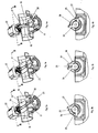
- the valve illustrated in Figs 2-4 is a type of mixing valve providing for mixing of two in-flowing fluids in such a manner that the in-flowing fluid in one of the two inlet channels may be regulated from 0 to maximum, and thereafter the in-flowing fluid in the second inlet channel from a maximum to 0.
- the inlet air channel 3 is connected to the second inlet channel 18 of the valve, whereas the recirculation conduit 10 is connected to the first inlet channel 17 of the valve. Furthermore, there is in the valve an outlet channel 19, which in the present embodiment conveys the gases mixed in the valve to the turbo charger 4.
- dampers 20 and 21 which are pivotable between an open and a closed position by means of an adjustment motor 22, for instance a step motor, to open or close the inlet channels.
- the two dampers 20, 21 are placed on concentric axles 23, 24, which are rotatable by means of the adjustment motor 22 and an actuation pin 25 driven by the motor, said actuation pin being capable of pivoting actuation arms 26, 27 connected to the axles 23 and 24 respectively.
- the actuation arms 26, 27 are spring loaded by one or more springs 28, 29 to a normal position, illustrated in Fig 3, where both dampers 20, 21 are held in a position such that the inlet channels 17, 18 are open.
- the adjustment motor 22 has, by means of its actuation pin 25 and by means of the actuation arm 26, rotated the damper 20 to a closed position, and thus, the first inlet channel 17 connected to the recirculation conduit 10 is closed and no exhaust gases may be recirculated to the turbo charger and the engine.
- the second actuation arm 27 is maintained in its normal position by the spring 29, which means that the damper 21 in the second inlet channel 18 connected to the inlet air channel 3 is maintained in its normally opened position and allows free flow of inlet air through the valve via the outlet channel 19 to the turbo charger.
- the adjustment motor 22 is controlled by the EGR control device 13 to regulate the relation between fresh air via the inlet air channel 3 and recirculated exhaust gases via the recirculation conduit 10.
- the adjustment motor 22 may rotate, by means of its actuation pin 25 and by means of the actuation arm 26, the damper 20 from the entirely closed position shown in Fig 2a, b to the position which is shown in Fig 3a, b where also the damper 20 is in such a position that also the first inlet channel 17 is open.
- the adjustment motor may also adjust the damper 20 into any position between these two end positions.
- Fig 3a, b which is the normal position for the adjustment motor 20, is such that the actuation pin 25 of the adjustment motor does not actuate any of the actuation arms 26, 27 but they are maintained by the springs 28, 29 in a normal position, where, accordingly, the dampers 20, 21 open both inlet channels 17, 18.
- Fig 4a, b illustrates a position contrary to the one in Fig 2a, b.
- the adjustment motor 22 has by means of its actuation pin 25 and by means of the actuation arm 27 rotated the damper 21 to a closed position, which means that the connection of the inlet air channel 3 with the outlet channel 19 is entirely interrupted whereas on the contrary the first inlet channel 17 connected to the recirculation conduit 10 is entirely open and allows the recirculated exhaust gases to freely flow further through the outlet channel 19 and then to the turbo charger 4 and further on to the engine.
- the damper 21 may be adjusted into any intermediate position between the end positions illustrated in Figs 3 and 4 to allow a desired amount, controlled by the EGR control device 13, of fresh air to be mixed with the recirculated exhaust gases.
- valve it becomes possible to control, in a simple manner, a three-way valve having two inlets and having a normal position, where both inlets are open so that one or the other of the inlets may be controlled steplessly whereas the remaining inlet is maintained open.
- a control device which is supplied with information from a lambda probe 14, a motor speed sensor 15 and an engine load sensor 16.
- the control device is connected to a valve device, corresponding to the valve device 12 described here-inabove, for regulation of the in-flowing amounts of air and/or recirculated exhaust gases to the engine.
- This valve device is arranged between the air filter and the inlet channel of the engine and may, as also has been described for the valve device 12, comprise separate valves in the inlet air channel and recirculation conduit, or a three-way valve of the kind also described hereinabove.
- the valve device is controllable in a corresponding manner as also described hereinabove, and the control device may therefore control, based on the input signals received, the air/fuel relation of the engine by regulating the amount of in-flowing air and simultaneously regulating the relation between the supplied fresh air and recirculated exhaust gases.
- This invention is applicable with or without supercharging.
Landscapes
- Engineering & Computer Science (AREA)
- General Engineering & Computer Science (AREA)
- Mechanical Engineering (AREA)
- Chemical & Material Sciences (AREA)
- Combustion & Propulsion (AREA)
- Exhaust-Gas Circulating Devices (AREA)
- Output Control And Ontrol Of Special Type Engine (AREA)
- Control Of Throttle Valves Provided In The Intake System Or In The Exhaust System (AREA)
- Exhaust Gas After Treatment (AREA)
- Electrical Control Of Air Or Fuel Supplied To Internal-Combustion Engine (AREA)
- Combined Controls Of Internal Combustion Engines (AREA)
- Lift Valve (AREA)
- Supercharger (AREA)
Abstract
Description
- The present invention is related to a regulation method and device for a diesel engine.
- In order to reduce the contents of hazardous exhaust gases, particularly nitrogen oxide (NOx), so called EGR-systems are used since many years in many types of combustion engines. Such systems admit a part of the exhaust gases to be recirculated to the intake system of the engine, where it is mixed with the intake air and is conveyed further to the combustion chamber of the engine. The recirculated exhaust gases replace a part of the intake air and have a reducing effect on the formation of NOx. A so called EGR-valve is then placed in connection with the exhaust system of the engine, the purpose of said valve being to regulate the amount of recirculated exhaust gases.
- A method and a device for exhaust gas recirculation are disclosed in DE A1 4 007 516. Although this prior art makes it possible to use an EGR-system in super charged diesel engines, where the pressure in the intake system downstream of the super charger is higher than the pressure in a recirculation conduit from an EGR-valve some important disadvantages are inherent in this prior art. Thus, the valve device comprises separate dampers arranged in the EGR-recirculation channel and an air intake channel. Separate drive motors are provided for these dampers, a fact which makes the valve device complicated and this also applies for a control device therefor.
- The object of the invention is to provide a regulation method and device providing for improved regulation possibilities with regard to a diesel engine provided with an EGR-system.
- The object of the invention is achieved by means of the regulation method and device as defined in the characterising parts of
claims 1 and 5. Thus, this invention is based on use of probes and sensors connected to a control device for the valve device so as to enable regulation not only of the relation air/recirculated exhaust gases but also regulation of the air/fuel relation of the engine. This invention provides for an improved overall regulation of the engine and a smaller amount of pollution. - Preferable developments of the invention are defined in dependent claims.
- The use of an EGR-system as contemplated by the invention on an engine provided with a catalyst and a particle filter according to the prior art results in a substantial reduction of the NOx contents. This reduction may be up to 50% and makes it possible to upgrade existing diesel engines to present emission requirements and to upgrade modern diesel engines to future emission requirements.
- The invention will now be described by means of non-limiting embodiments illustrated in the drawings, where
- Fig 1
- illustrates a diagrammatical view of a device according to the invention;
- Fig 2a
- illustrates a sectioned valve in one end position;
- Fig 2b
- is a section view of the valve in Fig 2a as viewed in the direction of the arrow B-B;
- Fig 3a
- illustrates a sectioned valve in an intermediate position;
- Fig 3b
- illustrates a section view of the valve in Fig 3a as viewed in the direction of the arrow B-B;
- Fig 4a
- illustrates a cut valve in a second end position; and
- Fig 4b
- illustrates a section view of the valve in Fig 4a as viewed in the direction of the arrow B-B.
- Fig 1 is a diagrammatical view showing the parts, which are essential to the invention, of a combustion engine indicated with the reference character 1. The engine is in the selected embodiment example a turbo charged diesel engine but as already mentioned the engine may be a diesel engine without super charging or a diesel engine with a different type of super charging than a turbo charger. Air is taken to the engine 1 through an air intake, an
air filter 2, and is directed via aninlet air channel 3 to aturbo charger 4, where the air is super charged and then conveyed further through anintercooler 5, where the super charged air is cooled down before it is conveyed into the engine 1. The exhaust gases from the engine 1 are first directed through the second side of theturbo charger 4, namely that side which is the driving one, and then through anexhaust pipe 6, acatalyst 7 and aparticle trap 8 to finally be emitted to the open air via anend pipe 9. - From the
end pipe 9, i.e. an extension of the exhaust pipe after the catalyst and particle trap, there is a branch, arecirculation conduit 10, to recirculate from the exhaust gases a part thereof to the engine. The recirculation conduit 10 passes suitably through acooler 11 to cool down the recirculated exhaust gases and it connects to theinlet air channel 3 via avalve device 12 controllable by means of anEGR control device 13. Thevalve device 12 may, with the assistance of theEGR control device 13, regulate the relation between the supplied amount of fresh air from theinlet air channel 3 and the supplied amount of recirculated exhaust gases from therecirculation conduit 10. - The EGR
control device 13 regulating thevalve device 12 is supplied with information about the actual operational state of the engine from a.o. a Lambdaprobe 14, asensor 15 for the number of revolutions of the engine and asensor 16 for engine load and this control device is programmed to control thevalve device 12 and, accordingly, the mixing relation fresh air/exhaust gases for the purpose of minimising the contents of hazardous substances leaving theend pipe 9 and being emitted into the open air. The programming of theEGR control device 13 occurs in a previously known manner with regard to the relations between the different factors given hereinabove. As is well known, a Lambda probe provides an output signal varying with the oxygen contents of the exhaust gases. Theengine load sensor 16 may for instance be a throttle position sensor and/or a sensor sensing the amount of fuel injected to the engine. Also other sensors than those mentioned may be added to achieve a refined regulation. - The
valve device 12 may comprise separate valves in theinlet air channel 3 and in therecirculation conduit 10, said valves then being separately controllable by theEGR control device 13. Alternatively thevalve device 12 may also comprise a unit, in which flows from theinlet air channel 3 and therecirculation conduit 10 may be selectively brought together, by means of valves contained in the valve device, to a common output flow, which is conveyed further to the turbo charger for super charging and introduction into the engine via theintercooler 5. A particularlysuitable valve device 12 in one unit will be described more closely hereunder. - The valve illustrated in Figs 2-4 is a type of mixing valve providing for mixing of two in-flowing fluids in such a manner that the in-flowing fluid in one of the two inlet channels may be regulated from 0 to maximum, and thereafter the in-flowing fluid in the second inlet channel from a maximum to 0.
- In use of the valve illustrated in Figs 2-4 as a
valve device 12 in the method or device according to the invention, theinlet air channel 3 is connected to thesecond inlet channel 18 of the valve, whereas therecirculation conduit 10 is connected to thefirst inlet channel 17 of the valve. Furthermore, there is in the valve anoutlet channel 19, which in the present embodiment conveys the gases mixed in the valve to theturbo charger 4. In bothinlet channels dampers adjustment motor 22, for instance a step motor, to open or close the inlet channels. The twodampers concentric axles adjustment motor 22 and anactuation pin 25 driven by the motor, said actuation pin being capable of pivotingactuation arms axles actuation arms more springs dampers inlet channels - In the position illustrated in Fig 2a, b, which is a starting position, the
adjustment motor 22 has, by means of itsactuation pin 25 and by means of theactuation arm 26, rotated thedamper 20 to a closed position, and thus, thefirst inlet channel 17 connected to therecirculation conduit 10 is closed and no exhaust gases may be recirculated to the turbo charger and the engine. - The
second actuation arm 27 is maintained in its normal position by thespring 29, which means that thedamper 21 in thesecond inlet channel 18 connected to theinlet air channel 3 is maintained in its normally opened position and allows free flow of inlet air through the valve via theoutlet channel 19 to the turbo charger. Theadjustment motor 22 is controlled by theEGR control device 13 to regulate the relation between fresh air via theinlet air channel 3 and recirculated exhaust gases via therecirculation conduit 10. In the position with thedamper 21 open, theadjustment motor 22 may rotate, by means of itsactuation pin 25 and by means of theactuation arm 26, thedamper 20 from the entirely closed position shown in Fig 2a, b to the position which is shown in Fig 3a, b where also thedamper 20 is in such a position that also thefirst inlet channel 17 is open. The adjustment motor may also adjust thedamper 20 into any position between these two end positions. - The position illustrated in Fig 3a, b, which is the normal position for the
adjustment motor 20, is such that theactuation pin 25 of the adjustment motor does not actuate any of theactuation arms springs dampers inlet channels - Fig 4a, b illustrates a position contrary to the one in Fig 2a, b. Thus, the
adjustment motor 22 has by means of itsactuation pin 25 and by means of theactuation arm 27 rotated thedamper 21 to a closed position, which means that the connection of theinlet air channel 3 with theoutlet channel 19 is entirely interrupted whereas on the contrary thefirst inlet channel 17 connected to therecirculation conduit 10 is entirely open and allows the recirculated exhaust gases to freely flow further through theoutlet channel 19 and then to theturbo charger 4 and further on to the engine. However, by means of theadjustment motor 22, thedamper 21 may be adjusted into any intermediate position between the end positions illustrated in Figs 3 and 4 to allow a desired amount, controlled by theEGR control device 13, of fresh air to be mixed with the recirculated exhaust gases. - Thus, with the valve it becomes possible to control, in a simple manner, a three-way valve having two inlets and having a normal position, where both inlets are open so that one or the other of the inlets may be controlled steplessly whereas the remaining inlet is maintained open.
- In a regulation method according to the invention, a control device is used which is supplied with information from a
lambda probe 14, amotor speed sensor 15 and anengine load sensor 16. The control device is connected to a valve device, corresponding to thevalve device 12 described here-inabove, for regulation of the in-flowing amounts of air and/or recirculated exhaust gases to the engine. This valve device is arranged between the air filter and the inlet channel of the engine and may, as also has been described for thevalve device 12, comprise separate valves in the inlet air channel and recirculation conduit, or a three-way valve of the kind also described hereinabove. The valve device is controllable in a corresponding manner as also described hereinabove, and the control device may therefore control, based on the input signals received, the air/fuel relation of the engine by regulating the amount of in-flowing air and simultaneously regulating the relation between the supplied fresh air and recirculated exhaust gases. This invention is applicable with or without supercharging. - With the regulation method and device according to the invention it is possible to further decrease the NOx-contents in the exhaust gases exiting from the end pipe of a diesel engine.
Claims (11)
- A method for regulating a diesel engine, a part of the exhaust gases from the diesel engine being recirculated to the inlet thereof and a supply of fresh air and recirculated exhaust gases to the diesel engine being regulated by means of a valve device (12) controlled by a control device (13) to regulate the relation between the supplied fresh air and recirculated exhaust gases, characterized in that the control device (13) is supplied with information from a Lambda probe (14), an engine speed sensor (15) and an engine load sensor (16) so as to regulate the air/fuel relation of the diesel engine by means of said information and the valve device.
- A regulating method according to claim 1, characterized in that a valve device comprising a first inlet channel (17) for the recirculated exhaust gases, a second inlet channel (18) for the fresh air, a first damper (20) arranged in the first inlet channel (17) and a second damper (21) arranged in the second inlet channel (18) is used as said valve device (12), and that at least one of the dampers (20, 21) always is maintained open and the other damper (20, 21) is closed by means of a motor (22) common to the dampers.
- A regulating method according to claim 2, characterized in that the motor (22) operates one of the dampers (20, 21) at a time and adjusts the same into any position between the open position and the closed position.
- A regulating method according to claim 2 or 3, characterized in that both dampers (20, 21) in a normal position are spring loaded (28, 29) to an open position.
- A regulating device for a diesel engine, comprising means (10) for recirculating a part of exhaust gases from the diesel engine to an inlet thereof and a valve device (12) controlled by a control device (13) for regulating supply of fresh air and recirculated exhaust gases to the diesel engine so as to regulate the relation between supplied fresh air and recirculated exhaust gases, characterized in that a Lambda probe (14), an engine speed sensor (15) and an engine load sensor (16) are connected to the control device (13) to supply information thereto and that the control device (13) is arranged to regulate the air/fuel relation of the diesel engine by means of said information and the valve device (12).
- A device according to claim 5, characterized in that the valve device (12) comprises a first inlet channel (17) for the recirculated exhaust gases, a second inlet channel (18) for the fresh air, a first damper (20) arranged in the first inlet channel (17) and a second damper (21) arranged in the second inlet channel (18), wherein at least one of the dampers (20, 21) always is open and a motor (22) common to the dampers is arranged to close the other damper (20, 21).
- A device according to claim 6, characterized in that the motor (22) is arranged to operate one of the dampers (20, 21) at a time and adjust the same into any position between the open position and the closed position.
- A device according to claim 6 or 7, characterized in that both dampers (20, 21) in a normal position are spring loaded (28, 29) to an open position.
- A device according to any of claims 6-8, characterized in that the valve device (12) comprises a first axle (23) on which the first damper (20) is arranged and a second axle (24) on which the second damper (21) is arranged, the first and second axles (23, 24) being concentric, and that both axles (23, 24) are arranged to be rotatable by the motor (22).
- A valve according to claim 9, characterized in that the first axle (23) is connected to a first actuation arm (26), that the second axle (24) is connected to a second actuation arm (27), and that the valve (12) comprises an actuation pin (25) which is moveable by means of the motor (22) in order to rotate the first axle (23) and the second axle (24) by interaction with the first actuation arm (26) and the second actuation arm (27), respectively, so as to control the position of the dampers (20, 21).
- A valve according to claim 10, characterized in that the valve (12) comprises springs (28, 29) acting on the actuation arms (26, 27) so as to spring load each damper (20, 21) towards an open position.
Applications Claiming Priority (5)
| Application Number | Priority Date | Filing Date | Title |
|---|---|---|---|
| SE9803827A SE521751C2 (en) | 1998-11-09 | 1998-11-09 | Method for recirculating part of exhaust gases from exhaust pipe of diesel engine to its inlet has at least one of dampers always maintained open and that other damper closed using drive motor common to dampers |
| SE9803827 | 1998-11-09 | ||
| SE9804240A SE521713C2 (en) | 1998-11-09 | 1998-12-07 | Procedure and apparatus for an EGR system, and such valve |
| SE9804240 | 1998-12-07 | ||
| EP99958578A EP1129281B1 (en) | 1998-11-09 | 1999-11-09 | A method and device for an egr-system and a valve |
Related Parent Applications (1)
| Application Number | Title | Priority Date | Filing Date |
|---|---|---|---|
| EP99958578A Division EP1129281B1 (en) | 1998-11-09 | 1999-11-09 | A method and device for an egr-system and a valve |
Publications (2)
| Publication Number | Publication Date |
|---|---|
| EP1426605A2 true EP1426605A2 (en) | 2004-06-09 |
| EP1426605A3 EP1426605A3 (en) | 2009-01-07 |
Family
ID=26663430
Family Applications (2)
| Application Number | Title | Priority Date | Filing Date |
|---|---|---|---|
| EP99958578A Expired - Lifetime EP1129281B1 (en) | 1998-11-09 | 1999-11-09 | A method and device for an egr-system and a valve |
| EP20040004111 Withdrawn EP1426605A3 (en) | 1998-11-09 | 1999-11-09 | A regulation method and device for exhaust gas recirculation |
Family Applications Before (1)
| Application Number | Title | Priority Date | Filing Date |
|---|---|---|---|
| EP99958578A Expired - Lifetime EP1129281B1 (en) | 1998-11-09 | 1999-11-09 | A method and device for an egr-system and a valve |
Country Status (18)
| Country | Link |
|---|---|
| US (3) | US6925992B1 (en) |
| EP (2) | EP1129281B1 (en) |
| JP (1) | JP2002529653A (en) |
| KR (1) | KR100749706B1 (en) |
| CN (2) | CN1529047A (en) |
| AT (1) | ATE287496T1 (en) |
| AU (1) | AU754789C (en) |
| BR (1) | BR9915167A (en) |
| CA (1) | CA2347874C (en) |
| DE (1) | DE69923341T2 (en) |
| IL (2) | IL161161A0 (en) |
| MY (1) | MY125895A (en) |
| NZ (1) | NZ511364A (en) |
| PL (1) | PL199883B1 (en) |
| RU (1) | RU2230212C2 (en) |
| SE (1) | SE521713C2 (en) |
| TR (1) | TR200101301T2 (en) |
| WO (1) | WO2000028203A1 (en) |
Cited By (2)
| Publication number | Priority date | Publication date | Assignee | Title |
|---|---|---|---|---|
| WO2006076938A1 (en) * | 2005-01-18 | 2006-07-27 | Bayerische Motoren Werke Aktiengesellschaft | Vehicle comprising an exhaust gas recirculation system |
| CN103574094A (en) * | 2012-07-29 | 2014-02-12 | 浙江三花汽车零部件有限公司 | Flow regulating valve |
Families Citing this family (99)
| Publication number | Priority date | Publication date | Assignee | Title |
|---|---|---|---|---|
| DE19927673A1 (en) * | 1999-06-17 | 2000-12-21 | Bosch Gmbh Robert | Air feed change-over device to switch between film and homogenous operations has shaft with flat sections to form slides, and fitted into a housing bore |
| JP3791318B2 (en) * | 2000-10-02 | 2006-06-28 | トヨタ自動車株式会社 | Exhaust gas purification device for an internal combustion engine with a supercharger |
| DE10117512A1 (en) * | 2001-04-07 | 2002-10-17 | Volkswagen Ag | Internal combustion engine with direct injection |
| DE10210202C1 (en) | 2002-03-07 | 2003-11-13 | Man B & W Diesel Ag | reciprocating internal combustion engine |
| FR2840024B1 (en) * | 2002-05-22 | 2006-06-23 | Peugeot Citroen Automobiles Sa | GAS SUPPLY SYSTEM FOR A DIESEL ENGINE OF A MOTOR VEHICLE |
| FR2840648B1 (en) * | 2002-06-11 | 2006-08-04 | Inst Francais Du Petrole | DEVICE AND METHOD FOR CONTROLLING EXHAUST GAS RECIRCULATION FOR AN INTERNAL COMBUSTION ENGINE, IN PARTICULAR OF THE DIESEL TYPE |
| FR2845732B1 (en) * | 2002-10-14 | 2006-04-28 | Renault Sa | SYSTEM FOR CONTROLLING THE OPERATION OF AN INTERNAL COMBUSTION ENGINE AND METHOD FOR CONTROLLING EXHAUST GAS RECIRCULATION USING SUCH A CONTROL SYSTEM. |
| JPWO2005052347A1 (en) * | 2003-11-28 | 2007-06-21 | 株式会社日立製作所 | Diesel engine EGR control device and motor-driven throttle valve device |
| SE526824C2 (en) | 2004-03-26 | 2005-11-08 | Stt Emtec Ab | Valve |
| SE526804C2 (en) | 2004-03-26 | 2005-11-08 | Stt Emtec Ab | valve device |
| US7922702B2 (en) | 2004-07-02 | 2011-04-12 | Qlt Inc. | Treatment medium delivery device and methods for delivery of such treatment mediums to the eye using such a delivery device |
| DE102004044895A1 (en) | 2004-09-14 | 2006-03-30 | Volkswagen Ag | Exhaust gas recirculation device and method for operating the exhaust gas recirculation device |
| JP4300364B2 (en) * | 2004-09-29 | 2009-07-22 | 日産自動車株式会社 | Supercharging pressure regulator for variable supercharging system |
| DE102004055846B4 (en) * | 2004-11-19 | 2016-12-15 | Bayerische Motoren Werke Aktiengesellschaft | Vehicle with turbo diesel engine and exhaust gas recirculation |
| DE102005009638A1 (en) * | 2005-03-03 | 2006-09-07 | Bayerische Motoren Werke Ag | Vehicle having exhaust gas recirculation system e.g. for diesel engine, has branch-off valve located in exhaust gas tract, having inlet and outlet connected to exhaust gas tail pipe |
| DE102005002266A1 (en) * | 2005-01-18 | 2006-07-20 | Bayerische Motoren Werke Ag | Exhaust gas recirculation system for internal combustion engine has two throttle elements which are assigned to common actuator whereby first throttle element is arranged in direction of flow behind exhaust gas return line |
| DE102005014264A1 (en) * | 2005-03-24 | 2006-09-28 | Emitec Gesellschaft Für Emissionstechnologie Mbh | Exhaust system with an exhaust gas treatment unit and a heat exchanger in an exhaust gas recirculation line |
| DE102005048911A1 (en) * | 2005-10-10 | 2007-04-12 | Behr Gmbh & Co. Kg | Arrangement for returning and cooling exhaust gas of an internal combustion engine |
| US7357125B2 (en) * | 2005-10-26 | 2008-04-15 | Honeywell International Inc. | Exhaust gas recirculation system |
| FR2894315B1 (en) * | 2005-12-02 | 2008-02-15 | Valeo Sys Controle Moteur Sas | VALVE COMPRISING MEANS FOR ACTUATING BETWEEN TWO OUTPUT DUCTS. |
| FR2894623B1 (en) * | 2005-12-08 | 2008-02-01 | Renault Sas | METHOD FOR CONTROLLING AN ENGINE COMPRISING A LOW PRESSURE TYPE EXHAUST GAS RECIRCULATION LOOP |
| WO2007089771A2 (en) * | 2006-01-31 | 2007-08-09 | Borgwarner Inc. | Integrated egr valve and throttle valve |
| CN101405500B (en) * | 2006-03-22 | 2015-07-08 | 博格华纳公司 | Two component low pressure EGR module |
| CN101415933B (en) * | 2006-03-22 | 2012-06-20 | 博格华纳公司 | Integrated charge air and EGR valve |
| US7690397B2 (en) * | 2006-05-15 | 2010-04-06 | Hollis Thomas J | Digital rotary control valve |
| US20070297961A1 (en) * | 2006-06-27 | 2007-12-27 | Caterpillar Inc. | System for removing sulfur oxides from recycled exhaust |
| US7805931B2 (en) * | 2006-10-30 | 2010-10-05 | Perkins Engines Company Limited | Self-sustaining oxy-exothermal filter regeneration system |
| JP4424345B2 (en) | 2006-11-29 | 2010-03-03 | トヨタ自動車株式会社 | Exhaust gas recirculation device for internal combustion engine |
| US7591131B2 (en) * | 2006-11-30 | 2009-09-22 | Caterpillar Inc. | Low pressure EGR system having full range capability |
| DE102007033925A1 (en) | 2007-07-20 | 2009-01-22 | Volkswagen Ag | Exhaust gas recirculation device for exhaust gas of internal combustion engine of motor vehicle, comprises exhaust pipe to supply exhaust gas to particle separator, where valve is arranged in particle separator |
| FR2926114B1 (en) * | 2008-01-03 | 2012-12-14 | Valeo Sys Controle Moteur Sas | EGR LOOP OF AN INTERNAL COMBUSTION ENGINE OF A MOTOR VEHICLE |
| FR2926113A1 (en) * | 2008-01-03 | 2009-07-10 | Valeo Sys Controle Moteur Sas | EGR LOOP OF AN INTERNAL COMBUSTION ENGINE OF A MOTOR VEHICLE |
| EP2085601B1 (en) * | 2008-02-04 | 2011-05-25 | Kamtec Inc. | Exhaust gas recirculation valve for vehicle |
| JP4859875B2 (en) | 2008-05-12 | 2012-01-25 | 三菱重工業株式会社 | Diesel engine exhaust gas recirculation control system |
| DE102008032253B4 (en) * | 2008-07-09 | 2013-05-29 | Man Truck & Bus Ag | Self-igniting internal combustion engine with ether fumigation of combustion air for vehicles and method for ether fumigation of combustion air in a self-igniting internal combustion engine for vehicles |
| DE102008038983A1 (en) * | 2008-08-13 | 2010-02-18 | Emitec Gesellschaft Für Emissionstechnologie Mbh | Particle interceptor for an exhaust gas recirculation line |
| US20100083638A1 (en) * | 2008-10-07 | 2010-04-08 | James Joshua Driscoll | Exhaust system having sulfur removing device |
| US8443593B2 (en) | 2008-12-12 | 2013-05-21 | Westcast Industries, Inc. | Liquid-cooled exhaust valve assembly |
| EP2218896B1 (en) * | 2009-02-16 | 2012-04-04 | Caterpillar Motoren GmbH & Co. KG | A turbocharged engine with exhaust gas recycling |
| JP4730447B2 (en) * | 2009-02-18 | 2011-07-20 | 株式会社デンソー | Low pressure EGR device |
| DE102009041154A1 (en) * | 2009-09-14 | 2011-03-24 | Mann + Hummel Gmbh | Exhaust gas recirculation system of an internal combustion engine and exhaust gas recirculation valve |
| ITBO20090702A1 (en) * | 2009-10-28 | 2011-04-28 | Magneti Marelli Spa | MIXER DEVICE FOR A LOW-PRESSURE ENGINE EGR SYSTEM WITH INTERNAL COMBUSTION |
| DE102009046370B4 (en) * | 2009-11-04 | 2017-03-16 | Ford Global Technologies, Llc | Method and arrangement for exhaust gas recirculation in an internal combustion engine |
| GB2475522B (en) * | 2009-11-20 | 2015-05-27 | Gm Global Tech Operations Inc | Diesel engine with a long route exhaust gas recirculating system |
| DE102009058130A1 (en) * | 2009-12-12 | 2011-06-16 | Mahle International Gmbh | Internal combustion engine system and associated operating method |
| FR2954408B1 (en) * | 2009-12-22 | 2015-12-25 | Valeo Sys Controle Moteur Sas | METHOD FOR CONTROLLING AN EGR CIRCUIT OF A MOTOR VEHICLE ENGINE |
| FR2954407B1 (en) * | 2009-12-22 | 2018-11-23 | Valeo Systemes De Controle Moteur | METHOD FOR CONTROLLING AN EGR CIRCUIT OF A MOTOR VEHICLE MOTOR, VALVE FOR IMPLEMENTING THE METHOD AND ENGINE WITH THE VALVE. |
| WO2011087661A2 (en) * | 2009-12-22 | 2011-07-21 | Borgwarner Inc. | Internal combustion engine |
| DE102010009287A1 (en) * | 2010-02-25 | 2011-08-25 | MAN Truck & Bus AG, 80995 | Method and device for operating an internal combustion engine, in particular an internal combustion engine of a motor vehicle |
| WO2011124109A1 (en) * | 2010-04-09 | 2011-10-13 | Xie Guohua | Air inlet sectioning device for internal combustion engine |
| US9664087B2 (en) | 2010-07-22 | 2017-05-30 | Wescast Industries, Inc. | Exhaust heat recovery system with bypass |
| US9181904B2 (en) * | 2010-08-10 | 2015-11-10 | Ford Global Technologies, Llc | Method and system for exhaust gas recirculation control |
| CN103154468A (en) * | 2010-10-18 | 2013-06-12 | 博格华纳公司 | Turbocharger egr module |
| DE102010052563A1 (en) * | 2010-11-25 | 2012-05-31 | Volkswagen Ag | Device for influencing gas volume flows, method for controlling and / or regulating an exhaust gas flow or a charge air flow, exhaust gas system and motor vehicle |
| RU2584084C2 (en) * | 2011-02-21 | 2016-05-20 | Джонсон Мэтти Паблик Лимитед Компани | EXHAUST SYSTEM CONTAINING NOx REDUCTION CATALYST AND EXHAUST GAS RECYCLING LOOP |
| JP5287953B2 (en) | 2011-04-27 | 2013-09-11 | 株式会社デンソー | Low pressure EGR device |
| KR101262506B1 (en) * | 2011-05-11 | 2013-05-08 | 현대자동차주식회사 | Engine System Based on Turbo Charger and Fuel Ratio Improving Method thereof |
| US8301358B2 (en) * | 2011-06-21 | 2012-10-30 | Ford Global Technologies, Llc | Method of engine starting |
| MX358048B (en) * | 2011-06-22 | 2018-08-03 | Nissan Motor | Intake device for internal combustion engine with supercharger. |
| US8616186B2 (en) * | 2011-07-05 | 2013-12-31 | Ford Global Technologies, Llc | Exhaust gas recirculation (EGR) system |
| DE102012106353A1 (en) * | 2011-07-13 | 2013-01-17 | Ford Global Technologies, Llc | Turbocharged engine cylinder operating method for propulsion system of passenger vehicle, involves recirculating amounts of exhaust gases at two different pressures from two exhaust passages of cylinder to two intake passages, respectively |
| DE102011109264A1 (en) * | 2011-08-03 | 2013-02-07 | Man Truck & Bus Ag | Exhaust gas recirculation device for an internal combustion engine of a vehicle and method for operating an exhaust gas recirculation device |
| FR2979409B1 (en) * | 2011-08-23 | 2013-08-23 | Valeo Sys Controle Moteur Sas | THREE-WAY VALVE WITH TWO SHUTTERS AND DETECTION OF RACE, IN PARTICULAR FOR MOTOR MOTOR INTAKE CIRCUIT |
| EP2766687B1 (en) | 2011-09-09 | 2019-04-24 | Dana Canada Corporation | Stacked plate exhaust gas recovery device |
| US8904787B2 (en) * | 2011-09-21 | 2014-12-09 | Ford Global Technologies, Llc | Fixed rate EGR system |
| US10113762B2 (en) * | 2011-11-09 | 2018-10-30 | Honeywell International Inc. | Actuator having an adjustable running time |
| US9038611B2 (en) * | 2011-11-14 | 2015-05-26 | Ford Global Technologies, Llc | NOx feedback for combustion control |
| CN103133173A (en) * | 2011-12-01 | 2013-06-05 | 摩尔动力(北京)技术股份有限公司 | Entropy circulating engine |
| US8924130B2 (en) * | 2012-03-01 | 2014-12-30 | Ford Global Technologies, Llc | Non-intrusive exhaust gas sensor monitoring |
| CN103541811A (en) * | 2012-07-09 | 2014-01-29 | 北汽福田汽车股份有限公司 | Exhaust gas recirculation system, automobile with system and exhaust gas recirculation method |
| US9151214B2 (en) * | 2012-10-19 | 2015-10-06 | Ford Global Technologies, Llc | Engine control system and method |
| DE102012221621A1 (en) * | 2012-11-27 | 2014-06-12 | Continental Automotive Gmbh | Valve |
| US9989322B2 (en) | 2013-03-01 | 2018-06-05 | Dana Canada Corporation | Heat recovery device with improved lightweight flow coupling chamber and insertable valve |
| CN103104312B (en) * | 2013-03-07 | 2015-11-04 | 田丽欣 | A kind of diesel engine exhaust purification plant |
| US9249751B2 (en) * | 2013-05-23 | 2016-02-02 | Ford Global Technologies, Llc | Exhaust gas sensor controls adaptation for asymmetric degradation responses |
| FR3007071B1 (en) * | 2013-06-17 | 2017-02-10 | Peugeot Citroen Automobiles Sa | THERMAL MOTOR WITH COMMON ACTUATOR FOR EGR VALVE AND AIR VALVE |
| ITMI20131571A1 (en) * | 2013-09-24 | 2015-03-25 | Fpt Ind Spa | A SYSTEM FOR DETECTING A LOSS IN A LOW-PRESSURE EGR PIPE AND / OR IN AN INTERNAL COMBUSTION ENGINE SUCTION LINE |
| KR101338272B1 (en) * | 2013-10-23 | 2013-12-09 | 캄텍주식회사 | An egr valve for a vechicle |
| US9732669B2 (en) * | 2014-02-25 | 2017-08-15 | Ford Global Technologies, Llc | Wastegate valve seat position determination |
| JP6363366B2 (en) * | 2014-03-18 | 2018-07-25 | トヨタ自動車株式会社 | Vehicle and vehicle control method |
| US9988994B2 (en) * | 2014-06-06 | 2018-06-05 | Ford Global Technologies, Llc | Systems and methods for EGR control |
| DE102014215364B4 (en) * | 2014-08-05 | 2018-05-17 | Volkswagen Aktiengesellschaft | Internal combustion engine |
| KR20160046408A (en) | 2014-10-20 | 2016-04-29 | 현대자동차주식회사 | Egr system of compressed natural gas engine |
| KR101664069B1 (en) * | 2015-05-07 | 2016-10-10 | 현대자동차 주식회사 | Engine having low pressure egr system and the method thereof |
| RU2716956C2 (en) * | 2015-07-24 | 2020-03-17 | Форд Глобал Текнолоджиз, Ллк | Variable diffuser of exhaust gas recirculation |
| DE102015214324A1 (en) * | 2015-07-29 | 2017-02-02 | Ford Global Technologies, Llc | Supercharged internal combustion engine with exhaust gas recirculation and flap and method for operating such an internal combustion engine |
| GB2544731B (en) * | 2015-11-19 | 2019-02-20 | Ford Global Tech Llc | An exhaust gas recirculation apparatus |
| JP6721351B2 (en) * | 2016-01-29 | 2020-07-15 | 株式会社ミクニ | Valve device and exhaust heat recovery system |
| JP6707038B2 (en) * | 2017-01-23 | 2020-06-10 | 日立オートモティブシステムズ株式会社 | Control device for internal combustion engine |
| FR3067062B1 (en) * | 2017-06-01 | 2019-06-21 | Peugeot Citroen Automobiles Sa | METHOD FOR CONTROLLING FLOW RATE OF AIR ASSAY MEANS AND BURNED GAS MEANS RECIRCULATED IN A MOTORPROOF GROUP |
| DE102018106900A1 (en) * | 2018-03-22 | 2019-09-26 | Man Energy Solutions Se | Turbo compressor |
| CN109854417B (en) * | 2019-02-28 | 2021-06-18 | 一汽解放汽车有限公司 | Integrated EGR double butterfly valve system |
| EP3708821A1 (en) * | 2019-03-15 | 2020-09-16 | Borgwarner Inc. | Compressor for charging a combustion engine |
| AU2020248138C1 (en) * | 2019-03-25 | 2023-05-04 | Kabushiki Kaisha Toyota Jidoshokki | Internal combustion engine |
| JP2022522050A (en) | 2019-04-08 | 2022-04-13 | エスピーアイ.システムズ コーポレイション | Systems and methods for treated exhaust gas recirculation in internal combustion engines |
| CN110145419B (en) * | 2019-05-05 | 2021-03-26 | 一汽解放汽车有限公司 | An internal combustion engine exhaust gas recirculation valve |
| CN110701341B (en) * | 2019-10-14 | 2024-10-01 | 中冶焦耐(大连)工程技术有限公司 | A gas-material common reversing valve for double-chamber vertical kiln |
| US11022079B1 (en) | 2020-02-21 | 2021-06-01 | Deere & Company | Dual element engine gas valve |
| US11703299B1 (en) * | 2022-05-17 | 2023-07-18 | Combis Sport Enterprise Co., Ltd. | Arrow-retaining device of a crossbow |
Citations (1)
| Publication number | Priority date | Publication date | Assignee | Title |
|---|---|---|---|---|
| DE4007516A1 (en) | 1990-03-09 | 1991-09-12 | Kloeckner Humboldt Deutz Ag | Reduction of exhaust pollution of diesel engine - by fitting particle filter and oxidising catalyser |
Family Cites Families (22)
| Publication number | Priority date | Publication date | Assignee | Title |
|---|---|---|---|---|
| NL7309742A (en) * | 1972-07-24 | 1974-01-28 | ||
| US4020809A (en) * | 1975-06-02 | 1977-05-03 | Caterpillar Tractor Co. | Exhaust gas recirculation system for a diesel engine |
| DE3237337A1 (en) * | 1981-10-14 | 1983-04-28 | List, Hans, Prof. Dipl.-Ing. Dr.Dr.h.c., 8010 Graz | Internal combustion engine |
| SU1206737A1 (en) * | 1984-03-11 | 1986-01-23 | Институт Прикладной Физики Ан Бсср | Method of measuring coercive force of material of moving small-sized ferromagnetic articles |
| SU1355821A1 (en) * | 1986-02-27 | 1987-11-30 | И.М.Шульгин | Two-way flow switch |
| US4759326A (en) * | 1986-07-10 | 1988-07-26 | Eaton Corporation | Method of controlling engine idle speed and air throttle therefor |
| SU1481452A1 (en) * | 1987-09-21 | 1989-05-23 | Волжское объединение по производству легковых автомобилей | Exhaust gas recycling system for ic-engine |
| US4827884A (en) * | 1987-10-02 | 1989-05-09 | Bendix Electronics Limited | Throttle assembly |
| US4924840A (en) * | 1988-10-05 | 1990-05-15 | Ford Motor Company | Fast response exhaust gas recirculation (EGR) system |
| US5265547A (en) * | 1990-10-04 | 1993-11-30 | Daws Gregory R | Diverting valve usable in apparatus for selectively creating tramlines |
| JP3025332B2 (en) * | 1991-03-28 | 2000-03-27 | マツダ株式会社 | Engine exhaust gas recirculation system |
| EP0596855A1 (en) * | 1992-11-02 | 1994-05-11 | AVL Gesellschaft für Verbrennungskraftmaschinen und Messtechnik mbH.Prof.Dr.Dr.h.c. Hans List | Internal combustion engine with exhaust gas turbocharger |
| RU2084680C1 (en) * | 1993-02-04 | 1997-07-20 | Захаров Николай Александрович | Device for recirculation of exhaust gases in internal combustion engine |
| US5427141A (en) * | 1994-09-19 | 1995-06-27 | Fuji Oozx Inc. | Pressure fluid control valve device |
| KR100222527B1 (en) * | 1994-11-24 | 1999-10-01 | 정몽규 | An apparatus for controlling intake system in an internal combustion engine |
| US5601068A (en) * | 1995-07-05 | 1997-02-11 | Nozel Engineering Co., Ltd. | Method and apparatus for controlling a diesel engine |
| DE19543219C1 (en) * | 1995-11-20 | 1996-12-05 | Daimler Benz Ag | Diesel engine operating method |
| US5927075A (en) | 1997-06-06 | 1999-07-27 | Turbodyne Systems, Inc. | Method and apparatus for exhaust gas recirculation control and power augmentation in an internal combustion engine |
| DE19728353C1 (en) | 1997-07-03 | 1998-09-24 | Daimler Benz Ag | IC engine with turbo charger |
| US5875743A (en) * | 1997-07-28 | 1999-03-02 | Southwest Research Institute | Apparatus and method for reducing emissions in a dual combustion mode diesel engine |
| US6105559A (en) * | 1998-11-18 | 2000-08-22 | General Motors Corporation | Charge proportioning valve assembly |
| US6640542B2 (en) * | 2001-12-20 | 2003-11-04 | Caterpillar Inc | Bypass venturi assembly with single shaft actuator for an exhaust gas recirculation system |
-
1998
- 1998-12-07 SE SE9804240A patent/SE521713C2/en not_active IP Right Cessation
-
1999
- 1999-11-09 AT AT99958578T patent/ATE287496T1/en active
- 1999-11-09 CN CNA2004100399145A patent/CN1529047A/en active Pending
- 1999-11-09 JP JP2000581355A patent/JP2002529653A/en active Pending
- 1999-11-09 US US09/831,435 patent/US6925992B1/en not_active Expired - Fee Related
- 1999-11-09 EP EP99958578A patent/EP1129281B1/en not_active Expired - Lifetime
- 1999-11-09 MY MYPI99004838A patent/MY125895A/en unknown
- 1999-11-09 NZ NZ511364A patent/NZ511364A/en not_active IP Right Cessation
- 1999-11-09 PL PL347572A patent/PL199883B1/en unknown
- 1999-11-09 EP EP20040004111 patent/EP1426605A3/en not_active Withdrawn
- 1999-11-09 CN CNB998152145A patent/CN1151334C/en not_active Expired - Fee Related
- 1999-11-09 IL IL16116199A patent/IL161161A0/en unknown
- 1999-11-09 TR TR200101301T patent/TR200101301T2/en unknown
- 1999-11-09 AU AU15917/00A patent/AU754789C/en not_active Ceased
- 1999-11-09 RU RU2001116113A patent/RU2230212C2/en not_active IP Right Cessation
- 1999-11-09 WO PCT/SE1999/002029 patent/WO2000028203A1/en not_active Ceased
- 1999-11-09 CA CA002347874A patent/CA2347874C/en not_active Expired - Fee Related
- 1999-11-09 KR KR1020017005776A patent/KR100749706B1/en not_active Expired - Fee Related
- 1999-11-09 BR BR9915167A patent/BR9915167A/en not_active IP Right Cessation
- 1999-11-09 DE DE69923341T patent/DE69923341T2/en not_active Expired - Lifetime
- 1999-11-09 IL IL14275699A patent/IL142756A/en not_active IP Right Cessation
-
2005
- 2005-02-08 US US11/059,493 patent/US7017560B2/en not_active Expired - Fee Related
- 2005-02-08 US US11/059,491 patent/US20050145229A1/en not_active Abandoned
Patent Citations (1)
| Publication number | Priority date | Publication date | Assignee | Title |
|---|---|---|---|---|
| DE4007516A1 (en) | 1990-03-09 | 1991-09-12 | Kloeckner Humboldt Deutz Ag | Reduction of exhaust pollution of diesel engine - by fitting particle filter and oxidising catalyser |
Cited By (3)
| Publication number | Priority date | Publication date | Assignee | Title |
|---|---|---|---|---|
| WO2006076938A1 (en) * | 2005-01-18 | 2006-07-27 | Bayerische Motoren Werke Aktiengesellschaft | Vehicle comprising an exhaust gas recirculation system |
| CN103574094A (en) * | 2012-07-29 | 2014-02-12 | 浙江三花汽车零部件有限公司 | Flow regulating valve |
| CN103574094B (en) * | 2012-07-29 | 2016-04-13 | 浙江三花汽车零部件有限公司 | A kind of flow control valve |
Also Published As
Similar Documents
| Publication | Publication Date | Title |
|---|---|---|
| US6925992B1 (en) | Method and device for an EGR-system and a valve as well as a regulation method and device | |
| EP0935706B1 (en) | Control system for exhaust gas recirculation system | |
| EP1493907B1 (en) | Egr control apparatus for engine | |
| CN101115919B (en) | Exhaust throttle exhaust gas recirculation valve module for diesel engines | |
| RU2001116113A (en) | METHOD AND DEVICE FOR EXHAUST GAS RECIRCULATION SYSTEM AND VALVE, AND ALSO METHOD AND DEVICE FOR REGULATION | |
| US6089019A (en) | Turbocharger and EGR system | |
| US6935320B2 (en) | Apparatus and method for exhaust gas flow management of an exhaust gas recirculation system | |
| US20060053770A1 (en) | Engine valve assembly | |
| US6439212B1 (en) | Bypass venturi assembly and elbow with turning vane for an exhaust gas recirculation system | |
| US6659092B2 (en) | Bypass assembly with annular bypass venturi for an exhaust gas recirculation system | |
| JP2004518056A (en) | Method and apparatus for engine exhaust recirculation control | |
| US6640542B2 (en) | Bypass venturi assembly with single shaft actuator for an exhaust gas recirculation system | |
| EP1996811B1 (en) | Two component low pressure egr module | |
| NZ524686A (en) | Regulating device for diesel engine with recirculated exhaust gas to inlet using lambda probe, and engine load and speed sensors | |
| US6321536B1 (en) | Pneumatically controlled exhaust throttle for delivering EGR on turbocharged engines | |
| MXPA01004643A (en) | A method and device for an egr-system and a valve as well as a regulation method and device | |
| TW434367B (en) | A method and device for an EGR-system and a valve as well as a regulation method and device | |
| WO2002038940A1 (en) | Hot/cold exhaust gas recirculation system | |
| JPS62228654A (en) | Supercharger controller for vehicle | |
| SE521751C2 (en) | Method for recirculating part of exhaust gases from exhaust pipe of diesel engine to its inlet has at least one of dampers always maintained open and that other damper closed using drive motor common to dampers |
Legal Events
| Date | Code | Title | Description |
|---|---|---|---|
| PUAI | Public reference made under article 153(3) epc to a published international application that has entered the european phase |
Free format text: ORIGINAL CODE: 0009012 |
|
| AC | Divisional application: reference to earlier application |
Ref document number: 1129281 Country of ref document: EP Kind code of ref document: P |
|
| AK | Designated contracting states |
Kind code of ref document: A2 Designated state(s): AT BE CH CY DE DK ES FI FR GB GR IE IT LI LU MC NL PT SE |
|
| PUAL | Search report despatched |
Free format text: ORIGINAL CODE: 0009013 |
|
| 17P | Request for examination filed |
Effective date: 20040224 |
|
| AK | Designated contracting states |
Kind code of ref document: A3 Designated state(s): AT BE CH CY DE DK ES FI FR GB GR IE IT LI LU MC NL PT SE |
|
| AKX | Designation fees paid |
Designated state(s): AT BE CH CY DE DK ES FI FR GB GR IE IT LI LU MC NL PT SE |
|
| 17Q | First examination report despatched |
Effective date: 20091202 |
|
| STAA | Information on the status of an ep patent application or granted ep patent |
Free format text: STATUS: THE APPLICATION IS DEEMED TO BE WITHDRAWN |
|
| 18D | Application deemed to be withdrawn |
Effective date: 20100413 |