EP1426604B9 - Flow path switching valve - Google Patents
Flow path switching valve Download PDFInfo
- Publication number
- EP1426604B9 EP1426604B9 EP03025779A EP03025779A EP1426604B9 EP 1426604 B9 EP1426604 B9 EP 1426604B9 EP 03025779 A EP03025779 A EP 03025779A EP 03025779 A EP03025779 A EP 03025779A EP 1426604 B9 EP1426604 B9 EP 1426604B9
- Authority
- EP
- European Patent Office
- Prior art keywords
- valve
- port
- passage
- flow path
- path switching
- Prior art date
- Legal status (The legal status is an assumption and is not a legal conclusion. Google has not performed a legal analysis and makes no representation as to the accuracy of the status listed.)
- Expired - Lifetime
Links
- 238000005192 partition Methods 0.000 claims description 21
- 239000012530 fluid Substances 0.000 description 12
- 230000000052 comparative effect Effects 0.000 description 4
- 239000000498 cooling water Substances 0.000 description 4
- 238000002485 combustion reaction Methods 0.000 description 3
- 230000003134 recirculating effect Effects 0.000 description 2
- 238000007789 sealing Methods 0.000 description 2
- 238000001816 cooling Methods 0.000 description 1
- 230000000694 effects Effects 0.000 description 1
- 238000004519 manufacturing process Methods 0.000 description 1
- 238000012986 modification Methods 0.000 description 1
- 230000004048 modification Effects 0.000 description 1
- 230000000149 penetrating effect Effects 0.000 description 1
- 230000002093 peripheral effect Effects 0.000 description 1
- 238000000926 separation method Methods 0.000 description 1
Images


Classifications
-
- F—MECHANICAL ENGINEERING; LIGHTING; HEATING; WEAPONS; BLASTING
- F16—ENGINEERING ELEMENTS AND UNITS; GENERAL MEASURES FOR PRODUCING AND MAINTAINING EFFECTIVE FUNCTIONING OF MACHINES OR INSTALLATIONS; THERMAL INSULATION IN GENERAL
- F16K—VALVES; TAPS; COCKS; ACTUATING-FLOATS; DEVICES FOR VENTING OR AERATING
- F16K11/00—Multiple-way valves, e.g. mixing valves; Pipe fittings incorporating such valves
- F16K11/02—Multiple-way valves, e.g. mixing valves; Pipe fittings incorporating such valves with all movable sealing faces moving as one unit
- F16K11/04—Multiple-way valves, e.g. mixing valves; Pipe fittings incorporating such valves with all movable sealing faces moving as one unit comprising only lift valves
- F16K11/052—Multiple-way valves, e.g. mixing valves; Pipe fittings incorporating such valves with all movable sealing faces moving as one unit comprising only lift valves with pivoted closure members, e.g. butterfly valves
- F16K11/0525—Multiple-way valves, e.g. mixing valves; Pipe fittings incorporating such valves with all movable sealing faces moving as one unit comprising only lift valves with pivoted closure members, e.g. butterfly valves the closure members being pivoted around an essentially central axis
-
- F—MECHANICAL ENGINEERING; LIGHTING; HEATING; WEAPONS; BLASTING
- F02—COMBUSTION ENGINES; HOT-GAS OR COMBUSTION-PRODUCT ENGINE PLANTS
- F02M—SUPPLYING COMBUSTION ENGINES IN GENERAL WITH COMBUSTIBLE MIXTURES OR CONSTITUENTS THEREOF
- F02M26/00—Engine-pertinent apparatus for adding exhaust gases to combustion-air, main fuel or fuel-air mixture, e.g. by exhaust gas recirculation [EGR] systems
- F02M26/13—Arrangement or layout of EGR passages, e.g. in relation to specific engine parts or for incorporation of accessories
- F02M26/22—Arrangement or layout of EGR passages, e.g. in relation to specific engine parts or for incorporation of accessories with coolers in the recirculation passage
- F02M26/23—Layout, e.g. schematics
- F02M26/25—Layout, e.g. schematics with coolers having bypasses
- F02M26/26—Layout, e.g. schematics with coolers having bypasses characterised by details of the bypass valve
-
- F—MECHANICAL ENGINEERING; LIGHTING; HEATING; WEAPONS; BLASTING
- F02—COMBUSTION ENGINES; HOT-GAS OR COMBUSTION-PRODUCT ENGINE PLANTS
- F02M—SUPPLYING COMBUSTION ENGINES IN GENERAL WITH COMBUSTIBLE MIXTURES OR CONSTITUENTS THEREOF
- F02M26/00—Engine-pertinent apparatus for adding exhaust gases to combustion-air, main fuel or fuel-air mixture, e.g. by exhaust gas recirculation [EGR] systems
- F02M26/13—Arrangement or layout of EGR passages, e.g. in relation to specific engine parts or for incorporation of accessories
- F02M26/22—Arrangement or layout of EGR passages, e.g. in relation to specific engine parts or for incorporation of accessories with coolers in the recirculation passage
- F02M26/23—Layout, e.g. schematics
- F02M26/28—Layout, e.g. schematics with liquid-cooled heat exchangers
Definitions
- the present invention relates to a flow path switching valve which is applied to an EGR cooler switching valve or the like for changing over an EGR cooler, and changes over a fluid from one direction to any of two directions or changes over the fluid from any of two directions to one direction.
- EGR exhaust gas recirculation
- an exhaust gas recirculation (EGR) employed in a diesel engine or the like
- the exhaust gas in a state of being expanded at a high temperature is supplied to an intake manifold. Accordingly, there is a problem such that a rate of the exhaust gas within a cylinder is increased, whereby an amount of air within the cylinder is reduced and a combustion efficiency is deteriorated, and an exhaust gas component such as NOx or the like is deteriorated.
- an EGR apparatus with an EGR cooler in which the EGR cooler for cooling an exhaust gas on the basis of a heat exchange between the exhaust gas and a cooling water is arranged in a part of an EGR passage, and the exhaust gas having a high temperature is recirculated to an intake manifold in a state of being cooled by the EGR cooler (for example, refer to Japanese Unexamined Patent Publication No. 2001-41110 or the like).
- the structure is made such that the EGR exhaust gas is circulated to a bypass passage connected with bypassing a passage of the EGR cooler, at the engine starting time, a cold condition or the like in which a temperature of the engine is lower than a normal time.
- a flow path switching valve for changing over the fluid from one direction to any of two directions or the fluid from any of two directions to one direction.
- the flow path switching valve 20 is conventionally structured, as shown in Fig. 7 , such that a cantilever swing type valve body 24 is attached to a pipe passage formed by branching a main EGR passage 21 into an EGR cooler passage 22 and a bypass passage 23 via a valve axis 25.
- valve apparatus provided with a swing type valve body, in which a gap between a valve axis supporting the valve body and a passage wall is sealed by a seal member.
- WO 03/085252 A2 which is the basis of the preamble of pended claim 1, discloses a bypass valve comprising a body defining a chamber provided with an inlet and two mutually adjacent outlets, a sealing member mounted on a pivot pin extending between the two adjacent outlets to pivot between two extreme positions under the action of control means.
- US 6,286,306 B1 discloses a system for purifying exhaust gas generated by an internal combustion engine having a bypass exhaust gas passage branching from an exhaust pipe which is opened or closed by a switch-over valve.
- FR 2.811.052 discloses an air flap to be used in an apparatus for guiding air.
- the apparatus includes at least two channels with a common mouth piece region. Furthermore, there is provided a region, which allows a tight separation of one part of the mouth piece region in each position of the air flap.
- the valve body is rotated via the valve axis in such a manner as to change over the fluid from any of the inlet ports to the outlet port.
- the valve body formed in an approximately L shape in a side view rotates around the valve axis positioned near the partition wall between two inlet ports, closes one of the inlet ports by one valve wing portion, and brings or substantially brings another valve wing portion into contact with the partition wall, thereby performing a change-over operation so as to open another inlet port.
- valve body formed in the approximately L shape in the side view and having the valve wing portions in both sides is used, it is possible to set an angle of rotation of the valve body at a time of changing over two ports to be less than 90 degree, whereby it is possible to make an operation stroke of the actuator short.
- a length of the valve wing portion can be set approximately to a radius of the valve passage without exerting an influence on an operating angle of the valve due to the length of the valve wing portion, that is, in a state in which the operating angle of the valve is set small, that is, less than 90 degree, it is possible to make the shape of the housing compact.
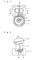
- Fig. 1 shows a plan view of an exhaust gas recirculation (EGR) cooler switching valve to which the present flow path switching valve is applied
- Fig. 2 shows a front elevational view thereof
- Fig. 3 shows a cross sectional view thereof.
- a valve passage 6 penetrating vertically is formed within a housing 1.
- a valve body 7 is arranged within the valve passage 6 so as to be freely opened and closed via a valve axis 8.
- An inlet port 2 is formed in an upper portion of the valve passage 6 so as to be open to an upper side, a lower portion of the valve passage 6 is separated into two parts by a partition wall 5 provided vertically in a center portion, and a first outlet port 3 and a second outlet port 4 are formed so as to be open to a lower side.
- the valve body 7 has a shaft mounting portion 7c for fixing the valve axis 8 in a center portion thereof, and is formed such that two valve wing portions 7a and 7b are extended symmetrically in both sides of the shaft mounting portion 7c. These two valve wing portions 7a and 7b are formed, as shown in Figs.
- a contact portion 12 with which the valve wing portion 7a is brought into contact at a time of being closed is formed in a stepped shape, in a side of the first outlet port, and a contact portion 13 with which another valve wing portion 7b is brought into contact with at a time of being closed is formed in a stepped shape, in a side of another second outlet port.
- the valve body 7 and an inner side of the valve passage 6 are formed such that in the case that the first outlet port 3 is closed, the valve wing portion 7a of the valve body 7 is brought into contact with the contact portion 12 and the valve wing portion 7b is brought into contact with a side surface of the partition wall 5 so as to completely close the side of the first outlet port.
- valve body 7 and the inner side of the valve passage 6 are formed such that in the case that the second outlet port 4 is closed, the valve wing portion 7b of the valve body 7 is brought into contact with the contact portion 13 and the valve wing portion 7a is brought into contact with the side surface of the partition wall 5 so as to completely close the side of the second outlet port.
- the switching valve structured such that the valve passage 6 is changed over by using the valve body 7 formed in the approximately L shape in the side view, as mentioned below, it is possible to make the housing 1 compact, and it is possible to make a stroke of the actuator 10 driving the valve body so as to open and close the valve body short.
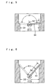
- valve length h1 of the valve body 34 it is necessary to make a valve length h1 of the valve body 34 longer than one half of an inner diameter D1 of the valve passage, and shorter than 2 ⁇ D ⁇ 1 / 2. Further, it is intended to make the valve length h1 shorter so as to make a shape of the housing compact, a rotation angle ⁇ 1 of the valve body 34 becomes larger far over 90 degree, and the stroke of the actuator becomes longer.
- a rotation angle ⁇ 2 of a valve body 44 is made small, that is, less than 90 degree, a valve length h2 of the valve body 44 becomes longer than 2 ⁇ D ⁇ 2 / 2 (D2 is an inner diameter of the valve passage), and there is generated a problem that a height of the housing is increased and the housing is made large.
- the length h of the valve wing portions 7a and 7b in the valve body 7 becomes approximately the same length as one half of the inner diameter D of the valve passage 6, and the rotation angle ⁇ of the valve body 7 becomes small, that is, less than 90 degree, it is possible to make the stroke of the actuator 10 shorter than that of Fig. 5 , and it is possible to make the housing more compact than that of Fig 6 .
- valve body 7 is fixed to the valve axis 8, and both end portions of the valve axis 8 are fitted and inserted to a bearing attached to a side wall portion of the housing 1, and can rotate within a range of the rotation angle ⁇ in the valve passage 6.
- Fig. 3 when rotating the valve body 7 to a left side, the valve wing portion 7a of the valve body 7 is brought into contact with the contact portion 12, and the valve wing portion 7b is brought into contact with the partition wall 5, whereby the first outlet port 3 is closed, and the second outlet port 4 is communicated with the inlet port 2.
- Fig. 3 when rotating the valve body 7 to a left side, the valve wing portion 7a of the valve body 7 is brought into contact with the contact portion 12, and the valve wing portion 7b is brought into contact with the partition wall 5, whereby the first outlet port 3 is closed, and the second outlet port 4 is communicated with the inlet port 2.
- valve wing portion 7a of the valve body 7 when rotating the valve body 7 to a right side, the valve wing portion 7a of the valve body 7 is brought into contact with the partition wall 5, and the valve wing portion 7b is brought into contact with the contact portion 13, whereby the second outlet port 4 is closed, and the first outlet port 3 is communicated with the inlet port 2.
- valve axis 8 protrudes to an outer side of the housing 1, and a link member 9 is fixed to a leading end thereof.
- a negative pressure type actuator 10 is mounted to an outer side of the housing 1, and a leading end of a rod 11 corresponding to an output shaft of the actuator 10 is connected to a leading end of the link member 9, whereby the structure is made such that when the rod 11 is moved in an axial direction in accordance with an operation of the actuator 10, the valve axis 8 is rotated via the link member 9 and the valve body 7 is operated so as to open and close.
- the actuator 10 has a diaphragm chamber provided with a diaphragm in, and is operated so as to move the rod 11 connected to the diaphragm in an axial direction by introducing the negative pressure to the diaphragm chamber.
- a motor-driven actuator such as an electric motor, an electromagnetic solenoid or the like, in addition to the negative type as mentioned above.
- the EGR cooler switching valve structured in the manner mentioned above is used, for example, in an EGR apparatus with EGR cooler for a diesel engine (not shown), and the housing 1 is mounted to an intake system of the engine such that the inlet port 2 is connected to the main EGR passage, the first outlet port 3 is connected to the EGR cooler passage, and the second outlet port 4 is connected to the bypass passage. Further, for example, at an engine starting time and a cold time when the temperature of the cooling water is low, the valve body 7 closes the first outlet port 3, communicates the second outlet port 4 with the inlet port 2, and becomes in a state of recirculating the exhaust gas directly to the intake manifold through the bypass passage without passing through the EGR cooler, as shown in Fig. 3 .
- the actuator 10 when the temperature of the cooling water is increased to a predetermined temperature or more, the actuator 10 is operated, and the valve axis 8 is rotated in a counterclockwise direction as shown in Fig. 4 , closes the second outlet port 4, communicates the first outlet port 3 with the inlet port 2, and becomes in a state of recirculating the exhaust gas to the intake manifold under a condition that the exhaust gas is temporarily passed through the EGR cooler and cooled.
- valve body 7 of the EGR cooler switching valve is structured such that one valve wing portion 7a or 7b is brought into contact with the contact portions 12 and 13 of the inner wall in the valve passage 6 and another valve wing portion 7a or 7b is brought into contact with the side surface of the partition wall 5 so as to open and close the valve, the port to be closed can be securely closed without generating the leakage of the fluid.
- the valve wing portions 7a and 7b are brought into contact with the contact portions 12 and 13 of the inner wall and the side surface of the partition wall 5 by the surfaces, it is possible to securely close the passage in the closing side.
- the structure is made such that one port in the upper side is set to the inlet port 2, and two ports in the lower side are set to the outlet ports 3 and 4, however, the structure may be reversely made such that one port in the upper side is set to the outlet port, and two ports in the lower side are set to the inlet ports.
- the structure is made such that the changing operation is carried out by bringing the valve wing portion into contact with the side wall of the partition wall, or bringing the valve wing portion into contact with the contact portion of the inner wall, however, the structure may be made such that the passage is closed by a very small gap without the actual contact.
- the leakage of the fluid in this case can be restricted to a level with no problem in view of the function in the flow passage in which the switching valve is used, and it is possible to expect an effect that the leakage can be reduced.
- valve body formed in the L-shaped side view and having the valve wing portions in both sides it is possible to set the rotation angle of the valve body at a time of changing over two ports small, that is, less than 90 degree, whereby it is possible to make the operation stroke of the actuator short.
- the length of the valve wing portion becomes long, and the shape of the housing is made large, however, in the present flow path switching valve, since it is possible to make the length of one valve wing portion short approximately to the radius of the valve passage, and this length does not have an influence on the rotation angle of the valve body, it is possible to make the shape of the housing compact. Further, it is possible to omit the working of the seal portion on the inner wall by arranging the stepped contact portion on the inner wall.
Description
- The present invention relates to a flow path switching valve which is applied to an EGR cooler switching valve or the like for changing over an EGR cooler, and changes over a fluid from one direction to any of two directions or changes over the fluid from any of two directions to one direction.
- For example, in an exhaust gas recirculation (EGR) employed in a diesel engine or the like, in the case that an exhaust gas having a high temperature is circulated to an intake side as it is, the exhaust gas in a state of being expanded at a high temperature is supplied to an intake manifold. Accordingly, there is a problem such that a rate of the exhaust gas within a cylinder is increased, whereby an amount of air within the cylinder is reduced and a combustion efficiency is deteriorated, and an exhaust gas component such as NOx or the like is deteriorated.
- Accordingly, in the EGR apparatus, there has been developed an EGR apparatus with an EGR cooler in which the EGR cooler for cooling an exhaust gas on the basis of a heat exchange between the exhaust gas and a cooling water is arranged in a part of an EGR passage, and the exhaust gas having a high temperature is recirculated to an intake manifold in a state of being cooled by the EGR cooler (for example, refer to
Japanese Unexamined Patent Publication No. 2001-41110 - In the EGR apparatus with the EGR cooler, in the case that a temperature of the cooling water is low such as an engine starting time, a cold condition or the like, exhaust gas is excessively cooled, so that a combustion efficiency within the cylinder and an exhaust gas component are deteriorated. Accordingly, the structure is made such that the EGR exhaust gas is circulated to a bypass passage connected with bypassing a passage of the EGR cooler, at the engine starting time, a cold condition or the like in which a temperature of the engine is lower than a normal time.
- For changing over the EGR cooler between the used time and the unused time, there is employed a flow path switching valve for changing over the fluid from one direction to any of two directions or the fluid from any of two directions to one direction. The flow
path switching valve 20 is conventionally structured, as shown inFig. 7 , such that a cantilever swingtype valve body 24 is attached to a pipe passage formed by branching amain EGR passage 21 into anEGR cooler passage 22 and abypass passage 23 via avalve axis 25. - However, in the flow
path switching valve 20 using the normal swingtype valve body 24, since agap 26 is formed in a side of thevalve axis 25 in thevalve body 24, a lot of fluid leaks through thegap 26, so that there is a problem that a secure switching can not be performed. - Accordingly, for example, as described in
Japanese Unexamined Utility Model Publication No. 1-28387 - However, in the structure sealing the gap between the valve body and the passage wall in the valve apparatus mentioned above, the seal member and a peripheral structure around the seal member become complex, whereby there are problems such that a manufacturing cost is increased and a performance of the seal structure tends to be lowered due to a complex structure.
-
WO 03/085252 A2 -
US 6,286,306 B1 discloses a system for purifying exhaust gas generated by an internal combustion engine having a bypass exhaust gas passage branching from an exhaust pipe which is opened or closed by a switch-over valve. -
FR 2.811.052 - It is an object of the invention to provide a flow path switching valve according to the preamble of claim 1, which is of a simple design and allows to securely close selectively each of a passage from the first port to the second port or from the first port to the third port.
- A solution of this object is achieved by flow path switching valve according to claim 1.
- With the inventive switching valve due to the angle between the wing portions at the side of the valve body facing to the partition valve being smaller than 90 degree one of the wing portions closes one of the passages and the other of the wing portions closes a gap between it and the partition wall by contacting the partition wall.
- Appended sub-claims are directed towards advantageous embodiments of the inventive valve.
- In accordance with the flow path switching valve of the present invention, for example, in the case of using in a state in which the first port is set to an outlet port for the fluid, and the second and third ports are set to inlet ports, the valve body is rotated via the valve axis in such a manner as to change over the fluid from any of the inlet ports to the outlet port. At this time, the valve body formed in an approximately L shape in a side view rotates around the valve axis positioned near the partition wall between two inlet ports, closes one of the inlet ports by one valve wing portion, and brings or substantially brings another valve wing portion into contact with the partition wall, thereby performing a change-over operation so as to open another inlet port.
- Accordingly, it is possible to close the gap between the valve axis and the partition wall by the valve wing portion at a time of changing over without using such a complex seal structure as the conventional switching valve, and it is possible to change over the valve with hardly generating the leakage of the fluid.
- Further, since the valve body formed in the approximately L shape in the side view and having the valve wing portions in both sides is used, it is possible to set an angle of rotation of the valve body at a time of changing over two ports to be less than 90 degree, whereby it is possible to make an operation stroke of the actuator short.
- Further, since a length of the valve wing portion can be set approximately to a radius of the valve passage without exerting an influence on an operating angle of the valve due to the length of the valve wing portion, that is, in a state in which the operating angle of the valve is set small, that is, less than 90 degree, it is possible to make the shape of the housing compact.
-
-
Fig. 1 is a plan view of a flow path switching valve showing one embodiment in accordance with the present invention; -
Fig. 2 is a front elevational view of the flow path switching valve; -
Fig. 3 is a cross sectional view along a line III-III inFig. 1 ; -
Fig. 4 is a cross sectional view of a state in which a valve body is changed over; -
Fig. 5 is a cross sectional view of a switching valve in accordance with a comparative embodiment; -
Fig. 6 is a cross sectional view of a switching valve in accordance with a comparative embodiment; and -
Fig. 7 is a cross sectional view of a flow path switching valve in accordance with a prior art. - A description will be given below of the present invention on the basis of an embodiment shown in the accompanying drawings. In this case, this invention is not limited to the embodiment. Every modifications within the features of claim and subjects equivalent to the features are contained in the scope of claim.
-
Fig. 1 shows a plan view of an exhaust gas recirculation (EGR) cooler switching valve to which the present flow path switching valve is applied,Fig. 2 shows a front elevational view thereof, andFig. 3 shows a cross sectional view thereof. As shown inFig. 3 , avalve passage 6 penetrating vertically is formed within a housing 1. Avalve body 7 is arranged within thevalve passage 6 so as to be freely opened and closed via avalve axis 8. - An
inlet port 2 is formed in an upper portion of thevalve passage 6 so as to be open to an upper side, a lower portion of thevalve passage 6 is separated into two parts by apartition wall 5 provided vertically in a center portion, and afirst outlet port 3 and asecond outlet port 4 are formed so as to be open to a lower side. Thevalve body 7 has ashaft mounting portion 7c for fixing thevalve axis 8 in a center portion thereof, and is formed such that twovalve wing portions shaft mounting portion 7c. These twovalve wing portions Figs. 3 and 4 , in an approximately L shaped open shape in a front view or a side view in such a manner that a pinched angle (an inner angle) having a predetermined angle θ is provided between both sides of theshaft mounting portion 7c. This angle θ is set to a predetermined angle less than 90 degree. - On the other hand, in the
valve passage 6 within a housing 1, acontact portion 12 with which thevalve wing portion 7a is brought into contact at a time of being closed is formed in a stepped shape, in a side of the first outlet port, and acontact portion 13 with which anothervalve wing portion 7b is brought into contact with at a time of being closed is formed in a stepped shape, in a side of another second outlet port. Further, thevalve body 7 and an inner side of thevalve passage 6 are formed such that in the case that thefirst outlet port 3 is closed, thevalve wing portion 7a of thevalve body 7 is brought into contact with thecontact portion 12 and thevalve wing portion 7b is brought into contact with a side surface of thepartition wall 5 so as to completely close the side of the first outlet port. In the same manner, thevalve body 7 and the inner side of thevalve passage 6 are formed such that in the case that thesecond outlet port 4 is closed, thevalve wing portion 7b of thevalve body 7 is brought into contact with thecontact portion 13 and thevalve wing portion 7a is brought into contact with the side surface of thepartition wall 5 so as to completely close the side of the second outlet port. - In the switching valve structured such that the
valve passage 6 is changed over by using thevalve body 7 formed in the approximately L shape in the side view, as mentioned below, it is possible to make the housing 1 compact, and it is possible to make a stroke of theactuator 10 driving the valve body so as to open and close the valve body short. - In other words, as shown in
Fig. 5 showing a comparative embodiment, in the case of using aflat valve body 34, it is necessary to make a valve length h1 of thevalve body 34 longer than one half of an inner diameter D1 of the valve passage, and shorter than
valve body 34 becomes larger far over 90 degree, and the stroke of the actuator becomes longer. - On the other hand, as shown in
Fig. 6 showing a comparative embodiment, in the case that a rotation angle θ2 of avalve body 44 is made small, that is, less than 90 degree, a valve length h2 of thevalve body 44 becomes longer than
- On the contrary, in the flow path switching valve in accordance with the present invention, the length h of the
valve wing portions valve body 7 becomes approximately the same length as one half of the inner diameter D of thevalve passage 6, and the rotation angle θ of thevalve body 7 becomes small, that is, less than 90 degree, it is possible to make the stroke of theactuator 10 shorter than that ofFig. 5 , and it is possible to make the housing more compact than that ofFig 6 . - The
valve body 7 is fixed to thevalve axis 8, and both end portions of thevalve axis 8 are fitted and inserted to a bearing attached to a side wall portion of the housing 1, and can rotate within a range of the rotation angle θ in thevalve passage 6. Further, as shown inFig. 3 , when rotating thevalve body 7 to a left side, thevalve wing portion 7a of thevalve body 7 is brought into contact with thecontact portion 12, and thevalve wing portion 7b is brought into contact with thepartition wall 5, whereby thefirst outlet port 3 is closed, and thesecond outlet port 4 is communicated with theinlet port 2. Further, as shown inFig. 4 , when rotating thevalve body 7 to a right side, thevalve wing portion 7a of thevalve body 7 is brought into contact with thepartition wall 5, and thevalve wing portion 7b is brought into contact with thecontact portion 13, whereby thesecond outlet port 4 is closed, and thefirst outlet port 3 is communicated with theinlet port 2. - One end of the
valve axis 8 protrudes to an outer side of the housing 1, and alink member 9 is fixed to a leading end thereof. A negativepressure type actuator 10 is mounted to an outer side of the housing 1, and a leading end of arod 11 corresponding to an output shaft of theactuator 10 is connected to a leading end of thelink member 9, whereby the structure is made such that when therod 11 is moved in an axial direction in accordance with an operation of theactuator 10, thevalve axis 8 is rotated via thelink member 9 and thevalve body 7 is operated so as to open and close. Theactuator 10 has a diaphragm chamber provided with a diaphragm in, and is operated so as to move therod 11 connected to the diaphragm in an axial direction by introducing the negative pressure to the diaphragm chamber. In this case, as the actuator, it is possible to use a motor-driven actuator such as an electric motor, an electromagnetic solenoid or the like, in addition to the negative type as mentioned above. - The EGR cooler switching valve structured in the manner mentioned above is used, for example, in an EGR apparatus with EGR cooler for a diesel engine (not shown), and the housing 1 is mounted to an intake system of the engine such that the
inlet port 2 is connected to the main EGR passage, thefirst outlet port 3 is connected to the EGR cooler passage, and thesecond outlet port 4 is connected to the bypass passage. Further, for example, at an engine starting time and a cold time when the temperature of the cooling water is low, thevalve body 7 closes thefirst outlet port 3, communicates thesecond outlet port 4 with theinlet port 2, and becomes in a state of recirculating the exhaust gas directly to the intake manifold through the bypass passage without passing through the EGR cooler, as shown inFig. 3 . Further, when the temperature of the cooling water is increased to a predetermined temperature or more, theactuator 10 is operated, and thevalve axis 8 is rotated in a counterclockwise direction as shown inFig. 4 , closes thesecond outlet port 4, communicates thefirst outlet port 3 with theinlet port 2, and becomes in a state of recirculating the exhaust gas to the intake manifold under a condition that the exhaust gas is temporarily passed through the EGR cooler and cooled. - As mentioned above, as shown in
Figs. 3 and 4 , since thevalve body 7 of the EGR cooler switching valve is structured such that onevalve wing portion contact portions valve passage 6 and anothervalve wing portion partition wall 5 so as to open and close the valve, the port to be closed can be securely closed without generating the leakage of the fluid. In particular, since thevalve wing portions contact portions partition wall 5 by the surfaces, it is possible to securely close the passage in the closing side. Further, even when the contact portion in the valve body and the contact portion are worn due to the vibration or the like, it is possible to securely close the passage in the closing side without generating the leakage of the fluid, and it is possible to change over the flow path well. Further, as mentioned above, it is possible to achieve a compact structure of the housing and a compact structure of the actuator. - In this case, in the embodiment mentioned above, as shown in
Figs. 3 and 4 , the structure is made such that one port in the upper side is set to theinlet port 2, and two ports in the lower side are set to theoutlet ports - Further, in the embodiment mentioned above, the structure is made such that the changing operation is carried out by bringing the valve wing portion into contact with the side wall of the partition wall, or bringing the valve wing portion into contact with the contact portion of the inner wall, however, the structure may be made such that the passage is closed by a very small gap without the actual contact. The leakage of the fluid in this case can be restricted to a level with no problem in view of the function in the flow passage in which the switching valve is used, and it is possible to expect an effect that the leakage can be reduced.
- As mentioned above, in accordance with the flow path switching valve of the present invention, it is possible to change over the valve by closing the gap between the valve axis and the partition wall at a time of changing over while generating no leakage of the fluid or restricting the leakage, without using the complex seal structure such as the conventional switching valve. Further, since the valve body formed in the L-shaped side view and having the valve wing portions in both sides, it is possible to set the rotation angle of the valve body at a time of changing over two ports small, that is, less than 90 degree, whereby it is possible to make the operation stroke of the actuator short. Further, in the conventional switching valve, when the rotation angle of the valve body is made small, the length of the valve wing portion becomes long, and the shape of the housing is made large, however, in the present flow path switching valve, since it is possible to make the length of one valve wing portion short approximately to the radius of the valve passage, and this length does not have an influence on the rotation angle of the valve body, it is possible to make the shape of the housing compact. Further, it is possible to omit the working of the seal portion on the inner wall by arranging the stepped contact portion on the inner wall.
Claims (5)
- A flow path switching valve comprising:(a) a first port (2) provided in a valve passage (6) within a housing (1);(b) a second port (3) provided in said valve passage (6) so as to be communicated with said first port;(c) a third port (4) provided in said valve passage (6) so as to be communicated with said first port (2); andsaid flow path switching valve changing over said second port and said third port with respect to said first port so as to communicate,
wherein a partition wall (5) is formed between said second port (3) and said third port (4), a valve axis is rotably supported to a position near said partition wall (5), a valve body (7) having a shaft mounting portion (7c) in its center portion and valve wing portions (7a, 7b) extending at both sides of the shaft mounting portion (7c), to which the valve axis is fixed, in an approximately L-shape in a side view is mounted in such a manner as to close with one of the wing portions (7a, 7b) a passage from the first port (2) to the second port (3) in one of its closing positions and after being rotated into its other closing position to close with its other wing portion (7b) a passage from the first port (2) to the third port (4),
characterized in that
an angle less than 90 degree and larger than 0 degree is formed between the wing portions (7a, 7b) at a side of the valve body (7) facing to the partition wall (5), whereby when one of the wing portions closes one of the passages the other of the wing portions closes a gap between it and the partition wall (5). - A flow path switching valve according to claim 1, wherein the respective wing portion (7a, 7b), which closes a gap between it and the partition wall (5), is in contact with a side surface of the partition wall.
- A flow path switching valve according to claim 1 or 2, wherein a portion near a leading end portion of the valve wing portion (7a, 7b) in a close side is brought into contact with a stepped contact portion (12, 13) provided on an inner surface of said valve passage (6) when the valve body is in one of its closing positions.
- A flow path switching valve according to any of claims 1 to 3, wherein the valve body (7) completely closes in its respective closing positions a respective one of the passages from the first port (2) to the second port (3) or the first port (2) to the third port (4).
- A flow path switching valve according to any of claims 1 to 3, wherein an end portion of said valve axis is protruded to an outer side of said housing (1) and a rod (11) of an actuator (10) change-over driving said valve body (7) is connected to an end portion of said valve axis via a link.member.
Applications Claiming Priority (2)
| Application Number | Priority Date | Filing Date | Title |
|---|---|---|---|
| JP2002355630A JP2004190693A (en) | 2002-12-06 | 2002-12-06 | Flow passage switching valve |
| JP2002355630 | 2002-12-06 |
Publications (4)
| Publication Number | Publication Date |
|---|---|
| EP1426604A2 EP1426604A2 (en) | 2004-06-09 |
| EP1426604A3 EP1426604A3 (en) | 2006-12-13 |
| EP1426604B1 EP1426604B1 (en) | 2010-05-12 |
| EP1426604B9 true EP1426604B9 (en) | 2010-09-08 |
Family
ID=32310767
Family Applications (1)
| Application Number | Title | Priority Date | Filing Date |
|---|---|---|---|
| EP03025779A Expired - Lifetime EP1426604B9 (en) | 2002-12-06 | 2003-11-11 | Flow path switching valve |
Country Status (4)
| Country | Link |
|---|---|
| EP (1) | EP1426604B9 (en) |
| JP (1) | JP2004190693A (en) |
| DE (1) | DE60332518D1 (en) |
| ES (1) | ES2344550T3 (en) |
Families Citing this family (24)
| Publication number | Priority date | Publication date | Assignee | Title |
|---|---|---|---|---|
| JP4324967B2 (en) * | 2004-07-23 | 2009-09-02 | 株式会社デンソー | Exhaust gas recirculation control device |
| CA2578989C (en) | 2004-09-03 | 2014-02-25 | Elcam Medical Agricultural Cooperative Association Ltd. | Stopcock |
| JP2008528874A (en) * | 2005-02-03 | 2008-07-31 | ベール ゲーエムベーハー ウント コー カーゲー | Exhaust gas heat exchanger especially for automobiles |
| ES2233217B1 (en) * | 2005-02-08 | 2007-03-16 | Dayco Ensa, S.L. | BY-PASS VALVE. |
| JP2007113395A (en) * | 2005-10-17 | 2007-05-10 | Aisan Ind Co Ltd | Exhaust valve |
| DE102007007111A1 (en) * | 2007-02-13 | 2008-08-14 | Siemens Ag | flap valve |
| FR2916255B1 (en) * | 2007-05-18 | 2014-06-27 | Faurecia Sys Echappement | THREE-WAY VALVE FOR EXHAUST LINE OF MOTOR VEHICLE |
| FR2919674B1 (en) * | 2007-07-31 | 2009-10-02 | Renault Sas | DEVICE FOR ORIENTATION AND REGULATION OF EXHAUST GAS OF A HEAT ENGINE IN AN EXHAUST GAS RECIRCULATION CIRCUIT CALLED EGR TO AIR INTAKE |
| DE102007048824B4 (en) * | 2007-10-10 | 2018-02-22 | Mahle International Gmbh | Heat exchanger, in particular for exhaust gas cooling |
| TW200916042A (en) | 2007-10-11 | 2009-04-16 | Panasonic Corp | Dish washing/drying machine |
| JP4553023B2 (en) * | 2008-03-21 | 2010-09-29 | 株式会社デンソー | Exhaust gas switching valve |
| JP2011111963A (en) * | 2009-11-26 | 2011-06-09 | Calsonic Kansei Corp | Switching valve structure |
| JP5439258B2 (en) * | 2010-03-31 | 2014-03-12 | 株式会社ユタカ技研 | Waste heat recovery device |
| KR101016190B1 (en) * | 2010-04-12 | 2011-02-24 | 주식회사 유니크 | Bypass valve for vehicle |
| EP2623765B1 (en) | 2012-02-01 | 2015-04-08 | Continental Automotive GmbH | Exhaust gas control device for a combustion engine |
| CN102966758B (en) * | 2012-11-08 | 2014-04-02 | 佛山市科皓燃烧设备制造有限公司 | Flange type three-way butterfly valve |
| US10711788B2 (en) | 2015-12-17 | 2020-07-14 | Wayne/Scott Fetzer Company | Integrated sump pump controller with status notifications |
| EP3390870A4 (en) * | 2015-12-18 | 2019-10-02 | Padmini VNA Mechatronics Pvt. Ltd. | Double flapped switch valve for controlling the re-circulation exhaust passage |
| US10238326B2 (en) | 2016-08-04 | 2019-03-26 | Elcam Medical Agricultural Cooperative Association Ltd. | Flushable fluid handling assembly |
| JP6695816B2 (en) * | 2017-02-23 | 2020-05-20 | 株式会社豊田自動織機 | Flow path switching valve |
| USD893552S1 (en) | 2017-06-21 | 2020-08-18 | Wayne/Scott Fetzer Company | Pump components |
| KR102630666B1 (en) | 2017-06-22 | 2024-01-29 | 엘캠 메디컬 애그리컬처럴 코오퍼레이티브 어소시에이션 리미티드 | Closed stopcock |
| USD890211S1 (en) | 2018-01-11 | 2020-07-14 | Wayne/Scott Fetzer Company | Pump components |
| DE102019105975A1 (en) | 2019-03-08 | 2020-09-10 | Grohe Ag | Sanitary fitting with a two-way valve |
Family Cites Families (5)
| Publication number | Priority date | Publication date | Assignee | Title |
|---|---|---|---|---|
| DE3700219A1 (en) * | 1987-01-07 | 1988-07-21 | Teves Gmbh Alfred | ELECTROMAGNETICALLY OPERABLE 3/2-WAY VALVE |
| US6286306B1 (en) * | 1999-02-08 | 2001-09-11 | Honda Giken Kogyo Kabushiki Kaisha | Exhaust gas purification system of internal combustion engine |
| FR2790300B1 (en) * | 1999-02-26 | 2001-04-27 | Mark Iv Systemes Moteurs Sa | VALVE ASSEMBLY AND FLUID CIRCULATION AND DISPENSING DEVICE COMPRISING SUCH AN ASSEMBLY |
| DE10031991B4 (en) * | 2000-06-30 | 2004-02-05 | Valeo Klimasysteme Gmbh | damper |
| FR2838500B1 (en) * | 2002-04-10 | 2004-11-19 | Johnson Contr Automotive Elect | BY-PASS VALVE FOR A GAS COOLING DEVICE OF AN INTERNAL COMBUSTION ENGINE |
-
2002
- 2002-12-06 JP JP2002355630A patent/JP2004190693A/en not_active Withdrawn
-
2003
- 2003-11-11 ES ES03025779T patent/ES2344550T3/en not_active Expired - Lifetime
- 2003-11-11 DE DE60332518T patent/DE60332518D1/en not_active Expired - Lifetime
- 2003-11-11 EP EP03025779A patent/EP1426604B9/en not_active Expired - Lifetime
Also Published As
| Publication number | Publication date |
|---|---|
| ES2344550T3 (en) | 2010-08-31 |
| JP2004190693A (en) | 2004-07-08 |
| DE60332518D1 (en) | 2010-06-24 |
| EP1426604A2 (en) | 2004-06-09 |
| EP1426604B1 (en) | 2010-05-12 |
| EP1426604A3 (en) | 2006-12-13 |
Similar Documents
| Publication | Publication Date | Title |
|---|---|---|
| EP1426604B9 (en) | Flow path switching valve | |
| KR101387627B1 (en) | Exhaust-Gas Recirculation Valve | |
| US5740785A (en) | Two way-high pressure loop, exhaust gas recirculation valve | |
| EP2556239B1 (en) | Bypass valve for vehicle | |
| US11149862B2 (en) | Valve device and cooling system | |
| JP5283386B2 (en) | Bypass valve | |
| US11085548B2 (en) | Valve device | |
| US11098808B2 (en) | Control valve | |
| JP2007040136A (en) | Exhaust gas recirculation system of internal combustion engine with supercharger | |
| CN111750137B (en) | Control valve | |
| CN108952933A (en) | control valve | |
| JP5699662B2 (en) | Exhaust device for internal combustion engine | |
| JP2008527248A (en) | Vehicle with exhaust recirculation system | |
| JP2017008870A (en) | Low-pressure egr device | |
| KR101399417B1 (en) | Bypass valve assembly for egr cooler | |
| CN212583845U (en) | Three-way control valve and engine air inlet and exhaust system | |
| CA2730125C (en) | Exhaust gas recirculation butterfly valve | |
| EP1213468A2 (en) | Open manifold back pressure valve exhaust gas recirculation system | |
| US5730586A (en) | Supercharger with integral by-pass passage | |
| JP6059236B2 (en) | Exhaust gas circulation valve of an engine such as an automobile engine | |
| JP2007154907A (en) | Valve opening and closing controller | |
| JPH0345220B2 (en) | ||
| JPS6135709Y2 (en) | ||
| EP1923550A2 (en) | Bypass assembly for a charge-air cooler | |
| JP2015522764A (en) | Fluid circulation valve |
Legal Events
| Date | Code | Title | Description |
|---|---|---|---|
| PUAI | Public reference made under article 153(3) epc to a published international application that has entered the european phase |
Free format text: ORIGINAL CODE: 0009012 |
|
| 17P | Request for examination filed |
Effective date: 20031111 |
|
| AK | Designated contracting states |
Kind code of ref document: A2 Designated state(s): AT BE BG CH CY CZ DE DK EE ES FI FR GB GR HU IE IT LI LU MC NL PT RO SE SI SK TR |
|
| AX | Request for extension of the european patent |
Extension state: AL LT LV MK |
|
| PUAL | Search report despatched |
Free format text: ORIGINAL CODE: 0009013 |
|
| AK | Designated contracting states |
Kind code of ref document: A3 Designated state(s): AT BE BG CH CY CZ DE DK EE ES FI FR GB GR HU IE IT LI LU MC NL PT RO SE SI SK TR |
|
| AX | Request for extension of the european patent |
Extension state: AL LT LV MK |
|
| RIC1 | Information provided on ipc code assigned before grant |
Ipc: F02M 25/07 20060101AFI20040305BHEP Ipc: F16K 11/052 20060101ALI20061106BHEP |
|
| 17Q | First examination report despatched |
Effective date: 20070618 |
|
| AKX | Designation fees paid |
Designated state(s): DE ES FR GB IT |
|
| GRAP | Despatch of communication of intention to grant a patent |
Free format text: ORIGINAL CODE: EPIDOSNIGR1 |
|
| GRAS | Grant fee paid |
Free format text: ORIGINAL CODE: EPIDOSNIGR3 |
|
| GRAA | (expected) grant |
Free format text: ORIGINAL CODE: 0009210 |
|
| AK | Designated contracting states |
Kind code of ref document: B1 Designated state(s): DE ES FR GB IT |
|
| REG | Reference to a national code |
Ref country code: GB Ref legal event code: FG4D |
|
| REF | Corresponds to: |
Ref document number: 60332518 Country of ref document: DE Date of ref document: 20100624 Kind code of ref document: P |
|
| REG | Reference to a national code |
Ref country code: ES Ref legal event code: FG2A Ref document number: 2344550 Country of ref document: ES Kind code of ref document: T3 |
|
| PLBE | No opposition filed within time limit |
Free format text: ORIGINAL CODE: 0009261 |
|
| STAA | Information on the status of an ep patent application or granted ep patent |
Free format text: STATUS: NO OPPOSITION FILED WITHIN TIME LIMIT |
|
| PG25 | Lapsed in a contracting state [announced via postgrant information from national office to epo] |
Ref country code: IT Free format text: LAPSE BECAUSE OF FAILURE TO SUBMIT A TRANSLATION OF THE DESCRIPTION OR TO PAY THE FEE WITHIN THE PRESCRIBED TIME-LIMIT Effective date: 20100512 |
|
| 26N | No opposition filed |
Effective date: 20110215 |
|
| REG | Reference to a national code |
Ref country code: DE Ref legal event code: R097 Ref document number: 60332518 Country of ref document: DE Effective date: 20110214 |
|
| GBPC | Gb: european patent ceased through non-payment of renewal fee |
Effective date: 20101111 |
|
| PG25 | Lapsed in a contracting state [announced via postgrant information from national office to epo] |
Ref country code: GB Free format text: LAPSE BECAUSE OF NON-PAYMENT OF DUE FEES Effective date: 20101111 |
|
| REG | Reference to a national code |
Ref country code: FR Ref legal event code: PLFP Year of fee payment: 13 |
|
| PGFP | Annual fee paid to national office [announced via postgrant information from national office to epo] |
Ref country code: ES Payment date: 20151014 Year of fee payment: 13 Ref country code: FR Payment date: 20151008 Year of fee payment: 13 |
|
| REG | Reference to a national code |
Ref country code: FR Ref legal event code: ST Effective date: 20170731 |
|
| PG25 | Lapsed in a contracting state [announced via postgrant information from national office to epo] |
Ref country code: FR Free format text: LAPSE BECAUSE OF NON-PAYMENT OF DUE FEES Effective date: 20161130 |
|
| PG25 | Lapsed in a contracting state [announced via postgrant information from national office to epo] |
Ref country code: ES Free format text: LAPSE BECAUSE OF NON-PAYMENT OF DUE FEES Effective date: 20161112 |
|
| REG | Reference to a national code |
Ref country code: ES Ref legal event code: FD2A Effective date: 20181121 |
|
| PGFP | Annual fee paid to national office [announced via postgrant information from national office to epo] |
Ref country code: DE Payment date: 20220930 Year of fee payment: 20 |
|
| REG | Reference to a national code |
Ref country code: DE Ref legal event code: R071 Ref document number: 60332518 Country of ref document: DE |