JP2011111963A - Switching valve structure - Google Patents
Switching valve structure Download PDFInfo
- Publication number
- JP2011111963A JP2011111963A JP2009268690A JP2009268690A JP2011111963A JP 2011111963 A JP2011111963 A JP 2011111963A JP 2009268690 A JP2009268690 A JP 2009268690A JP 2009268690 A JP2009268690 A JP 2009268690A JP 2011111963 A JP2011111963 A JP 2011111963A
- Authority
- JP
- Japan
- Prior art keywords
- exhaust pipe
- exhaust
- valve
- pipe
- switching valve
- Prior art date
- Legal status (The legal status is an assumption and is not a legal conclusion. Google has not performed a legal analysis and makes no representation as to the accuracy of the status listed.)
- Pending
Links
- 238000003780 insertion Methods 0.000 claims abstract description 28
- 230000037431 insertion Effects 0.000 claims abstract description 28
- 238000002485 combustion reaction Methods 0.000 claims description 9
- 238000004519 manufacturing process Methods 0.000 abstract description 4
- 239000007789 gas Substances 0.000 description 59
- 238000011084 recovery Methods 0.000 description 20
- 239000000498 cooling water Substances 0.000 description 13
- 238000011144 upstream manufacturing Methods 0.000 description 8
- 239000003054 catalyst Substances 0.000 description 3
- 239000000446 fuel Substances 0.000 description 3
- 238000005304 joining Methods 0.000 description 3
- 230000002093 peripheral effect Effects 0.000 description 3
- 238000003466 welding Methods 0.000 description 3
- CURLTUGMZLYLDI-UHFFFAOYSA-N Carbon dioxide Chemical compound O=C=O CURLTUGMZLYLDI-UHFFFAOYSA-N 0.000 description 2
- 230000007423 decrease Effects 0.000 description 2
- 230000000694 effects Effects 0.000 description 2
- 238000010438 heat treatment Methods 0.000 description 2
- 238000000034 method Methods 0.000 description 2
- 238000010248 power generation Methods 0.000 description 2
- 238000003825 pressing Methods 0.000 description 2
- 230000003584 silencer Effects 0.000 description 2
- XLYOFNOQVPJJNP-UHFFFAOYSA-N water Substances O XLYOFNOQVPJJNP-UHFFFAOYSA-N 0.000 description 2
- 241001272720 Medialuna californiensis Species 0.000 description 1
- 229910002092 carbon dioxide Inorganic materials 0.000 description 1
- 239000001569 carbon dioxide Substances 0.000 description 1
- 238000005266 casting Methods 0.000 description 1
- 239000002826 coolant Substances 0.000 description 1
- 230000006866 deterioration Effects 0.000 description 1
- 238000010586 diagram Methods 0.000 description 1
- 238000004880 explosion Methods 0.000 description 1
- 239000002803 fossil fuel Substances 0.000 description 1
- 239000000203 mixture Substances 0.000 description 1
- 230000001105 regulatory effect Effects 0.000 description 1
- 238000009423 ventilation Methods 0.000 description 1
- 239000002918 waste heat Substances 0.000 description 1
Images
Classifications
-
- Y—GENERAL TAGGING OF NEW TECHNOLOGICAL DEVELOPMENTS; GENERAL TAGGING OF CROSS-SECTIONAL TECHNOLOGIES SPANNING OVER SEVERAL SECTIONS OF THE IPC; TECHNICAL SUBJECTS COVERED BY FORMER USPC CROSS-REFERENCE ART COLLECTIONS [XRACs] AND DIGESTS
- Y02—TECHNOLOGIES OR APPLICATIONS FOR MITIGATION OR ADAPTATION AGAINST CLIMATE CHANGE
- Y02T—CLIMATE CHANGE MITIGATION TECHNOLOGIES RELATED TO TRANSPORTATION
- Y02T10/00—Road transport of goods or passengers
- Y02T10/10—Internal combustion engine [ICE] based vehicles
- Y02T10/12—Improving ICE efficiencies
Landscapes
- Exhaust Silencers (AREA)
Abstract
Description
本発明は、排ガスの配管等に用いられる切替バルブ構造に関し、より詳細には、低コスト化が可能な切替バルブ構造に関する。 The present invention relates to a switching valve structure used for exhaust gas piping and the like, and more particularly to a switching valve structure capable of reducing costs.
従来、車両に搭載される内燃機関の排熱を回収し、この熱エネルギーを他の用途(暖房や発電)に利用することにより、内燃機関の燃費効率を高めている。 Conventionally, exhaust heat of an internal combustion engine mounted on a vehicle is recovered, and this heat energy is used for other purposes (heating and power generation), thereby improving the fuel efficiency of the internal combustion engine.
排熱の回収は、内燃機関の排気管の途中に排熱回収器を設け、この排熱回収器に冷却水等を流通させることにより行うことが一般的である。この場合、内燃機関の運転状態によっては、常に排熱回収器に冷却水を流通させることが適切でない場合がある。 In general, the exhaust heat is recovered by providing an exhaust heat recovery device in the middle of the exhaust pipe of the internal combustion engine and circulating cooling water or the like through the exhaust heat recovery device. In this case, depending on the operating state of the internal combustion engine, it may not be appropriate to always distribute the cooling water to the exhaust heat recovery device.
そこで、排気管の途中を分岐させ、この分岐された経路の一方に排熱回収器を備え、他方はバイパス経路とする。分岐された経路は、再び合流部において一つの排気管に合流され、その後大気へと排出される。この分岐部及び合流部の少なくとも一方に、切替バルブを備えて、排熱回収器への排ガスの流量を調節することが一般的である。 Therefore, the middle of the exhaust pipe is branched, and one of the branched paths is provided with an exhaust heat recovery device, and the other is a bypass path. The branched path is joined again to one exhaust pipe at the joining part and then discharged to the atmosphere. Generally, a switching valve is provided in at least one of the branch part and the junction part to adjust the flow rate of the exhaust gas to the exhaust heat recovery device.
このように、排ガス経路中の分岐部分の流量を調整する切替バルブの構造として、駆動軸により回転駆動される切替バルブにより、二つの通路にそれぞれ連結される第1及び第2開口部を交互に開閉する切替バルブ(特許文献1参照。)が開示されている。 Thus, as a structure of the switching valve that adjusts the flow rate of the branch portion in the exhaust gas path, the first and second openings connected to the two passages are alternately arranged by the switching valve that is rotationally driven by the drive shaft. A switching valve that opens and closes (see Patent Document 1) is disclosed.
また、EGRガスクーラ及びバイパス配管の排気ガス流れの下流側に配置された排気ガス流量比調節弁を備えるEGRモジュール(特許文献2参照。)が開示されている。 In addition, an EGR module (see Patent Document 2) including an exhaust gas flow ratio control valve disposed on the downstream side of the exhaust gas flow of the EGR gas cooler and the bypass pipe is disclosed.
前述のように、排気管の経路を切り替える切替バルブ構造は、複数の流路を合流、分岐する連結部と、この連結部に備えられるバルブとから構成される。 As described above, the switching valve structure for switching the path of the exhaust pipe includes a connecting portion that joins and branches a plurality of flow paths, and a valve provided in the connecting portion.
この連結部は、バルブの構造にあわせて、プレス形成やロストワックス工法による鋳造等により、流路の配管とは異なる構造体として形成される。また、バルブに関しても、開閉動作に対するストッパーをバルブ又は連結部の構成としている。 This connecting portion is formed as a structure different from the piping of the flow path by press forming or casting by the lost wax method in accordance with the structure of the valve. Further, with respect to the valve, a stopper for the opening / closing operation is configured as a valve or a connecting portion.
そのため、連結部を排気管の構成にあわせて別部品として構成するためのコストが上昇するという問題がある。 Therefore, there exists a problem that the cost for comprising a connection part as another component according to the structure of an exhaust pipe rises.
また、バルブのストッパーとなる部品が排ガスの抵抗となってしまい、排圧が上昇して満足する性能が得られない場合があるという問題がある。 In addition, there is a problem that a part that becomes a stopper of the valve becomes a resistance of the exhaust gas, and the exhaust pressure rises and a satisfactory performance may not be obtained.
また、これら連結部及びバルブによる部品点数の増加や、排圧を低下させるため形状が複雑化し、加工コストが増加することにより、コストが上昇するという問題がある。 In addition, there is a problem that the cost increases due to an increase in the number of parts due to these connecting portions and valves, and a complicated shape due to a reduction in exhaust pressure and an increase in processing cost.
本発明はこのような問題点を鑑みてなされたものであり、コストを増加させることなく、排ガスの排圧を増加させない切替バルブ構造を提供することを目的とする。 The present invention has been made in view of such problems, and an object of the present invention is to provide a switching valve structure that does not increase the exhaust pressure without increasing the cost.
請求項1に記載の発明は、内燃機関の排ガスの通路を分岐する切替バルブ構造であって、端部に向かうにつれて拡径された拡大部を有する第1の排気管と、端部に向かうにつれて縮径されると共に、端部の一部に平坦部が形成された差込部を備えた第2の排気管及び第3の排気管と、拡大部に備えられた回転軸に支持され、第2の排気管又は第3の排気管への排ガスの流れを制限するバルブと、を備え、第2の排気管の平坦部と第3の排気管の平坦部とを向かい合わせた状態で、第2の排気管の差込部と第3の排気管の差込部とが拡大部へと挿嵌され、第3の排気管の平坦部の端部が、第2の排気管の平坦部の端部よりも第1の排気管側へと延設されることを特徴とする。 The invention according to claim 1 is a switching valve structure for branching an exhaust gas passage of an internal combustion engine, the first exhaust pipe having an enlarged portion whose diameter is enlarged toward the end portion, and as going to the end portion. The second exhaust pipe and the third exhaust pipe each having a reduced diameter and having an insertion portion in which a flat portion is formed at a part of the end portion, and a rotary shaft provided in the enlarged portion, are supported by the first And a valve for restricting the flow of exhaust gas to the second exhaust pipe or the third exhaust pipe, and in a state where the flat portion of the second exhaust pipe and the flat portion of the third exhaust pipe face each other, The insertion part of the second exhaust pipe and the insertion part of the third exhaust pipe are inserted into the enlarged part, and the end of the flat part of the third exhaust pipe is connected to the flat part of the second exhaust pipe. It is characterized by extending from the end toward the first exhaust pipe.
請求項2に記載の発明は、請求項1に記載の切替バルブ構造において、回転軸からバルブと異なる方向へ突設される突設部を備え、第3の排気管の差込部の平坦部へと突設部を当接することによって、第2の排気管への排ガスの流れを制限することを特徴とする。 According to a second aspect of the present invention, in the switching valve structure according to the first aspect of the present invention, the switching valve structure includes a projecting portion projecting in a direction different from the valve from the rotating shaft, and the flat portion of the plug portion of the third exhaust pipe It is characterized in that the flow of the exhaust gas to the second exhaust pipe is restricted by contacting the projecting portion to the side.
請求項3に記載の発明は、請求項1又は2に記載の切替バルブ構造において、バルブは、拡大部の内壁に当接することで第2の排気管への排ガスの流れを制限する第1のバルブと、バルブの回転軸からバルブと異なる方向へ突設され、第3の排気管の差込部の平坦面へと当接することで第3の排気管への排ガスの流れを規制する第2のバルブと、を備えることを特徴とする。
を特徴とする。
According to a third aspect of the present invention, there is provided the switching valve structure according to the first or second aspect, wherein the valve abuts against the inner wall of the enlarged portion to restrict the flow of the exhaust gas to the second exhaust pipe. A valve and a second protruding from the rotary shaft of the valve in a direction different from the valve and contacting the flat surface of the insertion portion of the third exhaust pipe to regulate the flow of exhaust gas to the third exhaust pipe And a valve.
It is characterized by.
請求項1に記載の発明によると、各排気管の端部を加工したもの同士を組み合わせることにより切替バルブ構造を構成するので、構成する部品を削減することができる。これにより、継手部分が必要なくなり、プレスによる鍛造品やロストワックスによる鋳物品等を別部品として形成する必要がなく、内部に抵抗となる構造が少ないため排圧を増加させないと共に、製造コストを抑えることができる。また、第3の排気管の差込部の平坦部を、第1の排気管へと延設させたので、バルブの回転軸と平坦部の端部との距離を縮小でき、バルブを閉成した側の排気管への排ガスの漏れを抑制することができる。 According to the first aspect of the present invention, the switching valve structure is configured by combining the ends of the exhaust pipes so that the components to be configured can be reduced. This eliminates the need for joint parts, eliminates the need to form forged products by pressing, cast articles from lost wax, etc. as separate parts, and does not increase exhaust pressure because there are few internal resistance structures, while reducing manufacturing costs be able to. In addition, since the flat portion of the insertion portion of the third exhaust pipe is extended to the first exhaust pipe, the distance between the rotating shaft of the valve and the end of the flat portion can be reduced, and the valve is closed. Leakage of exhaust gas to the exhaust pipe on the left side can be suppressed.
請求項2に記載の発明によると、バルブにストッパーを備えたので、構成する部品を削減しつつ、一方の排気管への排ガスの流れを完全に抑制することができる。特に、第1の排気管へと延設させた平坦部には溶接等の加工痕が残らないため、第2の排気管を完全に閉塞することができる。、 According to the second aspect of the present invention, since the valve is provided with the stopper, it is possible to completely suppress the flow of the exhaust gas to the one exhaust pipe while reducing the number of components. In particular, since a processing mark such as welding does not remain in the flat portion extended to the first exhaust pipe, the second exhaust pipe can be completely closed. ,
請求項3に記載の発明によると、バルブの作動角度を小さくすることができるので、バルブを回動させるための必要トルクが小さくなり、切替バルブ構造のコストを抑えることができると共に、排気管の構成を小型化することができる。 According to the invention described in claim 3, since the valve operating angle can be reduced, the torque required for rotating the valve is reduced, the cost of the switching valve structure can be reduced, and the exhaust pipe The configuration can be reduced in size.
以下に、本発明の実施形態について図面を用いて説明する。 Embodiments of the present invention will be described below with reference to the drawings.
<第1実施形態>
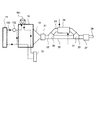
図1は、本発明の第1の実施形態のエンジン10を中心とした駆動システムの説明図である。
<First Embodiment>
FIG. 1 is an explanatory diagram of a drive system centering on an
本実施形態の駆動システムは、車両に搭載されたエンジン10により車両を駆動させる。
The drive system of this embodiment drives a vehicle by an
内燃機関としてのエンジン10は、空気と気化された化石燃料とによる混合燃料を爆発燃焼させることにより回転駆動力を得る。爆発燃焼後の排ガスは、マニホルド12、排気管20等を経て、大気へと排出される。
The
エンジン10は、エンジン10を適切な温度に保つための冷却水系統100が備えられる。冷却水系統100は、ラジエータ11、ヒータ13、ウォーターポンプ101、サーモスタット102が備えられる。
The
ウォーターポンプ101により冷却水系統100内を循環させられる冷却水は、ラジエータ11において熱交換を行うことで適切に冷却され、エンジン10を適切な温度に保つ。サーモスタット102は、冷却水温度が所定温度以下の場合に閉成し、ラジエータ11をバイパスさせることにより、エンジンの暖機を促進する。ヒータ13は、冷却水の余熱を用いて、車室内を暖房する。
The cooling water circulated in the
排気管20は、マニホルド12、触媒21、上流側管22、分岐部30、分岐管23、排熱回収器24、下流側管25、合流部31、バイパス管26、消音器27及びテールパイプ28により構成される。
The exhaust pipe 20 includes a
エンジン10から排出される排ガスは、マニホルド12を経て、触媒21により浄化される。触媒21の下流側には上流側管22が接続される。上流側管22の下流側には分岐部30が構成される。
The exhaust gas discharged from the
分岐部30は、排ガスを分岐管23に送るか、バイパス管26に送るかを切り替える切替バルブ構造40を備える。この切替バルブ構造40の詳細は後述する。
The
分岐管23は排熱回収器24が備えられる。排熱回収器24は、導入される媒体と排ガスとで熱交換を行うことによって、媒体の温度を上昇させる。
The
排熱回収器24は、通常、エンジン10の冷却水系統100に接続され、媒体としての冷却水温度を上昇させる。
The exhaust
なお、排熱回収器24には、冷却水系統100とは別の経路を接続してもよい。また、媒体は冷却水に限られず、例えば、フロン類や二酸化炭素等を用いてもよい。
Note that a route different from the
バイパス管26は、排ガスを排熱回収器24に流さない場合に、排ガスの排出経路となる。排ガスを排熱回収器24に流通させるか、バイパス管26を経由させるかは、エンジン10の運転状態や媒体である冷却水の温度等によって決定される。
The
排熱回収器24又はバイパス管26を通過した排ガスは、合流部31により合流され、下流側管25を経由して消音器27で消音させられた後、テールパイプ28から排出される。
The exhaust gas that has passed through the exhaust
このように構成することにより、本実施形の駆動システムは、エンジン10から排出される排熱を、冷却水等の媒体により回収することができる。回収された熱エネルギーは、他の用途(例えば、暖房や、熱エネルギーを運動エネルギーに変換することによる発電等)に用いることができる。
With this configuration, the drive system of the present embodiment can recover the exhaust heat exhausted from the
次に、切替バルブ構造40について説明する。
Next, the switching
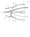
図2は、本発明の第1の実施形態の切替バルブ構造40の断面図である。
FIG. 2 is a cross-sectional view of the switching
切替バルブ構造40は、第1の排気管41と、第2の排気管42と、第3の排気管43とが互いに接合されて構成される。
The switching
なお、これら三つの排気管は、図1における上流側管22が第1の排気管41に、図1における分岐管23が第2の排気管42に、図1におけるバイパス管26が第3の排気管43に、それぞれ対応する。
In these three exhaust pipes, the
第1の排気管41の端部は、その外径が、端部に向かうにつれて徐々に拡径された拡大部411が構成されている。
The end portion of the
また、第2の排気管42は、端部へと向かうにつれて徐々に縮径すると共に、その端部の一部がガス流れ方向に平坦に加工された平坦部422を備える差込部421が構成されている。
In addition, the
同様に第3の排気管43も、端部へと向かうにつれて徐々に縮径すると共に、その端部の一部がガス流れ方向に平坦に加工された平坦部432を備える差込部431が構成されている。
Similarly, the diameter of the
これら差込部421及び431の端部の断面は、半月状(アルファベットの“D”形状)となっている。この差込部421及び431を、平坦部422及び432で互いに向かい合わせて接触させた状態で、第2の排気管42及び第3の排気管43を、第1の排気管の拡大部411に挿嵌されている。
The cross sections of the end portions of the
そして、これらを第1の排気管41、第2の排気管42及び第3の排気管43を、溶接等によって接合することによって、切替バルブ構造40が構成される。なお、平坦部422及び432で互いに接触させた差込部421及び431の外周の形状は、拡大部411の内周の形状と略同一に形成されていることは言うまでもない。
And the switching
これにより、切替バルブ構造40が構成される。
Thereby, the switching
なお、第2の排気管42の平坦部422と、第3の排気管43の平坦部432とは、拡大部411への差し込み深さが異なる。
The
具体的には、図2に示すように、第3の排気管43の差込部431が、第2の排気管42の差込部421よりも、拡大部411の奥側へと挿入されている。これにより、平坦部432の端部が、平坦部422の端部よりも、拡大部411の奥側へと延設されている。
Specifically, as shown in FIG. 2, the
これにより、第3の排気管43の差込部431の平坦部432の外周側の一部が、切替バルブ構造40の内部に露出するように構成されている。
Accordingly, a part of the outer peripheral side of the
第1の排気管41の拡大部411の内部には、第2の排気管42及び第3の排気管43のいずれか一方への排ガスの流れを規制するためのバルブ50が備えられる。バルブ50は、軸51によって回転可能に軸支される。
Inside the
なお、バルブ50は、図示しないモータやソレノイド等のアクチュエータによって軸51を回転駆動することにより回動される。
The
図2に示す例では、バルブ50が、第3の排気管43の差込部431の下方側の端部に接触している状態を示す。この状態では、第3の排気管43側を閉成して、第2の排気管42側へと排ガスを流通させることができる。この状態での排ガスの流れが、図中太線矢印で示されている。
In the example illustrated in FIG. 2, the
また、バルブ50を、点線で示すように、第2の排気管42の差込部421の上方側の端部に接触させた場合は、第2の排気管42側を閉成して、第3の排気管43側へと排ガスを流通させることができる。この状態での排ガスの流れが、図中点線矢印で示されている。
Further, when the
このような構造により、切替バルブ構造40は、第1の排気管41から流入する排ガスを、他の二つの排気管(第2の排気管42、第3の排気管43)のうち、少なくとも一方への排ガスの流れを制限して、他方へと流通させるように切り替えることができる。
With such a structure, the switching
軸51は、切替バルブ構造40内部の平坦部432の端部よりも、排気ガス流れ上流方向に備えられる。そのため、バルブ50によって、一方の排気管を閉成した場合にも、若干の隙間が生じ、閉成側の排気管に若干の排ガスの漏れを生じる。
The
例えば、熱交換を行うためにバイパス管26側を閉成し、分岐管23側を開成した場合にも、バイパス管26側へと若干の排ガスの漏れが生じる。
For example, even when the
しかしながら、熱交換を行う場合は、通常、エンジン10の出力が高い場合であり、排ガスの量及び温度も十分な状態である場合がほとんどである。従って、エンジン10から排出された全ての排ガスを熱交換機へと流通させないとしても、熱効率の低下は僅かであり、影響は小さい。
However, when heat exchange is performed, the output of the
また一方で、熱交換を停止するために行うために分岐管23側を閉成し、バイパス管26側を開成した場合には、排熱回収器24が介在する分岐管23は、バイパス管26よりも通気抵抗が高いため、若干の隙間があったとしても、排ガスは分岐管23側へはほとんど流れないため、影響は少ない。
On the other hand, when the
このように構成された切替バルブ構造40は、上流側、すなわち第1の排気管41から流入する排ガスを、バルブ50の開閉状態によって、第2の排気管42及び第3の排気管43の少なくとも一方への通過を規制することができる。
The switching
例えば、排ガスを排熱回収器24に流通させる場合(排熱回収時)には、バルブ50によって第3の排気管43側を閉成して、第1の排気管41から第2の排気管42(分岐管23)にのみ排ガスを流通させるように制御する。
For example, when exhaust gas is circulated through the exhaust heat recovery device 24 (at the time of exhaust heat recovery), the
また、媒体温度の状況等により排ガスを排熱回収器24に流通させない場合(非回収時)には、バルブ50によって第2の排気管42を閉成して、第1の排気管41から第3の排気管43(バイパス管26)にのみ排ガスを流通させるように制御する。
Further, when the exhaust gas is not circulated to the exhaust
またさらに、バルブ50の開度を制御して、第2の排気管42及び第3の排気管43に、排ガスを所定の割合で分配して流通させることもできる。
Further, the opening degree of the
以上説明したように、本発明の第1の実施形態の切替バルブ構造40は、上流側の第1の排気管41からの排ガスを、第2の排気管42及び第3の排気管43の少なくとも一方への通過を規制するバルブ50を備えた。
As described above, the switching
また、切替バルブ構造40は、第1の排気管41の端部を拡大した拡大部411に、第2の排気管42及び第3の排気管43の端部をそれぞれ加工した差込部421及び431を差し込んだ構造となっている。また、バルブ50は、拡大部411の内部に備えた。
In addition, the switching
このような構造により、切替バルブ構造40を構成する部品を削減することができる。これによりバルブ50を備えるための継手部分が必要なくなり、プレスによる鍛造品やロストワックスによる鋳物品等を別部品として形成する必要がなく、製造コストを抑えることができる。
With such a structure, the parts constituting the switching
特に、第1の排気管41の拡大部411の加工、第2の排気管42及び第3の排気管43の差込部421及び431の加工は、従来一般的に行われている管の加工方法により行うことができるので,加工コストを抑えることができる。
In particular, the processing of the
また、差込部421又は431の端部がバルブ50に接触することでバルブ50の開閉のストッパーにするので、排ガス通路内にバルブ50を受けるための別部品を設けることがないので、排ガスの抵抗となる物体が存在せず、排圧の悪化を抑制することができる。
In addition, since the end of the plug-in
また、差込部431の平坦部432を拡大部411側へと延設させることによって、バルブ50の軸51との距離を縮小できるので、バルブ50を閉成した側の排気管への排ガスの漏れを抑制することができる。
Further, by extending the
<第2実施形態>
次に、本発明の第2の実施形態について説明する。
Second Embodiment
Next, a second embodiment of the present invention will be described.
本発明の第2の実施形態の切替バルブ構造40は、前述の第1の実施形態とバルブ50の構造が異なる。なお、図1に示す第1の実施形態と基本構造は同一である。また、第1の実施形態と同一の構成には同一の符号を付して、その説明を省略する。
The switching
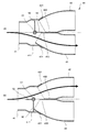
図3は、本発明の第2の実施形態の切替バルブ構造40の断面図である。なお、図3(a)は、バルブ50によって第2の排気管42を閉成した場合の断面図であり、図3(b)は、バルブ50によって第3の排気管43を閉成した場合の断面図である。
FIG. 3 is a sectional view of the switching
拡大部411の内部には、前述の第1の実施形態と同様にバルブ50が備えられる。また、軸51からバルブ50とは異なる側に突設されたストッパー52が備えられている。
Inside the
このストッパー52は、バルブ50と共に円弧状に回転するように軸51に軸支されている。また、ストッパー52が平坦部432へと当接することによって、バルブ50と共に第2の排気管42の開口部分を全て閉成する。
The
この平坦部432の平坦面には溶接等の加工がされていないので、組み立て後も平坦が保たれるので、ストッパー52が当接したときの排ガスの漏れを抑えることができる。
Since the flat surface of the
図3(a)に示すように、ストッパー55が、第3の排気管43の差込部431の平坦部432へと当接し、かつ、バルブ50が、拡大部411の内壁に当接している状態で、第2の排気管42側を完全に閉成して、第3の排気管43側のみに排ガスを流通させることができる。
As shown in FIG. 3A, the stopper 55 contacts the
また、図3(b)に示すように、バルブ50が、第3の排気管43の差込部431の下方側の端部に当接した場合は、第3の排気管43側を閉成して、第2の排気管42側へと排ガスを流通させることができる。なお、この状態では、ストッパー52は、いずれの構造にも接触していない。
Further, as shown in FIG. 3B, when the
このように構成することによって、本発明の第2の実施形態では、第1の実施形態の効果に加え、軸51からバルブ50とは異なる側に突設されたストッパー52によって第2の排気管42の開口部を全て閉成することができるので、排ガスを第2の排気管42側へと一切流さず、第3の排気管43にのみ流すことができる。
With this configuration, in the second embodiment of the present invention, in addition to the effects of the first embodiment, the second exhaust pipe is provided by the
特に、図1に示すように、第2の排気管42が排熱回収器24側へと接続されている場合は、エンジン10の運転状態によっては排ガスの熱交換を一切行わず、排ガスを全てバイパス管26へと流すよう制御したい場合がある。このときに、排ガスを全てバイパス管26に流すことにより、エンジン10への負荷が減るため燃費効率を高めるように制御することが可能となる。
In particular, as shown in FIG. 1, when the
なお、バイパス管26側を閉成し、熱交換状態とした場合には、バイパス管26へと若干の漏れが発生するが、前述の第1の実施形態と同様に、エンジン10から排出された全ての排ガスを分岐管23へと流通させないとしても、熱効率の低下は僅かであるので、影響は少ない。
In addition, when the
また、ストッパー52により排ガスの流れを完全に閉成する側を、分岐管23ではなく、バイパス管26側としてもよい。
Further, the side on which the exhaust gas flow is completely closed by the
<第3実施形態>
次に、本発明の第3の実施形態について説明する。
<Third Embodiment>
Next, a third embodiment of the present invention will be described.
本発明の第3の実施形態の切替バルブ構造40は、前述の第2の実施形態と類似しているが、バルブ50の構造がさらに異なる。なお、図1に示す第1の実施形態と基本構造は同一である。また、第1又は第2の実施形態と同一の構成には同一の符号を付して、その説明を省略する。
The switching
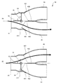
図4は、第3の実施形態の切替バルブ構造40の断面図である。
FIG. 4 is a cross-sectional view of the switching
拡大部411の内部には、前述の第1の実施形態のバルブ50と同様の第1のバルブ53が備えられる。また、軸51から第1のバルブ53とは異なる側に突設された第2のバルブ54が備えられている。
A
この第1のバルブ53と第2のバルブ54とは、互いに略直角となるように、その軸方向の断面が「L」字形状に構成される。また、第1のバルブ53と第2のバルブ54とは、その形状(軸51からの突き出し長、面積)が略同一に構成される。
The
第1のバルブ53は、第2の排気管42を閉成する。第2のバルブ54は、第3の排気管43を閉成する。
The
図4(a)に示すように、第1のバルブ53が、拡大部411の内壁に当接している状態で、第2の排気管42側を閉成して、第2の排気管42側への排ガスの流れを規制する。このとき、第2のバルブ54はいずれの構造にも接触していない。
As shown in FIG. 4A, the
また、図3(b)に示すように、これら第1のバルブ53及び第2のバルブ54を90度回転させて、第2のバルブ54が、第3の排気管43の差込部431の下方側の端部に当接した場合は、第3の排気管43側を閉成して、第3の排気管43側への排ガスの流れを規制する。このとき、この状態では、第1のバルブ53は、いずれの構造にも接触していない。
Further, as shown in FIG. 3B, the
このように、本発明の第3の実施形態では、第2の排気管42を閉成する第1のバルブ53と、第3の排気管43を閉成する第2のバルブ54と、を備えた。
As described above, the third embodiment of the present invention includes the
これらのバルブは軸51により回転可能に軸支されるが、その作動角度は、前述の第1又は第2の実施形態よりも小さい。
These valves are rotatably supported by a
これにより、第1の実施形態の効果に加え、バルブ50を回動させるための必要トルクが小さくなるので、より小型のアクチュエータを用いることができ、切替バルブ構造40のコストを抑えることができると共に、排気管の構成を小型化することができる。
Thereby, in addition to the effect of the first embodiment, the required torque for rotating the
なお、以上説明した本発明の第1から第3の実施形態では、エンジン10の排ガスを回収する排熱回収器24を備える分岐管23と、バイパス管26と、の分岐部30に用いる切替バルブ構造40を例に説明したが、これに限られるものではなく、合流部31に切替バルブ構造40を備えてもよい。この場合は、第1の排気管41が下流側管25に、第2の排気管42が分岐管23に、第3の排気管43がバイパス管26に、それぞれ相当する。
In the first to third embodiments of the present invention described above, the switching valve used for the
また、排ガスをエンジンに環流するEGRシステムにおいて、本実施形態の切替バルブ構造40を用いてもよい。これにより、EGRシステムを小型化することができると共に、製造コストの削減ができる。
Further, in the EGR system that circulates exhaust gas to the engine, the switching
10 エンジン(内燃機関)
20 排気管
22 上流側管
23 分岐管
24 排熱回収器
25 下流側管
30 分岐部
31 合流部
40 切替バルブ構造
41 第1の排気管
411 拡大部
42 第2の排気管
421 差込部
422 平坦部
43 第3の排気管
431 差込部
432 平坦部
50 バルブ
51 軸
52 ストッパー
53 第1のバルブ
54 第2のバルブ
10 Engine (Internal combustion engine)
DESCRIPTION OF SYMBOLS 20
Claims (3)
端部に向かうにつれて拡径された拡大部を有する第1の排気管と、
端部に向かうにつれて縮径されると共に、前記端部の一部に平坦部が形成された差込部を有する第2の排気管及び第3の排気管と、
前記拡大部に備えられた回転軸に支持され、前記第2の排気管又は第3の排気管への排ガスの流れを制限するバルブと、
を備え、
前記第2の排気管の平坦部と前記第3の排気管の平坦部とを向かい合わせた状態で、前記第2の排気管の差込部と前記第3の排気管の差込部とが前記拡大部へと挿嵌され、
前記第3の排気管の平坦部の端部が、前記第2の排気管の平坦部の端部よりも前記第1の排気管側へと延設されることを特徴とする切替バルブ構造。 A switching valve structure for branching an exhaust gas passage of an internal combustion engine,
A first exhaust pipe having an enlarged portion that is enlarged in diameter toward the end portion;
A second exhaust pipe and a third exhaust pipe that have an insertion portion in which the diameter is reduced toward the end portion and a flat portion is formed in a part of the end portion;
A valve that is supported by a rotary shaft provided in the enlarged portion and restricts the flow of exhaust gas to the second exhaust pipe or the third exhaust pipe;
With
With the flat part of the second exhaust pipe and the flat part of the third exhaust pipe facing each other, the insertion part of the second exhaust pipe and the insertion part of the third exhaust pipe are Inserted into the enlarged portion,
The switching valve structure characterized in that an end portion of the flat portion of the third exhaust pipe extends toward the first exhaust pipe side than an end portion of the flat portion of the second exhaust pipe.
前記回転軸から前記バルブと異なる方向へ突設される突設部を備え、前記第3の排気管の差込部の平坦部に前記突設部を当接することによって、前記第2の排気管への排ガスの流れを制限することを特徴とする切替バルブ構造。 In the switching valve structure according to claim 1,
The second exhaust pipe includes a projecting portion projecting from the rotating shaft in a direction different from that of the valve, and the projecting portion abuts against a flat portion of the insertion portion of the third exhaust pipe. Switching valve structure characterized by restricting the flow of exhaust gas to
前記バルブは、前記拡大部の内壁に当接することによって前記第2の排気管への排ガスの流れを制限する第1のバルブと、前記バルブの回転軸から前記バルブと異なる方向へ突設され、前記第3の排気管の差込部の平坦面に当接することによって前記第3の排気管への排ガスの流れを規制する第2のバルブと、を備えることを特徴とする切替バルブ構造。 In the switching valve structure according to claim 1 or 2,
The valve protrudes in a direction different from the valve from the first valve that restricts the flow of exhaust gas to the second exhaust pipe by contacting the inner wall of the enlarged portion, A switching valve structure comprising: a second valve that regulates a flow of exhaust gas to the third exhaust pipe by abutting against a flat surface of the insertion portion of the third exhaust pipe.
Priority Applications (1)
| Application Number | Priority Date | Filing Date | Title |
|---|---|---|---|
| JP2009268690A JP2011111963A (en) | 2009-11-26 | 2009-11-26 | Switching valve structure |
Applications Claiming Priority (1)
| Application Number | Priority Date | Filing Date | Title |
|---|---|---|---|
| JP2009268690A JP2011111963A (en) | 2009-11-26 | 2009-11-26 | Switching valve structure |
Publications (1)
| Publication Number | Publication Date |
|---|---|
| JP2011111963A true JP2011111963A (en) | 2011-06-09 |
Family
ID=44234488
Family Applications (1)
| Application Number | Title | Priority Date | Filing Date |
|---|---|---|---|
| JP2009268690A Pending JP2011111963A (en) | 2009-11-26 | 2009-11-26 | Switching valve structure |
Country Status (1)
| Country | Link |
|---|---|
| JP (1) | JP2011111963A (en) |
Cited By (2)
| Publication number | Priority date | Publication date | Assignee | Title |
|---|---|---|---|---|
| JP2015145663A (en) * | 2014-02-04 | 2015-08-13 | トヨタ自動車株式会社 | exhaust heat recovery control device |
| CN108487980A (en) * | 2018-05-29 | 2018-09-04 | 西华大学 | A kind of special purpose vehicle exhaust system |
Citations (2)
| Publication number | Priority date | Publication date | Assignee | Title |
|---|---|---|---|---|
| JPS63128224U (en) * | 1987-02-17 | 1988-08-22 | ||
| JP2004190693A (en) * | 2002-12-06 | 2004-07-08 | Aisan Ind Co Ltd | Flow passage switching valve |
-
2009
- 2009-11-26 JP JP2009268690A patent/JP2011111963A/en active Pending
Patent Citations (2)
| Publication number | Priority date | Publication date | Assignee | Title |
|---|---|---|---|---|
| JPS63128224U (en) * | 1987-02-17 | 1988-08-22 | ||
| JP2004190693A (en) * | 2002-12-06 | 2004-07-08 | Aisan Ind Co Ltd | Flow passage switching valve |
Cited By (3)
| Publication number | Priority date | Publication date | Assignee | Title |
|---|---|---|---|---|
| JP2015145663A (en) * | 2014-02-04 | 2015-08-13 | トヨタ自動車株式会社 | exhaust heat recovery control device |
| US9458751B2 (en) | 2014-02-04 | 2016-10-04 | Toyota Jidosha Kabushiki Kaisha | Exhaust heat recovery control device |
| CN108487980A (en) * | 2018-05-29 | 2018-09-04 | 西华大学 | A kind of special purpose vehicle exhaust system |
Similar Documents
| Publication | Publication Date | Title |
|---|---|---|
| JP5108462B2 (en) | Heat recovery equipment | |
| JP5018592B2 (en) | Waste heat recovery device | |
| CN101349515B (en) | Exhaust heat recovery apparatus | |
| JP5977944B2 (en) | Exhaust system for internal combustion engines | |
| KR20150121232A (en) | Heat recovery system and heat exchanger | |
| KR20130041243A (en) | Exhaust heat recovery system with bypass | |
| JP2011111963A (en) | Switching valve structure | |
| JP2009013838A (en) | Exhaust heat recovery device | |
| CN104254672A (en) | Steam generator for a rankine process | |
| KR101619532B1 (en) | An engine exhaust steam withdrawal apparatus of vehicle | |
| JP5707123B2 (en) | Heat exchange unit and manufacturing method thereof | |
| WO2016002711A1 (en) | Waste heat regeneration system | |
| JP2007107389A (en) | Egr valve device for engine | |
| JP2016109018A (en) | Exhaust heat recovery apparatus | |
| JP2007247638A (en) | Exhaust heat recovery device | |
| JP2010144566A (en) | Switching valve structure | |
| JP2015031250A (en) | Exhaust heat recovery device | |
| CN107869407A (en) | It is integrated with the exhaust thermal management module of exhaust gas recirculatioon, recuperation of heat and latent heat storage | |
| JP2010138780A (en) | Selector valve structure | |
| JP2007100665A (en) | Exhaust passage structure of internal combustion engine | |
| JP2007239595A (en) | Exhaust system heat exchanger layout | |
| CN214093084U (en) | Exhaust flow path switching valve structure | |
| JP2007024022A (en) | Exhaust emission control device | |
| JP6171699B2 (en) | Exhaust heat recovery unit | |
| JP2006083784A (en) | Engine exhaust heat utilization device |
Legal Events
| Date | Code | Title | Description |
|---|---|---|---|
| A621 | Written request for application examination |
Free format text: JAPANESE INTERMEDIATE CODE: A621 Effective date: 20120920 |
|
| A977 | Report on retrieval |
Free format text: JAPANESE INTERMEDIATE CODE: A971007 Effective date: 20130823 |
|
| A131 | Notification of reasons for refusal |
Free format text: JAPANESE INTERMEDIATE CODE: A131 Effective date: 20130827 |
|
| A02 | Decision of refusal |
Free format text: JAPANESE INTERMEDIATE CODE: A02 Effective date: 20140107 |