EP1426557A1 - Casing for turbo charger - Google Patents
Casing for turbo charger Download PDFInfo
- Publication number
- EP1426557A1 EP1426557A1 EP02026895A EP02026895A EP1426557A1 EP 1426557 A1 EP1426557 A1 EP 1426557A1 EP 02026895 A EP02026895 A EP 02026895A EP 02026895 A EP02026895 A EP 02026895A EP 1426557 A1 EP1426557 A1 EP 1426557A1
- Authority
- EP
- European Patent Office
- Prior art keywords
- housing
- sheet metal
- connection
- housing according
- connecting pipe
- Prior art date
- Legal status (The legal status is an assumption and is not a legal conclusion. Google has not performed a legal analysis and makes no representation as to the accuracy of the status listed.)
- Granted
Links
- 238000002485 combustion reaction Methods 0.000 claims abstract description 13
- 239000002184 metal Substances 0.000 claims description 55
- 229910052751 metal Inorganic materials 0.000 claims description 55
- 238000009413 insulation Methods 0.000 claims description 13
- 238000003466 welding Methods 0.000 claims description 4
- 239000004744 fabric Substances 0.000 claims description 3
- 239000004753 textile Substances 0.000 claims description 3
- 230000000295 complement effect Effects 0.000 claims description 2
- 239000000463 material Substances 0.000 claims description 2
- 229910000831 Steel Inorganic materials 0.000 abstract 2
- 239000010959 steel Substances 0.000 abstract 2
- 238000004519 manufacturing process Methods 0.000 description 7
- 230000003197 catalytic effect Effects 0.000 description 4
- 238000013461 design Methods 0.000 description 4
- 125000006850 spacer group Chemical group 0.000 description 4
- 238000012546 transfer Methods 0.000 description 3
- 239000003054 catalyst Substances 0.000 description 2
- 238000006073 displacement reaction Methods 0.000 description 2
- 239000000835 fiber Substances 0.000 description 2
- 238000005495 investment casting Methods 0.000 description 2
- 238000000034 method Methods 0.000 description 2
- 229910001018 Cast iron Inorganic materials 0.000 description 1
- BPQQTUXANYXVAA-UHFFFAOYSA-N Orthosilicate Chemical compound [O-][Si]([O-])([O-])[O-] BPQQTUXANYXVAA-UHFFFAOYSA-N 0.000 description 1
- 238000010521 absorption reaction Methods 0.000 description 1
- 230000009172 bursting Effects 0.000 description 1
- 239000000919 ceramic Substances 0.000 description 1
- 238000010276 construction Methods 0.000 description 1
- 230000000694 effects Effects 0.000 description 1
- 238000005516 engineering process Methods 0.000 description 1
- 238000002474 experimental method Methods 0.000 description 1
- 238000004880 explosion Methods 0.000 description 1
- 239000003365 glass fiber Substances 0.000 description 1
- 238000005338 heat storage Methods 0.000 description 1
- 238000003780 insertion Methods 0.000 description 1
- 230000037431 insertion Effects 0.000 description 1
- 238000002955 isolation Methods 0.000 description 1
- 238000000462 isostatic pressing Methods 0.000 description 1
- 238000003825 pressing Methods 0.000 description 1
- 230000005855 radiation Effects 0.000 description 1
- 230000007704 transition Effects 0.000 description 1
Images


Classifications
-
- F—MECHANICAL ENGINEERING; LIGHTING; HEATING; WEAPONS; BLASTING
- F02—COMBUSTION ENGINES; HOT-GAS OR COMBUSTION-PRODUCT ENGINE PLANTS
- F02B—INTERNAL-COMBUSTION PISTON ENGINES; COMBUSTION ENGINES IN GENERAL
- F02B67/00—Engines characterised by the arrangement of auxiliary apparatus not being otherwise provided for, e.g. the apparatus having different functions; Driving auxiliary apparatus from engines, not otherwise provided for
- F02B67/10—Engines characterised by the arrangement of auxiliary apparatus not being otherwise provided for, e.g. the apparatus having different functions; Driving auxiliary apparatus from engines, not otherwise provided for of charging or scavenging apparatus
-
- F—MECHANICAL ENGINEERING; LIGHTING; HEATING; WEAPONS; BLASTING
- F01—MACHINES OR ENGINES IN GENERAL; ENGINE PLANTS IN GENERAL; STEAM ENGINES
- F01D—NON-POSITIVE DISPLACEMENT MACHINES OR ENGINES, e.g. STEAM TURBINES
- F01D25/00—Component parts, details, or accessories, not provided for in, or of interest apart from, other groups
- F01D25/24—Casings; Casing parts, e.g. diaphragms, casing fastenings
- F01D25/26—Double casings; Measures against temperature strain in casings
-
- F—MECHANICAL ENGINEERING; LIGHTING; HEATING; WEAPONS; BLASTING
- F01—MACHINES OR ENGINES IN GENERAL; ENGINE PLANTS IN GENERAL; STEAM ENGINES
- F01D—NON-POSITIVE DISPLACEMENT MACHINES OR ENGINES, e.g. STEAM TURBINES
- F01D9/00—Stators
- F01D9/02—Nozzles; Nozzle boxes; Stator blades; Guide conduits, e.g. individual nozzles
- F01D9/026—Scrolls for radial machines or engines
-
- F—MECHANICAL ENGINEERING; LIGHTING; HEATING; WEAPONS; BLASTING
- F01—MACHINES OR ENGINES IN GENERAL; ENGINE PLANTS IN GENERAL; STEAM ENGINES
- F01N—GAS-FLOW SILENCERS OR EXHAUST APPARATUS FOR MACHINES OR ENGINES IN GENERAL; GAS-FLOW SILENCERS OR EXHAUST APPARATUS FOR INTERNAL COMBUSTION ENGINES
- F01N13/00—Exhaust or silencing apparatus characterised by constructional features ; Exhaust or silencing apparatus, or parts thereof, having pertinent characteristics not provided for in, or of interest apart from, groups F01N1/00 - F01N5/00, F01N9/00, F01N11/00
- F01N13/08—Other arrangements or adaptations of exhaust conduits
- F01N13/10—Other arrangements or adaptations of exhaust conduits of exhaust manifolds
- F01N13/102—Other arrangements or adaptations of exhaust conduits of exhaust manifolds having thermal insulation
-
- F—MECHANICAL ENGINEERING; LIGHTING; HEATING; WEAPONS; BLASTING
- F02—COMBUSTION ENGINES; HOT-GAS OR COMBUSTION-PRODUCT ENGINE PLANTS
- F02B—INTERNAL-COMBUSTION PISTON ENGINES; COMBUSTION ENGINES IN GENERAL
- F02B39/00—Component parts, details, or accessories relating to, driven charging or scavenging pumps, not provided for in groups F02B33/00 - F02B37/00
-
- F—MECHANICAL ENGINEERING; LIGHTING; HEATING; WEAPONS; BLASTING
- F02—COMBUSTION ENGINES; HOT-GAS OR COMBUSTION-PRODUCT ENGINE PLANTS
- F02C—GAS-TURBINE PLANTS; AIR INTAKES FOR JET-PROPULSION PLANTS; CONTROLLING FUEL SUPPLY IN AIR-BREATHING JET-PROPULSION PLANTS
- F02C6/00—Plural gas-turbine plants; Combinations of gas-turbine plants with other apparatus; Adaptations of gas-turbine plants for special use
- F02C6/04—Gas-turbine plants providing heated or pressurised working fluid for other apparatus, e.g. without mechanical power output
- F02C6/10—Gas-turbine plants providing heated or pressurised working fluid for other apparatus, e.g. without mechanical power output supplying working fluid to a user, e.g. a chemical process, which returns working fluid to a turbine of the plant
- F02C6/12—Turbochargers, i.e. plants for augmenting mechanical power output of internal-combustion piston engines by increase of charge pressure
-
- F—MECHANICAL ENGINEERING; LIGHTING; HEATING; WEAPONS; BLASTING
- F04—POSITIVE - DISPLACEMENT MACHINES FOR LIQUIDS; PUMPS FOR LIQUIDS OR ELASTIC FLUIDS
- F04D—NON-POSITIVE-DISPLACEMENT PUMPS
- F04D29/00—Details, component parts, or accessories
- F04D29/40—Casings; Connections of working fluid
- F04D29/42—Casings; Connections of working fluid for radial or helico-centrifugal pumps
- F04D29/4206—Casings; Connections of working fluid for radial or helico-centrifugal pumps especially adapted for elastic fluid pumps
-
- F—MECHANICAL ENGINEERING; LIGHTING; HEATING; WEAPONS; BLASTING
- F04—POSITIVE - DISPLACEMENT MACHINES FOR LIQUIDS; PUMPS FOR LIQUIDS OR ELASTIC FLUIDS
- F04D—NON-POSITIVE-DISPLACEMENT PUMPS
- F04D29/00—Details, component parts, or accessories
- F04D29/60—Mounting; Assembling; Disassembling
- F04D29/601—Mounting; Assembling; Disassembling specially adapted for elastic fluid pumps
-
- F—MECHANICAL ENGINEERING; LIGHTING; HEATING; WEAPONS; BLASTING
- F02—COMBUSTION ENGINES; HOT-GAS OR COMBUSTION-PRODUCT ENGINE PLANTS
- F02B—INTERNAL-COMBUSTION PISTON ENGINES; COMBUSTION ENGINES IN GENERAL
- F02B37/00—Engines characterised by provision of pumps driven at least for part of the time by exhaust
- F02B37/02—Gas passages between engine outlet and pump drive, e.g. reservoirs
-
- F—MECHANICAL ENGINEERING; LIGHTING; HEATING; WEAPONS; BLASTING
- F02—COMBUSTION ENGINES; HOT-GAS OR COMBUSTION-PRODUCT ENGINE PLANTS
- F02B—INTERNAL-COMBUSTION PISTON ENGINES; COMBUSTION ENGINES IN GENERAL
- F02B37/00—Engines characterised by provision of pumps driven at least for part of the time by exhaust
- F02B37/12—Control of the pumps
- F02B37/18—Control of the pumps by bypassing exhaust from the inlet to the outlet of turbine or to the atmosphere
-
- F—MECHANICAL ENGINEERING; LIGHTING; HEATING; WEAPONS; BLASTING
- F05—INDEXING SCHEMES RELATING TO ENGINES OR PUMPS IN VARIOUS SUBCLASSES OF CLASSES F01-F04
- F05D—INDEXING SCHEME FOR ASPECTS RELATING TO NON-POSITIVE-DISPLACEMENT MACHINES OR ENGINES, GAS-TURBINES OR JET-PROPULSION PLANTS
- F05D2220/00—Application
- F05D2220/40—Application in turbochargers
-
- Y—GENERAL TAGGING OF NEW TECHNOLOGICAL DEVELOPMENTS; GENERAL TAGGING OF CROSS-SECTIONAL TECHNOLOGIES SPANNING OVER SEVERAL SECTIONS OF THE IPC; TECHNICAL SUBJECTS COVERED BY FORMER USPC CROSS-REFERENCE ART COLLECTIONS [XRACs] AND DIGESTS
- Y10—TECHNICAL SUBJECTS COVERED BY FORMER USPC
- Y10T—TECHNICAL SUBJECTS COVERED BY FORMER US CLASSIFICATION
- Y10T428/00—Stock material or miscellaneous articles
- Y10T428/24—Structurally defined web or sheet [e.g., overall dimension, etc.]
- Y10T428/24628—Nonplanar uniform thickness material
Definitions
- the invention relates to a housing for turbochargers with a rotor space for receiving a turbine rotor, which rotor space is surrounded by a housing jacket, which is at least partially made of sheet metal. There is also a connection pipe for the Connection to at least one exhaust manifold of an internal combustion engine provided.
- Turbine housings made of sheet metal have been proposed variously. An example this is the case with US-A-2,801,043, DE-A-100 22 052 or WO 01/94754 remove.
- the advantage of such a solution is that it is easier to manufacture and lighter in weight than cast turbine housings.
- LSI technology d.s. Insulated air gap housing.
- a - apart from the manufacturing problems - a completely different problem with turbochargers, from which the present invention is based is the fact that after the Starting an internal combustion engine the catalytic converter takes a certain amount of time to reach operating temperature to come, where he unfolds his full performance. Is during this Time the turbocharger is in operation, it absorbs part of the exhaust gas heat, so that the gas reaching the catalytic converter has already cooled down somewhat, and thus the catalytic converter takes a long time to reach operating temperature. This time extended cast iron housings because there is a much greater heat absorption capacity.
- the invention is based on the knowledge that for the last problem addressed the use of a turbine housing made of sheet metal represents an improvement, but still not an optimum in thermal engineering Respect is achieved.
- the heat-conducting connection at least partially designed as a sliding connection, and preferably a funnel-shaped Widening of a tubular part, in particular the housing wall, in which the tubular end of the respective other part, in particular the connecting pipeline, is pluggable.
- sliding connection is to be understood as a connection in which the parts are inserted into one another are, but still the possibility of a pushing relative movement due to Thermal expansion, vibrations etc.
- the housing jacket consists of at least two sheet metal layers arranged one above the other exists, it is advantageous to make the outer one thicker than the inner one, because on the one hand is due to the at least double sheet layer a higher strength and still better insulation (less heat loss) achieved, on the other hand offers a thicker sheet layer, and that is advantageous the outer, a better burst protection.
- the inner, thinner sheet layer reach their maximum heat storage capacity relatively quickly, i.e. the thinner the inner wall, the faster this time is reached. There that amount of heat, which is then to the environment by radiation or convection is emitted, is essentially constant, the exhaust gas can no more heat be withdrawn.
- the inner sheet metal layer of the housing shell can be used at least one outer layer can be provided in the form of an insulation layer.
- Such Insulation layer can for example consist of a ceramic fleece or of silicate fibers consist. As experiments have shown, such a layer does more than just its job of insulation, but also improves burst protection.
- the insulation layer is made of a textile material (e.g. a glass fiber fabric, - knitted or crocheted) is formed.
- a textile material e.g. a glass fiber fabric, - knitted or crocheted
- Examples of such insulation can be found, for example from WO 97/48943 or WO 00/05532, the content of which can be found here Reference should be considered disclosed. In any case, the insulation layer does not bring only better thermal insulation, but also increases safety against bursting.
- the manufacture of a housing according to the invention is advantageously carried out so that the Housing shell composed of at least two complementary spiral parts which are connected to one another by welding, preferably also a supply gas channel of the housing jacket with the connecting pipeline over the length is made in two parts and each in one piece with the associated spiral part.
- a tight and reliable connection that is also less than space consuming is as with the previously used flanges. This can be done with a single weld the connection over the entire length (seen transversely to the axis of rotation of the turbine) become.
- the header pipe section 4 provides the connection between those formed from the parts 3 Exhaust collector and a turbine housing 17 ago.
- the manifold section 4 also ends the middle exhaust manifold 1 (but it could also be any other exhaust manifold, such as about one at the end of the exhaust manifold), while, as can be seen, in the axial direction is connected to a T exhaust pipe 3 each.
- At least part of this is advantageous Components of the exhaust manifold, preferably at least the collector pipe 4, at most also at least part of the T-exhaust pipes, made of deformed sheet metal, wherein Explosion deformation is conceivable as the deformation process, but preferably isostatic Pressing or hydraulic pressing (e.g. using hydraulic Pressure from the inside on a sheet in a corresponding shape).
- Another connection from the header pipe section 4 can go to a bypass duct 5, via the at least part of the exhaust gas of the internal combustion engine 20 via a by means of a lever 11 operated flap 10 (the arrow only shows the location of this flap an) can be fed to another user, such as the catalyst.
- the lever 11 is attached to a shaft mounted in a flange 9, to which Flange connects an outlet channel 8 or can be welded to it.
- a special socket as in the prior art for accommodating the flap at 10 and their actuation shaft with the lever 11 can be omitted.
- the turbine housing 17 is, as usual, approximately spiral-shaped, so as to remove the exhaust gas to a turbine located in the middle of the spiral (cf. 18 in FIGS. 3, 4). It surrounds in a conventional manner a rotor space 15 in which the turbine rotor 18 rotates (see Fig. 3, 4). As can be seen particularly from FIG. 1, the turbine housing settles 17 composed of a left spiral half 6 and a right spiral half 7, which Halves are welded together along the seam 19 visible in FIG. 1. Thereby a dense and less space-consuming unit is created than with a (also heavier) flange connection can be reached along the line 19 could. The bearing housing or the compressor housing can then be on the right housing half 7 of a turbocharger, which is driven by the turbine 18 becomes.
- a bearing housing flange 14 is used to connect these parts of a turbocharger provided that is welded to the right spiral half 7 or sealed in some other way can be connected.
- the left housing half 6, on the other hand, not only forms the half spiral, but also the known wheel contour of the turbine 18 (Fig. 3, 4) or the connection to an outlet channel 8, as is conventionally provided.
- This outlet duct 8 can preferably also consist of sheet metal and in a similar manner with the turbine housing 17 be connected, as will be explained later using the connection between Feed gas duct 21 and turbine housing 17 in connection with FIG. 3 or 4 is described.
- the weld seam 19 does not only extend over the spiral housing part of the turbine housing 17, but is extended so that it is in one piece also forms the feed gas duct 21 which is directly connected to the header pipe section 4, which reduces heat loss and makes production easier.
- a further sheet metal layer can be provided, like an end plate at 13 or at most a burst jacket. It is under the Invention quite possible, for example, to arrange four sheet metal layers one above the other. However, mixed forms are quite possible in which individual parts, such as the final part 13 or the bearing housing flange 14 discussed above are made of investment casting.
- Fig. 2 illustrates the structure described above and the associated parts in one exploded representation. 3 and in particular 4 should now be used with the help of Examples consisting of two sheet metal layers and at least one insulating layer be shown how these parts are assembled.
- the outside of the turbine housing 17 is made of the inner spiral part 6 made of sheet metal, for example from 0.5 to 1.5 mm, the outside of one stronger sheet metal jacket 22 is surrounded.
- the sheet metal jacket 22 has, for example a thickness in the range of 1.5 to 5 mm.
- the outer sheet metal jacket 22 can approximately may be 1.5 to 3 times as thick as the inner jacket 6. Between these Sheet metal layers is preferably a distance of at least 1 mm and preferably a maximum 8mm. For example, the distance is in the range of 2 to 5 mm.
- the outer sheet metal jacket can also be composed of two (spiral) halves be, of course, in any case, the production of more than two parts possible is.
- Both layers can be spaced apart by appropriately insulating spacers 23 are held apart, the spacer 23 shown in Fig. 3, the outlet channel 21 of the turbine housing 17 can surround a ring. in the one shown on the right in FIG. 3 End region of the sheet metal jacket 22 is pressed against the inner sheet (part 6) and welded to it, for example.
- At least one insulating layer can be provided between the two sheet metal layers 6, 22 become.
- a thin metal or sheet metal layer 26 may also be arranged between them can be, for example, reflective towards the radial interior is.
- the sheet metal layer 26 shown in FIG. 3 is only in the area of the feed channel 21 is provided, but can be in the entire space between the inner sheet metal layer 6 and the sheet metal jacket 22 can be provided. This is particularly advantageous if such an inner sheet metal layer 26 in the area of the volute around the turbine space is arranged because this ensures an even better burst protection.
- a branch 4 'of the header piece 4 (see FIG. 2) without welding with a mere plug connection connected, which forms a connecting pipeline.
- this connecting pipe 4 ' but possibly also the whole Collecting pipe piece 4, from an inner tube 27, an insulating layer 28 and a sheet metal jacket 29 is constructed.
- this sheet metal jacket 29 can also be made of something thicker Sheet metal exist, although no burst protection is required in this area.
- the one-piece design of the connecting pipeline 4 'with the header piece 4 is preferred, but within the scope of the present invention is not absolutely necessary.
- This nose piece 30 Between the inner sheet 27 and the sheet metal jacket 29 is an annular nose piece 30 clamped or welded to the sheet metal jacket 29.
- the left end (related to Fig. 3) of this nose piece 30 can be welded to the inner plate 27. But it is it is also possible to provide only one welding point, since this will suffice for one to avoid mutual displacement of the parts.
- This nose piece works with one conical expansion 32 at the end of the feed gas channel 21 together by putting it together with the expansion to support a snapped or by means of a (Not shown) screw contracted open clamping ring 31 is used secures the seat of the connecting pipe 4 'on the feed gas channel 21.
- FIG. 4 An even better heat transfer is obtained with an embodiment according to FIG. 4.
- This Embodiment differs from that of FIG. 3 in that the cone piece 32 'has a flatter angle ⁇ than in the previous embodiment.
- This Angle ⁇ should be a maximum of 30 °, preferably a maximum of 20 °, so that the inner Sheet 27 comes to rest frictionally and a heat transfer over a relatively large area.
- this angle ⁇ should not be too small, either Insertion of the inner tube sheet 27 should not be difficult, and should be at least 7 ° be.
- the cheapest version is advantageously such that the cone piece 32 'as Inlet funnel for the volute casing 17 is used and just widened so much that in an adjoining cylinder section 32 "the connecting pipeline 4 'under contact can be pushed onto the inner surface of the cylinder section 32 ′′ Tightness is achieved, and the length of the cylinder section 32 "becomes appropriate chosen so that the connecting pipe 4 'therein with thermal expansion and as a result of vibrations of the internal combustion engine can shift in it. It is understood that it would be theoretically possible, the confluence of the feed gas channel 21 without a cone transition to be designed so that the mentioned cylinder section 32 "on the connecting pipe 4 'comes to rest.
- FIG. 4 not only the connecting pipe 4 'of the header pipe 4 is shown, but the entire manifold section 4 in section.
- This has a central opening 33 for the connection of the neighboring parts 3 (see FIG. 1). Behind this opening 33 (in Fig. 4 right), the inner tube 27 narrows by an inner elbow tube inserted into it 34 to record, which is housed in an outer tube 35 and on the flange 2 (see Fig. 1) is welded.
- an outer one can do this too Sheet metal jacket 22 similar to FIG. 3 can be provided.
- this outer sheet metal jacket 22 is interrupted, is here preferably with the respective inner sheet metal parts 6, 27, 34 carried out a mere plug or slide connection, as explained above, which is easy to manufacture, whereas the sheet metal jacket 22 is welded over the entire length shown in FIG. 4, which of the outside is not a problem.
- the inner part 6, 27, 34 not gas-tight and there can be gas in the space between the inner and outer Sheet 22 get where it contributes to the insulation rather.
- too all other layers 24-26 which were described with reference to FIG. 3, also here Application.
- the sheet metal jacket 22 has over the largest part of the invention the connecting pipe 4 'combined housing 17 an approximately uniform distance from the inner sheet layer 6 or 33.
- This distance is about 1 mm and preferably amount to a maximum of 8mm, but will expediently be in the range of 2 to 5mm.
- a smaller one (see 32 ") or a larger distance (see at 21) may be advantageous.
Landscapes
- Engineering & Computer Science (AREA)
- Mechanical Engineering (AREA)
- General Engineering & Computer Science (AREA)
- Chemical & Material Sciences (AREA)
- Combustion & Propulsion (AREA)
- Chemical Kinetics & Catalysis (AREA)
- General Chemical & Material Sciences (AREA)
- Supercharger (AREA)
- Exhaust Silencers (AREA)
- Exhaust Gas After Treatment (AREA)
Abstract
Description
Die Erfindung bezieht sich auf ein Gehäuse für Turbolader mit einem Rotorraum zur Aufnahme eines Turbinenrotors, welcher Rotorraum von einem Gehäusemantel umgeben ist, der mindestens zum Teil aus Blech besteht. Ferner ist eine Anschlußrohrleitung für den Anschluß an mindestens eine Abgassammelleitung eines Verbrennungsmotors vorgesehen.The invention relates to a housing for turbochargers with a rotor space for receiving a turbine rotor, which rotor space is surrounded by a housing jacket, which is at least partially made of sheet metal. There is also a connection pipe for the Connection to at least one exhaust manifold of an internal combustion engine provided.
Turbinengehäuse aus Blech sind schon verschiedentlich vorgeschlagen worden. Ein Beispiel dafür ist etwa der US-A-2,801,043, der DE-A-100 22 052 oder der WO 01/94754 zu entnehmen. Der Vorteil einer solchen Lösung liegt in der einfacheren Herstellbarkeit und im geringeren Gewicht gegenüber gegossenen Turbinengehäusen. Zu erwähnen ist auch die sogenannte LSI-Technik, d.s. Gehäuse mit isoliertem Luftspalt.Turbine housings made of sheet metal have been proposed variously. An example this is the case with US-A-2,801,043, DE-A-100 22 052 or WO 01/94754 remove. The advantage of such a solution is that it is easier to manufacture and lighter in weight than cast turbine housings. It should also be mentioned the so-called LSI technology, d.s. Insulated air gap housing.
Ein - abgesehen von den Herstellungsproblemen - ganz anderes Problem bei Turboladern, von dem auch die vorliegende Erfindung ausgeht, ist die Tatsache, daß nach dem Start eines Verbrennungsmotors der Katalysator eine gewisse Zeit benötigt, um auf Betriebstemperatur zu kommen, bei der er seine volle Leistung entfaltet. Ist während dieser Zeit der Turbolader in Betrieb, so nimmt dieser einen Teil der Abgaswärme auf, so daß das zum Katalysator gelangende Gas bereits etwas abgekühlt ist und somit der Katalysator längere Zeit benötigt, um auf Betriebstemperatur zu gelangen. Diese Zeit verlängert sich bei Gußgehäusen noch, weil hier ja eine viel größere Wärmeaufnahmefähigkeit besteht.A - apart from the manufacturing problems - a completely different problem with turbochargers, from which the present invention is based is the fact that after the Starting an internal combustion engine the catalytic converter takes a certain amount of time to reach operating temperature to come, where he unfolds his full performance. Is during this Time the turbocharger is in operation, it absorbs part of the exhaust gas heat, so that the gas reaching the catalytic converter has already cooled down somewhat, and thus the catalytic converter takes a long time to reach operating temperature. This time extended cast iron housings because there is a much greater heat absorption capacity.
Der Erfindung liegt - in einem ersten Schritt - die Erkenntnis zugrunde, daß für das zuletzt angesprochene Problem die Verwendung eines Turbinengehäuses aus Blech zwar eine Verbesserung darstellt, daß aber damit noch immer kein Optimum in wärmetechnischer Hinsicht erzielt wird. Insofern ist es Aufgabe der Erfindung, ein Gehäuse so auszugestalten, daß die Wärmeverluste über den Weg bis zum Katalysator möglichst gering sind. In a first step, the invention is based on the knowledge that for the last problem addressed the use of a turbine housing made of sheet metal represents an improvement, but still not an optimum in thermal engineering Respect is achieved. In this respect, it is an object of the invention to design a housing that the heat losses over the way to the catalyst are as low as possible are.
Diese Aufgabe wird erfindungsgemäß dadurch gelöst, daß nicht nur der Gehäusemantel des Rotorraumes aus Blech besteht, sondern daß auch die Anschlußrohrleitung zur Verbindung mit der Abgassammelleitung aus Blech geformt ist und mit dem aus Blech bestehenden Gehäusemantel in wärmeleitender Verbindung steht. Damit wird ein im wesentlichen ungestörter Wärmefluß direkt von der Wärmequelle, d.h. dem Verbrennungsmotor, bis hinter den Turbolader sichergestellt, so daß ein nachgeschalteter Katalysator trotz gleichzeitigem Betrieb eines Turboladers relativ rasch seinen Betriebszustand erreicht. Mit einem Wort, die Wärmekapazität ist geringer als bei einem gegossenen Gehäuse + Anschlußrohrleitung.This object is achieved in that not only the housing jacket of the rotor space is made of sheet metal, but also that the connecting pipeline for connection is formed with the exhaust manifold from sheet metal and with the existing from sheet metal Housing jacket is in a thermally conductive connection. This essentially becomes a undisturbed heat flow directly from the heat source, i.e. the internal combustion engine, ensured behind the turbocharger, so that a downstream catalytic converter reached its operating state relatively quickly despite simultaneous operation of a turbocharger. In a word, the heat capacity is lower than that of a cast housing + Connecting pipe.
Es ist aber nicht nur die Lösung dieser Aufgabe, welche durch die Erfindung gelingt, sondern es ergeben sich in überraschender Weise auch noch weitere Vorteile:
- während beim oben zitierten Stand der Technik der Anschluß des Gehäuses an den Abgassammler über eine Flanschverbindung erfolgte, fällt dies nun weg, was seinerseits eine gewisse Gewichtsersparnis mit sich bringt;
- damit aber wird auch die Montage erleichtert, da der bisher benötigte Platzbedarf für die Befestigung der Flanschschrauben entfällt, d.h. aber auch, daß die Anordnung kompakter sein kann, wenn dies gewünscht wird;
- ebenso entfällt die Flanschdichtung;
- während beim Stand der Technik neben der Flanschverbindung noch eine große Anzahl von Schweißnähten erforderlich war, entfällt dies weitgehend bei der erfindungsgemäßen Ausbildung.
- whereas in the prior art cited above, the housing was connected to the exhaust manifold via a flange connection, this is no longer necessary, which in turn results in a certain weight saving;
- but this also makes assembly easier, since the space required hitherto for fastening the flange screws is eliminated, but also that the arrangement can be more compact if desired;
- the flange seal is also omitted;
- While the prior art required a large number of welds in addition to the flange connection, this is largely eliminated in the design according to the invention.
Eine weitere Vereinfachung ergibt sich, wenn die wärmeleitende Verbindung mindestens zum Teil als Schiebeverbindung ausgeführt ist, und vorzugsweise eine trichterförmige Aufweitung des einen rohrförmigen Teiles, insbesondere der Gehäusewand, aufweist, in die das rohrförmige Ende des jeweiligen anderen Teiles, insbesondere der Anschlußrohrleitung, steckbar ist. Damit entfallen aufwendige Montagevorgänge. Unter "Schiebeverbindung" ist dabei eine Verbindung zu verstehen, bei der die Teile ineinandergesteckt sind, aber noch immer die Möglichkeit einer schiebenden Relativbewegung auf Grund von Wärmedehnungen, Vibrationen etc. haben.A further simplification results if the heat-conducting connection at least partially designed as a sliding connection, and preferably a funnel-shaped Widening of a tubular part, in particular the housing wall, in which the tubular end of the respective other part, in particular the connecting pipeline, is pluggable. This eliminates the need for complex assembly processes. Under "sliding connection" is to be understood as a connection in which the parts are inserted into one another are, but still the possibility of a pushing relative movement due to Thermal expansion, vibrations etc.
Wenn der Gehäusemantel aus mindestens zwei übereinander angeordneten Blechlagen besteht, so ist es vorteilhaft, die äußere dicker auszuführen ist als die innere, denn einerseits wird durch die mindestens doppelte Blechlage eine höhere Festigkeit und eine noch bessere Isolation (weniger Wärmeverlust) erreicht, anderseits bietet eine dickere Blechlage, und die ist vorteilhaft die äußere, einen besseren Berstschutz. Dazu kommt, daß die innere, dünnere Blechlage so relativ rasch ihre maximale Wärmespeicherkapazität erreichen, d.h. je dünner die Innenwand ist, desto rascher ist dieser Zeitpunkt erreicht. Da diejenige Wärmemenge, welche dann an die Umgebung durch Strahlung bzw. Konvektion abgegeben wird, im wesentlichen konstant ist, kann dem Abgas keine weitere Wärme entzogen werden.If the housing jacket consists of at least two sheet metal layers arranged one above the other exists, it is advantageous to make the outer one thicker than the inner one, because on the one hand is due to the at least double sheet layer a higher strength and still better insulation (less heat loss) achieved, on the other hand offers a thicker sheet layer, and that is advantageous the outer, a better burst protection. In addition, the inner, thinner sheet layer reach their maximum heat storage capacity relatively quickly, i.e. the thinner the inner wall, the faster this time is reached. There that amount of heat, which is then to the environment by radiation or convection is emitted, is essentially constant, the exhaust gas can no more heat be withdrawn.
Diese letzteren Merkmale können nun so kombiniert werden, daß von den übereinander angeordneten Blechlagen die bzw. eine der inneren Lagen die Steck- oder Schiebeverbindung bildet, wogegen die jeweils äußerste Lage der Teile miteinander verschweißt sind. Denn damit wird eine nach außen hin dichte Verbindung geschaffen, ohne daß die inneren Schichten miteinander verschweißt werden müssen, wobei das Gas allenfalls dazwischen gelangen kann und zur Isolation beiträgt.These latter features can now be combined so that the one above the other arranged sheet metal layers or one of the inner layers the plug or slide connection forms, whereas the outermost layer of the parts is welded together are. Because this creates a tight connection to the outside without the inner layers must be welded together, the gas at most can get in between and contribute to isolation.
Zusätzlich oder alternativ kann über der innen liegenden Blechlage des Gehäusemantels mindestens eine äußere Lage in Form einer Isolationsschicht vorgesehen sein. Eine solche Isolationsschicht kann beispielsweise aus einem Keramikvlies oder aus Silikatfasern bestehen. Wie Versuche gezeigt haben, erfüllt eine solche Schicht nicht nur ihre Aufgabe der Isolation, sondern verbessert auch den Berstschutz.Additionally or alternatively, the inner sheet metal layer of the housing shell can be used at least one outer layer can be provided in the form of an insulation layer. Such Insulation layer can for example consist of a ceramic fleece or of silicate fibers consist. As experiments have shown, such a layer does more than just its job of insulation, but also improves burst protection.
Es hat sich allerdings gezeigt, daß derlei Isolationsschichten, wenn sie aus ungesponnenen Fasern bestehen, leicht dazu neigen, durch die Vibrationen des Verbrennungsmotors aus ihrer vorbestimmten Lage zu geraten und an einer Stelle ansammeln, wodurch natürlich die erwünschte Isolationswirkung nicht mehr voll gegeben ist. Deshalb ist es bevorzugt, wenn die Isolationsschicht aus einem Textilstoff (z.B. einem Glasfasergewebe, - gestricke oder -gewirke) gebildet ist. Beispiele solcher Isolierungen lassen sich beispielsweise der WO 97/48943 oder der WO 00/05532 entnehmen, deren Inhalt hier durch Bezugnahme als geoffenbart gelten soll. In jedem Falle bringt die Isolationsschicht nicht nur eine bessere Wärmedämmung, sondern erhöht auch die Berstsicherheit.However, it has been shown that such insulation layers, if they are made of non-spun Fibers are made to tend easily due to the vibrations of the internal combustion engine get out of their predetermined position and accumulate in one place, which of course the desired insulation effect is no longer fully available. Therefore it is preferred if the insulation layer is made of a textile material (e.g. a glass fiber fabric, - knitted or crocheted) is formed. Examples of such insulation can be found, for example from WO 97/48943 or WO 00/05532, the content of which can be found here Reference should be considered disclosed. In any case, the insulation layer does not bring only better thermal insulation, but also increases safety against bursting.
Die Herstellung eines erfindungsgemäßen Gehäuses erfolgt zweckmäßig so, daß der Gehäusemantel aus mindestens zwei, einander ergänzenden Spiralteilen zusammengesetzt ist, welche durch Schweißen miteinander verbunden sind, wobei vorzugsweise auch ein Zufuhrgaskanal des Gehäusemantels mit der Anschlußrohrleitung über die Länge zweiteilig und jeweils in einem Stück mit dem zugehörigen Spiralteil ausgeführt ist. Damit erhält man eine dichte und zuverlässige Verbindung, die auch weniger als platzaufwendig ist als mit den bisher benützten Flanschen. Damit kann mit einer einzigen Schweißnaht die Verbindung über die ganze Länge (gesehen quer zur Drehachse der Turbine) durchgeführt werden.The manufacture of a housing according to the invention is advantageously carried out so that the Housing shell composed of at least two complementary spiral parts which are connected to one another by welding, preferably also a supply gas channel of the housing jacket with the connecting pipeline over the length is made in two parts and each in one piece with the associated spiral part. In order to you get a tight and reliable connection that is also less than space consuming is as with the previously used flanges. This can be done with a single weld the connection over the entire length (seen transversely to the axis of rotation of the turbine) become.
Weitere Einzelheiten der Erfindung ergeben sich an Hand der nachfolgenden Beschreibung von in der Zeichnung schematisch dargestellten Ausführungsbeispielen. Es zeigen:
- Fig. 1
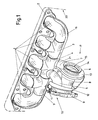
- eine Perspektivansicht einer erfindungsgemäß ausgeführten Einheit aus Abgassammler eines Verbrennungsmotors und einem Turbinengehäuse eines Turboladers;
- Fig. 2
- die einzelnen Teile dieser Einheit in explodierter Darstellung;
- Fig. 3
- ein erstes Ausführungsbeispiel der Verbindung von Turbinengehäuse und Anschlußrohr aus dem Abgassammler in einem Schnitt quer zur Achse der Turbine, wozu
- Fig. 4
- eine bevorzugte Alternative veranschaulicht.
- Fig. 1
- a perspective view of a unit designed according to the invention from the exhaust manifold of an internal combustion engine and a turbine housing of a turbocharger;
- Fig. 2
- the individual parts of this unit in an exploded view;
- Fig. 3
- a first embodiment of the connection of the turbine housing and connecting pipe from the exhaust manifold in a section transverse to the axis of the turbine, for what
- Fig. 4
- illustrates a preferred alternative.
Aus einem in Fig. 1 lediglich strich-punktiert angedeuteten Verbrennungsmotor 20 führen
fünf Abgaskrümmer 1 jeweils zu einzelnen T-Abgasrohren 3, die insgesamt einen Abgassammler
bilden und letztlich in ein Sammelrohrstück 4 münden. Es ist klar, daß dies nur
ein Beispiel darstellt und die Erfindung nicht auf eine bestimmte Anzahl von Abgaskrümmern
1 beschränkt ist. Die T-Abgasrohre 3 sind mit einem Eingangsflansch 2 verschweißt,
der am Verbrennungsmotor 20 befestigt ist. Die Erfindung ist jedoch auf diese
Ausführung nicht beschränkt, vielmehr kann auch ein Abgassammler an sich bekannter
Art verwendet werden, in den das Sammelrohrstück 4 eingesetzt ist. Im vorliegenden
Falle ist es vorteilhaft, die einzelnen Teile 3, 4 noch von unten durch einen unteren Deckel
16 abzudecken, dem ein hier nicht gezeigter oberer Deckel gegenüberliegen kann.
Zwischen den einzelnen Sammlerabschnitten 3, 4 und den Deckeln kann eine Isolierschicht,
z.B. aus einem Vlies, angeordnet sein.Lead out of an
Das Sammelrohrstück 4 stellt die Verbindung zwischen den aus den Teilen 3 gebildeten
Abgassammler und einem Turbinengehäuse 17 her. Im Sammelrohrstück 4 endet auch
der mittlere Abgaskrümmer 1 (es könnte aber auch jeder andere Abgaskrümmer, wie
etwa einer am Ende des Abgassammlers sein), während er, wie ersichtlich, in Axialrichtung
an je ein T-Abgasrohr 3 angeschlossen ist. Vorteilhaft ist wenigstens ein Teil dieser
Bestandteile des Abgassammlers, bevorzugt wenigstens das Sammlerohrstück 4, allenfalls
auch mindestens ein Teil der T-Abgasrohre, aus verformten Blech hergestellt, wobei
als Verformungsvorgang eine Explosionsverformung denkbar ist, bevorzugt jedoch isostatisches
Pressen bzw. hydraulisches Pressen (z.B. unter Anwendung von hydraulischem
Druck von innen auf ein in einer entsprechenden Form gelegenes Blech). Eine
Alternative könnte allerdings darin bestehen, das Sammelrohrstück 4 selbst aus einem
Feingußteil herzustellen.The
Eine weitere Verbindung aus dem Sammelrohrstück 4 kann zu einem Bypasskanal 5 gehen,
über den wenigstens ein Teil des Abgases des Verbrennungsmotors 20 über eine
mittels eines Hebels 11 betätigbaren Klappe 10 (der Pfeil zeigt nur den Ort dieser Klappe
an) einem weiteren Verwender, wie etwa dem Katalysator, zuführbar ist. Dabei ist ersichtlich,
daß der Hebel 11 an einer in einem Flansch 9 gelagerten Welle befestigt ist, an welchen
Flansch ein Auslaßkanal 8 anschließt bzw. mit ihm verschweißt sein kann. Eine
spezielle Buchse wie beim Stand der Technik für die Unterbringung der Klappe bei 10
sowie ihre Betätigungswelle mit dem Hebel 11 kann entfallen.Another connection from the
Das Turbinengehäuse 17 ist, wie üblich, etwa spiralförmig ausgebildet, um so das Abgas
einer in der Mitte der Spirale gelegenen Turbine (vgl. 18 in den Fig. 3, 4) zuzuführen. Es
umgibt in üblicher Weise einen Rotorraum 15, in welchem sich der Turbinenrotor 18 dreht
(vgl. Fig. 3, 4). Wie besonders aus Fig. 1 ersichtlich ist, setzt sich das Turbinengehäuse
17 aus einer linken Spiralhälfte 6 und einer rechten Spiralhälfte 7 zusammen, welche
Hälften miteinander entlang der in Fig. 1 sichtbaren Naht 19 verschweißt sind. Dadurch
wird eine dichte und weniger platzaufwendige Einheit geschaffen, als dies mit einer (auch
gewichtsmäßig schwereren) Flanschverbindung entlang der Linie 19 erreicht werden
könnte. An die rechte Gehäusehälfte 7 kann dann das Lagergehäuse bzw. das Kompressorgehäuse
eines Turboladers angeschlossen werden, der von der Turbine 18 angetrieben
wird. Zum Anschluß dieser Teile eines Turboladers ist ein Lagergehäuseflansch 14
vorgesehen, der mit der rechten Spiralhälfte 7 verschweißt ist oder auf andere Art dicht
verbunden sein kann. Die linke Gehäusehälfte 6 dagegen bildet nicht nur die halbe Spirale,
sondern auch die an sich bekannte Radkontur der Turbine 18 (Fig. 3, 4) bzw. den Anschluß
zu einem Auslaßkanal 8, wie er herkömmlich vorgesehen ist. Dieser Auslaßkanal
8 kann vorzugsweise ebenfalls aus Blech bestehen und auf ähnliche Weise mit dem Turbinengehäuse
17 verbunden sein, wie dies später noch an Hand der Verbindung zwischen
Zufuhrgaskanal 21 und Turbinengehäuse 17 im Zusammenhang mit den Fig. 3
oder 4 beschrieben wird.The
Denn, wie ersichtlich, erstreckt sich die Schweißnaht 19 nicht nur über den spiraligen Gehäuseteil
des Turbinengehäuses 17, sondern ist so verlängert, daß sie in einem Stück
auch den mit dem Sammelrohrstück 4 unmittelbar verbundenen Zufuhrgaskanal 21 bildet,
wodurch die Wärmeverluste verringert und die Herstellung erleichtert wird. Über dem so
hergestellten Turbinengehäuse kann noch eine weitere Blechlage vorgesehen werden,
wie ein Abschlußblech bei 13 bzw. allenfalls noch ein Berstmantel. Es ist im Rahmen der
Erfindung durchaus möglich, beispielsweise vier Blechlagen übereinander anzuordnen.
Allerdings sind Mischformen durchaus möglich, bei denen Einzelteile, wie der Abschlußteil
13 oder der oben besprochene Lagergehäuseflansch 14 aus Feinguß ausgeführt sind.Because, as can be seen, the
Fig. 2 verdeutlicht den oben beschriebenen Aufbau bzw. die dazu gehörigen Teile in einer explodierten Darstellung. An Hand der Fig. 3 und insbesondere 4 soll nun an Hand von aus zwei Blechlagen und mindestens einer Isolierschicht bestehenden Ausführungsbeispielen gezeigt werden, wie diese Teile zusammengefügt sind.Fig. 2 illustrates the structure described above and the associated parts in one exploded representation. 3 and in particular 4 should now be used with the help of Examples consisting of two sheet metal layers and at least one insulating layer be shown how these parts are assembled.
Gemäß Fig. 3 ist die Außenseite des Turbinengehäuses 17 aus dem inneren Spiralteil 6
aus Blech, beispielsweise von 0,5 bis 1,5 mm, aufgebaut, der an der Außenseite von einem
stärkeren Blechmantel 22 umgeben ist. Der Blechmantel 22 besitzt beispielsweise
eine Stärke im Bereiche von 1,5 bis 5 mm. Annähernd kann der äußere Blechmantel 22
gegebenenfalls 1,5 bis 3 mal so dick wie der innere Mantel 6 sein. Zwischen diesen
Blechlagen liegt vorzugsweise ein Abstand von mindestens 1 mm und vorzugsweise maximal
8mm. Beispielsweise liegt der Abstand im Bereiche von 2 bis 5mm. Wie die Spiralteile
6, 7 kann auch der äußere Blechmantel aus zwei (Spiral-)Hälften zusammengesetzt
sein, wobei natürlich in jedem Falle auch die Fertigung aus mehr als zwei Teilen möglich
ist.3, the outside of the
Beide Lagen können durch, zweckmäßig isolierende, Abstandhalter 23 in einem Abstand
voneinander gehalten werden, wobei der in Fig. 3 gezeigte Abstandhalter 23 den Auslaßkanal
21 des Turbinengehäuses 17 ringförmig umgeben kann. in dem in Fig. 3 rechts gezeigten
Endbereich des Blechmantels 22 ist derselbe gegen das Innenblech (Teil 6) gedrückt
und an dieses beispielsweise angeschweißt. Both layers can be spaced apart by appropriately insulating
Zwischen den beiden Blechlagen 6, 22 kann mindestens eine Isolierschicht vorgesehen
werden. Im gezeigten Ausführungsbeispiel sind es zwei Textilstoffschichten 24 bzw. 25,
zwischen denen gegebenenfalls auch noch eine dünne Metall- oder Blechschicht 26 angeordnet
sein kann, die beispielsweise gegen das radiale Innere hin reflektierend ausgebildet
ist. Die in Fig. 3 gezeigte Blechschicht 26 ist nur im Bereiche des Zufuhrkanales
21 vorgesehen, kann aber im gesamten Zwischenraum zwischen der inneren Blechlage 6
und dem Blechmantel 22 vorgesehen werden. Dies hat insbesondere einen Vorteil, wenn
eine solche innere Blechlage 26 im Bereiche des Spiralgehäuses rund um den Turbinenraum
angeordnet wird, weil dadurch ein noch besserer Berstschutz gewährleistet ist.At least one insulating layer can be provided between the two
An den zusammen mit dem Gehäuse 17 aus einem Stück hergestellten Zufuhrkanal 21
ist ein Ast 4' des Sammelrohrstückes 4 (vgl. Fig. 2) ohne Schweißung mit bloßer Steckverbindung
angeschlossen, der eine Anschlußrohrleitung bildet. Es ist ersichtlich, daß
auch mindestens diese Anschlußrohrleitung 4', gegebenenfalls aber auch das gesamte
Sammelrohrstück 4, aus einem inneren Rohr 27, einer Isolierlage 28 und einem Blechmantel
29 aufgebaut ist. Wie ersichtlich, kann auch dieser Blechmantel 29 aus etwas dickerem
Blech bestehen, obwohl ja in diesem Bereich kein Berstschutz erforderlich ist.
Hier sei aber angemerkt, daß die einteilige Ausführung der Anschlußrohrleitung 4' mit
dem Sammelrohrstück 4 zwar bevorzugt, aber im Rahmen der vorliegenden Erfindung
nicht unbedingt erforderlich ist.On the
Zwischen dem Innenblech 27 und dem Blechmantel 29 ist ein ringförmiges Nasenstück
30 eingeklemmt bzw. am Blechmantel 29 angeschweißt. Das linke Ende (bezogen auf
Fig. 3) dieses Nasenstückes 30 kann am Innenblech 27 angeschweißt sein. Es ist aber
ebenso möglich, nur eine Schweißstelle vorzusehen, da diese genügen wird, um eine
gegenseitige Verschiebung der Teile zu vermeiden. Dieses Nasenstück wirkt mit einer
konischen Aufweitung 32 am Ende des Zufuhrgaskanales 21 zusammen, indem es zusammen
mit der Aufweitung zur Abstützung eines aufgeschnappten oder mittels einer
(nicht dargestellten) Schraube zusammengezogenen offenen Klemmringes 31 dient, der
den Sitz der Anschlußrohrleitung 4' am Zufuhrgaskanal 21 sichert. Der Wärmeübergang
von der Anschlußrohrleitung 4' des Sammelrohrstückes auf das Turbinengehäuse 17 erfolgt
so über die Bleche 27, 29, das Nasenstück 30 und das Konusstück 32.Between the
Einen noch besseren Wärmeübergang erhält man bei einer Ausführung nach Fig. 4. Dieses
Ausführungsbeispiel unterscheidet sich von dem nach Fig. 3 dadurch, daß das Konusstück
32' einen flacheren Winkel α hat als bei der vorherigen Ausführungsform. Dieser
Winkel α sollte maximal 30°, vorzugsweise maximal 20° betragen, so daß das innere
Blech 27 reibungsschlüssig daran zu liegen kommt und ein Wärmeübergang über eine
relativ große Fläche erfolgt. Zu klein sollte dieser Winkel α aber auch nicht sein, um das
Einführen des inneren Rohrbleches 27 nicht zu erschweren, und sollte wenigstens 7°
betragen. Die günstigste Ausführung erfolgt vorteilhaft so, daß das Konusstück 32' als
Einlaßtrichter für das Spiralgehäuse 17 dient und gerade so sehr aufgeweitet ist, daß in
einem daran anschließenden Zylinderabschnitt 32" die Anschlußrohrleitung 4' unter Anlage
an die Innenfläche des Zylinderabschnittes 32" einschiebbar ist. Dabei wird eine weitgehende
Dichtheit erreicht, und die Länge des Zylinderabschnittes 32" wird zweckmäßig
so gewählt, daß sich die Anschlußrohrleitung 4' darin bei Wärmedehnungen und infolge
von Vibrationen des Verbrennungsmotors darin verschieben kann. Es versteht sich, daß
es theoretisch möglich wäre, die Einmündung des Zufuhrgaskanales 21 ohne Konusübergang
so zu gestalten, daß der erwähnte Zylinderabschnitt 32" an der Anschlußrohrleitung
4' zu liegen kommt.An even better heat transfer is obtained with an embodiment according to FIG. 4. This
Embodiment differs from that of FIG. 3 in that the cone piece
32 'has a flatter angle α than in the previous embodiment. This
Angle α should be a maximum of 30 °, preferably a maximum of 20 °, so that the
In Fig. 4 ist nicht nur die Anschlußrohrleitung 4' des Sammelrohrstückes 4 gezeigt, sondern
das ganze Sammelrohrstück 4 im Schnitt. Dieses weist eine mittlere Öffnung 33 für
den Anschluß der Nachbarteile 3 (vgl. Fig. 1) auf. Hinter dieser Öffnung 33 (in Fig. 4
rechts) verengt sich das Innenrohr 27, um ein in es hineingestecktes inneres Krümmerrohr
34 aufzunehmen, das in einem Außenrohr 35 untergebracht ist und am Flansch 2
(vgl. Fig. 1) angeschweißt ist.In Fig. 4, not only the connecting pipe 4 'of the
Wie strich-punktiert in einer Außenkontur gezeigt ist, kann auch hier wiederum ein äußerer
Blechmantel 22 ähnlich der Fig. 3 vorgesehen werden. Während aber im Falle der Fig.
3 dieser äußere Blechmantel 22 unterbrochen ist, wird hier vorzugsweise mit den jeweiligen
inneren Blechteilen 6, 27, 34 eine bloße Steck- bzw. Schiebeverbindung durchgeführt,
wie oben erläutert wurde, was herstellungsmäßig leicht durchzuführen ist, wogegen
der Blechmantel 22 über die gesamte in Fig. 4 gezeigte Länge verschweißt ist, was ja von
der Außenseite keine Schwierigkeiten bereitet. Dadurch ist zwar der Innenteil 6, 27, 34
nicht gasdicht, und es kann Gas in den Zwischenraum zwischen innerem und äußerem
Blech 22 gelangen, wo es zur Isolierung eher beiträgt. Es versteht sich aber, daß auch
alle weiteren Lagen 24-26, welche an Hand der Fig. 3 beschrieben wurden, auch hier zur
Anwendung gelangen können. Ferner kann es vorteilhaft sein, auch den äußeren Blechmantel
22 noch mit einer Isolationsschicht zu umgeben. Es sei hier aber vermerkt, daß
die Konstruktion mit der oben definierten Schiebeverbindung, also der Verschiebungen
zulassenden Steckverbindung, auch dann von besonderem Vorteil ist, wenn der Teil 4
bzw. 4' nicht aus Blech gefertigten werden, so daß diese Verbindungsart eine selbständige
Erfindung darstellt.As shown in dash-dotted lines in an outer contour, an outer one can do this too
Wie ersichtlich, hat der Blechmantel 22 über den größten Teil des erfindungsgemäß mit
der Anschlußrohrleitung 4' vereinigten Gehäuses 17 einen etwa gleichmäßigen Abstand
von der inneren Blechlage 6 bzw. 33. Dieser Abstand wird etwa 1 mm und vorzugsweise
maximal 8mm betragen, wird sich aber zweckmäßig etwa im Bereich von 2 bis 5mm halten.
Aus formungstechnischen Gründen kann aber ein kleinerer (vgl. bei 32") oder ein
größerer Abstand (vgl. bei 21) vorteilhaft sein.As can be seen, the
Ist die zweischalige, oben an Hand der Fig. 4 besprochene, Ausführung in der erwähnten
Weise durchgehend, so ergeben sich die geringsten Wärmeverluste im Vergleiche zum
Stande der Technik, bei dem eine Flanschverbindung vorgesehen war. Denn gerade der
Verbindungsbereich zwischen dem Spiralgehäuse 17 und dem Sammelrohr 4 bzw. der
Anschlußrohrleitung 4' stellt in der Praxis den heißesten Bereich dar. Ist dort ein Flansch
vorgesehen, so weist dieser (abgesehen von seinem Gewicht) eine relativ große Fläche
auf, über die relativ viel Wärme abgegeben wird (Wärmebrücke zur Umgebung). Bei der
erfindungsgemäßen Lösung entfällt im bevorzugten Falle ein solcher Flansch und es entfallen
daher überflüssige Wärmeverluste.Is the two-shell, discussed above with reference to FIG. 4, execution in the mentioned
Continuously, so there are the lowest heat losses compared to
State of the art in which a flange connection was provided. Because just that
Connection area between the
Im Rahmen der Erfindung sind verschiedene Varianten denkbar, etwa, daß nicht der
größer bemessene Zufuhrgaskanal 21 das kleinere Anschlußrohrstück 4' umfaßt, sondern
umgekehrt. Eine solche Ausführung ist aber weniger bevorzugt, weil sie strömungstechnisch
nicht so günstig, wie die dargestellte Lösung ist. Ferner ist es selbstverständlich
möglich, nur eine Blechlage zu verwenden, die dann vorzugsweise entweder mit Steckverbindung
oder mit Schweißverbindung ausgeführt sein kann. Auch können die in Fig. 3
gezeigten Abstandhalter 23 in der verschiedensten Weise und an den verschiedensten
Orten zwischen den Blechen ausgeführt werden, sofern nur ihre Funktion gesichert ist. Various variants are conceivable within the scope of the invention, for example that not
Larger sized
- 11
- AbgasrohrbögenExhaust pipe bends
- 22
- Eingangsflanschinlet flange
- 33
- T-AbgasrohrT-exhaust pipe
- 44
- SammelrohrstückCollecting pipe piece
- 55
- Bypasskanalbypass channel
- 66
- linke Spiralhälfteleft half of the spiral
- 77
- rechte Spiralhälfteright spiral half
- 88th
- Auslaßkanaloutlet channel
- 99
- Auslaßflanschoutlet flange
- 1010
- Klappentellerflap plate
- 1111
- Klappenhebelflap lever
- 1212
- AuslaßblechAuslaßblech
- 1313
- Abschlußblechclosing panel
- 1414
- Lagergehäuseflanschbearing housing flange
- 1515
- Rotorraumrotor chamber
- 1616
- unterer Deckellower lid
- 1717
- Turbinengehäuseturbine housing
- 1818
- Turbinenrotorturbine rotor
- 1919
- Schweißnaht zw. 6 + 7Weld between 6 + 7
- 2020
- Verbrennungsmotorinternal combustion engine
- 2121
- ZufuhrgaskanalFeed gas channel
- 2222
- äußerer Blechmantelouter sheet metal jacket
- 2323
- Abstandhalterspacer
- 2424
- Isolierschichtinsulating
- 2525
- Isolierschichtinsulating
- 2626
- Blechschichtsheet metal layer
- 2727
- inneres Rohr v. 4inner tube v. 4
- 2828
- Isolierlage v. 4Isolierlage v. 4
- 2929
-
Blechmantel v. 4
Sheet metal jacket 4 - 3030
- Nasenstücknosepiece
- 3131
- Klemmringclamping ring
- 3232
-
Konusstück 32
Cone piece 32 - 3333
- Öffnung v. 4Opening v. 4
- 3434
- inneres Krümmerrohrinner manifold pipe
- 3535
- Außenrohrouter tube
Claims (10)
Rotorraum (15) zur Aufnahme eines Turbinenrotors (18), welcher Rotorraum (15) von einem Gehäusemantel (6, 7, 22) umgeben ist, der mindestens zum Teil aus Blech besteht;
einer Anschlußrohrleitung (4') für den Anschluß an mindestens eine Abgassammelleitung (3, 4) eines Verbrennungsmotors (20);
dadurch gekennzeichnet, daß
nicht nur der Gehäusemantel (6, 7, 22) des Rotorraumes (15) aus Blech besteht, sondern daß mindestens auch die Anschlußrohrleitung (4') zur Verbindung mit der Abgassammelleitung (3, 4) aus Blech geformt ist und mit dem aus Blech bestehenden Gehäusemantel (6, 7, 22) in wärmeleitender Verbindung steht.Turbocharger housing with a
Rotor chamber (15) for receiving a turbine rotor (18), which rotor chamber (15) is surrounded by a housing jacket (6, 7, 22) which consists at least partially of sheet metal;
a connecting pipe (4 ') for connection to at least one exhaust manifold (3, 4) of an internal combustion engine (20);
characterized in that
not only the casing (6, 7, 22) of the rotor chamber (15) consists of sheet metal, but that at least the connecting pipe (4 ') for connection to the exhaust manifold (3, 4) is made of sheet metal and with the sheet metal Housing casing (6, 7, 22) is in a heat-conducting connection.
Priority Applications (3)
| Application Number | Priority Date | Filing Date | Title |
|---|---|---|---|
| EP02026895.9A EP1426557B1 (en) | 2002-12-03 | 2002-12-03 | Casing for turbo charger |
| JP2003390274A JP4530648B2 (en) | 2002-12-03 | 2003-11-20 | Turbocharger housing |
| US10/726,760 US7234302B2 (en) | 2002-12-03 | 2003-12-03 | Housing for a turbocharger |
Applications Claiming Priority (1)
| Application Number | Priority Date | Filing Date | Title |
|---|---|---|---|
| EP02026895.9A EP1426557B1 (en) | 2002-12-03 | 2002-12-03 | Casing for turbo charger |
Publications (2)
| Publication Number | Publication Date |
|---|---|
| EP1426557A1 true EP1426557A1 (en) | 2004-06-09 |
| EP1426557B1 EP1426557B1 (en) | 2013-07-17 |
Family
ID=32309361
Family Applications (1)
| Application Number | Title | Priority Date | Filing Date |
|---|---|---|---|
| EP02026895.9A Expired - Lifetime EP1426557B1 (en) | 2002-12-03 | 2002-12-03 | Casing for turbo charger |
Country Status (3)
| Country | Link |
|---|---|
| US (1) | US7234302B2 (en) |
| EP (1) | EP1426557B1 (en) |
| JP (1) | JP4530648B2 (en) |
Cited By (24)
| Publication number | Priority date | Publication date | Assignee | Title |
|---|---|---|---|---|
| WO2006079732A1 (en) * | 2005-01-31 | 2006-08-03 | Faurecia Systemes D'echappement | Element of an exhaust line provided with a turbocompressor |
| FR2881470A1 (en) * | 2005-01-31 | 2006-08-04 | Faurecia Sys Echappement | Turbocharging heat engine`s exhaust line for motor vehicle, has input pipe and output connected by peripheral weld seam between external shell and pipe, and bundle of internal tubes does not have welding joints for connecting to pipe |
| EP1749686A1 (en) * | 2005-08-06 | 2007-02-07 | Faurecia Abgastechnik GmbH | Exhaust system for motor vehicle |
| WO2007104613A1 (en) * | 2006-03-15 | 2007-09-20 | Robert Bosch Gmbh | Charging device with exhaust gas temperature control device |
| WO2008125553A1 (en) * | 2007-04-16 | 2008-10-23 | Napier Turbochargers Limited | Internal combustion engine |
| WO2008141927A1 (en) * | 2007-05-24 | 2008-11-27 | Napier Turbochargers Limited | Exhaust gas turbocharger with a double-shell housing |
| FR2924467A1 (en) * | 2007-12-04 | 2009-06-05 | Renault Sas | Internal combustion engine's exhaust unit, has internal exhaust duct and inner casing connected together as outer envelopes to define intermediate insulation volume between duct and casing and between envelopes |
| EP1914401A3 (en) * | 2006-10-17 | 2009-07-29 | Friedrich Boysen GmbH & Co. KG | Exhaust manifold |
| EP2123881A1 (en) * | 2008-05-23 | 2009-11-25 | Gerhard Schmitz | Internal combustion engine supercharged by a turbocharger |
| US7836692B2 (en) | 2005-01-31 | 2010-11-23 | Faurecia Systemes D'echappement | Exhaust line element provided with a turbocompressor |
| DE102009030015A1 (en) * | 2009-06-23 | 2010-12-30 | Bayerische Motoren Werke Aktiengesellschaft | Multipart exhaust manifold for connecting exhaust outlets of cylinder head of internal combustion engine with exhaust gas turbine housing, has exhaust manifold part connected with exhaust gas outlets |
| US20110016859A1 (en) * | 2008-03-13 | 2011-01-27 | Borgwarner Inc. | Exhaust manifold of an internal combustion engine |
| DE102009030482A1 (en) * | 2009-06-24 | 2011-03-24 | Benteler Automobiltechnik Gmbh | exhaust assembly |
| DE102011121294A1 (en) | 2011-12-15 | 2012-07-12 | Daimler Ag | Collector for exhaust system of internal combustion engine of motor car, has cast part incorporating gas path, which fluidically connects three communication ports with one another, where one port is formed at flange of cast part |
| DE102012110707A1 (en) * | 2012-11-08 | 2014-05-08 | Benteler Automobiltechnik Gmbh | Turbocharger assembly for arranging on internal combustion engine of motor vehicle, has internal system of exhaust manifold, which has sliding seat and external system that is formed in gas-tight manner |
| DE102013213850A1 (en) * | 2013-07-16 | 2015-01-22 | Bayerische Motoren Werke Aktiengesellschaft | Arrangement for fluid-conducting connection of a housing of an exhaust gas turbocharger with a further exhaust gas-carrying component |
| CN104329155A (en) * | 2014-11-19 | 2015-02-04 | 柳州市莫尔斯汽配制造有限公司 | Automobile exhaust pipe structure |
| CN104870769A (en) * | 2012-12-26 | 2015-08-26 | 雷诺股份公司 | Exhaust member for an internal combustion engine |
| WO2017064557A1 (en) * | 2015-10-12 | 2017-04-20 | Angelo Miretti | Engine with explosion protection |
| CN106640314A (en) * | 2016-12-30 | 2017-05-10 | 中国第汽车股份有限公司 | Multi-segment type exhaust pipe structure |
| WO2017085353A1 (en) * | 2015-11-18 | 2017-05-26 | Wärtsilä Finland Oy | Heat insulation structure |
| EP3112633A4 (en) * | 2014-02-28 | 2017-12-13 | Mitsubishi Heavy Industries, Ltd. | Sheet metal turbine housing |
| US10436069B2 (en) | 2017-01-30 | 2019-10-08 | Garrett Transportation I Inc. | Sheet metal turbine housing with biaxial volute configuration |
| WO2020003096A1 (en) * | 2018-06-26 | 2020-01-02 | 3M Innovative Properties Company | Heat insulating sheet member, an exhaust gas introduction path and a turbocharger |
Families Citing this family (39)
| Publication number | Priority date | Publication date | Assignee | Title |
|---|---|---|---|---|
| DE10254859A1 (en) * | 2002-11-25 | 2004-06-03 | Mann + Hummel Gmbh | turbocharger |
| EP1541826B1 (en) * | 2003-12-13 | 2007-03-14 | Ford Global Technologies, LLC | Turbocharger |
| JP4512058B2 (en) * | 2006-04-04 | 2010-07-28 | トヨタ自動車株式会社 | Turbine housing |
| US20080066465A1 (en) * | 2006-09-20 | 2008-03-20 | Francis Andrew Maidens | Turbocharger header for an internal combustion engine |
| EP2126315B1 (en) * | 2007-03-27 | 2010-06-02 | ABB Turbo Systems AG | Housing insulator |
| DE102008031887A1 (en) * | 2008-07-08 | 2010-03-04 | J. Eberspächer GmbH & Co. KG | exhaust system |
| US8206133B2 (en) * | 2008-08-12 | 2012-06-26 | GM Global Technology Operations LLC | Turbocharger housing with integral inlet and outlet openings |
| US20100038901A1 (en) * | 2008-08-14 | 2010-02-18 | Michael Paul Schmidt | Exhaust manifold to housing connection |
| DE102008047448B4 (en) * | 2008-09-16 | 2020-09-24 | Bayerische Motoren Werke Aktiengesellschaft | Exhaust gas turbocharger |
| EP2340364B1 (en) * | 2008-10-01 | 2015-10-21 | Borgwarner Inc. | Exhaust flow insulator for an exhaust system device |
| AT507825B1 (en) * | 2009-02-03 | 2011-02-15 | Ge Jenbacher Gmbh & Co Ohg | STATIONARY COMBUSTION ENGINE |
| DE102009011379B4 (en) * | 2009-03-05 | 2012-07-05 | Benteler Automobiltechnik Gmbh | exhaust assembly |
| US9097121B2 (en) * | 2009-10-30 | 2015-08-04 | Borgwarner Inc. | Turbine casing of an exhaust-gas turbocharger |
| DE102010005761A1 (en) * | 2010-01-25 | 2011-07-28 | Benteler Automobiltechnik GmbH, 33102 | exhaust assembly |
| DE102010026958A1 (en) * | 2010-07-12 | 2012-01-12 | J. Eberspächer GmbH & Co. KG | Flange plate, flange connection and exhaust manifold |
| CN103154470B (en) * | 2010-10-25 | 2016-02-10 | 博格华纳公司 | Exhaust turbine supercharger |
| US9500120B2 (en) | 2011-03-14 | 2016-11-22 | Flexible Metal, Inc. | Integration ring |
| JP5338991B1 (en) * | 2011-11-02 | 2013-11-13 | トヨタ自動車株式会社 | Turbine housing and exhaust turbine supercharger |
| KR20140110048A (en) * | 2012-01-17 | 2014-09-16 | 보르그워너 인코퍼레이티드 | Exhaust turbocharger |
| JP2013213491A (en) * | 2012-03-08 | 2013-10-17 | Calsonic Kansei Corp | Double pipe exhaust manifold |
| WO2015083252A1 (en) | 2013-12-04 | 2015-06-11 | 三菱重工業株式会社 | Metallic plate turbine housing |
| DE102014105053B4 (en) * | 2014-04-09 | 2021-06-24 | Dr. Ing. H.C. F. Porsche Aktiengesellschaft | Exhaust system of a motor vehicle and motor vehicle |
| US9945258B2 (en) | 2014-10-10 | 2018-04-17 | Ford Global Technologies, Llc | Sheet metal turbine housing with cellular structure reinforcement |
| US9874136B2 (en) * | 2014-12-23 | 2018-01-23 | Caterpillar Inc. | Exhaust outlet elbow bolt pattern |
| JP6249030B2 (en) * | 2016-03-14 | 2017-12-20 | マツダ株式会社 | Turbocharged engine |
| DE102016212249B4 (en) * | 2016-07-05 | 2024-05-02 | Ford Global Technologies, Llc | Two-stage turbocharged direct-injection internal combustion engine with exhaust aftertreatment and method for operating such an internal combustion engine |
| US10544703B2 (en) | 2017-01-30 | 2020-01-28 | Garrett Transportation I Inc. | Sheet metal turbine housing with cast core |
| US10494955B2 (en) | 2017-01-30 | 2019-12-03 | Garrett Transportation I Inc. | Sheet metal turbine housing with containment dampers |
| US10472988B2 (en) | 2017-01-30 | 2019-11-12 | Garrett Transportation I Inc. | Sheet metal turbine housing and related turbocharger systems |
| US11506086B2 (en) | 2017-03-31 | 2022-11-22 | Mitsubishi Heavy Industries Engine & Turbocharger, Ltd. | Turbine housing and turbo charger provided with same |
| US10690144B2 (en) | 2017-06-27 | 2020-06-23 | Garrett Transportation I Inc. | Compressor housings and fabrication methods |
| US11255248B2 (en) * | 2017-08-15 | 2022-02-22 | Arctic Cat Inc. | Snowmobile having a parallel-path exhaust system for two-stroke engine |
| US11255231B2 (en) | 2017-08-15 | 2022-02-22 | Arctic Cat, Inc. | Pressurized oil system powered by two-stroke engine |
| DE102018101066A1 (en) * | 2018-01-18 | 2019-07-18 | Man Energy Solutions Se | Bursting device for a gas turbine machine |
| DE102018101635A1 (en) * | 2018-01-25 | 2019-07-25 | Man Energy Solutions Se | turbocharger |
| DE112019006695T5 (en) * | 2019-02-25 | 2021-10-07 | Mitsubishi Heavy Industries Engine & Turbocharger, Ltd. | Turbine housing and turbocharger |
| JP7099625B2 (en) * | 2019-04-17 | 2022-07-12 | 株式会社Ihi | Turbine housing and turbocharger |
| US11421577B2 (en) * | 2020-02-25 | 2022-08-23 | Divergent Technologies, Inc. | Exhaust headers with integrated heat shielding and thermal syphoning |
| US11732729B2 (en) | 2021-01-26 | 2023-08-22 | Garrett Transportation I Inc | Sheet metal turbine housing |
Citations (2)
| Publication number | Priority date | Publication date | Assignee | Title |
|---|---|---|---|---|
| EP0671551A1 (en) * | 1994-03-09 | 1995-09-13 | Etablissement STREIT S.A. | Exhaust manifold for automotive vehicle engines |
| DE10022052A1 (en) * | 1999-05-26 | 2001-03-01 | Gillet Heinrich Gmbh | Turbine casing for exhaust gas turbocharger has inlet funnel, rotor casing and exhaust pipe made from embossed or deep-drawn sheet metal, and inlet funnel and exhaust pipe are welded to rotor casing which comprises two half shells |
Family Cites Families (29)
| Publication number | Priority date | Publication date | Assignee | Title |
|---|---|---|---|---|
| US2423462A (en) * | 1943-05-04 | 1947-07-08 | Mercier Pierre Ernest | Flexible coupling for exhaust conduits of internal-combustion engines |
| US2529880A (en) * | 1949-03-15 | 1950-11-14 | Elliott Co | Turboexpander |
| US3068638A (en) * | 1953-06-09 | 1962-12-18 | Laval Steam Turbine Inc De | Turbocharger for internal com. bustion engines |
| US3310940A (en) * | 1965-10-07 | 1967-03-28 | Stalker Corp | Gas turbines |
| GB1199158A (en) * | 1966-11-25 | 1970-07-15 | Cav Ltd | Casings for Radial Flow Fluid Turbines e.g. of Turbo-Superchargers for I.C. Engines |
| GB1263932A (en) * | 1969-06-27 | 1972-02-16 | Cav Ltd | Turbo superchargers |
| DE2252705A1 (en) * | 1972-10-27 | 1974-05-02 | Daimler Benz Ag | MOUNTING OF AN EXHAUST TURBOCHARGER TO A COMBUSTION ENGINE |
| AT365307B (en) * | 1976-12-10 | 1982-01-11 | List Hans | INTERNAL COMBUSTION ENGINE WITH A SOUND-INSULATED CAPSULE FROM A BLOWED VENTILATION |
| FR2378178A1 (en) * | 1977-01-24 | 1978-08-18 | Semt | METHOD AND DEVICE FOR ADJUSTING THE FLOW OF GAS IN AN EXHAUST MANIFOLD OF AN INTERNAL COMBUSTION ENGINE |
| US4182122A (en) * | 1978-02-15 | 1980-01-08 | Caterpillar Tractor Co. | Insulated exhaust manifold |
| JPS54129221A (en) * | 1978-03-31 | 1979-10-06 | Nissan Motor Co Ltd | Internal combustion engine exhaust turbo supercharger |
| JPS5537508A (en) * | 1978-09-06 | 1980-03-15 | Ishikawajima Harima Heavy Ind Co Ltd | Turbine casing for superchrger |
| DE3334413A1 (en) * | 1982-09-24 | 1984-03-29 | Witzenmann GmbH, Metallschlauch-Fabrik Pforzheim, 7530 Pforzheim | Exhaust manifold for multi-cylinder motor-vehicle engines |
| US4689952A (en) * | 1986-06-13 | 1987-09-01 | Arvin Industries, Inc. | Tuned exhaust manifold |
| AT395637B (en) * | 1987-05-14 | 1993-02-25 | Steyr Daimler Puch Ag | EXHAUST SYSTEM FOR MULTI-CYLINDER INTERNAL COMBUSTION ENGINES |
| DE3721608A1 (en) * | 1987-06-30 | 1989-01-12 | Klifa Gmbh & Co | Exhaust manifold |
| JPH05240193A (en) * | 1992-02-29 | 1993-09-17 | Hideo Yoshikawa | Noise reducing device for fluid equipment |
| DE4342572C1 (en) * | 1993-12-14 | 1994-11-24 | Mtu Friedrichshafen Gmbh | Exhaust system for a turbocharged internal combustion engine |
| JPH0893977A (en) * | 1994-09-28 | 1996-04-12 | Sango Co Ltd | Tube fitting |
| US5816043A (en) * | 1996-01-02 | 1998-10-06 | Acoust-A-Fiber Research And Development, Inc. | Shield encompassing a hot pipe |
| DE59701049D1 (en) * | 1996-06-20 | 2000-02-24 | Etis Ag Teufen | INSULATION FOR COMPONENTS WITH THREE-DIMENSIONAL EXTERIORS |
| JPH1089063A (en) * | 1996-09-10 | 1998-04-07 | Honda Motor Co Ltd | Exhaust manifold of multicylinder internal combustion engine |
| JP2002054447A (en) * | 2000-08-09 | 2002-02-20 | Aisin Takaoka Ltd | Turbine housing |
| US6474092B2 (en) * | 2001-01-26 | 2002-11-05 | Il Yoo Davis | Apparatus and method for a blower cover |
| US6797402B2 (en) * | 2001-09-28 | 2004-09-28 | Dana Corporation | Insulated heat shield with waved edge |
| US6647715B2 (en) * | 2001-11-30 | 2003-11-18 | Van-Rob Stampings Inc. | Heat shield for an exhaust system of an internal combustion engine |
| DE10336978B3 (en) * | 2003-08-12 | 2005-01-13 | Mtu Friedrichshafen Gmbh | Carrier housing for exhaust gas turbo-supercharger |
| EP1541826B1 (en) * | 2003-12-13 | 2007-03-14 | Ford Global Technologies, LLC | Turbocharger |
| DE10360645A1 (en) * | 2003-12-23 | 2005-07-21 | Daimlerchrysler Ag | exhaust |
-
2002
- 2002-12-03 EP EP02026895.9A patent/EP1426557B1/en not_active Expired - Lifetime
-
2003
- 2003-11-20 JP JP2003390274A patent/JP4530648B2/en not_active Expired - Lifetime
- 2003-12-03 US US10/726,760 patent/US7234302B2/en not_active Expired - Lifetime
Patent Citations (2)
| Publication number | Priority date | Publication date | Assignee | Title |
|---|---|---|---|---|
| EP0671551A1 (en) * | 1994-03-09 | 1995-09-13 | Etablissement STREIT S.A. | Exhaust manifold for automotive vehicle engines |
| DE10022052A1 (en) * | 1999-05-26 | 2001-03-01 | Gillet Heinrich Gmbh | Turbine casing for exhaust gas turbocharger has inlet funnel, rotor casing and exhaust pipe made from embossed or deep-drawn sheet metal, and inlet funnel and exhaust pipe are welded to rotor casing which comprises two half shells |
Cited By (36)
| Publication number | Priority date | Publication date | Assignee | Title |
|---|---|---|---|---|
| FR2881470A1 (en) * | 2005-01-31 | 2006-08-04 | Faurecia Sys Echappement | Turbocharging heat engine`s exhaust line for motor vehicle, has input pipe and output connected by peripheral weld seam between external shell and pipe, and bundle of internal tubes does not have welding joints for connecting to pipe |
| FR2881471A1 (en) * | 2005-01-31 | 2006-08-04 | Faurecia Sys Echappement | ELEMENT OF EXHAUST LINE EQUIPPED WITH A TURBOCHARGER |
| WO2006079732A1 (en) * | 2005-01-31 | 2006-08-03 | Faurecia Systemes D'echappement | Element of an exhaust line provided with a turbocompressor |
| DE112006000304B4 (en) * | 2005-01-31 | 2015-01-08 | Faurecia Systemes D'echappement | Element of an exhaust pipe with a turbo compressor |
| US7836692B2 (en) | 2005-01-31 | 2010-11-23 | Faurecia Systemes D'echappement | Exhaust line element provided with a turbocompressor |
| EP1749686A1 (en) * | 2005-08-06 | 2007-02-07 | Faurecia Abgastechnik GmbH | Exhaust system for motor vehicle |
| US8365519B2 (en) | 2006-03-15 | 2013-02-05 | Robert Bosch Gmbh | Charging device with exhaust gas temperature control device |
| WO2007104613A1 (en) * | 2006-03-15 | 2007-09-20 | Robert Bosch Gmbh | Charging device with exhaust gas temperature control device |
| EP1914401A3 (en) * | 2006-10-17 | 2009-07-29 | Friedrich Boysen GmbH & Co. KG | Exhaust manifold |
| WO2008125553A1 (en) * | 2007-04-16 | 2008-10-23 | Napier Turbochargers Limited | Internal combustion engine |
| WO2008141927A1 (en) * | 2007-05-24 | 2008-11-27 | Napier Turbochargers Limited | Exhaust gas turbocharger with a double-shell housing |
| FR2924467A1 (en) * | 2007-12-04 | 2009-06-05 | Renault Sas | Internal combustion engine's exhaust unit, has internal exhaust duct and inner casing connected together as outer envelopes to define intermediate insulation volume between duct and casing and between envelopes |
| US20110016859A1 (en) * | 2008-03-13 | 2011-01-27 | Borgwarner Inc. | Exhaust manifold of an internal combustion engine |
| DE112009000420T5 (en) | 2008-03-13 | 2011-02-10 | Borgwarner Inc., Auburn Hills | Exhaust manifold of an internal combustion engine |
| US9151208B2 (en) * | 2008-03-13 | 2015-10-06 | Borgwarner Inc. | Exhaust manifold of an internal combustion engine |
| EP2123881A1 (en) * | 2008-05-23 | 2009-11-25 | Gerhard Schmitz | Internal combustion engine supercharged by a turbocharger |
| BE1018159A5 (en) * | 2008-05-23 | 2010-06-01 | Gerhard Schmitz | SUPERCHARGED INTERNAL COMBUSTION ENGINE BY COMPRESSOR TURBO. |
| US8087243B2 (en) | 2008-05-23 | 2012-01-03 | Gerhard Schmitz | Internal combustion engine turbocharged by a turbocharger |
| DE102009030015A1 (en) * | 2009-06-23 | 2010-12-30 | Bayerische Motoren Werke Aktiengesellschaft | Multipart exhaust manifold for connecting exhaust outlets of cylinder head of internal combustion engine with exhaust gas turbine housing, has exhaust manifold part connected with exhaust gas outlets |
| US8312721B2 (en) | 2009-06-24 | 2012-11-20 | Benteler Automobiltechnik Gmbh | Exhaust gas assembly |
| DE102009030482A1 (en) * | 2009-06-24 | 2011-03-24 | Benteler Automobiltechnik Gmbh | exhaust assembly |
| DE102011121294A1 (en) | 2011-12-15 | 2012-07-12 | Daimler Ag | Collector for exhaust system of internal combustion engine of motor car, has cast part incorporating gas path, which fluidically connects three communication ports with one another, where one port is formed at flange of cast part |
| DE102012110707A1 (en) * | 2012-11-08 | 2014-05-08 | Benteler Automobiltechnik Gmbh | Turbocharger assembly for arranging on internal combustion engine of motor vehicle, has internal system of exhaust manifold, which has sliding seat and external system that is formed in gas-tight manner |
| DE102012110707B4 (en) * | 2012-11-08 | 2015-11-19 | Benteler Automobiltechnik Gmbh | Exhaust gas turbocharger assembly with integrated insulating layer |
| CN104870769A (en) * | 2012-12-26 | 2015-08-26 | 雷诺股份公司 | Exhaust member for an internal combustion engine |
| DE102013213850B4 (en) * | 2013-07-16 | 2015-11-19 | Bayerische Motoren Werke Aktiengesellschaft | Arrangement for fluid-conducting connection of a housing of an exhaust gas turbocharger with a further exhaust gas-carrying component |
| DE102013213850A1 (en) * | 2013-07-16 | 2015-01-22 | Bayerische Motoren Werke Aktiengesellschaft | Arrangement for fluid-conducting connection of a housing of an exhaust gas turbocharger with a further exhaust gas-carrying component |
| US10400617B2 (en) | 2014-02-28 | 2019-09-03 | Mitsubishi Heavy Industries Engine & Turbocharger, Ltd. | Sheet-metal turbine housing |
| EP3112633A4 (en) * | 2014-02-28 | 2017-12-13 | Mitsubishi Heavy Industries, Ltd. | Sheet metal turbine housing |
| CN104329155A (en) * | 2014-11-19 | 2015-02-04 | 柳州市莫尔斯汽配制造有限公司 | Automobile exhaust pipe structure |
| WO2017064557A1 (en) * | 2015-10-12 | 2017-04-20 | Angelo Miretti | Engine with explosion protection |
| WO2017085353A1 (en) * | 2015-11-18 | 2017-05-26 | Wärtsilä Finland Oy | Heat insulation structure |
| US10519844B2 (en) | 2015-11-18 | 2019-12-31 | Wärtsilä Finland Oy | Heat insulation structure |
| CN106640314A (en) * | 2016-12-30 | 2017-05-10 | 中国第汽车股份有限公司 | Multi-segment type exhaust pipe structure |
| US10436069B2 (en) | 2017-01-30 | 2019-10-08 | Garrett Transportation I Inc. | Sheet metal turbine housing with biaxial volute configuration |
| WO2020003096A1 (en) * | 2018-06-26 | 2020-01-02 | 3M Innovative Properties Company | Heat insulating sheet member, an exhaust gas introduction path and a turbocharger |
Also Published As
| Publication number | Publication date |
|---|---|
| US7234302B2 (en) | 2007-06-26 |
| JP4530648B2 (en) | 2010-08-25 |
| JP2004183651A (en) | 2004-07-02 |
| US20040109759A1 (en) | 2004-06-10 |
| EP1426557B1 (en) | 2013-07-17 |
Similar Documents
| Publication | Publication Date | Title |
|---|---|---|
| EP1426557B1 (en) | Casing for turbo charger | |
| DE10061846B4 (en) | Exhaust gas turbocharger for an internal combustion engine | |
| DE112014002067B4 (en) | Turbine housing of an exhaust gas turbocharger | |
| DE29909018U1 (en) | Turbine housing for exhaust gas turbochargers | |
| EP0856648B1 (en) | Flexible pipe element for exhaust lines | |
| DE102009024718A1 (en) | Exhaust gas treatment device for use close to the engine | |
| WO2011047852A1 (en) | Exhaust gas silencer | |
| DE10307028B3 (en) | Exhaust gas manifold for automobile IC engine has channels feeding exhaust gas received from engine cylinders to turbine wheel of exhaust gas turbine of turbocharger | |
| DE19819946A1 (en) | Exhaust manifold | |
| EP2757234B1 (en) | Sound muffler and method for producing the same | |
| EP2369895A2 (en) | Electric heating element | |
| DE102005017725A1 (en) | Honeycomb body with double-jacket tube | |
| EP3009623B1 (en) | Component of an exhaust system and mounting of that component | |
| DE112007000864B4 (en) | Exhaust manifold assembly | |
| DE102004018693B4 (en) | exhaust system | |
| DE102014110101A1 (en) | MUFFLER | |
| EP4124731B1 (en) | Silencer | |
| EP3252284A1 (en) | Combustion engine comprising two exhaust gas turbochargers | |
| EP3643898B1 (en) | Method for manufacturing a waste gas treatment assembly | |
| DE102005058163A1 (en) | exhaust stack | |
| EP0693616A1 (en) | Device for catalytic purification or decomposition of hot exhaust gases | |
| EP3265658B1 (en) | Manifold | |
| EP1225313B1 (en) | Exhaust gas processing device | |
| EP1260262A2 (en) | Heating device for filtering element of a particles filter and particles filter | |
| DE949974C (en) | Silencer for pulsating currents, especially for the exhaust of motor vehicle internal combustion engines |
Legal Events
| Date | Code | Title | Description |
|---|---|---|---|
| PUAI | Public reference made under article 153(3) epc to a published international application that has entered the european phase |
Free format text: ORIGINAL CODE: 0009012 |
|
| AK | Designated contracting states |
Kind code of ref document: A1 Designated state(s): AT BE BG CH CY CZ DE DK EE ES FI FR GB GR IE IT LI LU MC NL PT SE SI SK TR |
|
| AX | Request for extension of the european patent |
Extension state: AL LT LV MK RO |
|
| 17P | Request for examination filed |
Effective date: 20040714 |
|
| AKX | Designation fees paid |
Designated state(s): DE FR GB IT NL SE |
|
| RAP1 | Party data changed (applicant data changed or rights of an application transferred) |
Owner name: BORGWARNER INC. |
|
| 17Q | First examination report despatched |
Effective date: 20080428 |
|
| APBK | Appeal reference recorded |
Free format text: ORIGINAL CODE: EPIDOSNREFNE |
|
| APBN | Date of receipt of notice of appeal recorded |
Free format text: ORIGINAL CODE: EPIDOSNNOA2E |
|
| APBR | Date of receipt of statement of grounds of appeal recorded |
Free format text: ORIGINAL CODE: EPIDOSNNOA3E |
|
| APAF | Appeal reference modified |
Free format text: ORIGINAL CODE: EPIDOSCREFNE |
|
| APBT | Appeal procedure closed |
Free format text: ORIGINAL CODE: EPIDOSNNOA9E |
|
| REG | Reference to a national code |
Ref country code: DE Ref legal event code: R079 Ref document number: 50215804 Country of ref document: DE Free format text: PREVIOUS MAIN CLASS: F01D0009020000 Ipc: F02B0067100000 |
|
| GRAP | Despatch of communication of intention to grant a patent |
Free format text: ORIGINAL CODE: EPIDOSNIGR1 |
|
| RIC1 | Information provided on ipc code assigned before grant |
Ipc: F01D 25/26 20060101ALI20130124BHEP Ipc: F01D 9/02 20060101ALI20130124BHEP Ipc: F04D 29/60 20060101ALI20130124BHEP Ipc: F02B 39/00 20060101ALI20130124BHEP Ipc: F01D 25/24 20060101ALI20130124BHEP Ipc: F04D 29/42 20060101ALI20130124BHEP Ipc: F02B 67/10 20060101AFI20130124BHEP Ipc: F01N 13/10 20100101ALI20130124BHEP Ipc: F02C 6/12 20060101ALI20130124BHEP |
|
| GRAS | Grant fee paid |
Free format text: ORIGINAL CODE: EPIDOSNIGR3 |
|
| GRAA | (expected) grant |
Free format text: ORIGINAL CODE: 0009210 |
|
| AK | Designated contracting states |
Kind code of ref document: B1 Designated state(s): DE FR GB IT NL SE |
|
| REG | Reference to a national code |
Ref country code: GB Ref legal event code: FG4D Free format text: NOT ENGLISH |
|
| REG | Reference to a national code |
Ref country code: DE Ref legal event code: R096 Ref document number: 50215804 Country of ref document: DE Effective date: 20130912 |
|
| REG | Reference to a national code |
Ref country code: SE Ref legal event code: TRGR |
|
| REG | Reference to a national code |
Ref country code: NL Ref legal event code: T3 |
|
| PLBE | No opposition filed within time limit |
Free format text: ORIGINAL CODE: 0009261 |
|
| STAA | Information on the status of an ep patent application or granted ep patent |
Free format text: STATUS: NO OPPOSITION FILED WITHIN TIME LIMIT |
|
| 26N | No opposition filed |
Effective date: 20140422 |
|
| REG | Reference to a national code |
Ref country code: DE Ref legal event code: R097 Ref document number: 50215804 Country of ref document: DE Effective date: 20140422 |
|
| REG | Reference to a national code |
Ref country code: FR Ref legal event code: PLFP Year of fee payment: 14 |
|
| REG | Reference to a national code |
Ref country code: FR Ref legal event code: PLFP Year of fee payment: 15 |
|
| REG | Reference to a national code |
Ref country code: FR Ref legal event code: PLFP Year of fee payment: 16 |
|
| PGFP | Annual fee paid to national office [announced via postgrant information from national office to epo] |
Ref country code: NL Payment date: 20201116 Year of fee payment: 19 |
|
| PGFP | Annual fee paid to national office [announced via postgrant information from national office to epo] |
Ref country code: DE Payment date: 20201112 Year of fee payment: 19 Ref country code: FR Payment date: 20201119 Year of fee payment: 19 Ref country code: SE Payment date: 20201208 Year of fee payment: 19 Ref country code: GB Payment date: 20201130 Year of fee payment: 19 |
|
| PGFP | Annual fee paid to national office [announced via postgrant information from national office to epo] |
Ref country code: IT Payment date: 20201218 Year of fee payment: 19 |
|
| REG | Reference to a national code |
Ref country code: DE Ref legal event code: R119 Ref document number: 50215804 Country of ref document: DE |
|
| REG | Reference to a national code |
Ref country code: SE Ref legal event code: EUG |
|
| REG | Reference to a national code |
Ref country code: NL Ref legal event code: MM Effective date: 20220101 |
|
| GBPC | Gb: european patent ceased through non-payment of renewal fee |
Effective date: 20211203 |
|
| PG25 | Lapsed in a contracting state [announced via postgrant information from national office to epo] |
Ref country code: NL Free format text: LAPSE BECAUSE OF NON-PAYMENT OF DUE FEES Effective date: 20220101 |
|
| PG25 | Lapsed in a contracting state [announced via postgrant information from national office to epo] |
Ref country code: SE Free format text: LAPSE BECAUSE OF NON-PAYMENT OF DUE FEES Effective date: 20211204 Ref country code: GB Free format text: LAPSE BECAUSE OF NON-PAYMENT OF DUE FEES Effective date: 20211203 Ref country code: DE Free format text: LAPSE BECAUSE OF NON-PAYMENT OF DUE FEES Effective date: 20220701 |
|
| PG25 | Lapsed in a contracting state [announced via postgrant information from national office to epo] |
Ref country code: FR Free format text: LAPSE BECAUSE OF NON-PAYMENT OF DUE FEES Effective date: 20211231 |
|
| PG25 | Lapsed in a contracting state [announced via postgrant information from national office to epo] |
Ref country code: IT Free format text: LAPSE BECAUSE OF NON-PAYMENT OF DUE FEES Effective date: 20211203 |