EP1426340A1 - Procédé et dispositif de recharge par plasma d'une préforme pour fibre optique - Google Patents
Procédé et dispositif de recharge par plasma d'une préforme pour fibre optique Download PDFInfo
- Publication number
- EP1426340A1 EP1426340A1 EP03292913A EP03292913A EP1426340A1 EP 1426340 A1 EP1426340 A1 EP 1426340A1 EP 03292913 A EP03292913 A EP 03292913A EP 03292913 A EP03292913 A EP 03292913A EP 1426340 A1 EP1426340 A1 EP 1426340A1
- Authority
- EP
- European Patent Office
- Prior art keywords
- plasma
- plasma torch
- torch
- reducing
- outlet nozzle
- Prior art date
- Legal status (The legal status is an assumption and is not a legal conclusion. Google has not performed a legal analysis and makes no representation as to the accuracy of the status listed.)
- Granted
Links
- 238000000034 method Methods 0.000 title claims abstract description 24
- 239000013307 optical fiber Substances 0.000 title claims abstract description 12
- 230000008569 process Effects 0.000 title abstract description 7
- 239000007789 gas Substances 0.000 claims abstract description 37
- IJGRMHOSHXDMSA-UHFFFAOYSA-N Atomic nitrogen Chemical compound N#N IJGRMHOSHXDMSA-UHFFFAOYSA-N 0.000 claims abstract description 28
- VYPSYNLAJGMNEJ-UHFFFAOYSA-N Silicium dioxide Chemical compound O=[Si]=O VYPSYNLAJGMNEJ-UHFFFAOYSA-N 0.000 claims abstract description 25
- MWUXSHHQAYIFBG-UHFFFAOYSA-N nitrogen oxide Inorganic materials O=[N] MWUXSHHQAYIFBG-UHFFFAOYSA-N 0.000 claims abstract description 24
- 238000011144 upstream manufacturing Methods 0.000 claims abstract description 18
- 230000003993 interaction Effects 0.000 claims abstract description 16
- 239000000463 material Substances 0.000 claims abstract description 16
- 239000003638 chemical reducing agent Substances 0.000 claims abstract description 14
- 229910052757 nitrogen Inorganic materials 0.000 claims abstract description 14
- QVGXLLKOCUKJST-UHFFFAOYSA-N atomic oxygen Chemical compound [O] QVGXLLKOCUKJST-UHFFFAOYSA-N 0.000 claims abstract description 12
- 239000001301 oxygen Substances 0.000 claims abstract description 12
- 229910052760 oxygen Inorganic materials 0.000 claims abstract description 12
- 239000000377 silicon dioxide Substances 0.000 claims abstract description 12
- 230000009467 reduction Effects 0.000 claims abstract description 7
- 238000006243 chemical reaction Methods 0.000 claims abstract description 6
- 230000008021 deposition Effects 0.000 claims abstract description 3
- 230000001603 reducing effect Effects 0.000 claims description 68
- 239000007787 solid Substances 0.000 claims description 15
- QGZKDVFQNNGYKY-UHFFFAOYSA-N Ammonia Chemical compound N QGZKDVFQNNGYKY-UHFFFAOYSA-N 0.000 claims description 14
- 239000001257 hydrogen Substances 0.000 claims description 9
- 229910052739 hydrogen Inorganic materials 0.000 claims description 9
- VNWKTOKETHGBQD-UHFFFAOYSA-N methane Chemical compound C VNWKTOKETHGBQD-UHFFFAOYSA-N 0.000 claims description 8
- 229910021529 ammonia Inorganic materials 0.000 claims description 7
- ATUOYWHBWRKTHZ-UHFFFAOYSA-N Propane Chemical compound CCC ATUOYWHBWRKTHZ-UHFFFAOYSA-N 0.000 claims description 6
- UGFAIRIUMAVXCW-UHFFFAOYSA-N Carbon monoxide Chemical compound [O+]#[C-] UGFAIRIUMAVXCW-UHFFFAOYSA-N 0.000 claims description 4
- 229910002091 carbon monoxide Inorganic materials 0.000 claims description 4
- OTMSDBZUPAUEDD-UHFFFAOYSA-N Ethane Chemical compound CC OTMSDBZUPAUEDD-UHFFFAOYSA-N 0.000 claims description 3
- XSQUKJJJFZCRTK-UHFFFAOYSA-N Urea Chemical compound NC(N)=O XSQUKJJJFZCRTK-UHFFFAOYSA-N 0.000 claims description 3
- 239000001273 butane Substances 0.000 claims description 3
- 239000004202 carbamide Substances 0.000 claims description 3
- 229930195733 hydrocarbon Natural products 0.000 claims description 3
- 150000002430 hydrocarbons Chemical class 0.000 claims description 3
- IJDNQMDRQITEOD-UHFFFAOYSA-N n-butane Chemical compound CCCC IJDNQMDRQITEOD-UHFFFAOYSA-N 0.000 claims description 3
- OFBQJSOFQDEBGM-UHFFFAOYSA-N n-pentane Natural products CCCCC OFBQJSOFQDEBGM-UHFFFAOYSA-N 0.000 claims description 3
- 239000001294 propane Substances 0.000 claims description 3
- 230000001939 inductive effect Effects 0.000 claims 2
- LDDQLRUQCUTJBB-UHFFFAOYSA-N ammonium fluoride Chemical compound [NH4+].[F-] LDDQLRUQCUTJBB-UHFFFAOYSA-N 0.000 claims 1
- 125000004435 hydrogen atom Chemical class [H]* 0.000 claims 1
- 235000010599 Verbascum thapsus Nutrition 0.000 description 59
- 229910004298 SiO 2 Inorganic materials 0.000 description 9
- 244000178289 Verbascum thapsus Species 0.000 description 8
- 230000002093 peripheral effect Effects 0.000 description 7
- 238000009434 installation Methods 0.000 description 5
- 238000006722 reduction reaction Methods 0.000 description 5
- XKRFYHLGVUSROY-UHFFFAOYSA-N Argon Chemical compound [Ar] XKRFYHLGVUSROY-UHFFFAOYSA-N 0.000 description 4
- UFHFLCQGNIYNRP-UHFFFAOYSA-N Hydrogen Chemical compound [H][H] UFHFLCQGNIYNRP-UHFFFAOYSA-N 0.000 description 4
- 150000002431 hydrogen Chemical class 0.000 description 4
- 238000000151 deposition Methods 0.000 description 3
- DDFHBQSCUXNBSA-UHFFFAOYSA-N 5-(5-carboxythiophen-2-yl)thiophene-2-carboxylic acid Chemical compound S1C(C(=O)O)=CC=C1C1=CC=C(C(O)=O)S1 DDFHBQSCUXNBSA-UHFFFAOYSA-N 0.000 description 2
- 230000009471 action Effects 0.000 description 2
- 229910052786 argon Inorganic materials 0.000 description 2
- 239000003054 catalyst Substances 0.000 description 2
- 238000000354 decomposition reaction Methods 0.000 description 2
- 238000009792 diffusion process Methods 0.000 description 2
- 239000007788 liquid Substances 0.000 description 2
- 238000004519 manufacturing process Methods 0.000 description 2
- 239000000203 mixture Substances 0.000 description 2
- 229910017855 NH 4 F Inorganic materials 0.000 description 1
- 229910018503 SF6 Inorganic materials 0.000 description 1
- 230000003197 catalytic effect Effects 0.000 description 1
- 238000010531 catalytic reduction reaction Methods 0.000 description 1
- 230000000295 complement effect Effects 0.000 description 1
- 238000006073 displacement reaction Methods 0.000 description 1
- 230000007613 environmental effect Effects 0.000 description 1
- 239000003345 natural gas Substances 0.000 description 1
- 230000001590 oxidative effect Effects 0.000 description 1
- 230000002028 premature Effects 0.000 description 1
- 238000003303 reheating Methods 0.000 description 1
- 239000000126 substance Substances 0.000 description 1
- SFZCNBIFKDRMGX-UHFFFAOYSA-N sulfur hexafluoride Chemical compound FS(F)(F)(F)(F)F SFZCNBIFKDRMGX-UHFFFAOYSA-N 0.000 description 1
- 229960000909 sulfur hexafluoride Drugs 0.000 description 1
- 238000010792 warming Methods 0.000 description 1
- 238000004804 winding Methods 0.000 description 1
Images


Classifications
-
- C—CHEMISTRY; METALLURGY
- C03—GLASS; MINERAL OR SLAG WOOL
- C03B—MANUFACTURE, SHAPING, OR SUPPLEMENTARY PROCESSES
- C03B37/00—Manufacture or treatment of flakes, fibres, or filaments from softened glass, minerals, or slags
- C03B37/01—Manufacture of glass fibres or filaments
- C03B37/012—Manufacture of preforms for drawing fibres or filaments
- C03B37/0128—Manufacture of preforms for drawing fibres or filaments starting from pulverulent glass
- C03B37/01291—Manufacture of preforms for drawing fibres or filaments starting from pulverulent glass by progressive melting, e.g. melting glass powder during delivery to and adhering the so-formed melt to a target or preform, e.g. the Plasma Oxidation Deposition [POD] process
-
- C—CHEMISTRY; METALLURGY
- C03—GLASS; MINERAL OR SLAG WOOL
- C03B—MANUFACTURE, SHAPING, OR SUPPLEMENTARY PROCESSES
- C03B37/00—Manufacture or treatment of flakes, fibres, or filaments from softened glass, minerals, or slags
- C03B37/01—Manufacture of glass fibres or filaments
- C03B37/012—Manufacture of preforms for drawing fibres or filaments
- C03B37/014—Manufacture of preforms for drawing fibres or filaments made entirely or partially by chemical means, e.g. vapour phase deposition of bulk porous glass either by outside vapour deposition [OVD], or by outside vapour phase oxidation [OVPO] or by vapour axial deposition [VAD]
- C03B37/01413—Reactant delivery systems
- C03B37/0142—Reactant deposition burners
- C03B37/01426—Plasma deposition burners or torches
Definitions
- the invention relates to the field of optical fibers, and more precisely the manufacture of optical fibers by depositing a material of recharging on a preform using a plasma torch.
- Plasma charging of a so-called primary optical fiber preform is a technique to significantly increase the diameter of the preform, and therefore the stretching of longer optical fiber lengths important. This technique is notably described in the documents EP-0 401 742, EP-0 450 465 and EP-0 658 520.
- These nitrogen oxides are evacuated from the enclosure and collected by a treatment facility to limit atmospheric releases in accordance with emission standards.
- These treatment facilities generally implement a depollution process called "reduction selective catalytic (or SCR for “Selective Catalytic Reduction”) which consists in reheating the residual gases to a temperature between 300 ° C and 400 ° C and reacting them with a reducing gas in the presence of a catalyst.
- reduction selective catalytic or SCR for “Selective Catalytic Reduction”
- SCR Selective Catalytic Reduction
- Such an installation is expensive both in terms of its manufacturing and its establishment only at the level of its operation.
- this type of installation is relatively bulky.
- the warming of residual gases, using natural gas produces a large release of gas carbonic.
- the residual gases to be treated generally contain very fine silica particles, typically of sub-micron size, which can cause premature wear of the catalyst and therefore an additional cost significant operating.
- the invention therefore aims to improve the situation.
- a process for plasma recharging of a preform for optical fiber in which, on the one hand, a recharging material is deposited on a primary preform, to be recharged, using a torch with plasma supplied with plasma gas and in the presence of silica-based material (of SiO 2 type), and on the other hand at least one reducing element is introduced upstream of the primary preform making it possible to induce a reduction in oxides by reaction nitrogen produced by the interaction between nitrogen and oxygen (contained in the enclosure), in the presence of the plasma generated by the torch.
- silica-based material of SiO 2 type
- each reducing element is introduced in the state gaseous. But, we can also introduce one or more elements solid state reducers. You can also enter one or more reducing elements in gaseous state and one or more reducing elements in solid state.
- the introduction of a reducing element in the solid state is carried out in downstream of the plasma torch (or at the periphery of its end) and upstream of the preform.
- Each gaseous reducing element is preferably chosen from hydrogen, ammonia, light hydrocarbons, in particular methane, ethane, propane and butane, and carbon monoxide. Otherwise, each solid reducing element is preferably chosen from urea and ammonium fluoride, and their derivatives containing bonds capable of oxidize easily. In general, we can use any element solid, liquid or gaseous, as soon as its decomposition, due to the high plasma temperatures, is likely to release the reducing effect of elements such as, for example, hydrogen.
- a gaseous reducing element when used, it can also constitute at least part of the plasma gas, of course provided that it is introduced upstream of the plasma torch.
- the place (s) of introduction of the reducing element (s) may be very varied.
- at least one of the reducing elements can be introduced in the plasma torch, upstream from its outlet nozzle, such as for example in the central area in which the plasma gas circulates, possibly substantially at the same time as the latter, and / or at the periphery of this central area.
- at least one of the elements reducers can be introduced into the plasma torch at a end of its outlet nozzle, for example in at least one place at its periphery.
- at least one of reducing elements can be introduced in at least one place in an area between the outlet nozzle and the primary preform.
- the invention also relates to a device for plasma recharging of a preform for optical fiber, comprising, on the one hand, a plasma torch, supplied with plasma gas by primary supply means and arranged so as to allow the deposition of a refill material on a primary preform, to be refilled, in the presence of a silica-based material (of SiO 2 type), and on the other hand, secondary supply means arranged so as to introduce into upstream of the primary preform at least one reducing element making it possible to induce by reaction a reduction of the nitrogen oxides produced by the interaction between nitrogen and oxygen (contained in the enclosure), in the presence of the plasma generated by the torch.
- a plasma torch supplied with plasma gas by primary supply means and arranged so as to allow the deposition of a refill material on a primary preform, to be refilled, in the presence of a silica-based material (of SiO 2 type)
- secondary supply means arranged so as to introduce into upstream of the primary preform at least one reducing element making it possible to induce by
- the device according to the invention is dedicated to plasma recharging of a preform for optical fiber. It is part of an installation of plasma recharge of the type described in detail in the documents EP-0 401 742, EP-0 450 465 and EP-0 658 520, in particular.
- Such an installation generally comprises, on the one hand, a device for supplying material based on silica, such as for example silica grains (SiO 2 ) possibly mixed, for example, with sulfur hexafluoride intended for the purify, and on the other hand a confined enclosure in which is housed at least part of the plasma recharging device and a device for supporting and moving a mandrel constituting the preform, called primary, to be recharged, and in which opens a silica material injector from the supply device.
- silica-based material consists of silica grains (SiO 2 ).
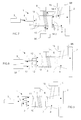
- the plasma recharging device 1 comprises a torch with plasma 3, coupled by a pipe 4 to a gas supply module 5 plasmagen, such as oxygen, nitrogen or argon, or a combination of two of them, and surrounded by a winding supplied with high current frequency by a generator 6.
- a gas supply module 5 plasmagen, such as oxygen, nitrogen or argon, or a combination of two of them, and surrounded by a winding supplied with high current frequency by a generator 6.
- the plasma gas injected into the plasma torch 3 is a mixture of nitrogen and oxygen.
- part of the plasma gas is generally introduced into a central part 10 of the plasma torch, while the complementary part is introduced with a different flow at the periphery 11 of the central part 10. It is important to note that there is no dividing wall between the central 10 and peripheral 11 parts.
- a plasma of ionized gas at high temperature is generated inside the plasma torch 3, and delivered to the end of an outlet nozzle 7 of this torch.
- the SiO 2 grain injector (not shown) delivers its grains in an interaction zone 8 located between the outlet nozzle 7 and the preform mandrel 2, which moves in translation and in rotation in a controlled manner under the action of the support and displacement device (not shown). Under the action of the heat released by the plasma at the outlet of the torch 3, the grains of SiO 2 sublimate and come to stick on the preform mandrel 2 which can thus be recharged with silica.
- the recharging device 1 further comprises at at least one module 9 for supplying reducing element (s).
- the supply module 5 supplies gas plasmagen (preferably in air (containing mainly nitrogen and oxygen in selected proportions)) central zones 10 and peripheral 11 of the plasma torch 3, via line 4, while the supply module 9 supplies the peripheral zone 11 with element (s) reducer (s) via pipes 12.
- the reducing element and the plasma gas are mixed inside the plasma torch 3.
- any element can be used solid, liquid or gas, including decomposition, due to high plasma temperatures, releases the reducing effect of such elements as, for example, hydrogen.
- each reducing element is preferably introduced in the gaseous state.
- Each gaseous reducing element is preferably chosen from hydrogen (H 2 ), ammonia (NH 3 ), carbon monoxide (CO) and light hydrocarbons, in particular methane (CH 4 ), ethane (C 2 H 6 ), propane (C 3 H 8 ) and butane (C 4 H 10 ).
- each solid reducing element is preferably chosen from urea, ammonium fluoride (NH 4 F) and their derivatives containing bonds capable of oxidizing easily.
- the nitrogen oxides generated by the interaction between oxygen and nitrogen contained in the enclosure, due to the high temperatures of the plasma generated by the torch 3, are reduced by the reducing elements, introduced into the recharging device 1 upstream of the exit from the confined enclosure, according to one or the other of the chemical formulas mentioned below: 2 NO + 2 H 2 ⁇ N 2 + 2 H 2 O 2 NO 2 + 4 NH 3 + 0 2 ⁇ 3 N 2 + 6 H 2 O
- the power supply module 9 supplies element (s) reducer (s), preferably accompanied by air, with the lines 12, not only the peripheral zone 11, but also the central zone 10.
- the power supply module 9 has two independent sub-parts supplying respectively the central 10 and peripheral 11 zones of the plasma torch 3 in different reducing elements (preferably accompanied by air).
- the supply module 9 is subdivided into at least two sub-modules 9A and 9B which supply reducing element (s), preferably different, not only the upstream part of the plasma torch 3 by the pipes 12, but also the downstream part of the torch, at the end of its outlet nozzle 7, by pipes 13.
- the end of the outlet nozzle 7 in fact comprises at least one inlet 14 connected to a line 13 and arranged so as to deliver one or more reducing elements at the outlet of the plasma torch 7, at at least one location.
- the upstream part of the plasma torch 3 is supplied with air and hydrogen by the supply sub-module 9A, via the pipes 12, while the inputs 14 of the outlet nozzle 7 are supplied with ammonia ( NH 3 ) via the supply sub-module 9B, via lines 13.
- three inputs 14-1 are provided to 14-3 to introduce the reducing element or elements in at least three places, for example so as to generate a curtain of reducing element (s) likely to be crossed by plasma. But, of course, we could allow two or four entrances, or even more.
- the outlet nozzle 7 could be fitted with a multitude of holes ensuring diffusion homogeneous and distributed reducing elements at the end of exit from the plasma torch 3.
- the supply module 9 does not supply element (s) reducer (s) than the downstream part of the plasma torch 3, at its nozzle outlet 7, via lines 13, as in the example in FIG. 4.
- the outlet nozzle 7 comprises at least one inlet 14 connected to a pipe 13 and arranged so as to deliver one or more reducing elements to the exit from the plasma torch 7, in at least one location.
- the supply module 5 can be used to supply the plasma torch 3 either only with plasma gas such as oxygen, nitrogen or argon, or a combination of two, or with gas serving both reducing gas and plasma gas, such as for example hydrogen (H 2 ) and / or ammonia (NH 3 ), preferably accompanied by air.
- plasma gas such as oxygen, nitrogen or argon, or a combination of two, or with gas serving both reducing gas and plasma gas, such as for example hydrogen (H 2 ) and / or ammonia (NH 3 ), preferably accompanied by air.
- This example starts from the recharging device 1 of FIG. 6 and includes a first power supply module 9A which supplies the reducing element (s) with the downstream part of the plasma torch 3, at its outlet nozzle 7, by lines 13, and a second supply module 9B which supplies reducing element (s) of the interaction zone 8, by an injector 15.
- a first power supply module 9A which supplies the reducing element (s) with the downstream part of the plasma torch 3, at its outlet nozzle 7, by lines 13, and a second supply module 9B which supplies reducing element (s) of the interaction zone 8, by an injector 15.
- the injector 15 may be that which is used to introduce the grains of SiO 2 .
- the power module 5 can be used to supply the plasma torch 3 either with gas only plasma, either as a gas serving as both a reducing gas and a gas plasma.
- This embodiment is suitable for the introduction of element (s) solid or gaseous reducer (s) downstream of the torch 3.
- FIG. 8 we now refer to Figure 8 to describe a sixth example for producing a device according to the invention. It is actually a variant of the device described above with reference to FIG. 1 or a variant of the device described above with reference to FIG. 7.
- the recharging device 1 comprises a first module 9A power supply which supplies reducing element (s) to the peripheral zone 11 of the plasma torch 3, via lines 12, and a second module 9B power supply which supplies reducing element (s) to the interaction zone 8, by an injector 15.
- the injector 15 may be that which is used to introduce the grains of SiO 2 .
- This embodiment is suitable for the introduction of element (s) gaseous reducer (s) upstream of the torch 3 and of element (s) solid or gaseous reducer (s) downstream of the torch 3.
- the recharging device 1 comprises a supply module 9 which supplies the interaction zone 8 with reducing element (s), by an injector 15 (which may be that used to introduce the grains of SiO 2 ).
- the supply module 5 can be used to supply the plasma torch 3 either solely with plasma gas (and air), or with gas acting both as a reducing gas and of plasma gas.
- This embodiment is also suitable for the introduction reducing element (s) in the gaseous state upstream of the torch 3 and reducing element (s) in solid or gaseous state downstream of the torch 3.
- charging device 1 can be considered from combinations of the different embodiments power modules 5, 9, 9A and 9B described above with reference in Figures 1 to 9.
- the invention also relates to a plasma recharging method. a preform 2 for optical fiber.
- This process consists, on the one hand, of depositing a refill material on a primary preform 2, to be recharged, using a plasma torch 3 supplied with plasma gas and in the presence of a silica-based material, and on the other hand, to introduce upstream of the primary preform 2 at least one reducing element making it possible to induce a reduction in oxides by reaction of nitrogen produced by the interaction between nitrogen and oxygen (contained in the enclosure), in the presence of the plasma generated by the torch.
Landscapes
- Engineering & Computer Science (AREA)
- Chemical & Material Sciences (AREA)
- Life Sciences & Earth Sciences (AREA)
- General Life Sciences & Earth Sciences (AREA)
- Geochemistry & Mineralogy (AREA)
- Manufacturing & Machinery (AREA)
- Materials Engineering (AREA)
- Organic Chemistry (AREA)
- Physics & Mathematics (AREA)
- Plasma & Fusion (AREA)
- Chemical Kinetics & Catalysis (AREA)
- General Chemical & Material Sciences (AREA)
- Manufacture, Treatment Of Glass Fibers (AREA)
- Physical Or Chemical Processes And Apparatus (AREA)
- Surface Treatment Of Glass Fibres Or Filaments (AREA)
- Plasma Technology (AREA)
- Glass Compositions (AREA)
Abstract
Description
- des moyens d'alimentation secondaire couplés à la torche à plasma et agencés de manière à introduire l'un au moins des éléments réducteurs à l'intérieur de la torche à plasma, en amont d'une buse de sortie, comme par exemple dans une zone centrale dans laquelle circule le gaz plasmagène et/ou à la périphérie de cette zone centrale ;
- des moyens d'alimentation secondaire couplés à la torche à plasma et agencés de manière à introduire l'un au moins des éléments réducteurs au niveau d'une extrémité de la buse de sortie de la torche à plasma, comme par exemple en au moins un endroit à la périphérie de l'extrémité de cette buse de sortie ;
- des moyens d'alimentation secondaire couplés à la torche à plasma et agencés de manière à introduire l'un au moins des éléments réducteurs en au moins un endroit d'une zone d'interaction comprise entre la buse de sortie de la torche à plasma et la préforme primaire.
- la figure 1 illustre de façon schématique un premier exemple de réalisation d'un dispositif selon l'invention,
- la figure 2 est une vue du dessus de l'extrémité de la buse de sortie de la torche à plasma du dispositif de la figure 1,
- la figure 3 illustre de façon schématique un deuxième exemple de réalisation d'un dispositif selon l'invention,
- la figure 4 illustre de façon schématique un troisième exemple de réalisation d'un dispositif selon l'invention,
- la figure 5 est une vue du dessus d'un exemple de réalisation d'extrémité de buse de sortie pour la torche à plasma du dispositif des figures 4, 6 et 7,
- la figure 6 illustre de façon schématique un quatrième exemple de réalisation d'un dispositif selon l'invention,
- la figure 7 illustre de façon schématique un cinquième exemple de réalisation d'un dispositif selon l'invention,
- la figure 8 illustre de façon schématique un sixième exemple de réalisation d'un dispositif selon l'invention, et
- la figure 9 illustre de façon schématique un septième exemple de réalisation d'un dispositif selon l'invention.
Claims (20)
- Procédé de recharge par plasma d'une préforme (2) pour fibre optique, dans lequel on dépose un matériau de recharge sur une préforme primaire (2), à recharger, à l'aide d'une torche à plasma (3) alimentée en gaz plasmagène et en présence d'un matériau à base de silice, caractérisé en ce que l'on introduit en amont de ladite préforme primaire (2) au moins un élément réducteur propre à induire par réaction une réduction des oxydes d'azote produits par interaction entre de l'azote et de l'oxygène, en présence du plasma généré par la torche.
- Procédé selon la revendication 1, dans lequel l'un au moins des éléments réducteurs est introduit à l'état gazeux.
- Procédé selon la revendication 2, dans lequel ledit élément réducteur gazeux constitue une partie au moins dudit gaz plasmagène.
- Procédé selon l'une des revendications 2 et 3, dans lequel ledit élément réducteur gazeux est choisi dans un groupe comprenant au moins l'hydrogène, l'ammoniac, le monoxyde de carbone et les hydrocarbures légers, en particulier le méthane, l'éthane, le propane et le butane.
- Procédé selon l'une des revendications 1 à 4, dans lequel l'un au moins des éléments réducteurs est introduit à l'état solide.
- Procédé selon la revendication 5, dans lequel ledit élément réducteur solide est choisi dans un groupe comprenant au moins l'urée et le fluorure d'ammonium.
- Procédé selon l'une des revendications 1 à 6, dans lequel l'un au moins desdits éléments réducteurs est introduit dans ladite torche à plasma (3), en amont d'une buse de sortie (7).
- Procédé selon la revendication 7, dans lequel ledit élément réducteur est introduit dans une zone centrale (10) de la torche à plasma (3) dans laquelle circule ledit gaz plasmagène.
- Procédé selon la revendication 8, dans lequel ledit élément réducteur est introduit dans ladite zone centrale (10) sensiblement en même temps que ledit gaz plasmagène.
- Procédé selon l'une des revendications 7 à 9, dans lequel ledit élément réducteur est introduit à la périphérie (11 ) de ladite zone centrale (10) de la torche à plasma (3).
- Procédé selon l'une des revendications 1 à 10, dans lequel l'un au moins desdits éléments réducteurs est introduit dans ladite torche à plasma (3), au niveau d'une extrémité de ladite buse de sortie (7).
- Procédé selon la revendication 11, dans lequel ledit élément réducteur est introduit à la périphérie de ladite extrémité de la buse de sortie (7), en au moins un endroit.
- Procédé selon l'une des revendications 1 à 12, dans lequel l'un au moins desdits éléments réducteurs est introduit dans une zone d'interaction (8) comprise entre ladite buse de sortie (7) de la torche à plasma (3) et ladite préforme primaire (2), en au moins un endroit.
- Dispositif (1) de recharge par plasma d'une préforme (2) pour fibre optique, comprenant une torche à plasma (3), alimentée en gaz plasmagène par des moyens d'alimentation primaire (5), et agencée pour permettre le dépôt d'un matériau de recharge sur une préforme primaire (2), à recharger, en présence d'un matériau à base de silice, caractérisé en ce qu'il comprend des moyens d'alimentation secondaire (9) agencés pour introduire en amont de ladite préforme primaire (2) au moins un élément réducteur propre à induire par réaction une réduction des oxydes d'azote produits par interaction entre de l'azote et de l'oxygène, en présence du plasma généré par la torche.
- Dispositif selon la revendication 14, dans lequel lesdits moyens d'alimentation secondaire (9) sont couplés à ladite torche à plasma (3) et agencés pour introduire l'un au moins desdits éléments réducteurs à l'intérieur de ladite torche à plasma, en amont d'une buse de sortie (7).
- Dispositif selon la revendication 15, dans lequel lesdits moyens d'alimentation secondaire (9) sont agencés pour introduire ledit élément réducteur dans une zone centrale (10) de la torche à plasma (3) dans laquelle circule ledit gaz plasmagène.
- Dispositif selon l'une des revendications 14 à 16, dans lequel lesdits moyens d'alimentation secondaire (9) sont couplés à ladite torche à plasma (3) et agencés pour introduire ledit élément réducteur à la périphérie (11 ) de ladite zone centrale (10) de la torche à plasma (3).
- Dispositif selon l'une des revendications 14 à 16, dans lequel lesdits moyens d'alimentation secondaire (9) sont couplés à ladite torche à plasma (3) et agencés pour introduire l'un au moins desdits éléments réducteurs au niveau d'une extrémité d'une buse de sortie (7) de ladite torche à plasma (3).
- Dispositif selon la revendication 18, dans lequel lesdits moyens d'alimentation secondaire (9) sont couplés à ladite torche à plasma (3) et agencés pour introduire ledit élément réducteur à la périphérie de ladite extrémité de la buse de sortie (7), en au moins un endroit.
- Dispositif selon l'une des revendications 14 à 19, dans lequel lesdits moyens d'alimentation secondaire (9) sont couplés à ladite torche à plasma (3) et agencés pour introduire l'un au moins desdits éléments réducteurs dans une zone d'interaction (8) comprise entre ladite buse de sortie (7) de la torche à plasma (3) et ladite préforme primaire (2), en au moins un endroit.
Applications Claiming Priority (2)
| Application Number | Priority Date | Filing Date | Title |
|---|---|---|---|
| FR0215124A FR2847893B1 (fr) | 2002-12-02 | 2002-12-02 | Procede et dispositif de recharge par plasma d'une preforme pour fibre optique, a oxydes d'azote reduits |
| FR0215124 | 2002-12-02 |
Publications (2)
| Publication Number | Publication Date |
|---|---|
| EP1426340A1 true EP1426340A1 (fr) | 2004-06-09 |
| EP1426340B1 EP1426340B1 (fr) | 2010-10-27 |
Family
ID=32309894
Family Applications (1)
| Application Number | Title | Priority Date | Filing Date |
|---|---|---|---|
| EP03292913A Expired - Lifetime EP1426340B1 (fr) | 2002-12-02 | 2003-11-25 | Procédé de recharge par plasma d'une préforme pour fibre optique |
Country Status (6)
| Country | Link |
|---|---|
| US (1) | US7629032B2 (fr) |
| EP (1) | EP1426340B1 (fr) |
| CN (1) | CN100344562C (fr) |
| AT (1) | ATE486050T1 (fr) |
| DE (1) | DE60334669D1 (fr) |
| FR (1) | FR2847893B1 (fr) |
Cited By (1)
| Publication number | Priority date | Publication date | Assignee | Title |
|---|---|---|---|---|
| WO2010070062A1 (fr) * | 2008-12-19 | 2010-06-24 | J-Fiber Gmbh | Torche à plasma tubulaire à plusieurs buses, pour fabriquer des ébauches en tant que semi-produits pour fibres optiques |
Citations (6)
| Publication number | Priority date | Publication date | Assignee | Title |
|---|---|---|---|---|
| US4402720A (en) * | 1980-01-22 | 1983-09-06 | Nippon Telegraph & Telephone Public Corporation | Process for preparing glass preform for optical fiber |
| GB2134896A (en) | 1983-02-10 | 1984-08-22 | Int Standard Electric Corp | Optical waveguide preform fabrication |
| US4689212A (en) | 1986-05-14 | 1987-08-25 | Polaroid Corporation | Method for forming doped optical preforms |
| EP0401742A1 (fr) * | 1989-06-05 | 1990-12-12 | Alcatel | Procédé et dispositif de depot externe par plasma de silice exempte d'ions hydroxyles |
| JPH06321552A (ja) | 1993-05-10 | 1994-11-22 | Fujikura Ltd | フッ素ドープ石英ガラスの製造方法 |
| WO1999052832A1 (fr) * | 1998-04-10 | 1999-10-21 | Fibercore, Inc. | Procede permettant de fabriquer une preforme de fibre optique |
Family Cites Families (9)
| Publication number | Priority date | Publication date | Assignee | Title |
|---|---|---|---|---|
| GB1255498A (en) * | 1968-08-13 | 1971-12-01 | Monsanto Chemicals | Production of finely divided silica |
| JPS6321552A (ja) * | 1986-07-15 | 1988-01-29 | Mitsubishi Electric Corp | オゾン反応試験装置 |
| FR2616614B1 (fr) * | 1987-06-10 | 1989-10-20 | Air Liquide | Torche a plasma micro-onde, dispositif comportant une telle torche et procede pour la fabrication de poudre les mettant en oeuvre |
| AU640996B2 (en) * | 1990-03-29 | 1993-09-09 | Societe Anonyme Dite Alcatel Alsthom Compagnie Generale D'electricite | A method of fabricating preforms for making optical fibers by drawing |
| US5174982A (en) * | 1990-12-12 | 1992-12-29 | Dow Corning Corporation | Control of carbon balance in a silicon smelting furnace |
| FR2713621B1 (fr) * | 1993-12-14 | 1996-01-05 | Alcatel Fibres Optiques | Procédé de recharge par plasma d'une préforme pour fibre optique et fibre optique issue de la préforme rechargée selon ce procédé. |
| US6109065A (en) * | 1998-04-22 | 2000-08-29 | Lucent Technologies, Inc. | Method of making optical waveguide devices using perchloryl fluoride to make soot |
| KR100450928B1 (ko) * | 2001-07-23 | 2004-10-02 | 삼성전자주식회사 | 수정된 화학기상 증착법을 이용한 광섬유 모재의 제조장치 및 방법 |
| US20040057692A1 (en) * | 2002-08-28 | 2004-03-25 | Ball Laura J. | Low loss optical fiber and method for making same |
-
2002
- 2002-12-02 FR FR0215124A patent/FR2847893B1/fr not_active Expired - Fee Related
-
2003
- 2003-11-25 DE DE60334669T patent/DE60334669D1/de not_active Expired - Lifetime
- 2003-11-25 EP EP03292913A patent/EP1426340B1/fr not_active Expired - Lifetime
- 2003-11-25 AT AT03292913T patent/ATE486050T1/de not_active IP Right Cessation
- 2003-12-02 CN CNB2003101169593A patent/CN100344562C/zh not_active Expired - Fee Related
- 2003-12-02 US US10/725,003 patent/US7629032B2/en not_active Expired - Fee Related
Patent Citations (6)
| Publication number | Priority date | Publication date | Assignee | Title |
|---|---|---|---|---|
| US4402720A (en) * | 1980-01-22 | 1983-09-06 | Nippon Telegraph & Telephone Public Corporation | Process for preparing glass preform for optical fiber |
| GB2134896A (en) | 1983-02-10 | 1984-08-22 | Int Standard Electric Corp | Optical waveguide preform fabrication |
| US4689212A (en) | 1986-05-14 | 1987-08-25 | Polaroid Corporation | Method for forming doped optical preforms |
| EP0401742A1 (fr) * | 1989-06-05 | 1990-12-12 | Alcatel | Procédé et dispositif de depot externe par plasma de silice exempte d'ions hydroxyles |
| JPH06321552A (ja) | 1993-05-10 | 1994-11-22 | Fujikura Ltd | フッ素ドープ石英ガラスの製造方法 |
| WO1999052832A1 (fr) * | 1998-04-10 | 1999-10-21 | Fibercore, Inc. | Procede permettant de fabriquer une preforme de fibre optique |
Non-Patent Citations (1)
| Title |
|---|
| PATENT ABSTRACTS OF JAPAN vol. 1995, no. 02 31 March 1995 (1995-03-31) * |
Cited By (1)
| Publication number | Priority date | Publication date | Assignee | Title |
|---|---|---|---|---|
| WO2010070062A1 (fr) * | 2008-12-19 | 2010-06-24 | J-Fiber Gmbh | Torche à plasma tubulaire à plusieurs buses, pour fabriquer des ébauches en tant que semi-produits pour fibres optiques |
Also Published As
| Publication number | Publication date |
|---|---|
| US7629032B2 (en) | 2009-12-08 |
| FR2847893A1 (fr) | 2004-06-04 |
| CN1504433A (zh) | 2004-06-16 |
| US20040107898A1 (en) | 2004-06-10 |
| ATE486050T1 (de) | 2010-11-15 |
| CN100344562C (zh) | 2007-10-24 |
| EP1426340B1 (fr) | 2010-10-27 |
| DE60334669D1 (de) | 2010-12-09 |
| FR2847893B1 (fr) | 2006-05-05 |
Similar Documents
| Publication | Publication Date | Title |
|---|---|---|
| EP1379810B1 (fr) | Procédé de combustion comportant des injections séparées de combustible et d'oxydant et ensemble brûleur pour la mise en oeuvre de ce procédé | |
| EP1934309B1 (fr) | Dispositif et procédé de gazéification de la biomasse et de déchets organiques sous haute température et avec apport d'énergie extérieure pour la génération d'un gaz de synthèse de haute qualité. | |
| EP1144915A1 (fr) | Appareil de type torchere et procede pour la combustion de gaz | |
| CA2781968A1 (fr) | Procede et dispositif de destruction thermique de composes organiques par un plasma d'induction. | |
| FR2715460A1 (fr) | Structure de brûleur. | |
| RU2000122832A (ru) | Способ изменения длины когерентной струи | |
| WO2008074961A2 (fr) | Four de fusion de verre | |
| EP0406071A1 (fr) | Dispositif et procédé de fabrication de gaz de synthèse par combustion et son application | |
| CA2657537C (fr) | Bruleur et procede pour la mise en oeuvre alternee d'une oxycombustion et d'une aerocombustion | |
| EP0989362B1 (fr) | Procédé de chauffage d'un four | |
| EP1618334B1 (fr) | Procede de combustion etagee d un combustible liquide et d'un oxydant dans un four | |
| EP1426340B1 (fr) | Procédé de recharge par plasma d'une préforme pour fibre optique | |
| EP2407716A1 (fr) | Brûleur pour le traitement d'un gaz acide combustible et four à réaction adapté | |
| FR2595791A1 (fr) | Bruleur a faible emission de gaz polluants | |
| FR2825448A1 (fr) | Generateur thermique permettant de limiter les emissions d'oxydes d'azote par recombustion des fumees et procede pour la mise en oeuvre d'un tel generateur | |
| EP1122497A1 (fr) | Brûleur aéro-oxy-gaz à flamme stabilisée, et bloc-ouvreau équipé d'un tel brûleur | |
| EP0375491A1 (fr) | Procédé et installation de traitement thermique de cémentation, carbonitruration ou chauffage avant trempe de pièces métalliques | |
| EP0980849A1 (fr) | Procédé pour purifier de la silice et application au dépôt de silice purifiée sur une préforme de fibre optique | |
| WO2006008421A2 (fr) | Traitement d'effluents gazeux par plasma a pression atmospherique | |
| EP0834049B1 (fr) | Procede de fusion d'une charge dans un four electrique a arc | |
| WO2007057588A1 (fr) | Procede d'injection supersonique d'oxygene dans un four | |
| FR2851032A1 (fr) | Perfectionnement au bruleur comportant un stabilisateur de flamme et au moins deux conduits d'air primaire, axial et en rotation, concentriques autour d'au moins une alimentation en combustible | |
| WO1992000391A1 (fr) | Procede de rechauffage d'un bain d'acier liquide et dispositif pour la mise en ×uvre de ce procede | |
| FR2797738A1 (fr) | Procede d'injection d'un gaz supersonique dans un four a arc electrique et four a arc pour la mise en oeuvre de ce procede | |
| EP0390766A1 (fr) | Procédé pour injecter un combustible auxiliaire dans un haut fourneau |
Legal Events
| Date | Code | Title | Description |
|---|---|---|---|
| PUAI | Public reference made under article 153(3) epc to a published international application that has entered the european phase |
Free format text: ORIGINAL CODE: 0009012 |
|
| AK | Designated contracting states |
Kind code of ref document: A1 Designated state(s): AT BE BG CH CY CZ DE DK EE ES FI FR GB GR HU IE IT LI LU MC NL PT RO SE SI SK TR |
|
| AX | Request for extension of the european patent |
Extension state: AL LT LV MK |
|
| 17P | Request for examination filed |
Effective date: 20041026 |
|
| AKX | Designation fees paid |
Designated state(s): AT BE BG CH CY CZ DE DK EE ES FI FR GB GR HU IE IT LI LU MC NL PT RO SE SI SK TR |
|
| RAP1 | Party data changed (applicant data changed or rights of an application transferred) |
Owner name: DRAKA COMTEQ B.V. |
|
| RAP1 | Party data changed (applicant data changed or rights of an application transferred) |
Owner name: DRAKA COMTEQ B.V. |
|
| RAP1 | Party data changed (applicant data changed or rights of an application transferred) |
Owner name: DRAKA COMTEQ B.V. |
|
| GRAP | Despatch of communication of intention to grant a patent |
Free format text: ORIGINAL CODE: EPIDOSNIGR1 |
|
| RTI1 | Title (correction) |
Free format text: PROCESS FOR OVERCLADDING AN OPTICAL FIBRE PREFORM BY PLASMA |
|
| GRAS | Grant fee paid |
Free format text: ORIGINAL CODE: EPIDOSNIGR3 |
|
| GRAA | (expected) grant |
Free format text: ORIGINAL CODE: 0009210 |
|
| AK | Designated contracting states |
Kind code of ref document: B1 Designated state(s): AT BE BG CH CY CZ DE DK EE ES FI FR GB GR HU IE IT LI LU MC NL PT RO SE SI SK TR |
|
| REG | Reference to a national code |
Ref country code: GB Ref legal event code: FG4D Free format text: NOT ENGLISH |
|
| REG | Reference to a national code |
Ref country code: CH Ref legal event code: EP |
|
| REG | Reference to a national code |
Ref country code: IE Ref legal event code: FG4D Free format text: LANGUAGE OF EP DOCUMENT: FRENCH |
|
| REF | Corresponds to: |
Ref document number: 60334669 Country of ref document: DE Date of ref document: 20101209 Kind code of ref document: P |
|
| REG | Reference to a national code |
Ref country code: NL Ref legal event code: VDEP Effective date: 20101027 |
|
| REG | Reference to a national code |
Ref country code: IE Ref legal event code: FD4D |
|
| BERE | Be: lapsed |
Owner name: DRAKA COMTEQ B.V. Effective date: 20101130 |
|
| PG25 | Lapsed in a contracting state [announced via postgrant information from national office to epo] |
Ref country code: PT Free format text: LAPSE BECAUSE OF FAILURE TO SUBMIT A TRANSLATION OF THE DESCRIPTION OR TO PAY THE FEE WITHIN THE PRESCRIBED TIME-LIMIT Effective date: 20110228 Ref country code: NL Free format text: LAPSE BECAUSE OF FAILURE TO SUBMIT A TRANSLATION OF THE DESCRIPTION OR TO PAY THE FEE WITHIN THE PRESCRIBED TIME-LIMIT Effective date: 20101027 Ref country code: FI Free format text: LAPSE BECAUSE OF FAILURE TO SUBMIT A TRANSLATION OF THE DESCRIPTION OR TO PAY THE FEE WITHIN THE PRESCRIBED TIME-LIMIT Effective date: 20101027 Ref country code: SI Free format text: LAPSE BECAUSE OF FAILURE TO SUBMIT A TRANSLATION OF THE DESCRIPTION OR TO PAY THE FEE WITHIN THE PRESCRIBED TIME-LIMIT Effective date: 20101027 Ref country code: AT Free format text: LAPSE BECAUSE OF FAILURE TO SUBMIT A TRANSLATION OF THE DESCRIPTION OR TO PAY THE FEE WITHIN THE PRESCRIBED TIME-LIMIT Effective date: 20101027 Ref country code: SE Free format text: LAPSE BECAUSE OF FAILURE TO SUBMIT A TRANSLATION OF THE DESCRIPTION OR TO PAY THE FEE WITHIN THE PRESCRIBED TIME-LIMIT Effective date: 20101027 Ref country code: BG Free format text: LAPSE BECAUSE OF FAILURE TO SUBMIT A TRANSLATION OF THE DESCRIPTION OR TO PAY THE FEE WITHIN THE PRESCRIBED TIME-LIMIT Effective date: 20110127 |
|
| PG25 | Lapsed in a contracting state [announced via postgrant information from national office to epo] |
Ref country code: MC Free format text: LAPSE BECAUSE OF NON-PAYMENT OF DUE FEES Effective date: 20101130 Ref country code: GR Free format text: LAPSE BECAUSE OF FAILURE TO SUBMIT A TRANSLATION OF THE DESCRIPTION OR TO PAY THE FEE WITHIN THE PRESCRIBED TIME-LIMIT Effective date: 20110128 |
|
| REG | Reference to a national code |
Ref country code: CH Ref legal event code: PL |
|
| PG25 | Lapsed in a contracting state [announced via postgrant information from national office to epo] |
Ref country code: EE Free format text: LAPSE BECAUSE OF FAILURE TO SUBMIT A TRANSLATION OF THE DESCRIPTION OR TO PAY THE FEE WITHIN THE PRESCRIBED TIME-LIMIT Effective date: 20101027 Ref country code: CZ Free format text: LAPSE BECAUSE OF FAILURE TO SUBMIT A TRANSLATION OF THE DESCRIPTION OR TO PAY THE FEE WITHIN THE PRESCRIBED TIME-LIMIT Effective date: 20101027 Ref country code: ES Free format text: LAPSE BECAUSE OF FAILURE TO SUBMIT A TRANSLATION OF THE DESCRIPTION OR TO PAY THE FEE WITHIN THE PRESCRIBED TIME-LIMIT Effective date: 20110207 Ref country code: CH Free format text: LAPSE BECAUSE OF NON-PAYMENT OF DUE FEES Effective date: 20101130 Ref country code: LI Free format text: LAPSE BECAUSE OF NON-PAYMENT OF DUE FEES Effective date: 20101130 Ref country code: IE Free format text: LAPSE BECAUSE OF FAILURE TO SUBMIT A TRANSLATION OF THE DESCRIPTION OR TO PAY THE FEE WITHIN THE PRESCRIBED TIME-LIMIT Effective date: 20101027 |
|
| PG25 | Lapsed in a contracting state [announced via postgrant information from national office to epo] |
Ref country code: DK Free format text: LAPSE BECAUSE OF FAILURE TO SUBMIT A TRANSLATION OF THE DESCRIPTION OR TO PAY THE FEE WITHIN THE PRESCRIBED TIME-LIMIT Effective date: 20101027 Ref country code: RO Free format text: LAPSE BECAUSE OF FAILURE TO SUBMIT A TRANSLATION OF THE DESCRIPTION OR TO PAY THE FEE WITHIN THE PRESCRIBED TIME-LIMIT Effective date: 20101027 Ref country code: BE Free format text: LAPSE BECAUSE OF NON-PAYMENT OF DUE FEES Effective date: 20101130 Ref country code: SK Free format text: LAPSE BECAUSE OF FAILURE TO SUBMIT A TRANSLATION OF THE DESCRIPTION OR TO PAY THE FEE WITHIN THE PRESCRIBED TIME-LIMIT Effective date: 20101027 |
|
| PLBE | No opposition filed within time limit |
Free format text: ORIGINAL CODE: 0009261 |
|
| STAA | Information on the status of an ep patent application or granted ep patent |
Free format text: STATUS: NO OPPOSITION FILED WITHIN TIME LIMIT |
|
| 26N | No opposition filed |
Effective date: 20110728 |
|
| REG | Reference to a national code |
Ref country code: DE Ref legal event code: R097 Ref document number: 60334669 Country of ref document: DE Effective date: 20110728 |
|
| PG25 | Lapsed in a contracting state [announced via postgrant information from national office to epo] |
Ref country code: IT Free format text: LAPSE BECAUSE OF FAILURE TO SUBMIT A TRANSLATION OF THE DESCRIPTION OR TO PAY THE FEE WITHIN THE PRESCRIBED TIME-LIMIT Effective date: 20101027 |
|
| PG25 | Lapsed in a contracting state [announced via postgrant information from national office to epo] |
Ref country code: CY Free format text: LAPSE BECAUSE OF FAILURE TO SUBMIT A TRANSLATION OF THE DESCRIPTION OR TO PAY THE FEE WITHIN THE PRESCRIBED TIME-LIMIT Effective date: 20101027 |
|
| PG25 | Lapsed in a contracting state [announced via postgrant information from national office to epo] |
Ref country code: HU Free format text: LAPSE BECAUSE OF FAILURE TO SUBMIT A TRANSLATION OF THE DESCRIPTION OR TO PAY THE FEE WITHIN THE PRESCRIBED TIME-LIMIT Effective date: 20110428 Ref country code: LU Free format text: LAPSE BECAUSE OF NON-PAYMENT OF DUE FEES Effective date: 20101125 |
|
| PG25 | Lapsed in a contracting state [announced via postgrant information from national office to epo] |
Ref country code: TR Free format text: LAPSE BECAUSE OF FAILURE TO SUBMIT A TRANSLATION OF THE DESCRIPTION OR TO PAY THE FEE WITHIN THE PRESCRIBED TIME-LIMIT Effective date: 20101027 |
|
| PGFP | Annual fee paid to national office [announced via postgrant information from national office to epo] |
Ref country code: FR Payment date: 20121130 Year of fee payment: 10 Ref country code: DE Payment date: 20121121 Year of fee payment: 10 |
|
| PGFP | Annual fee paid to national office [announced via postgrant information from national office to epo] |
Ref country code: GB Payment date: 20121120 Year of fee payment: 10 |
|
| REG | Reference to a national code |
Ref country code: DE Ref legal event code: R119 Ref document number: 60334669 Country of ref document: DE |
|
| GBPC | Gb: european patent ceased through non-payment of renewal fee |
Effective date: 20131125 |
|
| REG | Reference to a national code |
Ref country code: FR Ref legal event code: ST Effective date: 20140731 |
|
| PG25 | Lapsed in a contracting state [announced via postgrant information from national office to epo] |
Ref country code: DE Free format text: LAPSE BECAUSE OF NON-PAYMENT OF DUE FEES Effective date: 20140603 |
|
| REG | Reference to a national code |
Ref country code: DE Ref legal event code: R119 Ref document number: 60334669 Country of ref document: DE Effective date: 20140603 |
|
| PG25 | Lapsed in a contracting state [announced via postgrant information from national office to epo] |
Ref country code: GB Free format text: LAPSE BECAUSE OF NON-PAYMENT OF DUE FEES Effective date: 20131125 Ref country code: FR Free format text: LAPSE BECAUSE OF NON-PAYMENT OF DUE FEES Effective date: 20131202 |