EP1426235A1 - Véhicule automobile transformable en véhicule à benne ouverte vers le haut - Google Patents

Véhicule automobile transformable en véhicule à benne ouverte vers le haut Download PDF

Info

Publication number
EP1426235A1
EP1426235A1 EP03293017A EP03293017A EP1426235A1 EP 1426235 A1 EP1426235 A1 EP 1426235A1 EP 03293017 A EP03293017 A EP 03293017A EP 03293017 A EP03293017 A EP 03293017A EP 1426235 A1 EP1426235 A1 EP 1426235A1
Authority
EP
European Patent Office
Prior art keywords
cover
motor vehicle
frame
floor
trunk
Prior art date
Legal status (The legal status is an assumption and is not a legal conclusion. Google has not performed a legal analysis and makes no representation as to the accuracy of the status listed.)
Withdrawn
Application number
EP03293017A
Other languages
German (de)
English (en)
Inventor
Pascal Belanger
Current Assignee (The listed assignees may be inaccurate. Google has not performed a legal analysis and makes no representation or warranty as to the accuracy of the list.)
PSA Automobiles SA
Original Assignee
Peugeot Citroen Automobiles SA
Priority date (The priority date is an assumption and is not a legal conclusion. Google has not performed a legal analysis and makes no representation as to the accuracy of the date listed.)
Filing date
Publication date
Application filed by Peugeot Citroen Automobiles SA filed Critical Peugeot Citroen Automobiles SA
Publication of EP1426235A1 publication Critical patent/EP1426235A1/fr
Withdrawn legal-status Critical Current

Links

Images

Classifications

    • BPERFORMING OPERATIONS; TRANSPORTING
    • B60VEHICLES IN GENERAL
    • B60PVEHICLES ADAPTED FOR LOAD TRANSPORTATION OR TO TRANSPORT, TO CARRY, OR TO COMPRISE SPECIAL LOADS OR OBJECTS
    • B60P3/00Vehicles adapted to transport, to carry or to comprise special loads or objects
    • B60P3/42Vehicles adapted to transport, to carry or to comprise special loads or objects convertible from one use to a different one
    • B60P3/423Vehicles adapted to transport, to carry or to comprise special loads or objects convertible from one use to a different one from transport of persons to transport of goods
    • BPERFORMING OPERATIONS; TRANSPORTING
    • B60VEHICLES IN GENERAL
    • B60RVEHICLES, VEHICLE FITTINGS, OR VEHICLE PARTS, NOT OTHERWISE PROVIDED FOR
    • B60R5/00Compartments within vehicle body primarily intended or sufficiently spacious for trunks, suit-cases, or the like
    • B60R5/04Compartments within vehicle body primarily intended or sufficiently spacious for trunks, suit-cases, or the like arranged at rear of vehicle
    • B60R5/041Compartments within vehicle body primarily intended or sufficiently spacious for trunks, suit-cases, or the like arranged at rear of vehicle extensible externally of the vehicle body, e.g. to create an open luggage compartment of increased capacity

Definitions

  • the present invention relates to a motor vehicle convertible into an open-top tipper motor vehicle.
  • Sedan or coupe type motor vehicles include, conventionally, a passenger compartment containing at least one row of seats and a trunk delimited by a cover that can be moved between a closed position and an open position and by a fixed rear wall.
  • the passenger compartment is separate from chest by a partition.
  • the passenger compartment also contains a row of retractable rear seats and the bulkhead separation is tiltable between a substantially vertical separation position of the trunk cabin and a substantially horizontal position bringing communication between the passenger compartment and the boot in order to increase the longitudinal loading volume of this trunk.
  • the open body of this type of vehicle has a floor, two side walls in the longitudinal direction of the vehicle and one wall opening rear end located opposite the cabin.
  • Such vehicles have advantages with regard to their loading capacity per compared to a sedan type vehicle or even compared to a type vehicle unibody or station wagon, since the loading level of the bucket is practically unlimited due to the absence of a roof covering said bucket.
  • vehicles of this type do not allow modification the ratio between the load volume and that allocated to passengers, mainly because of the fixed wall separating the passenger compartment from the bucket and does not may only be used for utility purposes and only by the driver and possibly a passenger, which limits their interest in the case of their use by individuals.
  • the invention aims to provide a motor vehicle transformable which allows to benefit from the advantages of a motor vehicle sedan or coupe type and also the advantages of a motor vehicle bucket type open up, without the disadvantages.
  • the invention therefore relates to a motor vehicle convertible into a vehicle with an open bucket upwards, called a pick-up, of the type comprising, on the one hand, a passenger compartment delimited by two walls lateral, a roof and a floor and containing at least one row of seats before and, on the other hand, a trunk delimited by a partition between the passenger compartment and the boot and by an assembly formed by a cover and a wall rear end secured to said cover, characterized in that the assembly formed by the cover and the end wall is supported by a frame movable by means of a system of articulations towards the rear of the vehicle between a high position in which the cover and the end wall form the trunk and a low position in which said cover is applied against the floor to transform this vehicle into an open dump vehicle.
  • the motor vehicle shown in the figures and designated in as a whole by the reference 1, comprises, in a conventional manner, a body forming, inter alia, a passenger compartment 2 and a trunk 3.
  • the motor vehicle 1 is a coupe type vehicle, provided with two doors.
  • the motor vehicle according to the invention can also be a motor vehicle sedan type.
  • the passenger compartment 2 is delimited by two walls side 4, a roof 5 and a floor 6 and contains a row of front seats 7 and a row of rear seats 8 which can be moved between a position of use and a retracted position.
  • Cockpit 2 is also delimited at its rear by a rear window 9.
  • the trunk 3 is delimited by a partition 10 of separation between the passenger compartment 2 and the trunk 3, an assembly 11 formed by a cover 12 and a rear end wall 13 as well as by the two side walls which are extend to said rear end wall 13.
  • the partition 10 of separation can consist of at least two elements hinged together, as shown in Figs. 1 to 6 or more minus two elements deployable by sliding relative to the other.
  • the assembly 11 formed by the cover 12 and the rear end wall 13 is supported by a frame 20 which has two longitudinal uprights, respectively 21 and 22, extending parallel to each other and by two transverse uprights, 23 and 24 respectively, extending parallel to each other.
  • the frame 20 is movable, at the by means of a system of articulations designated by the general reference 25, towards the rear of the motor vehicle 1 enters a high position in which the cover 12 and the rear end wall 13 close the boot 3 and a position low in which said cover 12 is applied against the floor 6 to transform this vehicle 1 into a dump vehicle open upwards.
  • the articulation system 25 is formed by two pairs of rods parallel and symmetrical with respect to each other.
  • Each pair of rods has two parallel rods 26 relative to each other and each link 26 has a first end 26a mounted articulated on the corresponding longitudinal post 21 and a second end 26b mounted articulated on the floor 6.
  • each pair of rods 26 forms with the amount longitudinal 21 or 22 corresponding and the floor 6 an articulated parallelogram allowing the frame 20 supporting the assembly 11 formed by the cover 12 and the rear end wall 13 to move between the up position and the position low extending parallel to said high position.
  • the assembly 11 formed by the cover 12 and the wall rear end 13 is hinged on the front transverse edge 23 of the frame 20, for example by means of at least one hinge 27. Therefore, this assembly 11 is movable between a closed position of the trunk 3 and a position opening said trunk 3. The opening movement of the assembly 11 is assisted by two cylinders 28.
  • the partition 10 of separation is hinged mounted on the floor 6 using at least one hinge 29 so that this partition 9 is movable by pivoting towards the rear of the motor vehicle, as well as will be described later, between a substantially vertical position of separation of the passenger compartment 2 and the boot 3 and a substantially horizontal position applied against said floor 6 in the open bucket configuration towards the top of motor vehicle 1.
  • the rear end wall 13 is formed by a first strip 13a secured to the cover 12 and by a second strip 13b mounted articulated to the means of at least one hinge 30 on this first strip 13a.
  • the second strip 13b is therefore movable between a position active extending the first strip 13a in the high position of the frame 20 to close the trunk 3 and a retracted position against the first strip 13a in the lower position of said frame 20 so as to prevent this second strip 13b hits the ground.
  • the displacement of the strip 13b between the two positions is controlled for example by electric jacks 31.
  • the outer surface of the cover 11 is provided with longitudinal protective bars 32.
  • the different pivoting elements i.e. the partition 10 of separation, the assembly 11 and the frame 20 are equipped with locking means or keeping in the different positions they can occupy.
  • a seal 33 seals between the cover 11 and the uprights of the frame 20 and a seal 34 provides the seal between the frame uprights 20 and in particular the side walls 4 and the partition 10 of separation.
  • the plate 10 is in a substantially vertical position and ensures the separation between the passenger compartment 2 and the trunk 3 while the frame 20 is in the high position and the trunk 3 is closed by the assembly 11 constituted by the cover 12 and the end wall rear 13.
  • the user activates a handle for controlling the boot and the assembly 11 opens pivoting up around the hinges 27, assisted by the two jacks 28.
  • the frame 20 remains stationary in the high position, as shown in FIG. 4. The user places his load in the trunk 3 and closes the cover 12 and the rear end wall 13.
  • the user operates a handle on the frame and pulls frame 20 supporting the assembly 11 constituted by the cover 12 and the wall rear end 13, towards the rear of the motor vehicle.
  • the frame rotates and descends via the pairs of rods 26, as shown in the Fig. 5.
  • the position of the ends 26a and 26b of the rods 26 makes it possible to make come out more or less towards the rear of the motor vehicle, the cover 12, as shown in Fig. 6.
  • the strip 13b of the wall rear end 13 is folded against the fixed strip 13a via cylinders 31 if necessary to prevent it from rubbing on the ground.
  • the partition 10 is folded back in the extension of the cover 12 in order to form a continuous surface of loading.
  • This configuration allows the user to transport objects very large in height and length.
  • the cover 12 has on its edge transverse front 12a, a flap 40 pivoting around at least one hinge 41 between a first position applied to the cover 12 in the high position of the frame 20 (Fig. 8) and a second position in extension of the said cover (12) and applied against the floor 6 in the low position of said frame 20 (Fig. 9).
  • the cover 12 has, on its transverse edge rear 12b, a flap 42 pivoting around at least one hinge 43 between a horizontal position applied to the cover 12 (Fig. 8) and a position substantially vertical to constitute a stop of the loads placed on said cover 12 (Fig. 9).
  • the flap 40 In the low position of the frame 20, corresponding to the open bucket configuration towards the top of the motor vehicle, the flap 40 is folded forward of the motor vehicle against the floor 6 to constitute a continuous loading surface with the cover 12 and the flap 42 is placed in a substantially vertical position so as to form a stop for the loads placed on said cover 12, as shown in FIG. 9.
  • the motor vehicle according to the invention makes it possible to pass easily from a sedan or coupe type configuration to a bucket type configuration open up by means of mechanisms simple to implement and do not encroach on the load volume available, while retaining a traditional chest opening.
  • the motor vehicle according to the invention can therefore also be used good for transporting passengers or loads in a fully passenger compartment closed, only for transporting loads in a bucket open upwards and easily accessible from the rear.

Landscapes

  • Engineering & Computer Science (AREA)
  • Mechanical Engineering (AREA)
  • Health & Medical Sciences (AREA)
  • Public Health (AREA)
  • Transportation (AREA)
  • Body Structure For Vehicles (AREA)
  • Vehicle Step Arrangements And Article Storage (AREA)

Abstract

L'invention concerne un véhicule automobile (1) transformable en véhicule automobile à benne ouverte vers le haut, du type comportant un habitacle (2) et un coffre (3) délimité par une cloison de séparation (10) avec l'habitacle (2) et par un ensemble (11) formé par un couvercle et une paroi d'extrémité arrière (13). L'ensemble est supporté par un cadre (20) déplaçable au moyen d'un système d'articulations vers l'arrière du véhicule entre une position haute dans laquelle le couvercle (12) et la paroi d'extrémité (13) ferment le coffre (3) et une position basse dans laquelle ledit couvercle (12) est appliqué contre le plancher (6) pour transformer ce véhicule en véhicule à benne ouverte vers le haut.

Description

La présente invention concerne un véhicule automobile transformable en véhicule automobile à benne ouverte vers le haut.
Les véhicules automobiles de type berline ou coupé comportent, de manière classique, un habitacle contenant au moins une rangée de sièges et un coffre délimité par un couvercle déplaçable entre une position de fermeture et une position d'ouverture et par une paroi arrière fixe. L'habitacle est séparé du coffre par une cloison.
Dans les véhicules automobiles de type berline, l'habitacle contient également une rangée de sièges arrière escamotables et la cloison de séparation est basculable entre une position sensiblement verticale de séparation de l'habitacle du coffre et une position sensiblement horizontale mettant en communication l'habitacle et le coffre afin d'augmenter longitudinalement le volume de chargement de ce coffre.
Mais, avec ce genre de véhicules, la capacité de chargement du coffre est limitée en hauteur par le couvercle.
On connaít également des véhicules automobiles à benne ouverte vers le haut appelés pick-up et qui comportent à l'arrière d'une cabine constituée par la partie antérieure du véhicule, renfermant le poste de conduite, la benne ouverte vers le haut de forme générale parallélépipédique.
La benne ouverte de ce type de véhicule comporte un plancher, deux parois latérales dans la direction longitudinale du véhicule et une paroi d'extrémité arrière ouvrante située à l'opposé de la cabine. De tels véhicules présentent des avantages en ce qui concerne leur capacité de chargement par rapport à un véhicule de type berline ou même par rapport à un véhicule de type monocorps ou break, puisque le niveau de chargement de la benne est pratiquement illimité du fait de l'absence d'un toit recouvrant ladite benne.
Par contre, les véhicules de ce type ne permettent pas de modifier le rapport entre le volume de chargement et celui alloué aux passagers, principalement à cause de la paroi fixe séparant l'habitacle de la benne et ne peuvent être utilisés qu'à des fins utilitaires et seulement par le conducteur et éventuellement un passager, ce qui limite leur intérêt dans le cas de leur utilisation par des particuliers.
L'invention à pour but de proposer un véhicule automobile transformable qui permet de bénéficier des avantages d'un véhicule automobile de type berline ou coupé et également des avantages d'un véhicule automobile de type à benne ouverte vers le haut, sans en avoir les inconvénients.
L'invention a donc pour objet un véhicule automobile transformable en véhicule automobile à benne ouverte vers le haut, appelé pick-up, du type comportant, d'une part, un habitacle délimité par deux parois latérales, un pavillon et un plancher et contenant au moins une rangée de sièges avant et, d'autre part, un coffre délimité par une cloison de séparation entre l'habitacle et le coffre et par un ensemble formé par un couvercle et une paroi d'extrémité arrière solidaire dudit couvercle, caractérisé en ce que l'ensemble formé par le couvercle et la paroi d'extrémité est supporté par un cadre déplaçable au moyen d'un système d'articulations vers l'arrière du véhicule entre une position haute dans laquelle le couvercle et la paroi d'extrémité forment le coffre et une position basse dans laquelle ledit couvercle est appliqué contre le plancher pour transformer ce véhicule en véhicule à benne ouverte vers le haut.
Selon d'autres caractéristiques de l'invention :
  • le système d'articulation est formé par deux paires de biellettes parallèles et disposées chacune entre un montant longitudinal du cadre et le plancher,
  • chaque biellette comporte une première extrémité montée articulée sur le montant longitudinal correspondant et une seconde extrémité montée articulée sur le plancher,
  • l'ensemble formé par le couvercle et la paroi d'extrémité est monté articulé sur le cadre et est déplaçable dans la position haute dudit cadre, entre une position de fermeture du coffre et une position d'ouverture dudit coffre,
  • la cloison de séparation est montée articulée sur le plancher et est basculable vers l'arrière de véhicule entre une position sensiblement verticale de la séparation de l'habitacle et du coffre et une position sensiblement horizontale appliquée contre ledit plancher dans la configuration à benne ouverte vers le haut,
  • le couvercle comporte, sur son bord transversal avant, un volet pivotant entre une première position appliquée sur le couvercle dans la position haute du cadre et une seconde position en prolongement dudit couvercle et appliquée contre le plancher dans la position basse dudit cadre,
  • le couvercle comporte, sur son bord transversal arrière, un volet pivotant entre une position horizontale appliquée contre le couvercle et une position sensiblement verticale,
  • la paroi d'extrémité est formée par un premier bandeau solidaire du couvercle et par un second bandeau monté articulé sur ce premier bandeau et déplaçable entre une position active prolongeant ledit premier bandeau dans la position haute du cadre et une position escamotée contre le premier bandeau dans la position basse dudit cadre.
D'autres caractéristiques et avantages de l'invention apparaítront au cours de la description qui va suivre, donnée à tire d'exemple et faite en référence aux dessins annexés, sur lesquels :
  • la Fig. 1 est une vue schématique en coupe longitudinale d'un véhicule automobile selon l'invention,
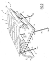
  • la Fig. 2 est une vue schématique en perspective des différents éléments composant la partie arrière du véhicule automobile selon l'invention,
  • les Figs. 3 à 6 sont des vues schématiques en coupe longitudinale de la partie arrière dans les différentes possibilités de transformation du véhicule automobile selon l'invention,
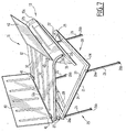
  • la Fig. 7 est une vue schématique en perspective d'une variante des différents éléments composant la partie arrière du véhicule automobile selon l'invention,
  • les Figs. 8 et 9 sont des vues schématiques en coupe longitudinale de la partie arrière dans les différentes possibilités de transformation selon le second mode de réalisation.
Le véhicule automobile représenté sur les figures et désigné dans son ensemble par la référence 1, comporte, de manière classique, une carrosserie formant, entre autres, un habitacle 2 et un coffre 3.
Dans l'exemple de réalisation représenté sur les figures, le véhicule automobile 1 est un véhicule de type coupé, muni de deux portes. Le véhicule automobile selon l'invention peut également être un véhicule automobile de type berline.
De manière classique, l'habitacle 2 est délimité par deux parois latérales 4, un pavillon 5 et un plancher 6 et contient une rangée de sièges avant 7 et une rangée de sièges arrière 8 qui peuvent être déplaçables entre une position d'utilisation et une position escamotée. L'habitacle 2 est également délimité, à sa partie arrière par une lunette arrière 9.
Le coffre 3 est délimité par une cloison 10 de séparation entre l'habitacle 2 et le coffre 3, un ensemble 11 formé par un couvercle 12 et une paroi d'extrémité arrière 13 ainsi que par les deux parois latérales qui se prolongent jusqu'à ladite paroi d'extrémité arrière 13.
La cloison 10 de séparation peut être constituée d'au moins deux éléments articulés entre eux, comme représentés sur les Figs. 1 à 6 ou d'au moins deux éléments déployables par coulissement les uns par rapport aux autres.
Comme représenté à la Fig. 2, l'ensemble 11 formé par le couvercle 12 et la paroi d'extrémité arrière 13 est supporté par un cadre 20 qui comporte deux montants longitudinaux, respectivement 21 et 22, s'étendant parallèlement l'un par rapport à l'autre et par deux montants transversaux, respectivement 23 et 24, s'étendant parallèlement l'un par rapport à l'autre.
Comme on le verra ultérieurement, le cadre 20 est déplaçable, au moyen d'un système d'articulations désigné par la référence générale 25, vers l'arrière du véhicule automobile 1 entre une position haute dans laquelle le couvercle 12 et la paroi d'extrémité arrière 13 ferment le coffre 3 et une position basse dans laquelle ledit couvercle 12 est appliqué contre le plancher 6 pour transformer ce véhicule 1 en véhicule à benne ouverte vers le haut.
Le système d'articulations 25 est formé par deux paires de biellettes parallèles et symétriques l'une par rapport à l'autre.
En se reportant à la Fig. 2, on va décrire une paire de biellettes disposées entre le montant longitudinal 21 et le plancher 6, l'autre paire de biellettes disposées entre le montant longitudinal 22 et le plancher 6 étant identiques.
Chaque paire de biellettes comporte deux biellettes 26 parallèles l'une par rapport à l'autre et chaque biellette 26 comporte une première extrémité 26a montée articulée sur le montant longitudinal 21 correspondant et une seconde extrémité 26b montée articulée sur le plancher 6.
Ainsi, chaque paire de biellettes 26 forme avec le montant longitudinal 21 ou 22 correspondant et le plancher 6 un parallélogramme articulé permettant au cadre 20 supportant l'ensemble 11 formé par le couvercle 12 et la paroi d'extrémité arrière 13 de se déplacer entre la position haute et la position basse s'étendant parallèlement par rapport à ladite position haute.
De plus, l'ensemble 11 formé par le couvercle 12 et la paroi d'extrémité arrière 13 est monté articulé sur le bord transversal avant 23 du cadre 20, par exemple au moyen d'au moins une charnière 27. De ce fait, cet ensemble 11 est déplaçable entre une position de fermeture du coffre 3 et une position d'ouverture dudit coffre 3. Le mouvement d'ouverture de l'ensemble 11 est assisté par deux vérins 28. La cloison 10 de séparation est montée articulée sur le plancher 6 à l'aide d'au moins une charnière 29 si bien que cette cloison 9 est déplaçable par pivotement vers l'arrière du véhicule automobile, ainsi que cela sera décrit ultérieurement, entre une position sensiblement verticale de séparation de l'habitacle 2 et du coffre 3 et une position sensiblement horizontale appliquée contre ledit plancher 6 dans la configuration à benne ouverte vers le haut du véhicule automobile 1.
La paroi d'extrémité arrière 13 est formée par un premier bandeau 13a solidaire du couvercle 12 et par un second bandeau 13b monté articulé au moyen d'au moins une charnière 30 sur ce premier bandeau 13a.
Le second bandeau 13b est donc déplaçable entre une position active prolongeant le premier bandeau 13a dans la position haute du cadre 20 pour fermer le coffre 3 et une position escamotée contre le premier bandeau 13a dans la position basse dudit cadre 20 de façon à éviter que ce second bandeau 13b touche le sol.
Le déplacement du bandeau 13b entre les deux positions est commandé par exemple par des vérins 31 électriques. Enfin, la surface externe du couvercle 11 est pourvue de barres de protection longitudinales 32.
Les différents éléments pivotants, c'est à dire la cloison 10 de séparation, l'ensemble 11 et le cadre 20 sont équipés de moyens de verrouillage ou de maintien dans les différentes positions qu'ils peuvent occuper.
Un joint d'étanchéité 33 assure l'étanchéité entre le couvercle 11 et les montants du cadre 20 et un joint d'étanchéité 34 assure l'étanchéité entre les montants de cadre 20 et notamment les parois latérales 4 et la cloison 10 de séparation.
Dans la configuration initiale représentée sur les Figs. 1 et 3, la plaque 10 est en position sensiblement verticale et assure la séparation entre l'habitacle 2 et le coffre 3 tandis que le cadre 20 est en position haute et le coffre 3 est fermé par l'ensemble 11 constitué par le couvercle 12 et la paroi d'extrémité arrière 13.
Pour charger le coffre 3 du véhicule automobile 1, l'utilisateur actionne une poignée de commande du coffre et l'ensemble 11 s'ouvre en pivotant vers le haut autour des charnières 27, assisté par les deux vérins 28. Le cadre 20 reste immobile en position haute, ainsi que représenté à la Fig. 4. L'utilisateur pose son chargement dans le coffre 3 et referme le couvercle 12 et la paroi d'extrémité arrière 13.
Pour passer de cette configuration à la configuration de type à benne ouverte vers le haut pour permettre à l'utilisateur de charger un objet encombrant, il procède de la façon suivante.
Tout d'abord, l'utilisateur actionne une poignée du cadre et tire ce cadre 20 supportant l'ensemble 11 constitué par le couvercle 12 et la paroi d'extrémité arrière 13, vers l'arrière du véhicule automobile. Le cadre pivote et descend par l'intermédiaire des paires de biellettes 26, comme représenté à la Fig. 5. La position des extrémités 26a et 26b des biellettes 26 permet de faire ressortir plus ou moins vers l'arrière du véhicule automobile, le couvercle 12, ainsi que montré à la Fig. 6. Dans cette position, le bandeau 13b de la paroi d'extrémité arrière 13 est rabattue contre le bandeau fixe 13a par l'intermédiaire des vérins 31 si nécessaire pour éviter qu'il frotte sur le sol.
De plus, la cloison 10 est rabattue vers l'arrière dans le prolongement du couvercle 12 afin de former une surface continue de chargement.
Cette configuration permet à l'utilisateur de transporter des objets très volumineux en hauteur et en longueur.
Sur les Figs. 7 à 9, on a représenté une variante, les éléments communs au précédent mode de réalisation ont été désignés par les mêmes références.
Dans cette variante, le couvercle 12 comporte sur son bord transversal avant 12a, un volet 40 pivotant autour d'au moins une charnière 41 entre une première position appliquée sur le couvercle 12 dans la position haute du cadre 20 (Fig. 8) et une seconde position en prolongement dudit couvercle (12) et appliquée contre le plancher 6 dans la position basse dudit cadre 20 (Fig. 9).
De plus, le couvercle 12 comporte, sur son bord transversal arrière 12b, un volet 42 pivotant autour d'au moins une charnière 43 entre une position horizontale appliquée sur le couvercle 12 (Fig. 8) et une position sensiblement verticale pour constituer un arrêt des charges posées sur ledit couvercle 12 (Fig. 9).
Dans la position haute du cadre 20, c'est à dire dans la position de fermeture du coffre 3 par le couvercle 12 et par la paroi d'extrémité arrière 13, les volets 40 et 42 sont rabattus sur le couvercle 12, comme représenté sur la Fig. 8.
Dans la position basse du cadre 20, correspondant à la configuration à benne ouverte vers le haut du véhicule automobile, le volet 40 est rabattu vers l'avant du véhicule automobile contre le plancher 6 pour constituer une surface de chargement continu avec le couvercle 12 et le volet 42 est placé en position sensiblement verticale de façon à former un arrêt pour les charges placées sur ledit couvercle 12, comme montré à la Fig. 9.
Le véhicule automobile selon l'invention permet de passer facilement d'une configuration de type berline ou de type coupé à une configuration de type à benne ouverte vers le haut au moyen de mécanismes simples à mettre en oeuvre et qui n'empiètent pas sur le volume de chargement disponible, tout en conservant une ouverture traditionnelle du coffre.
Le véhicule automobile selon l'invention peut donc servir aussi bien pour le transport de passagers ou de charges dans un habitacle entièrement fermé, que pour le transport de charges dans une benne ouverte vers le haut et facilement accessible par l'arrière.

Claims (8)

  1. Véhicule automobile transformable en véhicule automobile à benne ouverte vers le haut appelé pick-up, du type comportant, d'une part, un habitacle (2) délimité par deux parois latérales (4), un pavillon (5) et un plancher (6) et contenant au moins une rangée de sièges (7, 8) et, d'autre part, un coffre (3) délimité par une cloison (10) de séparation entre l'habitacle (2) et le coffre (3) et par au moins un ensemble (11) formé par un couvercle (12) et une paroi d'extrémité arrière (13) solidaire dudit couvercle (12), caractérisé en ce que l'ensemble (11) formé par le couvercle (12) et la paroi d'extrémité (13) est supporté par un cadre (20) déplaçable au moyen d'un système d'articulations (25) vers l'arrière du véhicule entre une position haute dans laquelle le couvercle (12) et la paroi d'extrémité (13) ferment le coffre (3) et une position basse dans laquelle ledit couvercle (12) est appliqué contre le plancher (6) pour transformer ce véhicule en véhicule à benne ouverte vers le haut.
  2. Véhicule automobile selon la revendication 1, caractérisé en ce que le système d'articulations (25) est formé par deux paires de biellettes (26) parallèles et disposées chacune entre un montant longitudinal (21, 22) du cadre (20) et le plancher (6).
  3. Véhicule automobile selon la revendication 2, caractérisé en ce que chaque biellette (26) comporte une première extrémité (26a) montée articulée sur le montant longitudinal (21, 22) correspondant et une seconde extrémité (26b) montée articulée sur le plancher (6).
  4. Véhicule automobile selon l'une quelconque des revendications 1 à 3, caractérisé en ce que l'ensemble (11) formé par le couvercle (12) et la paroi d'extrémité (13) est monté articulé sur le cadre (20) et déplaçable, dans la position haute dudit cadre (20), entre une position de fermeture du coffre (3) et une position d'ouverture dudit coffre (3).
  5. Véhicule automobile selon l'une quelconque des revendications 1 à 4, caractérisé en ce que la cloison (10) de séparation est montée articulée sur le plancher (6) et est basculable vers l'arrière du véhicule entre une position sensiblement verticale de séparation de l'habitacle (2) et du coffre (3) et une position sensiblement horizontale appliquée contre ledit plancher (6) dans la configuration à benne ouverte vers le haut.
  6. Véhicule automobile selon l'une quelconque des revendications 1 à 5, caractérisé en ce que le couvercle (12) comporte, sur son bord transversal avant (12a), un volet (40) pivotant entre une première position appliquée sur le couvercle (12) dans la position haute du cadre (20) et une seconde position en prolongement dudit couvercle (12) et appliquée contre le plancher (6) dans la position basse dudit cadre (20).
  7. Véhicule automobile selon l'une quelconque des revendications 1 à 6, caractérisé en ce que le couvercle (12) comporte, sur son bord transversal arrière (12b), un volet (42) pivotant entre une position horizontale appliquée sur le couvercle (12) et une position sensiblement verticale.
  8. Véhicule automobile selon l'une quelconque des revendications 1 à 7, caractérisé en ce que la paroi d'extrémité (13) est formée par un premier bandeau (13a) solidaire du couvercle (12) et par un second bandeau (13b) monté articulé sur ce premier bandeau (13a) et déplaçable entre une position active prolongeant ledit premier bandeau (13a) dans la position haute du cadre (20) et une position escamotée contre le premier bandeau (13a) dans la position basse dudit cadre (20).
EP03293017A 2002-12-03 2003-12-02 Véhicule automobile transformable en véhicule à benne ouverte vers le haut Withdrawn EP1426235A1 (fr)

Applications Claiming Priority (2)

Application Number Priority Date Filing Date Title
FR0215228A FR2847863B1 (fr) 2002-12-03 2002-12-03 Vehicule automobile transformable en vehicule a benne ouverte vers le haut.
FR0215228 2002-12-03

Publications (1)

Publication Number Publication Date
EP1426235A1 true EP1426235A1 (fr) 2004-06-09

Family

ID=32309976

Family Applications (1)

Application Number Title Priority Date Filing Date
EP03293017A Withdrawn EP1426235A1 (fr) 2002-12-03 2003-12-02 Véhicule automobile transformable en véhicule à benne ouverte vers le haut

Country Status (2)

Country Link
EP (1) EP1426235A1 (fr)
FR (1) FR2847863B1 (fr)

Cited By (5)

* Cited by examiner, † Cited by third party
Publication number Priority date Publication date Assignee Title
FR2914887A1 (fr) * 2007-04-12 2008-10-17 Peugeot Citroen Automobiles Sa Vehicule automobile tricorps a surface de charge modulable
EP2495132A1 (fr) * 2011-03-03 2012-09-05 Peugeot Citroën Automobiles SA Table escamotable pour véhicule.
FR2985233A1 (fr) * 2012-01-02 2013-07-05 Peugeot Citroen Automobiles Sa Habitacle arriere d'un vehicule automobile avec banquette arriere et element de cloisonnement par rapport au coffre escamotables
RU203010U1 (ru) * 2020-12-18 2021-03-18 Дарья Вячеславовна Овчинникова Платформа-трансформер багажного и пассажирского отделений автомобиля
WO2023187219A1 (fr) * 2022-04-01 2023-10-05 Emil Kaltenbach Gmbh & Co. Kg Véhicule à moteur avec support de charge

Families Citing this family (3)

* Cited by examiner, † Cited by third party
Publication number Priority date Publication date Assignee Title
FR2884482B1 (fr) * 2005-04-14 2007-07-06 Peugeot Citroen Automobiles Sa Vehicule automobile de type berline transformable.
FR2884483B1 (fr) * 2005-04-14 2007-07-06 Peugeot Citroen Automobiles Sa Vehicule automobile transformable.
FR2884484B1 (fr) * 2005-04-14 2007-07-06 Peugeot Citroen Automobiles Sa Vehicule automobile de type berline transformable.

Citations (3)

* Cited by examiner, † Cited by third party
Publication number Priority date Publication date Assignee Title
US1786693A (en) * 1929-08-01 1930-12-30 Blass Wilhelm Transformation of a motor car with closed carriage body into a platform lorry
US5203364A (en) * 1992-03-20 1993-04-20 Arie Koole Canopy jack assembly and method of operation
EP1234754A1 (fr) * 2001-02-26 2002-08-28 Peugeot Citroen Automobiles SA Véhicule automobile de type break transformable en un véhicule à benne ouverte vers le haut

Patent Citations (3)

* Cited by examiner, † Cited by third party
Publication number Priority date Publication date Assignee Title
US1786693A (en) * 1929-08-01 1930-12-30 Blass Wilhelm Transformation of a motor car with closed carriage body into a platform lorry
US5203364A (en) * 1992-03-20 1993-04-20 Arie Koole Canopy jack assembly and method of operation
EP1234754A1 (fr) * 2001-02-26 2002-08-28 Peugeot Citroen Automobiles SA Véhicule automobile de type break transformable en un véhicule à benne ouverte vers le haut

Cited By (6)

* Cited by examiner, † Cited by third party
Publication number Priority date Publication date Assignee Title
FR2914887A1 (fr) * 2007-04-12 2008-10-17 Peugeot Citroen Automobiles Sa Vehicule automobile tricorps a surface de charge modulable
EP2495132A1 (fr) * 2011-03-03 2012-09-05 Peugeot Citroën Automobiles SA Table escamotable pour véhicule.
FR2972157A1 (fr) * 2011-03-03 2012-09-07 Peugeot Citroen Automobiles Sa Table escamotable pour vehicule.
FR2985233A1 (fr) * 2012-01-02 2013-07-05 Peugeot Citroen Automobiles Sa Habitacle arriere d'un vehicule automobile avec banquette arriere et element de cloisonnement par rapport au coffre escamotables
RU203010U1 (ru) * 2020-12-18 2021-03-18 Дарья Вячеславовна Овчинникова Платформа-трансформер багажного и пассажирского отделений автомобиля
WO2023187219A1 (fr) * 2022-04-01 2023-10-05 Emil Kaltenbach Gmbh & Co. Kg Véhicule à moteur avec support de charge

Also Published As

Publication number Publication date
FR2847863A1 (fr) 2004-06-04
FR2847863B1 (fr) 2005-03-04

Similar Documents

Publication Publication Date Title
EP1426235A1 (fr) Véhicule automobile transformable en véhicule à benne ouverte vers le haut
EP1234702B1 (fr) Véhicule automobile de type break transformable en un véhicule à benne ouverte vers le haut
EP1234754B1 (fr) Véhicule automobile de type break transformable en un véhicule à benne ouverte vers le haut
EP1234758B1 (fr) Véhicule automobile de type break transformable en un véhicule à benne ouverte vers le haut
EP1234757B1 (fr) Véhicule automobile de type break transformable en un véhicule à benne ouverte
EP1234703B1 (fr) Véhicule automobile de type break transformable
EP1234756B1 (fr) Véhicule automobile de type break transformable
FR2598362A1 (fr) Vehicule chargeable par l'arriere
EP1234755B1 (fr) Véhicule automobile transformable
EP1868845B1 (fr) Vehicule automobile transformable
FR2746059A1 (fr) Porte laterale de vehicule automobile a cinematique d'ouverture perfectionnee
EP1868844B1 (fr) Vehicule automobile de type berline transformable
EP1369274A1 (fr) Structure de hayon pour véhicule automobile transformable et véhicule automobile équipé d'une telle structure de hayon
FR2862039A1 (fr) Structure de hayon pour vehicule automobile et vehicule automobile equipe d'une telle structure de hayon
FR3085902A1 (fr) Vehicule tricorps convertissable en pick-up comprenant un volet de fermeture de coffre multifonction
EP1868873B1 (fr) Vehicule automobile de type berline transformable
FR2847864A1 (fr) Vehicule automobile de type berline transformable
FR2825062A1 (fr) Vehicule automobile de type break transformable
EP1806255B1 (fr) Ensemble de support d'un panneau de coffre de véhicule automobile et véhicule automobile équipé d'un tel ensemble de support
FR2909317A1 (fr) Structure de hayon pour vehicule automobile transformable et vehicule automobile equipe d'une telle structure de hayon
FR2910428A1 (fr) Vehicule automobile du type berline transformable en un vehicule du type a benne ouverte vers le haut
EP1588896A1 (fr) Tablette arrière de véhicule automobile.
FR2821304A1 (fr) Vehicule automobile de type break transformable
FR2885325A1 (fr) Vehicule du type cabriolet a toit rigide type targa
FR2885326A1 (fr) Vehicule du type cabriolet a toit rigide avec cloison fixe

Legal Events

Date Code Title Description
PUAI Public reference made under article 153(3) epc to a published international application that has entered the european phase

Free format text: ORIGINAL CODE: 0009012

AK Designated contracting states

Kind code of ref document: A1

Designated state(s): AT BE BG CH CY CZ DE DK EE ES FI FR GB GR HU IE IT LI LU MC NL PT RO SE SI SK TR

AX Request for extension of the european patent

Extension state: AL LT LV MK

17P Request for examination filed

Effective date: 20041113

AKX Designation fees paid

Designated state(s): AT BE BG CH CY CZ DE DK EE ES FI FR GB GR HU IE IT LI LU MC NL PT RO SE SI SK TR

17Q First examination report despatched

Effective date: 20050201

GRAP Despatch of communication of intention to grant a patent

Free format text: ORIGINAL CODE: EPIDOSNIGR1

STAA Information on the status of an ep patent application or granted ep patent

Free format text: STATUS: THE APPLICATION IS DEEMED TO BE WITHDRAWN

18D Application deemed to be withdrawn

Effective date: 20080808