EP1426127A1 - Schneidwerkzeug, insbesondere zur Bearbeitung von Kolbenringen - Google Patents
Schneidwerkzeug, insbesondere zur Bearbeitung von Kolbenringen Download PDFInfo
- Publication number
- EP1426127A1 EP1426127A1 EP03018900A EP03018900A EP1426127A1 EP 1426127 A1 EP1426127 A1 EP 1426127A1 EP 03018900 A EP03018900 A EP 03018900A EP 03018900 A EP03018900 A EP 03018900A EP 1426127 A1 EP1426127 A1 EP 1426127A1
- Authority
- EP
- European Patent Office
- Prior art keywords
- cutting
- edge
- tool according
- cutting tool
- section
- Prior art date
- Legal status (The legal status is an assumption and is not a legal conclusion. Google has not performed a legal analysis and makes no representation as to the accuracy of the status listed.)
- Granted
Links
- 238000005520 cutting process Methods 0.000 title claims abstract description 114
- 210000000078 claw Anatomy 0.000 claims description 12
- 230000001154 acute effect Effects 0.000 claims description 5
- 238000004519 manufacturing process Methods 0.000 description 10
- 238000003754 machining Methods 0.000 description 5
- 238000003801 milling Methods 0.000 description 4
- 239000000463 material Substances 0.000 description 3
- 238000000227 grinding Methods 0.000 description 2
- 230000015572 biosynthetic process Effects 0.000 description 1
- 238000002485 combustion reaction Methods 0.000 description 1
- 230000000295 complement effect Effects 0.000 description 1
- 238000005553 drilling Methods 0.000 description 1
- 238000002955 isolation Methods 0.000 description 1
- 238000000034 method Methods 0.000 description 1
- 230000002028 premature Effects 0.000 description 1
- 238000004321 preservation Methods 0.000 description 1
- 230000002441 reversible effect Effects 0.000 description 1
- 239000004576 sand Substances 0.000 description 1
- 238000000926 separation method Methods 0.000 description 1
- 230000007704 transition Effects 0.000 description 1
- 239000002699 waste material Substances 0.000 description 1
Images

Classifications
-
- B—PERFORMING OPERATIONS; TRANSPORTING
- B23—MACHINE TOOLS; METAL-WORKING NOT OTHERWISE PROVIDED FOR
- B23B—TURNING; BORING
- B23B27/00—Tools for turning or boring machines; Tools of a similar kind in general; Accessories therefor
- B23B27/14—Cutting tools of which the bits or tips or cutting inserts are of special material
- B23B27/16—Cutting tools of which the bits or tips or cutting inserts are of special material with exchangeable cutting bits or cutting inserts, e.g. able to be clamped
- B23B27/1644—Cutting tools of which the bits or tips or cutting inserts are of special material with exchangeable cutting bits or cutting inserts, e.g. able to be clamped with plate-like cutting inserts of special shape clamped by a clamping member acting almost perpendicularly on the chip-forming plane and at the same time upon the wall of a hole in the cutting insert
- B23B27/1651—Cutting tools of which the bits or tips or cutting inserts are of special material with exchangeable cutting bits or cutting inserts, e.g. able to be clamped with plate-like cutting inserts of special shape clamped by a clamping member acting almost perpendicularly on the chip-forming plane and at the same time upon the wall of a hole in the cutting insert characterised by having a special shape
-
- B—PERFORMING OPERATIONS; TRANSPORTING
- B23—MACHINE TOOLS; METAL-WORKING NOT OTHERWISE PROVIDED FOR
- B23B—TURNING; BORING
- B23B27/00—Tools for turning or boring machines; Tools of a similar kind in general; Accessories therefor
- B23B27/06—Profile cutting tools, i.e. forming-tools
-
- Y—GENERAL TAGGING OF NEW TECHNOLOGICAL DEVELOPMENTS; GENERAL TAGGING OF CROSS-SECTIONAL TECHNOLOGIES SPANNING OVER SEVERAL SECTIONS OF THE IPC; TECHNICAL SUBJECTS COVERED BY FORMER USPC CROSS-REFERENCE ART COLLECTIONS [XRACs] AND DIGESTS
- Y10—TECHNICAL SUBJECTS COVERED BY FORMER USPC
- Y10T—TECHNICAL SUBJECTS COVERED BY FORMER US CLASSIFICATION
- Y10T407/00—Cutters, for shaping
- Y10T407/22—Cutters, for shaping including holder having seat for inserted tool
- Y10T407/2202—Plural spaced seats and common holder
-
- Y—GENERAL TAGGING OF NEW TECHNOLOGICAL DEVELOPMENTS; GENERAL TAGGING OF CROSS-SECTIONAL TECHNOLOGIES SPANNING OVER SEVERAL SECTIONS OF THE IPC; TECHNICAL SUBJECTS COVERED BY FORMER USPC CROSS-REFERENCE ART COLLECTIONS [XRACs] AND DIGESTS
- Y10—TECHNICAL SUBJECTS COVERED BY FORMER USPC
- Y10T—TECHNICAL SUBJECTS COVERED BY FORMER US CLASSIFICATION
- Y10T407/00—Cutters, for shaping
- Y10T407/22—Cutters, for shaping including holder having seat for inserted tool
- Y10T407/2202—Plural spaced seats and common holder
- Y10T407/2206—Simultaneously usable
-
- Y—GENERAL TAGGING OF NEW TECHNOLOGICAL DEVELOPMENTS; GENERAL TAGGING OF CROSS-SECTIONAL TECHNOLOGIES SPANNING OVER SEVERAL SECTIONS OF THE IPC; TECHNICAL SUBJECTS COVERED BY FORMER USPC CROSS-REFERENCE ART COLLECTIONS [XRACs] AND DIGESTS
- Y10—TECHNICAL SUBJECTS COVERED BY FORMER USPC
- Y10T—TECHNICAL SUBJECTS COVERED BY FORMER US CLASSIFICATION
- Y10T407/00—Cutters, for shaping
- Y10T407/22—Cutters, for shaping including holder having seat for inserted tool
- Y10T407/2208—Plural simultaneously usable separable tools in common seat or common clamp actuator for plural simultaneously usable tools
-
- Y—GENERAL TAGGING OF NEW TECHNOLOGICAL DEVELOPMENTS; GENERAL TAGGING OF CROSS-SECTIONAL TECHNOLOGIES SPANNING OVER SEVERAL SECTIONS OF THE IPC; TECHNICAL SUBJECTS COVERED BY FORMER USPC CROSS-REFERENCE ART COLLECTIONS [XRACs] AND DIGESTS
- Y10—TECHNICAL SUBJECTS COVERED BY FORMER USPC
- Y10T—TECHNICAL SUBJECTS COVERED BY FORMER US CLASSIFICATION
- Y10T407/00—Cutters, for shaping
- Y10T407/22—Cutters, for shaping including holder having seat for inserted tool
- Y10T407/2272—Cutters, for shaping including holder having seat for inserted tool with separate means to fasten tool to holder
- Y10T407/2274—Apertured tool
-
- Y—GENERAL TAGGING OF NEW TECHNOLOGICAL DEVELOPMENTS; GENERAL TAGGING OF CROSS-SECTIONAL TECHNOLOGIES SPANNING OVER SEVERAL SECTIONS OF THE IPC; TECHNICAL SUBJECTS COVERED BY FORMER USPC CROSS-REFERENCE ART COLLECTIONS [XRACs] AND DIGESTS
- Y10—TECHNICAL SUBJECTS COVERED BY FORMER USPC
- Y10T—TECHNICAL SUBJECTS COVERED BY FORMER US CLASSIFICATION
- Y10T82/00—Turning
- Y10T82/10—Process of turning
Definitions
- the invention relates to a cutting tool, which in particular for Machining a piston ring is provided.
- Piston rings are mass-produced in internal combustion engines, e.g. B. in the automotive industry used.
- the manufacture of piston rings usually is carried out by means of machining processes, in particular in this respect complicated, as piston rings generally on the outer circumference have a finely structured surface.
- conventional piston rings are often included provided an annular centering or spacing web, the with respect to the Piston ring axis axial expansion is only a few millimeters.
- Such a fine outer contour is often characterized by an axial with respect to the piston ring as well as radial movement of the cutting tool along the circumference of the piston ring generated.
- such a method is comparatively time-consuming and therefore only of limited suitability for mass production.
- a piston ring is the cutting tool in the axial direction on the circumference introduced to a raw form and initially cuts only a semi-contour an end face of the raw form. A second is needed to complete the piston ring Processing step required, in the course of which processing the second Front of the raw form is done.
- From EP 1 033 210 A2 and DE 298 04 413 U1 are also particularly for Milling tools provided cutting plates disclosed. From EP 1 033 210 A2 it is known to provide a cutting edge in a one-piece insert, which has a curved or stepped contour. The making of such However, the insert is comparatively complex, especially if the Contour have a fine structure, especially edges and incisions should. From DE 298 04 413 U1 is the use of two, over the scope a common milling head distributed cutting plates for milling one Known surface contour of a workpiece. Doing so from each insert when the milling head rotates, a half-contour of the workpiece worked out.
- the invention has for its object to provide a cutting tool which for producing a fine outer contour, in particular a piston ring, is particularly suitable.
- a cutting tool which for producing a fine outer contour, in particular a piston ring, is particularly suitable.
- the manufacture and the ongoing operation of the cutting tool to be inexpensive.
- the cutting tool comprises a cutting plate with one whose front edge arranged first main cutting edge, in which an approximately U-shaped Incision is sunk.
- the side legs of the incision form one secondary cutting edge each.
- the bottom of the incision forms one in the feed direction second main cutting edge set back behind the first main cutting edge.
- the insert includes at least two disjointed ones Sections, each of which is a part of the incision, and thus the associated Cutting edges, carries.
- the basic idea of the invention is that the production of the outer contour is significantly simplified by a tool that the outer contour along a radial feed path with respect to the workpiece axis in one Cut out operation.
- This simplified manufacturing process is made possible through a cutting plate with a fine incision.
- the manufacture of such an insert is very complicated, especially since it is inside of the incision edges of the cutting plate not or only difficult to access for grinding tools, and therefore the application of the Cutting edges are hindered. Trouble-free manufacture of the insert On the other hand, it is recognized that this is possible if the cutting insert is made in several parts and the dividing line between adjacent sections of the insert in Area of the incision.
- each section of the Cutting plate can be ground separately, with unhindered access to the Grinding tool is secured to each cutting edge.
- the one for producing the fine The incision required for the outer contour is therefore only made after the two have been placed against one another of the individual sections.
- first main cutting edge and the adjacent one Side legs of the incision formed an acute angle so that the clear width of the incision towards the center of the panel and thus against the intended Feed direction, widened. This ensures adequate Clearance for the secondary cutting edges arranged on the side legs.
- the first main cutting edge preferably forms a straight line.
- the second main cutting edge parallel to the first main cutting edge runs. This shape is particularly useful for production a conventional piston ring, on the outer circumference of a cross section rectangular centering and spacing web is provided. If necessary, you can equivalently the first and / or the second main cutting edge obliquely be oriented to the feed direction.
- a curved first and / or second main cutting edge also produces curved outer contours become.
- a parallel offset arrangement of the front edges of the two sections conceivable.
- the side edges of each section are in relation to one another parallel.
- the side edges of a single section as well as the side edges of different Parts are always at the same angle to the intended Feed direction and can therefore be used as a contact surface on a tool holder and also used as a contact surface between adjacent sections become.
- the side edges are preferably oblique with respect to the feed direction oriented.
- Through a trailing edge that is approximately perpendicular to the feed direction each section is a particularly simple adjustment of the section achieved a tool holder.
- the rear edge serves as a stable, flat surface Stop to compensate for the feed from the workpiece to the Partial forces exerted.
- the side edges and the rear edge however, be shaped arbitrarily. For the partial preservation of the described The only advantage is to ensure that the sections are flush with each other as well can be placed on corresponding contact surfaces of the tool holder.
- the insert is made in two parts, the dividing line runs between the two sections such that a section one Side leg of the incision bears while the second section bears the floor as well as the other side leg.
- the advantage of this version is in particular in that the two sections in one of the cutting process corner points of the U-shaped incision hardly mechanically stressed on each other bump, and thus premature wear of the cut edges at the joint is prevented. Furthermore, the cutting edges are in this version particularly easy to sand.
- An embodiment of the invention in which the sections are particularly advantageous are of identical design and are therefore congruent in terms of area in particular.
- both side edges of each section are with an ausoder Provide bleed to cut or bleed each other Side edge forms complementary part of the U-shaped incision.
- the identical execution of the sections simplifies production the insert and its use, especially since only a single form of Parts must be manufactured or kept in stock.
- Another big one The advantage is that the sections are swapped like a reversible insert can, the cutting edges previously located on the side of the Cutting plate again an identical U-shaped incision with new, unused Form cutting edges.
- a similar advantage is provided by a Part of the point-symmetrical design of the section achieved. To this In this way, two diagonally opposite corner points of each section bear the same cutting edge arrangement, so that with a 180 ° rotation around the center of the surface a used cutting edge in the manner of an insert an identical, new cutting edge can be replaced.
- a tool holder that is particularly suitable for the cutting insert according to the invention includes a bearing surface for the cutting plate and a rear and a side stop, which with the rear edge of the insert or with a side edge of the insert cooperate.
- the invention Tool holder allows easy assembly of the insert pieces at the same time high stability.
- the insert pieces are either through Screws fixed to the tool holder, but preferably by means of a clamp.
- the sections of the cutting insert are thereby caused by the claw tension advantageously acted against the stops of the tool holder and thus automatically adjusted.
- the or each claw is expediently such arranged that they have unused cutting edges of the respective insert piece covered and thus against damage from machined material protects.
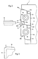
- the cutting tool 1 shown in FIG. 1 comprises a tool holder 2 and an insert 3 mounted thereon.
- the insert 3 is composed of two identical sections 4a, 4b, each with an approximately parallelogram-like base educated.
- the sections 4a, 4b lie on one in the intended direction of advance V seen, gradation introduced into the tool holder 2 on the front 5, so that each section 4a, 4b with a tool holder 2 facing The rear edge 6a, 6b abuts the rear wall 7 of the gradation 5.
- the back wall 7 thus forms a rear stop for the sections 4a, 4b.
- the gradation 5 is to a transverse end 8 of the tool holder 2 through a holding projection 9 limited, the inner wall 10 a lateral stop for the section 4a forms.
- the inner wall 10 takes a blunt with the rear wall 7 Angle that corresponds to the obtuse parallelogram angle of the parallelogram Part 4a corresponds.
- a side edge 11a of the section lies 4a flat on the inner wall 10.
- One in the area of the intersection between the Inner wall 10 and rear wall 7 recess made in the tool holder 2 12 improves the placement of the section 4a on the inner wall 10 and Rear wall 7.
- the side edge 13a opposite the side edge 11a serves as a contact surface for the adjacent side edge 11b of the second section 4b, which also lies in gradation 5, offset parallel to the first section 4a.
- the two, the respective rear edge 6a, 6b of the respective section 4a or 4b opposite front edges 14a and 14b are aligned and form together a first main cutting edge oriented approximately perpendicular to the feed direction V. 15 for machining a workpiece 16.
- the main cutting edge 15 is at least in contact with the workpiece 16 Part area with a bevel 17.
- the first main cutting edge 15 In the joint area between the sections 4a and 4b is the first main cutting edge 15 through an incision 18 interrupted, which has approximately the shape of a square letter "U".
- the incision 18 includes two side legs 19 and 20, the first Main cutting edge 15 under a point slightly below 90 ° Angled against the feed direction V and to form Secondary cutting edges are ground.
- the incision 18 further comprises a connecting the two side legs 19 and 20 to the first main cutting edge 15 parallel bottom 21, one opposite the first main cutting edge 15 set back in the feed direction V second main cutting edge 22 forms and is also ground for this purpose.
- the incision 18 is arranged with respect to the sections 4a and 4b in such a way that the section 4a carries the side leg 19 and the bottom 21, while the Section 4b carries the second side leg 20. In other words, it runs Separation line between the two sections 4a and 4b such that they are exactly in the Transition between the side leg 20 and the bottom 21 on the incision 18 bumps.
- the section 4a is between the side edge 13a and the front edge 14a formed corner area with an acute angle Provide cutout 23a, the ground leg of the side leg 19 and form the bottom 21.
- section 4b bears on the latter Side edge 11 legs ground and at an obtuse angle from the Side edge 11b angled gate 24b, which forms the side leg 20.
- the section is also 4a provided on its side edge 11a with a corresponding gate 24a.
- the section 4b carries an acute angle at its side edge 13b Section 23b. If parts 4a and 4b are interchanged, e.g. B. after wear in the area of the cutout 23a and the cut 24b Cutting edges, the cutting plate 3 shown in Fig. 1 is identical reproduced. However, the incision 18 through the cutout 23b and the gate 24a formed.
- the sections 4a and 4b are thus after Principle of an indexable insert can be used several times. It is also possible in a manner not shown in more detail identical to the sections 4a and 4b To create sections on section 4b, so that several, to the incision 18 identical incisions would be arranged side by side.
- Each section is for fastening the sections 4a and 4b to the tool holder 2 4a, 4b with a parallelogram-like with respect to the center of the surface 25a, 25b Basic shape of the respective section 4a, 4b centered bore 26a, 26b provided by which the section 4a, 4b in a manner not shown on Tool holder 2 can be screwed on.
- FIG. 2 shows an alternative embodiment of the cutting tool 1, which differs from that shown in FIG. 1 by the shape of the sections 4a and 4b Execution differs.
- the again identical sections 4a and 4b are here with additional bevels arranged on the rear edge 6a, 6b 30 provided.
- the section 4a is thus provided with a cutout 23a ', which relates to of the center point 25a is point-symmetrical to the cutout 23a.
- the section 4a likewise bears a cut to the gate 24a with respect to the center of the surface 25a point-symmetrical gate 24a '.
- the section 4a is thereby point symmetrical in itself. The same applies to the section 4b.
- the shape improves the material utilization of the sections 4a and 4b reached, especially since each section 4a and 4b by a 180 ° rotation the center of the surface 25a or 25b in a position identical to the starting position passes over, and thus there are four identical possible combinations of the sections 4a and 4b with a different cutting edge arrangement in the incision 18 there.
- FIG. 3 is an enlarged detail view of the between the first main cutting edge 15 and the side leg 20 formed corner area.
- the corner region 31 is rounded to the formation to avoid a sharp edge on the finished workpiece 16.
- An identical one Rounding also has between the first main cutting edge 15 and the Side leg 19 formed corner area.
- the corner area 31 also a so-called chamfer, i.e. one with respect to the main cutting edge 15 wear a bevel that takes up a 45 ° angle.
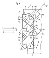
- FIG. 4 differs from the embodiment shown in Fig. 2 in that instead the screw fixing the sections 4a and 4b by a clamping claw 32a and 32b are fixed on the tool holder 2.
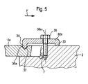
- Each claw 32a, 32b is, as in particular also emerges from the cross section shown in FIG. 5, with a Support web 33 supported on the tool holder 2 and on the other hand engages with one Holding web 34 in an approximately V-shaped groove 35a, 35b of the corresponding section 4a, 4b.
- Each claw 32a, 32b is by a screw 36a, 36b acted against the tool holder 2 and thus holds the section 4a, 4b on Tool holder 2.
- the section 4a, 4b is not only in the direction of Screw axis 38, but also perpendicular to it in the longitudinal direction of the Clamping claw 32a, 32b applied directed force F.
- the clamping claws 32a, 32b diagonally are arranged with respect to the tool holder 2 and thus both to the Rear wall 7 as well as to the inner wall 10 or the side edge 13a in approximately the same Stand angle.
- the sections 4a and 4b are then when tightening the Screws 38a, 38b are pressed by the force F against the corresponding stops and thereby automatically adjusted.
- the clamping claws 32a, 32b are also arranged so that they cut and cut unused for cutting Cover 23a ', 24a', 23b 'and 24b and thus against damage from Protect chip waste.
- the front edges 14a, 14b are ground over their entire length.
- the trailing edges 6a, 6b is in this embodiment under one, the angle corresponding to the clearance angle of the bevel.
Landscapes
- Engineering & Computer Science (AREA)
- Mechanical Engineering (AREA)
- Cutting Tools, Boring Holders, And Turrets (AREA)
- Pistons, Piston Rings, And Cylinders (AREA)
- Auxiliary Devices For Machine Tools (AREA)
- Scissors And Nippers (AREA)
- Milling Processes (AREA)
Abstract
Description
- Fig. 1
- in Draufsicht ein Schneidwerkzeug mit einem Werkzeughalter und einer zweiteilig ausgeführten Schneidplatte sowie ein bearbeitetes Werkstück, insbesondere einen Kolbenring,
- Fig. 2
- in einer Darstellung gemäß Fig. 1 eine alternative Ausführungsform des Schneidwerkzeugs,
- Fig. 3
- in vergrößerter Darstellung eine Detailansicht III gemäß Fig. 2,
- Fig. 4
- in einer Darstellung gemäß Fig. 1 eine weitere Ausführungsform des Schneidwerkzeugs und
- Fig. 5
- in einem Querschnitt V-V das Schneidwerkzeug gemäß Fig. 4.
- 1
- Schneidwerkzeug
- 2
- Werkzeughalter
- 3
- Schneidplatte
- 4
- Teilstück
- 5
- Abstufung
- 6
- Hinterkante
- 7
- Rückwand
- 8
- Querende
- 9
- Haltevorsprung
- 10
- Innenwand
- 11
- Seitenkante
- 12
- Ausnehmung
- 13
- Seitenkante
- 14
- Frontkante
- 15
- Hauptschneidkante
- 16
- Werkstück
- 17
- Anschliff
- 18
- Einschnitt
- 19,20
- Seitenschenkel
- 21
- Boden
- 22
- Hauptschneidkante
- 23
- Ausschnitt
- 24
- Anschnitt
- 25
- Flächenmittelpunkt
- 26
- Bohrung
- 27
- Rohform
- 28
- Umfang
- 29
- Ringachse
- 30
- Anschliff
- 31
- Eckbereich
- 32
- Klemmpratze
- 33
- Stützsteg
- 34
- Haltesteg
- 35
- Nut
- 36
- Schraube
- 37
- Wand
- 38
- Schraubenachse
- V
- Vorschubrichtung
- F
- Kraft
Claims (14)
- Schneidwerkzeug (1) mit einer Schneidplatte (3), an deren Frontkante (14) eine erste Hauptschneidkante (15) und ein diese unterbrechender, etwa U-förmiger Einschnitt (18) angeordnet ist, wobei die Seitenschenkel (19, 20) des Einschnitts (18) jeweils eine Nebenschneidkante, und der Boden (21) des Einschnitts (18) eine in Vorschubrichtung (V) hinter die erste Hauptschneidkante (15) zurückversetzte zweite Hauptschneidkante (22) bilden, und wobei die Schneidplatte (3) aus mindestens zwei getrennten Teilstükken (4a,4b) gebildet ist, von denen jedes einen Teil des Einschnitts (18) trägt.
- Schneidwerkzeug nach Anspruch 1,
dadurch gekennzeichnet, dass die erste Hauptschneidkante (15) mit dem jeweils angrenzenden Seitenschenkel (19, 20) einen spitzen Winkel bildet. - Schneidwerkzeug nach einem der Ansprüche 1 oder 2,
dadurch gekennzeichnet, dass die erste Hauptschneidkante (15) eine gerade, senkrecht zur Vorschubrichtung (V) orientierte Linie bildet. - Schneidwerkzeug nach einem der Ansprüche 1 bis 3,
dadurch gekennzeichnet, dass die zweite Hauptschneidkante (22) etwa parallel zur ersten Hauptschneidkante (15) verläuft. - Schneidwerkzeug nach einem der Ansprüche 1 bis 4,
dadurch gekennzeichnet, dass jedes Teilstück (4) parallele Seitenkanten (11, 13) aufweist. - Schneidwerkzeug nach Anspruch 5,
dadurch gekennzeichnet, dass die Seitenkanten (11, 13) unter spitzem Winkel bezüglich der Vorschubrichtung (V) ausgerichtet sind. - Schneidwerkzeug nach einem der Ansprüche 1 bis 6,
dadurch gekennzeichnet, dass jedes Teilstück (4) eine zur Vorschubrichtung (V) etwa senkrechte Hinterkante (6) aufweist. - Schneidwerkzeug nach einem der Ansprüche 1 bis 7,
dadurch gekennzeichnet, dass ein erstes Teilstück (4b) einen Seitenschenkel (20) des Einschnitts (18) trägt, und dass ein zweites Teilstück (4a) den Boden (21) sowie den anderen Seitenschenkel (19) des Einschnitts (18) trägt. - Schneidwerkzeug nach einem der Ansprüche 1 bis 8,
dadurch gekennzeichnet, dass die Teilstücke (4a, 4b) identisch ausgebildet sind. - Schneidwerkzeug nach einem der Ansprüche 1 bis 9,
gekennzeichnet durch mindestens ein Teilstück (4) mit einer bezüglich seines Flächenmittelpunkts (25) punktsymmetrischen Grundfläche. - Schneidwerkzeug nach einem der Ansprüche 1 bis 10,
gekennzeichnet durch einen Werkzeughalter (2), der eine Auflagefläche (5) für die Schneidplatte (3), einen mit der Hinterkante (6) der Schneidplatte (3) zusammenwirkenden rückwärtigen Anschlag (7) sowie einen mit einer Seitenkante (11a) der Schneidplatte (3) zusammenwirkenden seitlichen Anschlag (10) umfasst. - Schneidwerkzeug nach einem der Ansprüche 1 bis 11,
dadurch gekennzeichnet, dass die Schneidplatte (3) mittels einer Schraubfixierung am Werkzeughalter (2) gehalten ist. - Schneidwerkzeug nach einem der Ansprüche 1 bis 11,
dadurch gekennzeichnet, dass die Schneidplatte (3) durch eine Pratzenklemmung am Werkzeughalter (2) gehalten ist. - Schneidwerkzeug nach Anspruch 13,
dadurch gekennzeichnet, dass die oder jede Klemmpratze (32) derart ausgebildet ist, dass unbenutzte Schneidenkanten (23a', 24a', 23b', 23b) der Schneidplatte (3) durch die Klemmpratze (32) abgedeckt sind.
Applications Claiming Priority (4)
| Application Number | Priority Date | Filing Date | Title |
|---|---|---|---|
| DE20214238 | 2002-09-13 | ||
| DE20214238U | 2002-09-13 | ||
| DE20216864U | 2002-11-02 | ||
| DE20216864U DE20216864U1 (de) | 2002-09-13 | 2002-11-02 | Schneidwerkzeug, insbesondere zur Bearbeitung von Kolbenringen |
Publications (2)
| Publication Number | Publication Date |
|---|---|
| EP1426127A1 true EP1426127A1 (de) | 2004-06-09 |
| EP1426127B1 EP1426127B1 (de) | 2005-10-19 |
Family
ID=32299360
Family Applications (1)
| Application Number | Title | Priority Date | Filing Date |
|---|---|---|---|
| EP03018900A Expired - Lifetime EP1426127B1 (de) | 2002-09-13 | 2003-08-20 | Schneidwerkzeug, insbesondere zur Bearbeitung von Kolbenringen |
Country Status (6)
| Country | Link |
|---|---|
| US (1) | US6877406B2 (de) |
| EP (1) | EP1426127B1 (de) |
| JP (1) | JP4300080B2 (de) |
| AT (1) | ATE306999T1 (de) |
| DE (1) | DE50301410D1 (de) |
| ES (1) | ES2250800T3 (de) |
Families Citing this family (1)
| Publication number | Priority date | Publication date | Assignee | Title |
|---|---|---|---|---|
| CN106180771B (zh) * | 2015-04-17 | 2018-12-25 | 上海睿锆信息科技有限公司 | 工件及其在切削加工中的应用 |
Citations (4)
| Publication number | Priority date | Publication date | Assignee | Title |
|---|---|---|---|---|
| US3163918A (en) * | 1962-11-19 | 1965-01-05 | U S Tool & Cutter Co | Grooving tool |
| DE2363660A1 (de) * | 1973-12-20 | 1975-06-26 | Kraftwerk Union Ag | Doppeldrehmeissel |
| GB1430570A (en) * | 1971-12-31 | 1976-03-31 | Herbert Ltd A | Throw awaytip tool holders and tips therefor |
| SU1537386A1 (ru) * | 1987-07-20 | 1990-01-23 | Московское станкостроительное производственное объединение "Красный пролетарий" | Режущий инструмент |
Family Cites Families (9)
| Publication number | Priority date | Publication date | Assignee | Title |
|---|---|---|---|---|
| US3754309A (en) * | 1972-01-28 | 1973-08-28 | Kennametal Inc | Cutting insert and clamping arrangement therefor |
| US4018112A (en) * | 1974-11-29 | 1977-04-19 | Kennametal Inc. | Machine tool having a special indexable turret and method of operation |
| US4035887A (en) * | 1975-07-23 | 1977-07-19 | Karl Hertel | Cutting tools |
| US4174916A (en) * | 1978-04-24 | 1979-11-20 | Precision Industries, Inc. | Forming tool construction |
| CH660320A5 (de) * | 1983-02-18 | 1987-04-15 | Maag Zahnraeder & Maschinen Ag | Werkzeug zum hobeln von zahnflanken. |
| US4669924A (en) * | 1983-08-23 | 1987-06-02 | Sandvik Triangle, Inc. | Insert retaining apparatus |
| US5549425A (en) * | 1994-06-29 | 1996-08-27 | Valenite Inc. | Indexable threading insert with pressed-in chip breaker |
| DE29804413U1 (de) | 1997-04-12 | 1998-05-14 | Ledermann Gmbh, 72160 Horb | Fräswerkzeug zur Bearbeitung von Werkstücken aus Holz, einem Holzwerkstoff, einem Kunststoff o.dgl. |
| DE19906554C1 (de) | 1999-02-17 | 2000-02-24 | Leitz Geb Gmbh & Co | Schneidplatte, insbesondere für ein Fräswerkzeug |
-
2003
- 2003-08-20 AT AT03018900T patent/ATE306999T1/de not_active IP Right Cessation
- 2003-08-20 DE DE50301410T patent/DE50301410D1/de not_active Expired - Lifetime
- 2003-08-20 ES ES03018900T patent/ES2250800T3/es not_active Expired - Lifetime
- 2003-08-20 EP EP03018900A patent/EP1426127B1/de not_active Expired - Lifetime
- 2003-09-05 JP JP2003313578A patent/JP4300080B2/ja not_active Expired - Fee Related
- 2003-09-12 US US10/662,045 patent/US6877406B2/en not_active Expired - Fee Related
Patent Citations (4)
| Publication number | Priority date | Publication date | Assignee | Title |
|---|---|---|---|---|
| US3163918A (en) * | 1962-11-19 | 1965-01-05 | U S Tool & Cutter Co | Grooving tool |
| GB1430570A (en) * | 1971-12-31 | 1976-03-31 | Herbert Ltd A | Throw awaytip tool holders and tips therefor |
| DE2363660A1 (de) * | 1973-12-20 | 1975-06-26 | Kraftwerk Union Ag | Doppeldrehmeissel |
| SU1537386A1 (ru) * | 1987-07-20 | 1990-01-23 | Московское станкостроительное производственное объединение "Красный пролетарий" | Режущий инструмент |
Also Published As
| Publication number | Publication date |
|---|---|
| ATE306999T1 (de) | 2005-11-15 |
| JP2004106178A (ja) | 2004-04-08 |
| JP4300080B2 (ja) | 2009-07-22 |
| ES2250800T3 (es) | 2006-04-16 |
| DE50301410D1 (de) | 2005-11-24 |
| US6877406B2 (en) | 2005-04-12 |
| EP1426127B1 (de) | 2005-10-19 |
| US20040123706A1 (en) | 2004-07-01 |
Similar Documents
| Publication | Publication Date | Title |
|---|---|---|
| EP0674561B1 (de) | Vollbohrer | |
| DE102006005379B4 (de) | Kombinationswerkzeug und Verfahren zur spanenden Bearbeitung eines Bohrlochs und dessen Bohrungsoberfläche | |
| EP1321210B1 (de) | Werkzeug | |
| EP1513643B1 (de) | Bearbeitungswerkzeug, insbesondere fr swerkzeug | |
| EP0182290A2 (de) | Messerkopf | |
| DE102015115310A1 (de) | Wirbelwerkzeug | |
| EP0749795B1 (de) | Bohrwerkzeug | |
| DE10250040B4 (de) | Reibahlen-Schneidwerkzeug, Reibahle und Verfahren zum Befestigen eines Schneidwerkzeugs | |
| DE10219599B4 (de) | Werkzeugspanneinrichtung | |
| EP1896209B1 (de) | Ventilsitz- und ventilführungsbearbeitungswerkzeug | |
| DE10058226B4 (de) | Werkzeug zur spanabtragenden Bearbeitung von Bohrungsoberflächen | |
| EP1033210B1 (de) | Schneidplatte, insbesondere für ein Fräswerkzeug | |
| DE19710996C2 (de) | Bohrwerkzeug, insbesondere für Bohrungen in Vollmaterial oder zum Aufbohren | |
| DE3742740C1 (de) | Feinbohrwerkzeug | |
| DE102004008166A1 (de) | Werkzeug zur spanenden Bearbeitung von Präzisionsbohrungen | |
| DE3730589A1 (de) | Entgrat- und anfaswerkzeug | |
| EP1426127B1 (de) | Schneidwerkzeug, insbesondere zur Bearbeitung von Kolbenringen | |
| EP4015124B1 (de) | Werkzeug für die zerspanende bearbeitung | |
| EP1567299B1 (de) | Werkzeug zum schneiden von gewinden | |
| DE19654815A1 (de) | Wendeschneidwerkzeug | |
| DE2848230A1 (de) | Aufbohrwerkzeug | |
| DE20216864U1 (de) | Schneidwerkzeug, insbesondere zur Bearbeitung von Kolbenringen | |
| EP1877214B1 (de) | Drehverfahren | |
| DE1752202A1 (de) | Schneidwerkzeugeinsatz und Halter fuer diesen | |
| DE102023120367B4 (de) | Bohrsenkwerkzeug-Anordnung |
Legal Events
| Date | Code | Title | Description |
|---|---|---|---|
| PUAI | Public reference made under article 153(3) epc to a published international application that has entered the european phase |
Free format text: ORIGINAL CODE: 0009012 |
|
| 17P | Request for examination filed |
Effective date: 20040204 |
|
| AK | Designated contracting states |
Kind code of ref document: A1 Designated state(s): AT BE BG CH CY CZ DE DK EE ES FI FR GB GR HU IE IT LI LU MC NL PT RO SE SI SK TR |
|
| AX | Request for extension of the european patent |
Extension state: AL LT LV MK |
|
| AKX | Designation fees paid |
Designated state(s): AT BE BG CH CY CZ DE DK EE ES FI FR GB GR HU IE IT LI LU MC NL PT RO SE SI SK TR |
|
| GRAP | Despatch of communication of intention to grant a patent |
Free format text: ORIGINAL CODE: EPIDOSNIGR1 |
|
| GRAS | Grant fee paid |
Free format text: ORIGINAL CODE: EPIDOSNIGR3 |
|
| GRAA | (expected) grant |
Free format text: ORIGINAL CODE: 0009210 |
|
| AK | Designated contracting states |
Kind code of ref document: B1 Designated state(s): AT BE BG CH CY CZ DE DK EE ES FI FR GB GR HU IE IT LI LU MC NL PT RO SE SI SK TR |
|
| PG25 | Lapsed in a contracting state [announced via postgrant information from national office to epo] |
Ref country code: NL Free format text: LAPSE BECAUSE OF FAILURE TO SUBMIT A TRANSLATION OF THE DESCRIPTION OR TO PAY THE FEE WITHIN THE PRESCRIBED TIME-LIMIT Effective date: 20051019 Ref country code: FI Free format text: LAPSE BECAUSE OF FAILURE TO SUBMIT A TRANSLATION OF THE DESCRIPTION OR TO PAY THE FEE WITHIN THE PRESCRIBED TIME-LIMIT Effective date: 20051019 Ref country code: IE Free format text: LAPSE BECAUSE OF FAILURE TO SUBMIT A TRANSLATION OF THE DESCRIPTION OR TO PAY THE FEE WITHIN THE PRESCRIBED TIME-LIMIT Effective date: 20051019 Ref country code: RO Free format text: LAPSE BECAUSE OF FAILURE TO SUBMIT A TRANSLATION OF THE DESCRIPTION OR TO PAY THE FEE WITHIN THE PRESCRIBED TIME-LIMIT Effective date: 20051019 Ref country code: SI Free format text: LAPSE BECAUSE OF FAILURE TO SUBMIT A TRANSLATION OF THE DESCRIPTION OR TO PAY THE FEE WITHIN THE PRESCRIBED TIME-LIMIT Effective date: 20051019 |
|
| REG | Reference to a national code |
Ref country code: GB Ref legal event code: FG4D Free format text: NOT ENGLISH |
|
| REG | Reference to a national code |
Ref country code: CH Ref legal event code: EP |
|
| REG | Reference to a national code |
Ref country code: IE Ref legal event code: FG4D Free format text: LANGUAGE OF EP DOCUMENT: GERMAN |
|
| REF | Corresponds to: |
Ref document number: 50301410 Country of ref document: DE Date of ref document: 20051124 Kind code of ref document: P |
|
| PG25 | Lapsed in a contracting state [announced via postgrant information from national office to epo] |
Ref country code: GR Free format text: LAPSE BECAUSE OF FAILURE TO SUBMIT A TRANSLATION OF THE DESCRIPTION OR TO PAY THE FEE WITHIN THE PRESCRIBED TIME-LIMIT Effective date: 20060119 Ref country code: BG Free format text: LAPSE BECAUSE OF FAILURE TO SUBMIT A TRANSLATION OF THE DESCRIPTION OR TO PAY THE FEE WITHIN THE PRESCRIBED TIME-LIMIT Effective date: 20060119 Ref country code: DK Free format text: LAPSE BECAUSE OF FAILURE TO SUBMIT A TRANSLATION OF THE DESCRIPTION OR TO PAY THE FEE WITHIN THE PRESCRIBED TIME-LIMIT Effective date: 20060119 |
|
| REG | Reference to a national code |
Ref country code: SE Ref legal event code: TRGR |
|
| GBT | Gb: translation of ep patent filed (gb section 77(6)(a)/1977) |
Effective date: 20060120 |
|
| PG25 | Lapsed in a contracting state [announced via postgrant information from national office to epo] |
Ref country code: PT Free format text: LAPSE BECAUSE OF FAILURE TO SUBMIT A TRANSLATION OF THE DESCRIPTION OR TO PAY THE FEE WITHIN THE PRESCRIBED TIME-LIMIT Effective date: 20060320 |
|
| REG | Reference to a national code |
Ref country code: HU Ref legal event code: AG4A Ref document number: E000210 Country of ref document: HU |
|
| NLV1 | Nl: lapsed or annulled due to failure to fulfill the requirements of art. 29p and 29m of the patents act | ||
| REG | Reference to a national code |
Ref country code: ES Ref legal event code: FG2A Ref document number: 2250800 Country of ref document: ES Kind code of ref document: T3 |
|
| REG | Reference to a national code |
Ref country code: IE Ref legal event code: FD4D |
|
| ET | Fr: translation filed | ||
| PLBE | No opposition filed within time limit |
Free format text: ORIGINAL CODE: 0009261 |
|
| STAA | Information on the status of an ep patent application or granted ep patent |
Free format text: STATUS: NO OPPOSITION FILED WITHIN TIME LIMIT |
|
| PG25 | Lapsed in a contracting state [announced via postgrant information from national office to epo] |
Ref country code: BE Free format text: LAPSE BECAUSE OF NON-PAYMENT OF DUE FEES Effective date: 20060831 Ref country code: MC Free format text: LAPSE BECAUSE OF NON-PAYMENT OF DUE FEES Effective date: 20060831 |
|
| 26N | No opposition filed |
Effective date: 20060720 |
|
| PG25 | Lapsed in a contracting state [announced via postgrant information from national office to epo] |
Ref country code: AT Free format text: LAPSE BECAUSE OF NON-PAYMENT OF DUE FEES Effective date: 20060820 |
|
| BERE | Be: lapsed |
Owner name: KENNAMETAL INC. Effective date: 20060831 |
|
| REG | Reference to a national code |
Ref country code: CH Ref legal event code: PL |
|
| PG25 | Lapsed in a contracting state [announced via postgrant information from national office to epo] |
Ref country code: CH Free format text: LAPSE BECAUSE OF NON-PAYMENT OF DUE FEES Effective date: 20070831 Ref country code: LI Free format text: LAPSE BECAUSE OF NON-PAYMENT OF DUE FEES Effective date: 20070831 |
|
| PG25 | Lapsed in a contracting state [announced via postgrant information from national office to epo] |
Ref country code: EE Free format text: LAPSE BECAUSE OF FAILURE TO SUBMIT A TRANSLATION OF THE DESCRIPTION OR TO PAY THE FEE WITHIN THE PRESCRIBED TIME-LIMIT Effective date: 20051019 |
|
| PG25 | Lapsed in a contracting state [announced via postgrant information from national office to epo] |
Ref country code: LU Free format text: LAPSE BECAUSE OF NON-PAYMENT OF DUE FEES Effective date: 20060820 Ref country code: TR Free format text: LAPSE BECAUSE OF FAILURE TO SUBMIT A TRANSLATION OF THE DESCRIPTION OR TO PAY THE FEE WITHIN THE PRESCRIBED TIME-LIMIT Effective date: 20051019 |
|
| PGFP | Annual fee paid to national office [announced via postgrant information from national office to epo] |
Ref country code: ES Payment date: 20080828 Year of fee payment: 6 |
|
| PG25 | Lapsed in a contracting state [announced via postgrant information from national office to epo] |
Ref country code: CY Free format text: LAPSE BECAUSE OF FAILURE TO SUBMIT A TRANSLATION OF THE DESCRIPTION OR TO PAY THE FEE WITHIN THE PRESCRIBED TIME-LIMIT Effective date: 20051019 |
|
| PGFP | Annual fee paid to national office [announced via postgrant information from national office to epo] |
Ref country code: CZ Payment date: 20080813 Year of fee payment: 6 Ref country code: SK Payment date: 20080818 Year of fee payment: 6 |
|
| PGFP | Annual fee paid to national office [announced via postgrant information from national office to epo] |
Ref country code: HU Payment date: 20080821 Year of fee payment: 6 Ref country code: SE Payment date: 20080815 Year of fee payment: 6 |
|
| PG25 | Lapsed in a contracting state [announced via postgrant information from national office to epo] |
Ref country code: CZ Free format text: LAPSE BECAUSE OF NON-PAYMENT OF DUE FEES Effective date: 20090820 |
|
| REG | Reference to a national code |
Ref country code: SK Ref legal event code: MM4A Ref document number: E 358 Country of ref document: SK Effective date: 20090820 |
|
| PG25 | Lapsed in a contracting state [announced via postgrant information from national office to epo] |
Ref country code: SK Free format text: LAPSE BECAUSE OF NON-PAYMENT OF DUE FEES Effective date: 20090820 |
|
| PG25 | Lapsed in a contracting state [announced via postgrant information from national office to epo] |
Ref country code: HU Free format text: LAPSE BECAUSE OF NON-PAYMENT OF DUE FEES Effective date: 20090821 |
|
| REG | Reference to a national code |
Ref country code: ES Ref legal event code: FD2A Effective date: 20090821 |
|
| PGFP | Annual fee paid to national office [announced via postgrant information from national office to epo] |
Ref country code: IT Payment date: 20100824 Year of fee payment: 8 |
|
| PGFP | Annual fee paid to national office [announced via postgrant information from national office to epo] |
Ref country code: GB Payment date: 20100819 Year of fee payment: 8 |
|
| PG25 | Lapsed in a contracting state [announced via postgrant information from national office to epo] |
Ref country code: SE Free format text: LAPSE BECAUSE OF NON-PAYMENT OF DUE FEES Effective date: 20090821 |
|
| PG25 | Lapsed in a contracting state [announced via postgrant information from national office to epo] |
Ref country code: ES Free format text: LAPSE BECAUSE OF NON-PAYMENT OF DUE FEES Effective date: 20090821 |
|
| PGFP | Annual fee paid to national office [announced via postgrant information from national office to epo] |
Ref country code: FR Payment date: 20110727 Year of fee payment: 9 |
|
| GBPC | Gb: european patent ceased through non-payment of renewal fee |
Effective date: 20110820 |
|
| PG25 | Lapsed in a contracting state [announced via postgrant information from national office to epo] |
Ref country code: IT Free format text: LAPSE BECAUSE OF NON-PAYMENT OF DUE FEES Effective date: 20110820 |
|
| PG25 | Lapsed in a contracting state [announced via postgrant information from national office to epo] |
Ref country code: GB Free format text: LAPSE BECAUSE OF NON-PAYMENT OF DUE FEES Effective date: 20110820 |
|
| PGFP | Annual fee paid to national office [announced via postgrant information from national office to epo] |
Ref country code: DE Payment date: 20120816 Year of fee payment: 10 |
|
| REG | Reference to a national code |
Ref country code: FR Ref legal event code: ST Effective date: 20130430 |
|
| PG25 | Lapsed in a contracting state [announced via postgrant information from national office to epo] |
Ref country code: FR Free format text: LAPSE BECAUSE OF NON-PAYMENT OF DUE FEES Effective date: 20120831 |
|
| PG25 | Lapsed in a contracting state [announced via postgrant information from national office to epo] |
Ref country code: DE Free format text: LAPSE BECAUSE OF NON-PAYMENT OF DUE FEES Effective date: 20140301 |
|
| REG | Reference to a national code |
Ref country code: DE Ref legal event code: R119 Ref document number: 50301410 Country of ref document: DE Effective date: 20140301 |