EP1425954A1 - Cleaning device for an unloading tube of a harvester - Google Patents
Cleaning device for an unloading tube of a harvester Download PDFInfo
- Publication number
- EP1425954A1 EP1425954A1 EP03027714A EP03027714A EP1425954A1 EP 1425954 A1 EP1425954 A1 EP 1425954A1 EP 03027714 A EP03027714 A EP 03027714A EP 03027714 A EP03027714 A EP 03027714A EP 1425954 A1 EP1425954 A1 EP 1425954A1
- Authority
- EP
- European Patent Office
- Prior art keywords
- nozzles
- tube
- cleaning device
- unloading
- unloading tube
- Prior art date
- Legal status (The legal status is an assumption and is not a legal conclusion. Google has not performed a legal analysis and makes no representation as to the accuracy of the status listed.)
- Granted
Links
- 238000004140 cleaning Methods 0.000 title claims description 29
- 238000003306 harvesting Methods 0.000 claims description 11
- 239000007788 liquid Substances 0.000 claims description 2
- 230000009969 flowable effect Effects 0.000 claims 2
- 238000000034 method Methods 0.000 abstract description 4
- 238000011144 upstream manufacturing Methods 0.000 abstract description 3
- 230000000149 penetrating effect Effects 0.000 abstract 1
- 230000008878 coupling Effects 0.000 description 3
- 238000010168 coupling process Methods 0.000 description 3
- 238000005859 coupling reaction Methods 0.000 description 3
- 235000003869 genetically modified organism Nutrition 0.000 description 3
- JEIPFZHSYJVQDO-UHFFFAOYSA-N iron(III) oxide Inorganic materials O=[Fe]O[Fe]=O JEIPFZHSYJVQDO-UHFFFAOYSA-N 0.000 description 3
- 239000010908 plant waste Substances 0.000 description 3
- 239000010902 straw Substances 0.000 description 3
- 241000196324 Embryophyta Species 0.000 description 2
- 241001124569 Lycaenidae Species 0.000 description 2
- 240000008042 Zea mays Species 0.000 description 2
- 235000005824 Zea mays ssp. parviglumis Nutrition 0.000 description 2
- 235000002017 Zea mays subsp mays Nutrition 0.000 description 2
- 235000005822 corn Nutrition 0.000 description 2
- 230000002068 genetic effect Effects 0.000 description 2
- 238000002955 isolation Methods 0.000 description 2
- 239000000203 mixture Substances 0.000 description 2
- 230000007704 transition Effects 0.000 description 2
- 235000013311 vegetables Nutrition 0.000 description 2
- 229920000742 Cotton Polymers 0.000 description 1
- LFQSCWFLJHTTHZ-UHFFFAOYSA-N Ethanol Chemical compound CCO LFQSCWFLJHTTHZ-UHFFFAOYSA-N 0.000 description 1
- 244000068988 Glycine max Species 0.000 description 1
- 235000010469 Glycine max Nutrition 0.000 description 1
- 230000000712 assembly Effects 0.000 description 1
- 238000000429 assembly Methods 0.000 description 1
- 108010081181 calcium-binding protein (brain) Proteins 0.000 description 1
- 238000012790 confirmation Methods 0.000 description 1
- 239000000356 contaminant Substances 0.000 description 1
- 238000010586 diagram Methods 0.000 description 1
- 238000009826 distribution Methods 0.000 description 1
- 230000007613 environmental effect Effects 0.000 description 1
- 239000000835 fiber Substances 0.000 description 1
- 244000037671 genetically modified crops Species 0.000 description 1
- 239000004009 herbicide Substances 0.000 description 1
- 230000003116 impacting effect Effects 0.000 description 1
- 239000012535 impurity Substances 0.000 description 1
- 238000004519 manufacturing process Methods 0.000 description 1
- 238000002156 mixing Methods 0.000 description 1
- 239000000575 pesticide Substances 0.000 description 1
- 239000008149 soap solution Substances 0.000 description 1
- 239000000243 solution Substances 0.000 description 1
- 241000894007 species Species 0.000 description 1
- 238000003860 storage Methods 0.000 description 1
- 239000000126 substance Substances 0.000 description 1
- XLYOFNOQVPJJNP-UHFFFAOYSA-N water Substances O XLYOFNOQVPJJNP-UHFFFAOYSA-N 0.000 description 1
- 238000003466 welding Methods 0.000 description 1
Images


Classifications
-
- B—PERFORMING OPERATIONS; TRANSPORTING
- B65—CONVEYING; PACKING; STORING; HANDLING THIN OR FILAMENTARY MATERIAL
- B65G—TRANSPORT OR STORAGE DEVICES, e.g. CONVEYORS FOR LOADING OR TIPPING, SHOP CONVEYOR SYSTEMS OR PNEUMATIC TUBE CONVEYORS
- B65G45/00—Lubricating, cleaning, or clearing devices
- B65G45/005—Cleaning conveyor screws
-
- A—HUMAN NECESSITIES
- A01—AGRICULTURE; FORESTRY; ANIMAL HUSBANDRY; HUNTING; TRAPPING; FISHING
- A01D—HARVESTING; MOWING
- A01D41/00—Combines, i.e. harvesters or mowers combined with threshing devices
- A01D41/12—Details of combines
- A01D41/1208—Tanks for grain or chaff
-
- B—PERFORMING OPERATIONS; TRANSPORTING
- B65—CONVEYING; PACKING; STORING; HANDLING THIN OR FILAMENTARY MATERIAL
- B65G—TRANSPORT OR STORAGE DEVICES, e.g. CONVEYORS FOR LOADING OR TIPPING, SHOP CONVEYOR SYSTEMS OR PNEUMATIC TUBE CONVEYORS
- B65G2201/00—Indexing codes relating to handling devices, e.g. conveyors, characterised by the type of product or load being conveyed or handled
- B65G2201/02—Articles
- B65G2201/0202—Agricultural and processed food products
Definitions
- the invention relates to a cleaning device for a Unloading tube of a harvesting machine, especially one Combine.
- Agricultural crops can be considered edible Crop, non-edible crop, genetically modified Organisms (GMO), non-genetically modified organisms, organically grown, pesticide-free or equivalent Properties are classified.
- Inedible crop can, for example, plants that supply fibers, cotton or Be rubber.
- Genetically modified crops can be vegetables, that has been genetically manipulated to determine the shelf life to extend compared to traditionally grown vegetables.
- Organically grown crop is harvested from plants that without exposure to certain pesticides, herbicides or other chemicals have been grown.
- the crop can be according to specific properties or Specifications are grown.
- the properties of the crop can on the genetic composition of the crop or based on crop cultivation practices, or both. It for example, a certain type of corn can be grown, one due to genetic or environmental factors has greater oil content than other species. Similarly, can a certain type of soybeans are grown that one other protein content or another desirable Property.
- One processor, one pharmaceutical Society, a manufacturer or another affected person have a desire to produce agricultural products with specific Properties from a grower or other supplier too purchase. The grower or supplier may wish for Harvest crops with specific properties at a higher price demand than for a commercially available crop. The buyer of the agricultural product can provide sufficient confirmation wish the purchased agricultural product actually has the properties sought.
- the invention provides a nozzle system and design Use in areas of harvesters to be cleaned ready.
- a current-based cleaning system for a discharge tube Harvester such as a combine harvester.
- the unloading tube contains a discharge screw conveyor and a variety of nozzles, which are usually partially inside the discharge tube are attached.
- the nozzles have outlet openings, which are oriented essentially in the longitudinal direction of the unloading tube are high to the inside of the discharge tube with currents Suspend speed and thereby cleaning the To cause discharge of grain and other residues.
- the nozzles are connected to lines that are pressurized medium provide. That for cleaning the discharge tube from the nozzles flowing medium can be air, another gas or gas mixture or be a liquid, such as water, alcohol, or Soap solution.
- the lines can be fitted with suitable valves be connected.
- the nozzles can have housings or bodies that have a wall penetrate the discharge tube.
- the bodies have within the Unloading tube a profile tapered in the direction of flow to the Resistance to the grain flow in the unloading tube during normal To minimize unloading.
- the nozzles are in the longitudinal direction of the unloading tube spaced apart. They are preferably 45 degrees above a bottom of the unloading tube, their Exit openings preferably about 10 degrees from the Horizontal are inclined downwards.
- the discharge screw conveyor can rotate while air is in the discharge tube is directed.
- the nozzles can be operated in succession and in groups of nozzles are, first the nozzles at the inlet end and then the Nozzles near the outlet end of the discharge tube are operated.
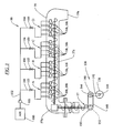
- Figures 1 and 2 show an agricultural Combine harvester 10 having a supporting structure 12 engaged has means 14 located on the ground, which are from of the supporting structure 12 extend downwards.
- Such one Combine harvester is described in detail in US 6,285,198 the disclosure of which is incorporated by reference into the present Documents is included.
- the invention can be used on any other Types of combine harvesters are used, such as conventional ones Straw walker machines.
- a cutter 16 is used to Harvest crop and feed it to an inclined conveyor 18.
- the crop is one by the feeder 18 Guide drum 20 supplied.
- the guide drum 20 guides the crop up through an inlet transition section 22 to one axial crop processing unit 24.
- the axial crop processing unit 24 is between the side walls of the combine 10 arranged and supported by them.
- the axial crop processing unit 24 comprises an axial one Rotor housing 26 and one arranged in the rotor housing 26 axial rotor 28.
- the harvested crop passes through the inlet transition section 22 into the rotor housing 26.
- the rotor 28 is with a loading section, a threshing section and equipped with a separating section.
- the rotor housing 26 has each a corresponding loading section, threshing section and Separating portion.
- Both crop processing sections of the rotor 28, the threshing section and the separating section are with good engagement assemblies fitted.
- the threshing section of the rotor housing 26 is equipped with a concave and the separating section with a rust. Grains and chaff released from the mat fall through the concave and the grate.
- the concave and the Rust prevents the passage of crop that is larger than grain or Kaff, in the cleaning system 34th
- the clean grain will then through an elevator 36 for clean grain one Filling screw conveyor 38 supplied.
- the filling screw conveyor 38 promotes the grain in a grain tank 40 or Grain bin.
- the elevator 36 for clean grain and the Filling screw conveyor 38 comprise means for moving the clean grain from the grain bottom of the combine into one Storage container, which is formed by the grain tank 40.
- the corn is discharged from the grain tank 40 by an unloading screw conveyor 57 away.
- the discharge drum 46 conveys the straw to Combine 10 back.
- the operation of the Combine harvester 10 is operated from an operator's cab 48.
- Unloading screw conveyor 56 and 58 the grain to the side of the Grain tanks 40, where it with the discharge screw conveyor 57 in Comes in contact with the clean grain by a vertical Discharge tube 61 and a horizontal discharge tube 59 conducts.
- the Unloading screw conveyor 57 comprises a vertical section 57a, which is at least partially within the unloading tube 61 is a right-angle gear 57b, and one horizontal portion 57c within the discharge tube 59.
- the discharge tube 59 normally from the side of the combine 10 to the outside extend so that clean grain easier in a cart or Trailer can be directed.
- the grain tank 40 comprises a trough 60, which is a larger one Includes trough area 70 and a smaller trough area 72, which the horizontal unloading screw conveyors 56 and 58 take up.
- the trough 60 is a loading case or sump 64 open towards.
- the vertical section 57a of the Unloading screw conveyor 57 extends through the vertical Pipe 61 and in the swamp 64. That through the horizontal Unloading screw conveyors 56 and 58 are conveyed to the grain Sump 64 dispensed and by means of the vertical section 57a through the tube 61 and by means of the horizontal section 57 c removed through the discharge tube 59.
- FIG. 3 schematically shows an inventive one Cleaning system that works with air.
- An air supply 100 indicates air under pressure via a quick coupling 103 a valve device 102.
- the quick coupling 103 can be a threaded or other type of Coupling used or be waived.
- the Air supply 100 may be outside of combine 10 are located.
- the valve device 102 comprises branch lines 104 that Air to stationary nozzles 106 or alternative nozzles 306 (such as described below).
- a isolation valve 105 is in each Branch line 104 is provided. As described below pressurized air is applied to the nozzles 106, 306, to remove grain and contaminants from the discharge tube 59 remove.
- the driven rotating system 112 includes one with 12V operated DC motor 138 which has a pulley 140 drives a belt 142 when the motor 138 is activated during cleaning operation.
- the strap 142 drives a pulley 144 which drives a gear 146 that in normal grain unloading operation from the drive train of the Combine 10 is driven at high speed.
- the Gear 146 drives a chain 148, which is a gear 150 drives a right angle gear 152 that drives the unloading screw conveyor 57.
- the relatively small motor 138 drives the cleaning operation Unloading screw conveyor 57 at a slow speed on.
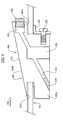
- FIG. 4 shows the horizontal unloading tube 59 in one perspective cross section.
- a nozzle 106 is shown.
- the Nozzle 106 includes a nozzle body 207 that is under pressure Air to a nozzle element 208 with an outlet opening 209 emits.
- the nozzle body 207 extends into the discharge tube 59 and nozzle member 208 is downstream lying end of the discharge tube 59 opened.
- the nozzle 106 is at an angle G above the 0 degree bottom of the Unloading tube 59 arranged.
- the angle G is preferably approximately 45 degrees.
- the outlet opening 209 of the nozzle element 208 is included directed downwards at an angle H.
- the angle H is preferably about 10 degrees.
- the nozzle body 207 includes a base block portion 207a and an inner one Block section 207b.
- a slot 207c is in the base block section 207a adjacent to the inner block portion 207b at one arranged upstream end of the nozzle body 207.
- a clamp bracket 220 is on with a screw 222 a downstream surface 207d of the base block portion 207a attached.
- a gap 207e is between a lower one Surface of the inner block portion 207b and an upper surface the clamp bracket 220 is formed.
- the clamp bracket 220 includes a slot 220a to tightly clamp the bracket 220 against one To push wall 223 of the combine 10, such as. B. the Wall of the discharge tube 59 before the screw 222 is tightened.
- An alternative design for nozzle 106 includes one snap-in plastic nozzle body, similar to that nozzle body described above, including the Base block section and the inner block section, which as are formed in one piece structure and no other means for Require connection.
- nozzle 106 includes this Nozzle element 208 that fits into an opening 228 in the interior Block section 207b is screwed.
- a through hole 232 through the base block portion 207a and the inner Block section 207b is after its manufacture by a Welding plug 234 blocked.
- the through hole 232 is communicating with opening 228.
- the nozzle element 208 can installed using a hexagon socket wrench with the nozzle element 208 in the opening 228 in the Nozzle body 207 is screwed in.
- An inlet bore 238 extends substantially perpendicular to a lower one Surface of the base block portion 207a and cuts the through hole 232.
- the inlet hole 238 is with a Thread to accommodate an air supply fitting.
- the inner block portion 207b is chamfered to an incline to form upper surface 244, the distance of which from the inner Surface of the discharge tube 59 in the direction of the grain flow 248 increases. Because of this bevel, the nozzle body 207 is in front unwanted wear protected by impacting grain, and also clogging of the unloading screw conveyor 57 with grain due to dragging the grain flow or disturbances is prevented within the unloading tube 59.
- the nozzle 106 is on and in a rectangular opening 250 in the wall 223 attached.
- the slot 207c takes a section the wall 223 and the clamp bracket 220 is against the wall 223 is pushed and the screw 222 is tightened to the wall 223 to be recorded.
- the inner block section 207b is located thus on the inside of the wall 223 and the Base block section 207a is outside wall 223. According to the embodiment shown extends the nozzle body 207 about 12 mm into the discharge tube 59 and has a distance from the drivers of the Unloading screw conveyor 57 of about 4 mm.
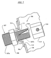
- FIG. 7 shows another nozzle 306.
- the nozzle 306 comprises a nozzle body 307 with a threaded tubular base portion 307a and one threaded provided tubular inner portion 307b, which by a Block 308 are separated by a wrench can attack.
- the base portion 307a takes a threaded one provided connection (not shown) with pressurized Air on.
- the inner portion 307b is through a hole 310 in the Unloading tube 59 inserted.
- the inner portion 307b extends also through a hole 311 in a mounting plate 59a is formed, which is welded onto the discharge tube 59.
- a lock nut 312 and a hexagonal cap 314 are screwed onto the inner section 307b around the nozzle 306 to clamp on the mounting plate 59a.
- the cap 314 includes an outlet opening 316 and inner portion 307b includes a triangular slot 318.
- Position of cap 314 along the length of the inner section 307b can be the effective size of the air opening inside the inner portion 307b set to the outlet opening 316 become.
- the locking nut 312 is then on the inside Section 307b positioned against the mounting plate 59 to clamp the cap 314.
- the orientation of the Exit opening 316 within the discharge tube 59 slightly can be changed by loosening the locking nut 312 and the nozzle body 307 is realigned.
- the compressed air cleaning system was connected to an unloading pipe Combine harvester of the applicant, type 9750 STS, tested one inner diameter of about 33 cm and a length of about 6 m Has.
- the distance of the nozzles 306 along the tube 59 was about 35 cm.
- the nozzles had orifices 316 with an effective one Diameter of about 2.4 mm at the angle G on the unloading tube 59 (see FIG. 4) of 45 degrees and with the angle H (see FIG. Figure 4) were directed downward from about 10 degrees.
- An inventive method for removing grain from an unloading tube 59 is provided which does the following Steps include: providing a variety of attached nozzles 106 or 306 within the discharge tube 59, the nozzles of the Pluralities are spaced longitudinally, and Use the nozzles by introducing air into the discharge tube 59 to grain along the unloading tube 59 and in and around the Unloading screw conveyor 57 around and out of the outlet 59a of the To promote discharge tube 59.
- the individual nozzles of the multitude can be sequential and in Groups A, B, C, D operated by nozzles in one direction along the discharge tube 59 from an upstream end near the right angle gear 57b toward the Outlet 59a of the discharge tube 59 to.
- each of the Groups operated for about 30 s to one ensure complete cleaning.
- the horizontal Section 57c is rotated slowly while the nozzles 106, 306 operated, d. H. Air flows at high speed in discharge the discharge tube 59.
Abstract
Description
Die Erfindung betrifft eine Reinigungseinrichtung für ein Entladerohr einer Erntemaschine, insbesondere eines Mähdreschers.The invention relates to a cleaning device for a Unloading tube of a harvesting machine, especially one Combine.
Landwirtschaftlich angebautes Erntegut kann als essbares Erntegut, nichtessbares Erntegut, genetisch modifizierte Organismen (GMO), nichtgenetisch modifizierte Organismen, organisch angebaut, pestizidfrei oder entsprechend anderer Eigenschaften klassifiziert werden. Nichtessbares Erntegut können beispielsweise Fasern liefernde Pflanzen, Baumwolle oder Gummi sein. Genetisch modifiziertes Erntegut kann Gemüse sein, das genetisch manipuliert wurde, um die mögliche Regalstandzeit gegenüber traditionell angebautem Gemüse zu verlängern. Organisch angebautes Erntegut wird von Pflanzen geerntet, die ohne Beaufschlagung mit bestimmten Pestiziden, Herbiziden oder anderen Chemikalien angebaut wurden.Agricultural crops can be considered edible Crop, non-edible crop, genetically modified Organisms (GMO), non-genetically modified organisms, organically grown, pesticide-free or equivalent Properties are classified. Inedible crop can, for example, plants that supply fibers, cotton or Be rubber. Genetically modified crops can be vegetables, that has been genetically manipulated to determine the shelf life to extend compared to traditionally grown vegetables. Organically grown crop is harvested from plants that without exposure to certain pesticides, herbicides or other chemicals have been grown.
Das Erntegut kann entsprechend spezifischer Eigenschaften oder Spezifikationen angebaut werden. Die Eigenschaften des Ernteguts können auf der genetischen Zusammensetzung des Ernteguts oder den Anbaupraktiken des Ernteguts beruhen, oder auf beiden. Es kann beispielsweise eine bestimmte Art von Mais angebaut werden, der aufgrund genetischer oder umgebungsbedingter Faktoren einen größeren Ölgehalt hat als andere Arten. In ähnlicher Weise kann eine bestimmte Art von Sojabohnen angebaut werden, die einen anderen Proteingehalt oder eine andere wünschenswerte Eigenschaft hat. Ein Verarbeiter, eine pharmazeutische Gesellschaft, ein Hersteller oder ein anderer Betroffener kann den Wunsch haben, landwirtschaftliche Produkte mit spezifischen Eigenschaften von einem Anbauer oder anderen Lieferanten zu erwerben. Der Anbauer oder Lieferant kann sich wünschen, für Erntegut mit spezifischen Eigenschaften einen höheren Preis zu verlangen als für ein handelsübliches Erntegut. Der Erwerber des landwirtschaftlichen Produkts kann eine hinreichende Bestätigung wünschen, dass das gekaufte landwirtschaftliche Produkt tatsächlich die gesuchten Eigenschaften aufweist. The crop can be according to specific properties or Specifications are grown. The properties of the crop can on the genetic composition of the crop or based on crop cultivation practices, or both. It for example, a certain type of corn can be grown, one due to genetic or environmental factors has greater oil content than other species. Similarly, can a certain type of soybeans are grown that one other protein content or another desirable Property. One processor, one pharmaceutical Society, a manufacturer or another affected person have a desire to produce agricultural products with specific Properties from a grower or other supplier too purchase. The grower or supplier may wish for Harvest crops with specific properties at a higher price demand than for a commercially available crop. The buyer of the agricultural product can provide sufficient confirmation wish the purchased agricultural product actually has the properties sought.
Es besteht somit ein Bedarf daran, Erntegut mit spezifischen Eigenschaften während des Anbaus und der Verteilung und jeglicher daraus abgeleiteter Produkte genau zu identifizieren. Außerdem kann ein Erwerber eines landwirtschaftlichen Produkts oder Ernteguts die Möglichkeit wünschen oder verlangen, die Identität des Ernteguts mit spezifischen Eigenschaften nachzuverfolgen, um das Vorhandensein von Eigenschaften des Ernteguts oder die Abwesenheit unerwünschter Eigenschaften als Bedingung für eine kommerzielle Transaktion zu überprüfen.There is therefore a need to crop with specific Properties during cultivation and distribution and to accurately identify any products derived from it. In addition, an acquirer of an agricultural product or crops want or require the option of Identity of the crop with specific properties to track the presence of properties of the Crop or the absence of undesirable properties as Check condition for a commercial transaction.
Es besteht demnach ein Bedarf, Erntegut während der Ernte zu trennen, damit keine Vermischung von Erntegut oder Erntegutresten mit verschiedenen Eigenschaften stattfindet. Deshalb wird eine Erntemaschine, wie ein Mähdrescher, vorzugsweise gereinigt, bevor sie bei der Ernte eines nachfolgenden Ernteguts mit anderen Eigenschaften verwendet wird.There is therefore a need to harvest crops during the harvest separate, so that no mixing of crop or Crop residue with different properties takes place. That’s why a harvester, like a combine harvester, preferably cleaned before harvesting one subsequent crops with different properties becomes.
Die typische Zeit und der zugehörige Aufwand zur vollständigen Entfernung des gesamten Korns und sämtlicher Erntegutreste aus dem Mähdrescher ist sehr lang und die Aufgabe ist schwierig. Eines der schwierigeren Probleme in der Reinigungsprozedur ist die Reinigung des horizontalen Entladerohrs. Es bestehen nur eine begrenzte Zugangsmöglichkeit und kein effektives Verfahren, zwecks einer geeigneten Reinigung Zugang zum Rohr zu bekommen.The typical time and effort involved to complete Removal of all grain and all crop residues the combine is very long and the task is difficult. One of the more difficult problems in the cleaning procedure is cleaning the horizontal discharge tube. There are only limited access and no effective process, to get access to the pipe for proper cleaning.
Das der Erfindung zu Grunde liegende Problem wird darin gesehen, die genannten Probleme zu überwinden.The problem underlying the invention is seen in to overcome the problems mentioned.
Diese Aufgabe wird erfindungsgemäß durch die Lehre des Patentanspruchs
1 gelöst, wobei in den weiteren Patentansprüchen Merkmale
aufgeführt sind, die die Lösung in vorteilhafter Weise
weiterentwickeln.This object is achieved by the teaching of the
Die Erfindung stellt ein Düsensystem und einen Düsenentwurf zur Verwendung in zu reinigenden Bereichen von Erntemaschinen bereit. Bei einem Beispiel einer Ausführungsform wird ein strombasierendes Reinigungssystem für ein Entladerohr einer Erntemaschine, wie eines Mähdreschers, bereitgestellt. Das Entladerohr enthält einen Entladeschneckenförderer und eine Vielzahl von Düsen, die in der Regel teilweise innerhalb des Entladerohrs angebracht sind. Die Düsen haben Austrittsöffnungen, die im Wesentlichen in Längsrichtung des Entladerohrs ausgerichtet sind, um das Innere des Entladerohrs mit Strömen hoher Geschwindigkeit auszusetzen und dadurch eine Reinigung des Entladerohrs von Korn und anderen Resten zu bewirken. Die Düsen sind mit Leitungen verbunden, die unter Druck stehendes Medium bereitstellen. Das zur Reinigung des Entladerohrs aus den Düsen strömende Medium kann Luft, ein anderes Gas oder Gasgemisch oder eine Flüssigkeit sein, wie Wasser, Alkohol oder eine Seifenlösung. Die Leitungen können mit geeigneten Ventilen verbunden sein.The invention provides a nozzle system and design Use in areas of harvesters to be cleaned ready. In one example of an embodiment, a current-based cleaning system for a discharge tube Harvester, such as a combine harvester. The unloading tube contains a discharge screw conveyor and a variety of nozzles, which are usually partially inside the discharge tube are attached. The nozzles have outlet openings, which are oriented essentially in the longitudinal direction of the unloading tube are high to the inside of the discharge tube with currents Suspend speed and thereby cleaning the To cause discharge of grain and other residues. The nozzles are connected to lines that are pressurized medium provide. That for cleaning the discharge tube from the nozzles flowing medium can be air, another gas or gas mixture or be a liquid, such as water, alcohol, or Soap solution. The lines can be fitted with suitable valves be connected.
Auf diese Weise wird eine Möglichkeit bereitgestellt, zwischen der Ernte von Erntegut mit unterschiedlichen Eigenschaften das Entladerohr eines Mähdreschers schnell, einfach und gründlich von Korn und Verunreinigungen zu befreien.In this way, a way is provided between harvesting crops with different characteristics Unloading tube of a combine harvester quickly, easily and thoroughly to get rid of grain and impurities.
Die Düsen können Gehäuse oder Körper aufweisen, die eine Wand des Entladerohrs durchdringen. Die Körper haben innerhalb des Entladerohrs ein in Flussrichtung abgeschrägtes Profil, um den Widerstand auf den Kornfluss im Entladerohr während des normalen Entladebetriebs zu minimieren.The nozzles can have housings or bodies that have a wall penetrate the discharge tube. The bodies have within the Unloading tube a profile tapered in the direction of flow to the Resistance to the grain flow in the unloading tube during normal To minimize unloading.
Die Düsen sind in Längsrichtung des Entladerohrs voneinander beabstandet angeordnet. Sie befinden sich vorzugsweise 45 Grad oberhalb eines Bodens des Entladerohrs, wobei ihre Austrittsöffnungen vorzugsweise etwa 10 Grad aus der Horizontalen nach unten geneigt sind.The nozzles are in the longitudinal direction of the unloading tube spaced apart. They are preferably 45 degrees above a bottom of the unloading tube, their Exit openings preferably about 10 degrees from the Horizontal are inclined downwards.
Der Entladeschneckenförderer kann sich drehen, während Luft in das Entladerohr geleitet wird.The discharge screw conveyor can rotate while air is in the discharge tube is directed.
Die Düsen können nacheinander und in Gruppen von Düsen betrieben werden, wobei zuerst die Düsen am Einlassende und danach die dem Auslassende des Entladerohrs näheren Düsen betrieben werden. The nozzles can be operated in succession and in groups of nozzles are, first the nozzles at the inlet end and then the Nozzles near the outlet end of the discharge tube are operated.
In den Zeichnungen ist ein nachfolgend näher beschriebenes Ausführungsbeispiel der Erfindung dargestellt. Es zeigt:
- Fig. 1
- eine schematische Seitenansicht einer Erntemaschine, in der die vorliegende Erfindung verwirklicht ist,
- Fig. 2
- eine schematische Draufsicht auf die
Erntemaschine aus
Figur 1, - Fig. 3
- ein schematisches Diagramm eines erfindungsgemäßen Reinigungssystems, das mit Druckluft arbeitet,
- Fig. 4
- eine perspektivische Ansicht eines Abschnitts des Entladerohrs,
- Fig. 5
- eine perspektivische Ansicht einer in Figur 4 gezeigten Luftdüse,
- Fig. 6
- eine Schnittansicht, die im Wesentlichen entlang der Linie 6-6 in Figur 5 aufgenommen ist, und
- Fig. 7
- eine vergrößerte perspektivische Explosionszeichnung, teilweise im Schnitt gezeichnet, von einer anderen Ausführungsform einer Luftdüse, die am Entladerohr befestigt ist.
- Fig. 1
- 2 shows a schematic side view of a harvesting machine in which the present invention is implemented,
- Fig. 2
- 2 shows a schematic top view of the harvesting machine from FIG. 1,
- Fig. 3
- 1 shows a schematic diagram of a cleaning system according to the invention, which works with compressed air,
- Fig. 4
- a perspective view of a portion of the unloading tube,
- Fig. 5
- 3 shows a perspective view of an air nozzle shown in FIG. 4,
- Fig. 6
- a sectional view taken substantially along the line 6-6 in Figure 5, and
- Fig. 7
- an enlarged perspective exploded view, partly drawn in section, of another embodiment of an air nozzle which is attached to the discharge tube.
Die Figuren 1 und 2 zeigen einen landwirtschaftlichen
Mähdrescher 10, der eine tragende Struktur 12 mit im Eingriff
mit dem Erdboden befindlichen Mitteln 14 aufweist, die sich von
der tragenden Struktur 12 nach unten erstrecken. Ein derartiger
Mähdrescher ist in der US 6 285 198 detailliert beschrieben,
deren Offenbarung durch Verweis mit in die vorliegenden
Unterlagen aufgenommen wird. Anstelle des dargestellten
Axialmähdreschers kann die Erfindung auch an beliebigen anderen
Typen von Mähdreschern verwendet werden, wie konventionellen
Strohschüttlermaschinen. Ein Schneidwerk 16 wird verwendet, um
Erntegut zu ernten und es einem Schrägförderer 18 zuzuführen. Figures 1 and 2 show an
Das geerntete Gut wird durch den Schrägförderer 18 einer
Leittrommel 20 zugeführt. Die Leittrommel 20 führt das Erntegut
nach oben durch einen Einlassübergangsabschnitt 22 zu einer
axialen Gutbearbeitungseinheit 24. Die axiale Gutbearbeitungseinheit
24 ist zwischen den Seitenwänden des Mähdreschers 10
angeordnet und wird von ihnen abgestützt.The crop is one by the
Die axiale Gutbearbeitungseinheit 24 umfasst ein axiales
Rotorgehäuse 26 und einen im Rotorgehäuse 26 angeordneten
axialen Rotor 28. Das geerntete Gut tritt durch den Einlassübergangsabschnitt
22 in das Rotorgehäuse 26 ein. Der Rotor 28
ist mit einem Beschickungsabschnitt, einem Dreschabschnitt und
einem Trennabschnitt ausgestattet. Das Rotorgehäuse 26 hat je
einen entsprechenden Beschickungsabschnitt, Dreschabschnitt und
Trennabschnitt.The axial
Beide Gutbearbeitungsabschnitte des Rotors 28, der Dreschabschnitt
und der Trennabschnitt sind mit Guteingriffszusammenbauten
ausgestattet. Der Dreschabschnitt des Rotorgehäuses 26
ist mit einem Dreschkorb ausgestattet und der Trennabschnitt mit
einem Rost. Aus der Gutmatte freigesetzte Körner und Spreu
fallen durch den Dreschkorb und den Rost. Der Dreschkorb und der
Rost verhindern den Durchtritt von Erntegut, das größer als Korn
oder Kaff ist, in das Reinigungssystem 34.Both crop processing sections of the
Wie in der Figur 1 dargestellt, wird durch den Dreschkorb und
den Rost fallendes Korn und Spreu dem Reinigungssystem 34
zugeführt, das die Spreu vom Korn trennt. Das saubere Korn wird
dann durch einen Elevator 36 für sauberes Korn einem
Befüllschneckenförderer 38 zugeführt. Der Befüllschneckenförderer
38 fördert das Korn in einen Korntank 40 oder
Kornbehälter. Der Elevator 36 für sauberes Korn und der
Befüllschneckenförderer 38 umfassen Mittel zum Bewegen des
sauberen Korns vom Kornboden des Mähdreschers in einen
Vorratsbehälter, der vom Korntank 40 gebildet wird. Das Korn
wird durch einen Entladeschneckenförderer 57 aus dem Korntank 40
entfernt. Wenn das Stroh das Ende der Gutbearbeitungseinheit 24
erreicht hat, wird es durch einen Auslass einer Auswurftrommel
46 zugeführt. Die Auswurftrommel 46 fördert das Stroh zur
Rückseite des Mähdreschers 10 hinaus. Die Bedienung des
Mähdreschers 10 erfolgt von einer Bedienerkabine 48 aus.As shown in Figure 1, the concave and
the rust falling grain and chaff the cleaning system 34
fed, which separates the chaff from the grain. The clean grain will
then through an
Wenn der Korntank 40 zu entleeren ist, führen quer angeordnete
Entladeschneckenförderer 56 und 58 das Korn an die Seite des
Korntanks 40, wo es mit dem Entladeschneckenförderer 57 in
Berührung kommt, der das saubere Korn durch ein vertikales
Entladerohr 61 und ein horizontales Entladerohr 59 leitet. Der
Entladeschneckenförderer 57 umfasst einen vertikalen Abschnitt
57a, der sich zumindest teilweise innerhalb des Entladerohrs 61
befindet, ein rechtwinkliges Getriebe 57b, und einen
horizontalen Abschnitt 57c innerhalb des Entladerohrs 59.
Während einer Entladeoperation würde sich das Entladerohr 59
normalerweise von der Seite des Mähdreschers 10 nach außen
erstrecken, so dass sauberes Korn einfacher in einen Wagen oder
Anhänger geleitet werden kann.If the
Der Korntank 40 umfasst einen Trog 60, der einen größeren
Trogbereich 70 und einen kleineren Trogbereich 72 umfasst,
welche die horizontalen Entladeschneckenförderer 56 und 58
aufnehmen. Der Trog 60 ist zu einem Ladegehäuse oder Sumpf 64
hin offen. Der vertikale Abschnitt 57a des
Entladeschneckenförderers 57 erstreckt sich durch das vertikale
Rohr 61 und in den Sumpf 64. Das durch die horizontalen
Entladeschneckenförderer 56 und 58 geförderte Korn wird in den
Sumpf 64 abgegeben und mittels des vertikalen Abschnitts 57a
durch das Rohr 61 und mittels des horizontalen Abschnitts 57 c
durch das Entladerohr 59 entfernt.The
Die Figur 3 zeigt in schematischer Weise ein erfindungsgemäßes
Reinigungssystem, das mit Luft arbeitet. Eine Luftversorgung 100
gibt über eine Schnellkupplung 103 unter Druck stehende Luft an
eine Ventileinrichtung 102 ab. Alternativ zur Schnellkupplung
103 kann eine mit Gewinden versehene oder eine andere Art einer
Kupplung verwendet oder darauf verzichtet werden. Die
Luftversorgung 100 kann sich außerhalb des Mähdreschers 10
befinden. Die Ventileinrichtung 102 umfasst Zweiglinien 104, die
Luft an stationäre Düsen 106 oder alternative Düsen 306 (wie
unten beschrieben) abgeben. Ein Trennventil 105 ist in jeder
Zweiglinie 104 vorgesehen. Wie weiter unten beschrieben, werden
die Düsen 106, 306 mit unter Druck stehender Luft beaufschlagt,
um Korn und Verunreinigungen aus dem Entladerohr 59 zu
entfernen.FIG. 3 schematically shows an inventive one
Cleaning system that works with air. An
Um die Reinigungsoperation zu verstärken wird der
Entladeschneckenförderer 57 einschließlich des horizontalen
Abschnitts 57c durch ein angetriebenes Drehsystem 112 langsam
gedreht. Ein derartiges Drehsystem ist in der
prioritätsdatumsgleichen US-Patentanmeldung 10/309977
beschrieben, deren Offenbarung durch Verweis mit in die
vorliegenden Unterlagen aufgenommen wird.To strengthen the cleaning operation, the
Das angetriebene Drehsystem 112 umfasst einen mit 12 V
betriebenen Gleichstrommotor 138, der eine Riemenscheibe 140
antreibt, die einen Riemen 142 antreibt, wenn der Motor 138
während des Reinigungsbetriebs aktiviert wird. Der Riemen 142
treibt eine Riemenscheibe 144 an, die ein Zahnrad 146 antreibt,
das bei normalem Kornentladebetrieb vom Antriebsstrang des
Mähdreschers 10 mit hoher Geschwindigkeit angetrieben wird. Das
Zahnrad 146 treibt eine Kette 148 an, die ein Zahnrad 150
antreibt, welches ein rechtwinkliges Getriebe 152 antreibt, das
den Entladeschneckenförderer 57 antreibt. Während des
Reinigungsbetriebs treibt der relativ kleine Motor 138 den
Entladeschneckenförderer 57 mit einer langsamen Geschwindigkeit
an.The driven rotating system 112 includes one with 12V
operated
Die Figur 4 zeigt das horizontale Entladerohr 59 in einem
perspektivischen Querschnitt. Es wird eine Düse 106 gezeigt. Die
Düse 106 umfasst einen Düsenkörper 207, der unter Druck stehende
Luft an ein Düsenelement 208 mit einer Austrittsöffnung 209
abgibt. Der Düsenkörper 207 erstreckt sich in das Entladerohr 59
und das Düsenelement 208 ist in Richtung auf ein stromab
liegendes Ende des Entladerohrs 59 geöffnet. Die Düse 106 ist
bei einem Winkel G oberhalb des bei 0 Grad liegenden Bodens des
Entladerohrs 59 angeordnet. Der Winkel G ist vorzugsweise etwa
45 Grad. Die Austrittsöffnung 209 des Düsenelement 208 ist mit
einem Winkel H nach unten gerichtet. Der Winkel H beträgt
vorzugsweise etwa 10 Grad. FIG. 4 shows the
In Figur 5 ist eine Düse 106 dargestellt. Der Düsenkörper 207
umfasst einen Basisblockabschnitt 207a und einen inneren
Blockabschnitt 207b. Ein Schlitz 207c ist im Basisblockabschnitt
207a benachbart zum inneren Blockabschnitt 207b an einem
stromauf liegenden Ende des Düsenkörpers 207 angeordnet. An
einem stromab liegenden Ende des Basisblockabschnitts 207a ragt
der innere Blockabschnitt 207b über den Basisblockabschnitt 207a
hinaus. Eine Klemmhalterung 220 ist mit einer Schraube 222 an
einer stromab liegenden Fläche 207d des Basisblockabschnitts
207a befestigt. Eine Lücke 207e ist zwischen einer unteren
Fläche des inneren Blockabschnitts 207b und einer oberen Fläche
der Klemmhalterung 220 gebildet. Die Klemmhalterung 220 umfasst
einen Schlitz 220a, um die Klemmhalterung 220 eng gegen eine
Wand 223 des Mähdreschers 10 schieben zu können, wie z. B. die
Wand des Entladerohrs 59, bevor die Schraube 222 angezogen wird.
Ein alternatives Design für die Düse 106 umfasst einen
einschnappenden Düsenkörper aus Kunststoff, der ähnlich dem
zuvor beschriebenen Düsenkörper ist, einschließlich des
Basisblockabschnitts und des inneren Blockabschnitts, die als
einteilige Struktur geformt sind und keine weiteren Mittel zum
Anklemmen erfordern.A
Wie in der Figur 6 gezeigt, umfasst die Düse 106 das
Düsenelement 208, das in eine Öffnung 228 in dem inneren
Blockabschnitt 207b eingeschraubt ist. Eine durchgehende Bohrung
232 durch den Basisblockabschnitt 207a und den inneren
Blockabschnitt 207b ist nach ihrer Herstellung durch einen
Schweißstopfen 234 verstopft. Die durchgehende Bohrung 232 steht
mit der Öffnung 228 in Verbindung. Das Düsenelement 208 kann
unter Verwendung eines Sechskantsteckschlüssels installiert
werden, wobei das Düsenelement 208 in die Öffnung 228 im
Düsenkörper 207 eingeschraubt wird. Eine Einlassbohrung 238
erstreckt sich im Wesentlichen senkrecht zu einer unteren
Oberfläche des Basisblockabschnitts 207a und schneidet die
durchgehende Bohrung 232. Die Einlassbohrung 238 ist mit einem
Gewinde versehen, um ein Luftversorgungsfitting aufzunehmen.As shown in Figure 6,
Der innere Blockabschnitt 207b ist abgeschrägt, um eine geneigte
obere Fläche 244 zu bilden, deren Entfernung von der inneren
Oberfläche des Entladerohrs 59 in Richtung des Kornflusses 248
ansteigt. Wegen dieser Schrägung ist der Düsenkörper 207 vor
unerwünschter Abnutzung durch auftreffendes Korn geschützt, und
auch eine Verstopfung des Entladeschneckenförderers 57 mit Korn
auf Grund von Mitziehens des Kornflusses oder Störungen
innerhalb des Entladerohrs 59 ist unterbunden.The
Die Düse 106 ist auf und in einer rechteckigen Öffnung 250 in
der Wand 223 angebracht. Der Schlitz 207c nimmt einen Abschnitt
der Wand 223 auf und die Klemmhalterung 220 wird gegen die Wand
223 geschoben und die Schraube 222 wird angezogen, um die Wand
223 zu erfassen. Der innere Blockabschnitt 207b befindet sich
somit auf der Innenseite der Wand 223 und der
Basisblockabschnitt 207a befindet sich außerhalb der Wand 223.
Entsprechend der dargestellten Ausführungsform erstreckt sich
der Düsenkörper 207 etwa 12 mm in das Entladerohr 59 hinein und
hat einen Abstand von den Mitnehmern des
Entladeschneckenförderers 57 von etwa 4 mm.The
Die Figur 7 zeigt eine andere Düse 306. Die Düse 306 umfasst
einen Düsenkörper 307 mit einem mit Gewinde versehenen,
rohrförmigen Basisabschnitt 307a und einen mit Gewinde
versehenen, rohrförmigen inneren Abschnitt 307b, die durch einen
Block 308 voneinander getrennt sind, an dem ein Gabelschlüssel
angreifen kann. Der Basisabschnitt 307a nimmt eine mit Gewinde
versehene Verbindung (nicht gezeigt) mit unter Druck stehender
Luft auf. Der innere Abschnitt 307b wird durch ein Loch 310 im
Entladerohr 59 eingesetzt. Der innere Abschnitt 307b erstreckt
sich auch durch ein Loch 311, das in einer Befestigungsplatte
59a gebildet ist, die auf das Entladerohr 59 aufgeschweißt ist.
Eine Arretierungsmutter 312 und eine sechseckige Kappe 314
werden auf den inneren Abschnitt 307b geschraubt, um die Düse
306 an der Befestigungsplatte 59a festzuklemmen. Die Kappe 314
umfasst eine Austrittsöffnung 316 und der innere Abschnitt 307b
umfasst einen dreieckigen Schlitz 318. Durch die Auswahl der
Position der Kappe 314 entlang der Länge des inneren Abschnitts
307b kann die effektive Größe der Luftöffnung der Innenseite des
inneren Abschnitts 307b zur Austrittsöffnung 316 eingestellt
werden. Die Arretierungsmutter 312 wird dann am inneren
Abschnitt 307b positioniert, um die Befestigungsplatte 59 gegen
die Kappe 314 zu klemmen.FIG. 7 shows another
Durch die Verwendung dieser Düse 306 kann die Orientierung der
Austrittsöffnung 316 innerhalb des Entladerohrs 59 leicht
geändert werden, indem die Verriegelungsmutter 312 gelöst und
der Düsenkörper 307 neu ausgerichtet wird. Vorzugsweise wird die
Austrittsöffnung 316 in einem Abstand von etwa 1 bis 2 mm von
der inneren Oberfläche des Entladerohrs 59 positioniert.By using this
Das Druckluftreinigungssystem wurde an einem Entladerohr eines
Mähdreschers der Anmelderin, Typ 9750 STS, getestet, das einen
inneren Durchmesser von etwa 33 cm und eine Länge von etwa 6 m
hat. Es wurden vier Gruppen A, B, C, D mit vier Düsen 306
verwendet, jede Gruppe durch eine separate Zweigleitung 104 und
ein Trennventil 105 beaufschlagt. Bei gegebener Länge des Rohrs
59 war der Abstand der Düsen 306 entlang des Rohrs 59 etwa 35
cm. Die Düsen hatten Austrittsöffnungen 316 mit einem effektiven
Durchmesser von etwa 2,4 mm, die bei dem Winkel G am Entladerohr
59 (s. Figur 4) von 45 Grad angebracht und mit dem Winkel H (s.
Figur 4) von etwa 10 Grad nach unten gerichtet waren. Während
der horizontale Abschnitt 57c des Entladeschneckenförderers 57
langsam gedreht wurde, wurden die Gruppen A, B, C, D der Düsen
306 nacheinander mit unter einem Druck von etwa 56 kPa (80 psi)
stehender Luft beaufschlagt, von der Gruppe A, den am nächsten
zum rechtwinkligen Getriebe 57b angeordneten Düsen 306 bis zur
Gruppe D, den einem offenen Ende 59a (Figur 2) des Entladerohrs
59 nächsten Düsen 306, für eine Dauer von etwa 10 s für jede der
Gruppen A, B, C, D. Es wurden sehr effektive Reinigungsergebnisse
erzielt.The compressed air cleaning system was connected to an unloading pipe
Combine harvester of the applicant, type 9750 STS, tested one
inner diameter of about 33 cm and a length of about 6 m
Has. There were four groups A, B, C, D with four
Ein erfindungsgemäßes Verfahren zur Entfernung von Korn aus
einem Entladerohr 59 wird bereitgestellt, das die folgenden
Schritte umfasst: Bereitstellen einer Vielzahl befestigter Düsen
106 oder 306 innerhalb des Entladerohrs 59, die Düsen der
Vielzahl werden in Längsrichtung beabstandet angeordnet, und
Verwenden der Düsen, indem Luft in das Entladerohr 59 geleitet
wird, um Korn entlang des Entladerohrs 59 und in und um den
Entladeschneckenförderer 57 herum und aus dem Auslass 59a des
Entladerohrs 59 zu fördern.An inventive method for removing grain from
an unloading
Die einzelnen Düsen der Vielzahl können sequentiell und in
Gruppen A, B, C, D von Düsen betrieben werden, in einer Richtung
entlang des Entladerohrs 59 von einem stromauf liegenden Ende
nahe des rechtwinkligen Getriebes 57b in Richtung auf den
Auslass 59a des Entladerohrs 59 zu. Vorzugsweise wird jede der
Gruppen für eine Zeit von etwa 30 s betrieben, um eine
vollständige Reinigung sicherzustellen.The individual nozzles of the multitude can be sequential and in
Groups A, B, C, D operated by nozzles in one direction
along the
Um den Reinigungsvorgang zu verbessern kann der horizontale
Abschnitt 57c langsam gedreht werden, während die Düsen 106, 306
betrieben werden, d. h. Luftströme mit hoher Geschwindigkeit in
das Entladerohr 59 abgeben.To improve the cleaning process, the
Claims (9)
Applications Claiming Priority (2)
| Application Number | Priority Date | Filing Date | Title |
|---|---|---|---|
| US309978 | 2002-12-04 | ||
| US10/309,978 US6736722B1 (en) | 2002-12-04 | 2002-12-04 | Unloader tube cleaning system for harvesting apparatus |
Publications (2)
| Publication Number | Publication Date |
|---|---|
| EP1425954A1 true EP1425954A1 (en) | 2004-06-09 |
| EP1425954B1 EP1425954B1 (en) | 2006-05-31 |
Family
ID=32298093
Family Applications (1)
| Application Number | Title | Priority Date | Filing Date |
|---|---|---|---|
| EP03027714A Expired - Lifetime EP1425954B1 (en) | 2002-12-04 | 2003-12-02 | Cleaning device for an unloading tube of a harvester |
Country Status (7)
| Country | Link |
|---|---|
| US (1) | US6736722B1 (en) |
| EP (1) | EP1425954B1 (en) |
| AR (1) | AR042271A1 (en) |
| BR (1) | BR0305337B1 (en) |
| CA (1) | CA2448608C (en) |
| DE (1) | DE50303556D1 (en) |
| DK (1) | DK1425954T3 (en) |
Cited By (2)
| Publication number | Priority date | Publication date | Assignee | Title |
|---|---|---|---|---|
| EP1491082B2 (en) † | 2003-06-25 | 2009-08-19 | CLAAS Selbstfahrende Erntemaschinen GmbH | Process for cleaning the working tools in an agricultural machine |
| CN107950174A (en) * | 2013-03-18 | 2018-04-24 | 株式会社久保田 | Combine harvester |
Families Citing this family (6)
| Publication number | Priority date | Publication date | Assignee | Title |
|---|---|---|---|---|
| US7167750B2 (en) * | 2003-02-03 | 2007-01-23 | Enteromedics, Inc. | Obesity treatment with electrically induced vagal down regulation |
| US20040172084A1 (en) * | 2003-02-03 | 2004-09-02 | Knudson Mark B. | Method and apparatus for treatment of gastro-esophageal reflux disease (GERD) |
| US8246751B2 (en) | 2010-10-01 | 2012-08-21 | General Electric Company | Pulsed detonation cleaning systems and methods |
| US9033643B1 (en) * | 2012-03-13 | 2015-05-19 | Ronald J. Kile | Combine harvester grain bulk tank unloading system |
| DE102017119377B3 (en) | 2017-08-24 | 2018-08-16 | Karl Schnell Gmbh & Co. Kg | Cleaning device and method for cleaning a screw conveyor |
| US10806077B2 (en) * | 2017-11-10 | 2020-10-20 | Deere & Company | Agricultural combine with electrostatic grain cleaner |
Citations (2)
| Publication number | Priority date | Publication date | Assignee | Title |
|---|---|---|---|---|
| DE449393C (en) * | 1925-12-11 | 1927-09-12 | Gotthilf Seitz | Device for conveying flour or semolina-like material by means of compressed air |
| WO2002028751A1 (en) * | 2000-10-04 | 2002-04-11 | Krämer Ag Bassersdorf | Self-cleaning oscillating conveyor for deburring, dedusting and the onward transport of small parts |
Family Cites Families (18)
| Publication number | Priority date | Publication date | Assignee | Title |
|---|---|---|---|---|
| US3880355A (en) | 1974-04-08 | 1975-04-29 | Graco Inc | Air blow gun |
| CA1132026A (en) | 1979-08-13 | 1982-09-21 | Versatile Cornat Corporation | Rotary combine |
| US4397319A (en) | 1981-03-31 | 1983-08-09 | Deere & Company | Cleaning device for harvesting machines |
| US4400131A (en) | 1981-08-31 | 1983-08-23 | The Marmon Group, Inc. | Compressed air discharge system for trucks |
| US4594840A (en) | 1983-12-12 | 1986-06-17 | Sperry Corporation | Pneumatic system for combine header height control |
| US4688308A (en) | 1985-08-26 | 1987-08-25 | Alvarez Ramon A | Mobile radiator shop |
| DE3775215D1 (en) | 1987-05-19 | 1992-01-23 | Ford New Holland Inc | CLEANING MACHINE CLEANING DEVICE. |
| US5088960A (en) | 1991-03-15 | 1992-02-18 | Deere & Company | Air blast for cleaning axial separator |
| IT1249087B (en) | 1991-03-29 | 1995-02-11 | Josef Prenn | AIR FILTER CLEANING DEVICE |
| GB2293080A (en) | 1994-09-17 | 1996-03-20 | New Holland Belguim Nv | Grain cleaner for combine harvester |
| US5546630A (en) | 1995-01-04 | 1996-08-20 | Long; Andre | Blast wiper for motor vehicle lights |
| US5507841A (en) | 1995-04-20 | 1996-04-16 | Uniwave, Inc. | Fan cleaner apparatus |
| DE19515895A1 (en) | 1995-04-29 | 1996-10-31 | Bosch Gmbh Robert | Compressed air supply device for vehicle compressed air systems and method for controlling the compressed air supply device |
| CA2182989C (en) | 1995-09-01 | 2001-03-27 | Frederick William Nelson | Grain moisture sensor |
| US6058690A (en) | 1997-01-29 | 2000-05-09 | Rutt; Larry L. | Harvester |
| JPH11137064A (en) | 1997-11-07 | 1999-05-25 | Mitsubishi Agricult Mach Co Ltd | System for removing remaining in combine harvester |
| JP4331334B2 (en) | 1999-07-21 | 2009-09-16 | セイレイ工業株式会社 | Lost grain recovery device in grain harvester |
| US6290361B1 (en) | 2000-11-01 | 2001-09-18 | Leonid Berzin | Universal clearing air system for windows and external mirrors of a vehicle |
-
2002
- 2002-12-04 US US10/309,978 patent/US6736722B1/en not_active Expired - Fee Related
-
2003
- 2003-11-07 CA CA002448608A patent/CA2448608C/en not_active Expired - Fee Related
- 2003-11-27 BR BRPI0305337-7A patent/BR0305337B1/en not_active IP Right Cessation
- 2003-12-02 EP EP03027714A patent/EP1425954B1/en not_active Expired - Lifetime
- 2003-12-02 DK DK03027714T patent/DK1425954T3/en active
- 2003-12-02 AR ARP030104439A patent/AR042271A1/en active IP Right Grant
- 2003-12-02 DE DE50303556T patent/DE50303556D1/en not_active Expired - Lifetime
Patent Citations (2)
| Publication number | Priority date | Publication date | Assignee | Title |
|---|---|---|---|---|
| DE449393C (en) * | 1925-12-11 | 1927-09-12 | Gotthilf Seitz | Device for conveying flour or semolina-like material by means of compressed air |
| WO2002028751A1 (en) * | 2000-10-04 | 2002-04-11 | Krämer Ag Bassersdorf | Self-cleaning oscillating conveyor for deburring, dedusting and the onward transport of small parts |
Cited By (2)
| Publication number | Priority date | Publication date | Assignee | Title |
|---|---|---|---|---|
| EP1491082B2 (en) † | 2003-06-25 | 2009-08-19 | CLAAS Selbstfahrende Erntemaschinen GmbH | Process for cleaning the working tools in an agricultural machine |
| CN107950174A (en) * | 2013-03-18 | 2018-04-24 | 株式会社久保田 | Combine harvester |
Also Published As
| Publication number | Publication date |
|---|---|
| CA2448608C (en) | 2007-06-19 |
| DK1425954T3 (en) | 2006-10-02 |
| EP1425954B1 (en) | 2006-05-31 |
| BR0305337B1 (en) | 2011-01-11 |
| US20040110551A1 (en) | 2004-06-10 |
| CA2448608A1 (en) | 2004-06-04 |
| DE50303556D1 (en) | 2006-07-06 |
| AR042271A1 (en) | 2005-06-15 |
| AU2003257873A1 (en) | 2004-06-24 |
| BR0305337A (en) | 2004-08-31 |
| US6736722B1 (en) | 2004-05-18 |
Similar Documents
| Publication | Publication Date | Title |
|---|---|---|
| DE60013772T2 (en) | DESTINATION FOR DRILLING AND SEPARATING UNIT OF A COMBINE | |
| DE2948272C2 (en) | ||
| EP0958733B1 (en) | Rotor for axial flow thresher-separator device | |
| EP0514820B1 (en) | Tooth, holder, tooth attachment device and axial separator | |
| EP2425725A1 (en) | Apparatus for washing and/or rinsing unpackaged vegetables or fruit | |
| EP1236391A1 (en) | Device for the treatment of crop for a combine | |
| EP1425952B1 (en) | Cleaning device for a storage tank of a harvester | |
| EP1425954B1 (en) | Cleaning device for an unloading tube of a harvester | |
| DE102013226436B4 (en) | Feederhouse for a combine harvester | |
| DE3822689C2 (en) | ||
| EP1078568B1 (en) | Device for the treatment of crop for a combine harvester | |
| DE1945401A1 (en) | Self-propelled combine harvester with axial threshing machine | |
| EP1425953B1 (en) | Harvester with unloading conveyor | |
| DE2943838C2 (en) | ||
| DE3533773A1 (en) | SELF-DRIVING FIELD CHOPPER | |
| DE102009002102A1 (en) | System for adding ensilage agent into flow of harvested goods for field chopper, has tank connected with injection nozzle, which introduces agent into harvested goods, where nozzle introduces agent into air flow | |
| EP1806047B1 (en) | Rotor of a crop treatment device of a combine harvester | |
| EP1226747A1 (en) | Drum with interchangeable feeding elements | |
| EP1425951B1 (en) | Harvester with unloading conveyor | |
| EP1709868B1 (en) | Apparatus for mixing and distributing bulk products | |
| EP1425950B1 (en) | Container and plug | |
| DE1929865A1 (en) | Fertilizer or seed distributor | |
| EP1151660B1 (en) | Harvester especially self-propelled forage harvester | |
| DD202487A5 (en) | SELF-DRIVING MAEHDRESCHER | |
| DE4209503C2 (en) | Device for self-propelled combine harvesters |
Legal Events
| Date | Code | Title | Description |
|---|---|---|---|
| PUAI | Public reference made under article 153(3) epc to a published international application that has entered the european phase |
Free format text: ORIGINAL CODE: 0009012 |
|
| AK | Designated contracting states |
Kind code of ref document: A1 Designated state(s): AT BE BG CH CY CZ DE DK EE ES FI FR GB GR HU IE IT LI LU MC NL PT RO SE SI SK TR |
|
| AX | Request for extension of the european patent |
Extension state: AL LT LV MK |
|
| 17P | Request for examination filed |
Effective date: 20041209 |
|
| AKX | Designation fees paid |
Designated state(s): BE DE DK FR GB IT |
|
| GRAP | Despatch of communication of intention to grant a patent |
Free format text: ORIGINAL CODE: EPIDOSNIGR1 |
|
| GRAS | Grant fee paid |
Free format text: ORIGINAL CODE: EPIDOSNIGR3 |
|
| GRAA | (expected) grant |
Free format text: ORIGINAL CODE: 0009210 |
|
| AK | Designated contracting states |
Kind code of ref document: B1 Designated state(s): BE DE DK FR GB IT |
|
| REG | Reference to a national code |
Ref country code: GB Ref legal event code: FG4D Free format text: NOT ENGLISH |
|
| REF | Corresponds to: |
Ref document number: 50303556 Country of ref document: DE Date of ref document: 20060706 Kind code of ref document: P |
|
| GBT | Gb: translation of ep patent filed (gb section 77(6)(a)/1977) |
Effective date: 20060717 |
|
| REG | Reference to a national code |
Ref country code: DK Ref legal event code: T3 |
|
| ET | Fr: translation filed | ||
| PLBE | No opposition filed within time limit |
Free format text: ORIGINAL CODE: 0009261 |
|
| STAA | Information on the status of an ep patent application or granted ep patent |
Free format text: STATUS: NO OPPOSITION FILED WITHIN TIME LIMIT |
|
| 26N | No opposition filed |
Effective date: 20070301 |
|
| PGFP | Annual fee paid to national office [announced via postgrant information from national office to epo] |
Ref country code: GB Payment date: 20131227 Year of fee payment: 11 |
|
| PGFP | Annual fee paid to national office [announced via postgrant information from national office to epo] |
Ref country code: IT Payment date: 20131223 Year of fee payment: 11 Ref country code: FR Payment date: 20131217 Year of fee payment: 11 |
|
| GBPC | Gb: european patent ceased through non-payment of renewal fee |
Effective date: 20141202 |
|
| REG | Reference to a national code |
Ref country code: FR Ref legal event code: ST Effective date: 20150831 |
|
| PG25 | Lapsed in a contracting state [announced via postgrant information from national office to epo] |
Ref country code: GB Free format text: LAPSE BECAUSE OF NON-PAYMENT OF DUE FEES Effective date: 20141202 |
|
| PG25 | Lapsed in a contracting state [announced via postgrant information from national office to epo] |
Ref country code: FR Free format text: LAPSE BECAUSE OF NON-PAYMENT OF DUE FEES Effective date: 20141231 |
|
| PG25 | Lapsed in a contracting state [announced via postgrant information from national office to epo] |
Ref country code: IT Free format text: LAPSE BECAUSE OF NON-PAYMENT OF DUE FEES Effective date: 20141202 |
|
| PGFP | Annual fee paid to national office [announced via postgrant information from national office to epo] |
Ref country code: GB Payment date: 20180703 Year of fee payment: 11 |
|
| PGFP | Annual fee paid to national office [announced via postgrant information from national office to epo] |
Ref country code: BE Payment date: 20181227 Year of fee payment: 16 |
|
| REG | Reference to a national code |
Ref country code: DK Ref legal event code: EBP Effective date: 20191231 |
|
| REG | Reference to a national code |
Ref country code: BE Ref legal event code: MM Effective date: 20191231 |
|
| PG25 | Lapsed in a contracting state [announced via postgrant information from national office to epo] |
Ref country code: BE Free format text: LAPSE BECAUSE OF NON-PAYMENT OF DUE FEES Effective date: 20191231 |
|
| PG25 | Lapsed in a contracting state [announced via postgrant information from national office to epo] |
Ref country code: DK Free format text: LAPSE BECAUSE OF NON-PAYMENT OF DUE FEES Effective date: 20191231 |
|
| REG | Reference to a national code |
Ref country code: DE Ref legal event code: R084 Ref document number: 50303556 Country of ref document: DE |
|
| PGFP | Annual fee paid to national office [announced via postgrant information from national office to epo] |
Ref country code: DE Payment date: 20221121 Year of fee payment: 20 |
|
| REG | Reference to a national code |
Ref country code: DE Ref legal event code: R071 Ref document number: 50303556 Country of ref document: DE |