EP1425950A1 - Vorratsbehälter und Verschlussstopfen - Google Patents
Vorratsbehälter und Verschlussstopfen Download PDFInfo
- Publication number
- EP1425950A1 EP1425950A1 EP03027710A EP03027710A EP1425950A1 EP 1425950 A1 EP1425950 A1 EP 1425950A1 EP 03027710 A EP03027710 A EP 03027710A EP 03027710 A EP03027710 A EP 03027710A EP 1425950 A1 EP1425950 A1 EP 1425950A1
- Authority
- EP
- European Patent Office
- Prior art keywords
- opening
- sealing plug
- storage container
- combination according
- crop
- Prior art date
- Legal status (The legal status is an assumption and is not a legal conclusion. Google has not performed a legal analysis and makes no representation as to the accuracy of the status listed.)
- Granted
Links
- 238000003860 storage Methods 0.000 claims abstract description 24
- 238000007789 sealing Methods 0.000 claims description 30
- 239000013013 elastic material Substances 0.000 claims description 2
- 238000003306 harvesting Methods 0.000 description 11
- 239000000463 material Substances 0.000 description 10
- 241000196324 Embryophyta Species 0.000 description 8
- 238000004140 cleaning Methods 0.000 description 6
- 241001124569 Lycaenidae Species 0.000 description 4
- 239000004033 plastic Substances 0.000 description 4
- 235000003869 genetically modified organism Nutrition 0.000 description 3
- JEIPFZHSYJVQDO-UHFFFAOYSA-N iron(III) oxide Inorganic materials O=[Fe]O[Fe]=O JEIPFZHSYJVQDO-UHFFFAOYSA-N 0.000 description 3
- 239000010902 straw Substances 0.000 description 3
- XLYOFNOQVPJJNP-UHFFFAOYSA-N water Substances O XLYOFNOQVPJJNP-UHFFFAOYSA-N 0.000 description 3
- 238000005266 casting Methods 0.000 description 2
- 230000006735 deficit Effects 0.000 description 2
- 230000002068 genetic effect Effects 0.000 description 2
- 239000010908 plant waste Substances 0.000 description 2
- 230000007704 transition Effects 0.000 description 2
- 235000013311 vegetables Nutrition 0.000 description 2
- 235000016068 Berberis vulgaris Nutrition 0.000 description 1
- 241000335053 Beta vulgaris Species 0.000 description 1
- 229920000742 Cotton Polymers 0.000 description 1
- 244000068988 Glycine max Species 0.000 description 1
- 235000010469 Glycine max Nutrition 0.000 description 1
- 244000061456 Solanum tuberosum Species 0.000 description 1
- 235000002595 Solanum tuberosum Nutrition 0.000 description 1
- 240000008042 Zea mays Species 0.000 description 1
- 235000005824 Zea mays ssp. parviglumis Nutrition 0.000 description 1
- 235000002017 Zea mays subsp mays Nutrition 0.000 description 1
- 230000035508 accumulation Effects 0.000 description 1
- 238000009825 accumulation Methods 0.000 description 1
- 230000000712 assembly Effects 0.000 description 1
- 238000000429 assembly Methods 0.000 description 1
- 108010081181 calcium-binding protein (brain) Proteins 0.000 description 1
- 230000006835 compression Effects 0.000 description 1
- 238000007906 compression Methods 0.000 description 1
- 238000012790 confirmation Methods 0.000 description 1
- 235000005822 corn Nutrition 0.000 description 1
- 230000003111 delayed effect Effects 0.000 description 1
- 238000009826 distribution Methods 0.000 description 1
- 230000007613 environmental effect Effects 0.000 description 1
- 239000000835 fiber Substances 0.000 description 1
- 244000037671 genetically modified crops Species 0.000 description 1
- 239000003292 glue Substances 0.000 description 1
- 239000004009 herbicide Substances 0.000 description 1
- 239000000155 melt Substances 0.000 description 1
- 238000000034 method Methods 0.000 description 1
- 239000000575 pesticide Substances 0.000 description 1
- 235000012015 potatoes Nutrition 0.000 description 1
- 238000000926 separation method Methods 0.000 description 1
- 241000894007 species Species 0.000 description 1
- 239000000126 substance Substances 0.000 description 1
Images




Classifications
-
- A—HUMAN NECESSITIES
- A01—AGRICULTURE; FORESTRY; ANIMAL HUSBANDRY; HUNTING; TRAPPING; FISHING
- A01D—HARVESTING; MOWING
- A01D41/00—Combines, i.e. harvesters or mowers combined with threshing devices
- A01D41/12—Details of combines
- A01D41/1208—Tanks for grain or chaff
Definitions
- the invention relates to a combination of a storage container a harvester for harvested crop, the one has serving as a bottom drain opening and a plug.
- Agricultural crops can be considered edible Crop, non-edible crop, genetically modified Organisms (GMO), non-genetically modified organisms, organically grown, pesticide-free or equivalent Properties are classified.
- Inedible crop can, for example, plants that supply fibers, cotton or Be rubber.
- Genetically modified crops can be vegetables, that has been genetically manipulated to determine the shelf life to extend compared to traditionally grown vegetables.
- Organically grown crop is harvested from plants that without exposure to certain pesticides, herbicides or other chemicals have been grown.
- the crop can be according to specific properties or Specifications are grown.
- the properties of the crop can on the genetic composition of the crop or based on crop cultivation practices, or both. It for example, a certain type of corn can be grown, one due to genetic or environmental factors has greater oil content than other species. Similarly, can a certain type of soybeans are grown that one other protein content or another desirable Property.
- One processor, one pharmaceutical Society, a manufacturer or another affected person have a desire to produce agricultural products with specific Properties from a grower or other supplier too purchase. The grower or supplier may wish for Harvest crops with specific properties at a higher price demand than for a commercially available crop. The buyer of the agricultural product can provide sufficient confirmation wish the purchased agricultural product actually has the properties sought.
- the grain tank on the top is closed Environment open.
- Incoming rainwater will flow down and into the accumulate at the bottom of the grain tank, especially at the (viewed from the driver's workplace) left side of the Grain tanks under the vertical unloading screw conveyor.
- Under The unloading screw conveyor is an element that the Unloading screw conveyor supports.
- the element has deep Drainage openings or holes used to clear out the grain be used. These holes are made by closing plates sealed to a bottom surface of the element be attached. However, these holes tend to get over their height down to the sealing plates with water and Fill crop. After the grain or other Plant material within the holes of the element about one has settled in the water for some time, it will start there to rot and to yourself and the element glue so that the holes clog.
- Grain must be used to clean the combine's grain tank and other plant material through these holes be removed after the cover plates are removed. There but grain or other plant material clogs the holes, cleaning of the grain tank is delayed until the holes can be freed. The cleaning of the grain tank is thus time consuming and difficult and requires the use of a Stocks or screwdrivers to the grain or other Plant material that clogs the holes to penetrate and effectively dig the holes.
- the invention relates to a closure for a system for Cleaning a reservoir of a harvester.
- the Storage container which is z. B. around the grain tank Combine or a storage container of a machine for Harvesting potatoes or beets can at least indicate an opening provided for cleaning, which as the bottom Process and / or location for clearing the grain. It will be a Suggested plug that is sized and shaped which allows him to be inserted into the opening so that he they are effective during normal operation of the harvester closes.
- the cross section is the opening crescent-shaped. It is therefore advisable to also use the sealing plug to be provided with a crescent-shaped cross section.
- the plug can be used a handle element that is a manual Removing and inserting the sealing plug is easier.
- the Sealing plugs can each have two of these openings close. To do this, he assigns two each of the two Bodies assigned to openings. If necessary, that can Handle element form a bridge between the two bodies.
- the sealing plug can have a flange which is connected to a Surface of the storage container is in contact when the sealing plug fully inserted into the opening.
- the reservoir has a thread provided hole (or several holes), which with a hole in the Flange of the plug is aligned.
- Fastener can extend through the holes and have a thread that matches the thread of the hole in the Storage container is engaged. This will make the Sealing plug secured on the storage container.
- the sealing plug or its insertable into the opening Body preferably has a length that is the depth of the opening equivalent. This gives you a planned degree in Interior of the storage container, which causes accumulations of Avoids grain and other plant material.
- a Harvester one reservoir and one Unloading conveyor that extends into the storage container.
- On Element attached to the bottom of the reservoir supports the Unloading conveyor.
- the element has at least one through opening, which is the bottom drain of the Storage container serves. This opening is through the proposed sealing plug closed.
- the sealing plug usually consists of itself elastic material such as soft plastic or rubber that itself adapts to the shape of the opening in the storage container and one Cover with a seal is unnecessary.
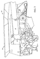
- FIGS 1 and 2 show an agricultural Combine harvester 10 having a supporting structure 12 engaged has means 14 located on the ground, which are from of the supporting structure 12 extend downwards.
- Such one Combine harvester is described in detail in US 6,285,198 the disclosure of which is incorporated by reference into the present Documents is included.
- the invention can be used on any other Types of combine harvesters are used, such as conventional ones Straw walker machines.
- a cutter 16 is used to Harvest crop and feed it to an inclined conveyor 18.
- the crop is one by the feeder 18
- Guide drum 20 supplied.
- the guide drum 20 guides the crop up through an inlet transition section 22 to one axial crop processing unit 24.
- the axial crop processing unit 24 is between the side walls of the combine 10 arranged and supported by them.
- the axial crop processing unit 24 comprises an axial one Rotor housing 26 and one arranged in the rotor housing 26 axial rotor 28.
- the harvested crop passes through the inlet transition section 22 into the rotor housing 26.
- the rotor 28 is with a loading section, a threshing section and equipped with a separating section.
- the rotor housing 26 has each a corresponding loading section, threshing section and Separating portion.
- Both crop processing sections of the rotor 28, the threshing section and the separating section are with good engagement assemblies fitted.
- the threshing section of the rotor housing 26 is equipped with a concave and the separating section with a rust. Grains and chaff released from the mat fall through the concave and the grate.
- the concave and the Rust prevents the passage of crop that is larger than grain or Kaff, in the cleaning system 34th
- the clean grain will then through an elevator 36 for clean grain one Fountain screw conveyor 38 supplied.
- the fountain screw conveyor 38 promotes the grain in a reservoir 40 in the kind of a grain tank.
- the elevator 36 for clean grain and the Fountain screw conveyors 38 include means for moving the clean grain from the grain bottom of the combine in the Storage container 40.
- the grain is conveyed through an unloading conveyor 57 in the form of a screw conveyor from the storage container 40 away.
- the discharge drum 46 conveys the straw to Combine 10 back.
- the operation of the Combine harvester 10 is operated from an operator's cab 48.
- discharge conveyor 56 and 58 in the form of Screw conveyors convey the grain to the side of the storage container 40, where it comes into contact with the discharge conveyor 57, which the clean grain through a vertical unloading tube 61 and a horizontal discharge tube 59 conducts.
- the discharge conveyor 57 includes a vertical section 57a that at least extends partially located within the unloading tube 61 right angle gear 57b, and a horizontal portion 57c within the discharge tube 59.
- the storage container 40 comprises a trough 60, which is a larger one Includes trough area 70 and a smaller trough area 72, which accommodate the horizontal unloading conveyors 56 and 58, respectively.
- the trough 60 is open to a loading housing or sump 64.
- the vertical portion 57a of the unloading conveyor 57 extends through the vertical tube 61 and into the sump 64. That through the horizontal unloading conveyors 56 and 58 horizontally through the Trough 60 conveyed grain is released into the sump 64 and by means of the vertical section 57a through the pipe 61 and by means of the horizontal section 57 c through the discharge tube 59 removed.
- the larger trough area 70 a front sloping wall 76 and a rear sloping wall 78.
- the smaller trough area 72 includes a rear inclined one Wall 82 that curves into rear sloping wall 78 of the larger trough area 70 passes over.
- the swamp 64 includes Sidewalls 84 that are substantially parallel to each other and extend vertically and essentially continuously to the inclined walls 78, 82 are attached. Only the left side wall 84 of the swamp 64 is visible in the figures, the right one Sidewall of the sump 64 has substantially the same shape as the left side wall 84.
- the unloading conveyors 56, 58 are driven by pinions 108, 110 driven.
- the discharge conveyor 57 is by a right angle gear 112 driven by a pinion 116 is driven.
- a chain drive assembly for turning pinion 108, 110, 116 is described in more detail in US 4,967,863 and in U.S. Patent Application 10/309977, the Disclosures by reference in the present documents be included.
- the sump 64 comprises one front sloping wall 118, a rear sloping wall 119 and an element 120 made of cast material for the screw conveyor.
- the Element 120 is attached to the inclined walls 118, 119.
- the front sloping wall 118 is on the front sloping wall 76 and the left side wall 84 and the right side wall of the Swamp 64 attached.
- the rear sloping wall 119 is on the rear sloping wall 82 and on the left side wall 84 and attached to the right side wall of the sump 64.
- the left and right side walls of the sump 64, the element 120 and the walls 118, 119 form an essentially closed sump Except for the drain openings described below. If below described sealing plug attached in the element 120 are, the sump 64 with the trough areas 70, 72 forms an im Essentially closed unit.
- the element 120 comprises pivot bearings 122, 124 for rotatable Inclusion of one with a horizontal axis of rotation Gear assembly 126 for right angle gear 112.
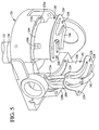
- the Element 120 also includes a pivot bearing 130 ( Figure 5) for supporting and rotatably holding a vertical shaft 132 of the screw conveyor 57.
- a gear 134 with a vertical axis is attached to shaft 132.
- a rotation of the gear 134 causes the screw conveyor 57 to rotate.
- Element 120 comprises two pairs of drain openings 170a, 170b, 172a, 172b, which drain water from the sump 64 and its emptying of grain and other plant material allow.
- the invention at least represents one and preferably two sealing plugs 180, 182 ready, each one or more bodies 194, 196, 204, 206 each having a size and shape that it allows them into an opening 170a, 170b, 172a, 172b insert and the bottom of element 120 and thus the swamp 64 effectively lock.
- Each opening 170a, 170b, 172a, 172b has a crescent shape Cross section and the corresponding body 194, 196, 204, 206 of Sealing plug 180, 182 has a corresponding one crescent-shaped horizontal cross-section.
- everyone Sealing plug 180, 182 comprises a grip element 190, 192, that extends from the undersides of adjacent bodies 194, 196, 204, 206 extends.
- Each body 194, 196, 204, 206 can be one length have that is essentially equal to the depth of each Opening 170a, 170b, 172a, 172b.
- Each plug 180, 182 can have a flange 220, 224 which on a lower surface 120a, 120b of the Elements 120 abuts when the bodies 194, 196, 204, 206 fully inserted into openings 170a, 170b, 172a, 182b are.
- Element 120 may be a variety of threaded
- Have holes 226 preferably in the form of blind holes and flanges 220, 224 may have a plurality of smooth holes 228 having the threaded holes 226 are aligned.
- a variety of fasteners 230 (in the form of wing screws) with washers 231 (from one of which is shown) can be in the smooth holes 228 inserted and with the threaded holes 226 in Be engaged to the plugs 180, 182 on to fix the element 120.
- FIGS. 7 and 8 represent the sealing plug 180
- the rear body 194 of the sealing plug 180 has strategically arranged cutouts 194a, 194b, which an impairment of the body 194 by the to Attach the element 100 to the wall 119 of the sump 64 (see. Figure 4) prevent serving fasteners.
- FIGS. 9 and 10 represent the sealing plug 182 front body 204 of the plug 182 has one strategically arranged cutout 204a, one Impairment of the body 194 by the to attach the Elements 100 on the wall 118 of the sump 64 (see FIG. 4) prevent serving fasteners.
- Each body 194, 196, 204, 206 is substantially hollow with an open lower end 250 and a closed upper end End 252.
- the hollow structure of the plug 180, 182 allows an elastic compression within the openings 170a, 170b, 172a, 172b, around the body 194, 196, 204, 206 better match the shape of the openings 170a, 170b, 172a, 172b allow.
- the hollow structure also allows easier casting the plug 180, 182.
- the sealing plugs 180, 182 are preferably made of one soft plastic built up with the bottom surface of the Elements 120 melts and a lockable cover of the Casting element 120 is unnecessary. Other plastic materials or other non-plastic materials can also be used.
- the plugs 180, 182 prevent material from entering the Openings 170a, 170b, 172a, 172b in element 120 form bridges.
- the plugs 180, 182 are with the existing one Element 120 geometry in many commercially available Combines from John Deere compatible.
Landscapes
- Life Sciences & Earth Sciences (AREA)
- Environmental Sciences (AREA)
- Threshing Machine Elements (AREA)
- Outside Dividers And Delivering Mechanisms For Harvesters (AREA)
- Packages (AREA)
Abstract
Description
- Fig. 1
- eine schematische Seitenansicht einer Erntemaschine, in der die vorliegende Erfindung verwirklicht ist,
- Fig. 2
- eine schematische Draufsicht auf die Erntemaschine aus Figur 1,
- Fig. 3
- eine vergrößerte, perspektivische Teilansicht des Vorratsbehälters der Erntemaschine aus Figur 1,
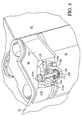
- Fig. 4
- eine von unten betrachtete vergrößerte, perspektivische Teilansicht des in Figur 3 gezeigten Vorratsbehälters,
- Fig. 5
- eine vergrößerte perspektivische Ansicht eines Elements für den Schneckenförderer mit Verschlussstopfen, die gerade eingesetzt werden,
- Fig. 6
- eine perspektivische Ansicht des Elements aus Figur 5 mit den vollständig eingesetzten Verschlussstopfen,
- Fig. 7
- eine perspektivische rückwärtige Ansicht eines Verschlussstopfens für das Element,
- Fig. 8
- eine perspektivische Ansicht des Verschlussstopfens aus Figur 7 von vorn,
- Fig. 9
- eine perspektivische Ansicht eines anderen Verschlussstopfens für das Element von vorn, und
- Fig. 10
- eine perspektivische Ansicht des Verschlussstopfens aus Figur 9 von hinten.
Claims (10)
- Kombination aus einem Vorratsbehälter (40) einer Erntemaschine (10) für geerntetes Erntegut, der eine als bodenseitige Ablauföffnung dienende Öffnung (170a, 170b, 172a, 172b) aufweist und einem Verschlussstopfen (180, 182), der in die Öffnung (170a, 170b, 172a, 172b) einsteckbar ist, um sie zu verschließen.
- Kombination nach Anspruch 1, dadurch gekennzeichnet, dass die Querschnitte der Öffnung (170a, 170b, 172a, 172b) und des Verschlussstopfens (180, 182) mondsichelförmig sind.
- Kombination nach Anspruch 1 oder 2, dadurch gekennzeichnet, dass der Verschlussstopfen (180, 182) an der Außenseite der Öffnung (170a, 170b, 172a, 172b) ein Griffelement (190, 192) aufweist.
- Kombination nach einem der Ansprüche 1 bis 3, dadurch gekennzeichnet, dass im Vorratsbehälter (40) zwei Öffnungen (170a, 170b, 172a, 172b) in Nachbarschaft zueinander angeordnet sind, und dass der Verschlussstopfen (180, 182) zwei den Öffnungen (170a, 170b, 172a, 172b) zugeordnete Körper (194, 196, 204, 206) aufweist.
- Kombination nach Anspruch 4, dadurch gekennzeichnet, dass das Griffelement (190, 192) eine Überbrückung zwischen den beiden Körpern (194, 196, 204, 206) bildet.
- Kombination nach einem der Ansprüche 1 bis 5, dadurch gekennzeichnet, dass der Verschlussstopfen (180, 182) einen Flansch (220, 224) aufweist, der an einer äußeren Oberfläche des Vorratsbehälters (40) anliegt, wenn der Verschlussstopfen (180, 182) vollständig in die Öffnung (170a, 170b, 172a, 172b) eingesetzt ist.
- Kombination nach Anspruch 6, dadurch gekennzeichnet, dass der Vorratsbehälter (40) eine mit Gewinde versehene Öffnung (226) aufweist, die mit einer Öffnung (228) im Flansch (220, 224) ausgerichtet ist, und dass ein Befestigungselement (230) sich durch die Öffnung (228) im Flansch (220, 224) erstreckt und mit dem Gewinde der Öffnung (226) im Vorratsbehälter (40) im Eingriff steht.
- Kombination nach einem der Ansprüche 1 bis 7, dadurch gekennzeichnet, dass die Länge des Verschlussstopfens (180, 182) zumindest näherungsweise mit der Tiefe der Öffnung (170a, 170b, 172a, 172b) übereinstimmt.
- Kombination nach einem der Ansprüche 1 bis 8, dadurch gekennzeichnet, dass die Öffnung (170a, 170b, 172a, 172b) in einem Element (120) am Boden des Vorratsbehälters (40) angebracht ist, wobei das Element (120) einen Entladeförderer (57) abstützt.
- Kombination nach einem der vorhergehenden Ansprüche, dadurch gekennzeichnet, dass der Verschlussstopfen (180, 182) aus elastischem Material aufgebaut ist.
Applications Claiming Priority (2)
| Application Number | Priority Date | Filing Date | Title |
|---|---|---|---|
| US10/309,976 US20040110550A1 (en) | 2002-12-04 | 2002-12-04 | Closure for a cleanout opening of a harvesting apparatus |
| US309976 | 2002-12-04 |
Publications (2)
| Publication Number | Publication Date |
|---|---|
| EP1425950A1 true EP1425950A1 (de) | 2004-06-09 |
| EP1425950B1 EP1425950B1 (de) | 2006-06-07 |
Family
ID=32312260
Family Applications (1)
| Application Number | Title | Priority Date | Filing Date |
|---|---|---|---|
| EP03027710A Expired - Lifetime EP1425950B1 (de) | 2002-12-04 | 2003-12-02 | Vorratsbehälter und Verschlussstopfen |
Country Status (8)
| Country | Link |
|---|---|
| US (1) | US20040110550A1 (de) |
| EP (1) | EP1425950B1 (de) |
| AR (1) | AR042269A1 (de) |
| AU (1) | AU2003257876A1 (de) |
| BR (1) | BR0305341A (de) |
| CA (1) | CA2448952C (de) |
| DE (1) | DE50303664D1 (de) |
| DK (1) | DK1425950T3 (de) |
Cited By (1)
| Publication number | Priority date | Publication date | Assignee | Title |
|---|---|---|---|---|
| EP3081070A1 (de) * | 2015-04-14 | 2016-10-19 | Deere & Company | Aussperrungsverschlussmechanismus für landwirtschaftliches fahrzeug |
Families Citing this family (6)
| Publication number | Priority date | Publication date | Assignee | Title |
|---|---|---|---|---|
| US10188856B1 (en) | 2011-12-07 | 2019-01-29 | Cyberonics, Inc. | Implantable device for providing electrical stimulation of cervical vagus nerves for treatment of chronic cardiac dysfunction |
| US8923964B2 (en) | 2012-11-09 | 2014-12-30 | Cyberonics, Inc. | Implantable neurostimulator-implemented method for enhancing heart failure patient awakening through vagus nerve stimulation |
| US9643008B2 (en) | 2012-11-09 | 2017-05-09 | Cyberonics, Inc. | Implantable neurostimulator-implemented method for enhancing post-exercise recovery through vagus nerve stimulation |
| US9452290B2 (en) | 2012-11-09 | 2016-09-27 | Cyberonics, Inc. | Implantable neurostimulator-implemented method for managing tachyarrhythmia through vagus nerve stimulation |
| US9643011B2 (en) | 2013-03-14 | 2017-05-09 | Cyberonics, Inc. | Implantable neurostimulator-implemented method for managing tachyarrhythmic risk during sleep through vagus nerve stimulation |
| CN119817221B (zh) * | 2025-01-17 | 2025-11-14 | 淮安兴岚科技有限公司 | 一种适用多种土壤的智能挖机耕作设备 |
Citations (5)
| Publication number | Priority date | Publication date | Assignee | Title |
|---|---|---|---|---|
| US3664525A (en) * | 1969-07-25 | 1972-05-23 | Massey Ferguson Gmbh | Rotating grain tank unloader |
| US4523690A (en) * | 1982-12-03 | 1985-06-18 | M & W Gear Company | Door operating mechanism for gravity type farm wagon |
| FR2581601A1 (fr) * | 1985-05-07 | 1986-11-14 | Audureau Sa | Perfectionnement apporte aux unites de pesages mobiles pour experimentations agricoles |
| EP0525441A1 (de) * | 1991-07-17 | 1993-02-03 | De Dissel Beheer B.V. | Transport- und Reinigungsvorrichtung für Futterfrüchte |
| US6285198B1 (en) * | 1995-09-01 | 2001-09-04 | Deere & Company | Grain moisture sensor |
Family Cites Families (15)
| Publication number | Priority date | Publication date | Assignee | Title |
|---|---|---|---|---|
| US1423464A (en) * | 1922-01-20 | 1922-07-18 | Shaw Specialty Co Inc | Stopper for hot-water bottles |
| US1900628A (en) * | 1931-08-27 | 1933-03-07 | American Car & Foundry Co | Tank dome closure |
| US1973442A (en) * | 1932-12-16 | 1934-09-11 | Nat Pressure Cooker Co | Pressure cooker |
| US2003460A (en) * | 1933-11-14 | 1935-06-04 | Eagle Mfg Co | Removable cap for cans or the like |
| US3181505A (en) * | 1963-04-09 | 1965-05-04 | Ollie C Walraven | Semi-automatic hog and calf feed dispenser |
| US3329447A (en) * | 1965-01-18 | 1967-07-04 | Gifford L Hitz | Self-energizing seal for high pressure flanged connections |
| US3472416A (en) * | 1968-05-29 | 1969-10-14 | Harvey Aluminum Inc | Pressure compensating resealable plug |
| US3935686A (en) * | 1974-04-08 | 1976-02-03 | General Motors Corporation | Vehicle drain hole plug |
| US4802812A (en) * | 1985-07-12 | 1989-02-07 | Simpson Iii Leland S | Apparatus for harvesting row crops |
| DE3838250C1 (de) * | 1988-11-11 | 1990-01-18 | Dr.Ing.H.C. F. Porsche Ag, 7000 Stuttgart, De | |
| US5086522A (en) * | 1990-06-21 | 1992-02-11 | Stofko Sr George D | Drain plug apparatus |
| US5161690A (en) * | 1992-01-21 | 1992-11-10 | Dynoplast A/S | Parallellepidepic transport container |
| US5287982A (en) * | 1993-05-20 | 1994-02-22 | Ho Lee Co., Ltd. | Structure for the external cap of a spout |
| US5498333A (en) * | 1994-06-02 | 1996-03-12 | Canther; David M. | Cover and lid with sealably enclosed gasket for swimming pool |
| US6539743B2 (en) * | 2001-03-13 | 2003-04-01 | Dippin′ Dots, Inc. | Transport assembly for transporting free flowing frozen product away from a cryogenic processor |
-
2002
- 2002-12-04 US US10/309,976 patent/US20040110550A1/en not_active Abandoned
-
2003
- 2003-10-24 AU AU2003257876A patent/AU2003257876A1/en not_active Abandoned
- 2003-11-12 CA CA002448952A patent/CA2448952C/en not_active Expired - Fee Related
- 2003-11-27 BR BR0305341-5A patent/BR0305341A/pt not_active Application Discontinuation
- 2003-12-02 DE DE50303664T patent/DE50303664D1/de not_active Expired - Fee Related
- 2003-12-02 AR ARP030104437A patent/AR042269A1/es active IP Right Grant
- 2003-12-02 DK DK03027710T patent/DK1425950T3/da active
- 2003-12-02 EP EP03027710A patent/EP1425950B1/de not_active Expired - Lifetime
Patent Citations (5)
| Publication number | Priority date | Publication date | Assignee | Title |
|---|---|---|---|---|
| US3664525A (en) * | 1969-07-25 | 1972-05-23 | Massey Ferguson Gmbh | Rotating grain tank unloader |
| US4523690A (en) * | 1982-12-03 | 1985-06-18 | M & W Gear Company | Door operating mechanism for gravity type farm wagon |
| FR2581601A1 (fr) * | 1985-05-07 | 1986-11-14 | Audureau Sa | Perfectionnement apporte aux unites de pesages mobiles pour experimentations agricoles |
| EP0525441A1 (de) * | 1991-07-17 | 1993-02-03 | De Dissel Beheer B.V. | Transport- und Reinigungsvorrichtung für Futterfrüchte |
| US6285198B1 (en) * | 1995-09-01 | 2001-09-04 | Deere & Company | Grain moisture sensor |
Cited By (2)
| Publication number | Priority date | Publication date | Assignee | Title |
|---|---|---|---|---|
| EP3081070A1 (de) * | 2015-04-14 | 2016-10-19 | Deere & Company | Aussperrungsverschlussmechanismus für landwirtschaftliches fahrzeug |
| US9510514B2 (en) | 2015-04-14 | 2016-12-06 | Deere & Company | Lockout closure mechanism for agricultural vehicle |
Also Published As
| Publication number | Publication date |
|---|---|
| AR042269A1 (es) | 2005-06-15 |
| DK1425950T3 (da) | 2006-10-02 |
| US20040110550A1 (en) | 2004-06-10 |
| BR0305341A (pt) | 2004-08-31 |
| DE50303664D1 (de) | 2006-07-20 |
| AU2003257876A1 (en) | 2004-06-24 |
| EP1425950B1 (de) | 2006-06-07 |
| CA2448952C (en) | 2009-03-17 |
| CA2448952A1 (en) | 2004-06-04 |
Similar Documents
| Publication | Publication Date | Title |
|---|---|---|
| DE60201993T2 (de) | Abschirmmittel für einen elevator einer landwirtschaftlichen erntemaschine | |
| EP0092805B1 (de) | Mähdrescher | |
| EP0522268B1 (de) | Axialabscheider | |
| DE69214072T2 (de) | Steinfangmulde für Mähdrescher | |
| DE2233018A1 (de) | Maehdrescher der axialflussbauart | |
| DE2336836A1 (de) | Erntemaschine | |
| EP1236391A1 (de) | Gutbearbeitungseinheit für einen Mähdrescher | |
| EP0933017A1 (de) | Rotationsförderer mit einem Rotationskörper und wenigstens einem Mitnehmer und Erntemaschine mit einem solchen Rotationsförderer | |
| DE102013226436B4 (de) | Schrägförderer für einen Mähdrescher | |
| DE3822689C2 (de) | ||
| DE1945401A1 (de) | Selbstfahrender Maehdrescher mit Axialdreschmaschine | |
| EP1425953B1 (de) | Erntemaschine mit Entladeförderer | |
| EP1425952B1 (de) | Reinigungseinrichtung für einen Vorratsbehälter einer Erntemaschine | |
| DE3319138A1 (de) | -axial-dresch- und trennanordnung fuer maehdrescher mit einer vorrichtung zum zerkleinern des strohs und zum ausbreiten des zerkleinerten strohs auf dem boden | |
| EP1425950B1 (de) | Vorratsbehälter und Verschlussstopfen | |
| EP1425951B1 (de) | Erntemaschine mit Entladeförderer | |
| DE3709242A1 (de) | Reinigungsvorrichtung fuer maehdrescher | |
| EP1425954B1 (de) | Reinigungseinrichtung für ein Entladerohr einer Erntemaschine | |
| DE102005060453A1 (de) | Maschine zur Ernte stängelartiger Pflanzen | |
| EP1354508B1 (de) | Axialabscheider mit Leitschiene | |
| EP0436755B1 (de) | Vorrichtung zum Reinigen und Schnitzeln von Rüben od. dgl. | |
| EP0109518B1 (de) | Schneckenfördereinrichtung | |
| EP1709868B1 (de) | Vorrichtung zum Mischen und Verteilen von Schüttgütern | |
| EP0151731B1 (de) | Rübenerntemaschine | |
| DE10232802A1 (de) | Erntemaschine |
Legal Events
| Date | Code | Title | Description |
|---|---|---|---|
| PUAI | Public reference made under article 153(3) epc to a published international application that has entered the european phase |
Free format text: ORIGINAL CODE: 0009012 |
|
| AK | Designated contracting states |
Kind code of ref document: A1 Designated state(s): AT BE BG CH CY CZ DE DK EE ES FI FR GB GR HU IE IT LI LU MC NL PT RO SE SI SK TR |
|
| AX | Request for extension of the european patent |
Extension state: AL LT LV MK |
|
| 17P | Request for examination filed |
Effective date: 20041209 |
|
| AKX | Designation fees paid |
Designated state(s): DE DK FR GB IT |
|
| GRAP | Despatch of communication of intention to grant a patent |
Free format text: ORIGINAL CODE: EPIDOSNIGR1 |
|
| GRAS | Grant fee paid |
Free format text: ORIGINAL CODE: EPIDOSNIGR3 |
|
| GRAA | (expected) grant |
Free format text: ORIGINAL CODE: 0009210 |
|
| AK | Designated contracting states |
Kind code of ref document: B1 Designated state(s): DE DK FR GB IT |
|
| REG | Reference to a national code |
Ref country code: GB Ref legal event code: FG4D Free format text: NOT ENGLISH |
|
| REF | Corresponds to: |
Ref document number: 50303664 Country of ref document: DE Date of ref document: 20060720 Kind code of ref document: P |
|
| GBT | Gb: translation of ep patent filed (gb section 77(6)(a)/1977) |
Effective date: 20060731 |
|
| REG | Reference to a national code |
Ref country code: DK Ref legal event code: T3 |
|
| ET | Fr: translation filed | ||
| PLBE | No opposition filed within time limit |
Free format text: ORIGINAL CODE: 0009261 |
|
| STAA | Information on the status of an ep patent application or granted ep patent |
Free format text: STATUS: NO OPPOSITION FILED WITHIN TIME LIMIT |
|
| 26N | No opposition filed |
Effective date: 20070308 |
|
| PGFP | Annual fee paid to national office [announced via postgrant information from national office to epo] |
Ref country code: DK Payment date: 20081230 Year of fee payment: 6 |
|
| PGFP | Annual fee paid to national office [announced via postgrant information from national office to epo] |
Ref country code: IT Payment date: 20081222 Year of fee payment: 6 |
|
| PGFP | Annual fee paid to national office [announced via postgrant information from national office to epo] |
Ref country code: DE Payment date: 20081120 Year of fee payment: 6 |
|
| PGFP | Annual fee paid to national office [announced via postgrant information from national office to epo] |
Ref country code: GB Payment date: 20081229 Year of fee payment: 6 |
|
| PGFP | Annual fee paid to national office [announced via postgrant information from national office to epo] |
Ref country code: FR Payment date: 20081217 Year of fee payment: 6 |
|
| REG | Reference to a national code |
Ref country code: DK Ref legal event code: EBP |
|
| GBPC | Gb: european patent ceased through non-payment of renewal fee |
Effective date: 20091202 |
|
| REG | Reference to a national code |
Ref country code: FR Ref legal event code: ST Effective date: 20100831 |
|
| PG25 | Lapsed in a contracting state [announced via postgrant information from national office to epo] |
Ref country code: FR Free format text: LAPSE BECAUSE OF NON-PAYMENT OF DUE FEES Effective date: 20091231 |
|
| PG25 | Lapsed in a contracting state [announced via postgrant information from national office to epo] |
Ref country code: DE Free format text: LAPSE BECAUSE OF NON-PAYMENT OF DUE FEES Effective date: 20100701 |
|
| PG25 | Lapsed in a contracting state [announced via postgrant information from national office to epo] |
Ref country code: GB Free format text: LAPSE BECAUSE OF NON-PAYMENT OF DUE FEES Effective date: 20091202 |
|
| PG25 | Lapsed in a contracting state [announced via postgrant information from national office to epo] |
Ref country code: DK Free format text: LAPSE BECAUSE OF NON-PAYMENT OF DUE FEES Effective date: 20100104 |
|
| PG25 | Lapsed in a contracting state [announced via postgrant information from national office to epo] |
Ref country code: IT Free format text: LAPSE BECAUSE OF NON-PAYMENT OF DUE FEES Effective date: 20091202 |