EP1425436B1 - Ölbeseitigungsvorrichtung zum reinigen von in form von coils vorliegenden rohren - Google Patents
Ölbeseitigungsvorrichtung zum reinigen von in form von coils vorliegenden rohren Download PDFInfo
- Publication number
- EP1425436B1 EP1425436B1 EP02772046A EP02772046A EP1425436B1 EP 1425436 B1 EP1425436 B1 EP 1425436B1 EP 02772046 A EP02772046 A EP 02772046A EP 02772046 A EP02772046 A EP 02772046A EP 1425436 B1 EP1425436 B1 EP 1425436B1
- Authority
- EP
- European Patent Office
- Prior art keywords
- gas
- connection head
- line
- gas supply
- supply line
- Prior art date
- Legal status (The legal status is an assumption and is not a legal conclusion. Google has not performed a legal analysis and makes no representation as to the accuracy of the status listed.)
- Expired - Lifetime
Links
Images

Classifications
-
- B—PERFORMING OPERATIONS; TRANSPORTING
- B21—MECHANICAL METAL-WORKING WITHOUT ESSENTIALLY REMOVING MATERIAL; PUNCHING METAL
- B21C—MANUFACTURE OF METAL SHEETS, WIRE, RODS, TUBES, PROFILES OR LIKE SEMI-MANUFACTURED PRODUCTS OTHERWISE THAN BY ROLLING; AUXILIARY OPERATIONS USED IN CONNECTION WITH METAL-WORKING WITHOUT ESSENTIALLY REMOVING MATERIAL
- B21C43/00—Devices for cleaning metal products combined with or specially adapted for use with machines or apparatus provided for in this subclass
-
- C—CHEMISTRY; METALLURGY
- C21—METALLURGY OF IRON
- C21D—MODIFYING THE PHYSICAL STRUCTURE OF FERROUS METALS; GENERAL DEVICES FOR HEAT TREATMENT OF FERROUS OR NON-FERROUS METALS OR ALLOYS; MAKING METAL MALLEABLE, e.g. BY DECARBURISATION OR TEMPERING
- C21D9/00—Heat treatment, e.g. annealing, hardening, quenching or tempering, adapted for particular articles; Furnaces therefor
- C21D9/08—Heat treatment, e.g. annealing, hardening, quenching or tempering, adapted for particular articles; Furnaces therefor for tubular bodies or pipes
-
- C—CHEMISTRY; METALLURGY
- C23—COATING METALLIC MATERIAL; COATING MATERIAL WITH METALLIC MATERIAL; CHEMICAL SURFACE TREATMENT; DIFFUSION TREATMENT OF METALLIC MATERIAL; COATING BY VACUUM EVAPORATION, BY SPUTTERING, BY ION IMPLANTATION OR BY CHEMICAL VAPOUR DEPOSITION, IN GENERAL; INHIBITING CORROSION OF METALLIC MATERIAL OR INCRUSTATION IN GENERAL
- C23G—CLEANING OR DE-GREASING OF METALLIC MATERIAL BY CHEMICAL METHODS OTHER THAN ELECTROLYSIS
- C23G5/00—Cleaning or de-greasing metallic material by other methods; Apparatus for cleaning or de-greasing metallic material with organic solvents
-
- C—CHEMISTRY; METALLURGY
- C21—METALLURGY OF IRON
- C21D—MODIFYING THE PHYSICAL STRUCTURE OF FERROUS METALS; GENERAL DEVICES FOR HEAT TREATMENT OF FERROUS OR NON-FERROUS METALS OR ALLOYS; MAKING METAL MALLEABLE, e.g. BY DECARBURISATION OR TEMPERING
- C21D1/00—General methods or devices for heat treatment, e.g. annealing, hardening, quenching or tempering
- C21D1/74—Methods of treatment in inert gas, controlled atmosphere, vacuum or pulverulent material
Definitions
- the invention relates to an oil removal device for cleaning existing in the form of coils tubes with a tube receiving and heating furnace with or without associated cooling zone and a gas guide means for introducing and discharging purge gas into the tubes or from the tubes, wherein the gas supply means for detachable, sealed connection with a gas supply line on the one hand and a gas discharge on the other.
- a serious disadvantage of the device described results from the separately arranged, independent Gaszu Operations- and gas discharge connections.
- the tightness of these compounds is determined by the contact pressure of the connecting device. At high contact pressure there is a risk that the support frame is moved or deformed by the introduced via the connecting means mechanical forces within the furnace chamber, so that leaks may occur.
- Object of the present invention is to provide a generic oil removal device, which allows easy and gas-tight connection of the coils to the gas supply device.
- This object is achieved in a device of the type described above according to the invention in that both ends of each tube are connected separately to one and the same connection head, which has a Gaseinlass- and a gas outlet axially aligned therewith and that the end of the gas supply line and the gas discharge line facing each other and at the same time be sealingly connected to the gas inlet opening and gas outlet opening.
- the gas discharge line serves as a counter holder for receiving the mechanical contact pressure of the gas supply line, so that Gasab Operationss- and gas supply line the connection head between them pinch, so that slipping of the coil or the frame due to the mechanical forces of Gaszu- and gas removal is thus excluded.
- connection head is rigidly integrated or integrated in the frame, which serves to receive superimposed coils.
- this connection head is positioned by positioning the frame relative to the furnace chamber and fixed the frame in its relative position to the furnace chamber when the connection to the gas supply and gas discharge is established.
- a frame outside the furnace chamber can be equipped with several coils and then moved for treatment in the furnace chamber.
- the device according to the invention can furthermore be designed in such a way that the two ends of a coil are separately connected in a gas-conducting and gas-discharging manner via guide tubes connected to the frame, so that a firm connection between the connection head and a gas distribution system is provided.
- the device according to the invention can furthermore be designed such that the two tube ends of each coil are each connected via a flexible connecting piece to the gas-conducting and gas-deflecting guide tube.
- the device according to the invention can furthermore be designed such that the gas supply line and the gas discharge line are mounted in a straight line until they abut the gas inlet opening or the gas outlet opening and back, at least with their sections adjacent to the connection head.
- the connecting pieces of the gas supply and gas discharge line adjoining the connection head only have to perform a simple rectilinear movement in order to connect to the connection head.
- the device according to the invention can furthermore be designed such that the gas supply line and the gas discharge line can be moved at least with their section adjacent to the connection head along a curved path until it contacts the gas inlet opening or the gas outlet opening and back.
- the adjoining the connection head fittings of the gas supply line and gas discharge line must then be moved only along the curved path to make a gas-tight connection with the connection head.
- the device according to the invention can furthermore be designed so that the gas supply line and the gas discharge line are pneumatically or hydraulically driven in their movement. By driving the connecting pieces of the gas supply and gas discharge line thus necessary for a gas-tight connection contact pressure of the connecting pieces can be applied to the connection head.
- the device according to the invention can furthermore be designed so that the gas supply line and the gas discharge line at their connection head adjacent sections are pivotally mounted to accommodate any tolerances in the meeting of gas line and connection head. As a result, the seal on the connection head in the oven chamber can be made even more reliable.
- the device according to the invention can furthermore be designed such that the gas supply line and the gas discharge line are designed to be axially flexible at their portions adjacent to the connection head. This ensures that the tolerances occurring in the positioning of the connection head in the furnace chamber are compensated in the axial direction, without the frame is displaced by the applied contact pressure.
- the device according to the invention may be designed such that the discharge gas guide tube has a plurality of separate channels, each communicating with the outlet of a tube of a particular coil.
- the guide tube for the gases to be supplied may have a plurality of separate channels, each communicating with an inlet of a tube of a specific coil. This allows a measurement and control of the gas flow through a specific coil.
- the frame 1 (Fig. 1) has superimposed essays 2, each having a space 3 for receiving the coils.
- a connection head 4 with a gas inlet opening 5 and an opposing gas outlet opening 6 is integrated.
- the adjoining the connection head 4 ends 7 and 8 of the gas supply 15 and gas discharge 16 are shown in dashed lines.
- the gas inlet opening 5 and gas outlet opening 6 are aligned axially and opposite to the openings 5, 6 of the connection head 4. It can clearly be seen that the openings of the connecting pieces 7, 8 of the gas supply 15 and gas discharge line 16 and the inlet and outlet openings 5, 6 of the connection head 4 are aligned on an axis, so that the connecting pieces 7, 8 are to be moved along the axis, to effect a connection with the connection head 4.
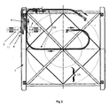
- Figure 2 shows the lower part of the frame 1, in which the connection head 4 is integrated such that it consists of a provided for the gas supply fitting 11 and provided for the gas discharge fitting 12.
- These fittings 11 and 12 are fixedly connected to the frame 1 and on the other hand take on the also firmly connected to the frame 1 guide tubes 9.
- the flexible connecting pieces 10 are connected, which conduct the gas in a dashed lines indicated coil 13. Furthermore, it can be seen that the openings of the connecting pieces 11, 12 and the openings of the connecting pieces 7,8 of the gas supply 15 and gas discharge 16 are aligned along an axis.
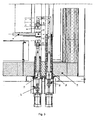
- Figure 3 shows a section through the furnace wall 14, through the Gaszu instruments- 15 and gas discharge line 16 with the attached fittings 7 and 8 and through the connection head 4 with the associated fittings 11 and 12.
- the flow of gas begins here with the feed 17 in the gas supply 15. Subsequently, the gas is passed through the connecting pieces 7 and 11 in the guide tubes 9. From there it is fed into and out of the coils and then guided via the guide tubes 9, the connecting pieces 12 in the gas discharge line 16 until it is discharged through the outlet 18.
Landscapes
- Chemical & Material Sciences (AREA)
- Engineering & Computer Science (AREA)
- Mechanical Engineering (AREA)
- Metallurgy (AREA)
- Organic Chemistry (AREA)
- Materials Engineering (AREA)
- Physics & Mathematics (AREA)
- General Chemical & Material Sciences (AREA)
- Chemical Kinetics & Catalysis (AREA)
- Thermal Sciences (AREA)
- Crystallography & Structural Chemistry (AREA)
- Cleaning In General (AREA)
- Cleaning And De-Greasing Of Metallic Materials By Chemical Methods (AREA)
- Joints Allowing Movement (AREA)
- Heat Treatment Of Articles (AREA)
- Furnace Details (AREA)
- Waste-Gas Treatment And Other Accessory Devices For Furnaces (AREA)
Description
- Die Erfindung betrifft eine Ölbeseitigungsvorrichtung zum Reinigen von in Form von Coils vorliegenden Rohren mit einem die Rohre aufnehmenden und aufheizenden Ofen mit oder ohne zugeordneter Kühlzone und einer Gasführungseinrichtung zur Einleitung und Abführung von Spülgas in die Rohre bzw. aus den Rohren, wobei die Gaszuführungseinrichtung Mittel zur lösbaren, dichten Verbindung mit einer Gaszuführungsleitung einerseits bzw. einer Gasableitung andererseits hat.
- Aus der Schrift EP0659907 B1 ist eine gattungsgemäße Ölbeseitigungsvorrichtung bekannt. Bei der dort beschriebenen Vorrichtung wird das Coil in einem Ofenraum erhitzt und zur Reinigung des Inneren eines Rohres wird über eine Gaszuführungseinrichtung ein Gas in dieses ein- und ausgeleitet. Der Anschluss der Enden des zu reinigenden Rohres erfolgt dabei über zwei Verbindungsstücke, die jeweils an einer Zug- und Druckstange angebracht sind und unabhängig voneinander und an gegenüberliegenden Seiten des Ofenraumes an die entsprechenden Gegenstücke heranbewegt werden. Diese Verbindungseinrichtung ist über ein Universalgelenk mit der Zug- und Druckstange verbunden, so dass eine gasdichte Verbindung auch in dem Fall erreicht werden kann, dass das Haltegestell des Coils leicht verdreht in dem Ofenraum positioniert ist und die Anschlussenden der Verbindungseinrichtung nicht parallel zueinander stehen.
- Ein gravierender Nachteil der beschriebenen Vorrichtung ergibt sich aus den voneinander getrennt angeordneten, voneinander unabhängigen Gaszuführungs- und Gasabführungsverbindungen. Die Dichtigkeit dieser Verbindungen wird durch den Anpressdruck der Verbindungseinrichtung bestimmt. Bei hohem Anpressdruck besteht damit die Gefahr, dass das Tragegestell durch die über die Verbindungseinrichtung eingeleiteten mechanischen Kräfte innerhalb des Ofenraumes verschoben oder verformt wird, so dass Undichtigkeiten auftreten können.
- Aufgabe der vorliegenden Erfindung ist es, eine gattungsgemäße Ölbeseitigungsvorrichtung zu schaffen, die den einfachen und gasdichten Anschluss der Coils an die Gaszuführungseinrichtung ermöglicht.
Diese Aufgabe wird bei einer Vorrichtung der eingangs beschriebenen Art erfindungsgemäß dadurch gelöst, dass beide Enden jedes Rohres separat an ein und denselben Anschlusskopf angeschlossen sind, der eine Gaseinlass- und eine damit axial ausgerichtete Gasauslassöffnung aufweist und dass das Ende der Gaszuführungsleitung und der Gasabführungsleitung einander entgegengerichtet und gleichzeitig mit der Gaseinlassöffnung und Gasauslassöffnung in Dichtverbindung bewegbar sind. - Dadurch, dass die Einlassöffnung entgegengesetzt und axial ausgerichtet zur Auslassöffnung angeordnet ist und beide Öffnungen in ein und demselben Anschlusskopf nahe beieinander liegend angeordnet sind, dient die Gasabführungsleitung als Gegenhalter zur Aufnahme der mechanischen Anpresskraft der Gaszuführungsleitung, so dass Gasabführungs- und Gaszuführungsleitung den Anschlusskopf zwischen sich einklemmen, so dass ein Verrutschen des Coils oder des Gestells aufgrund der mechanischen Kräfte der Gaszu- und Gasabführung damit ausgeschlossen ist.
- Die erfindungsgemäße Vorrichtung kann auch so ausgebildet sein, dass der Anschlusskopf in das Gestell, welches zur Aufnahme von übereinanderliegenden Coils dient, starr eingebunden oder integriert ist. Damit wird dieser Anschlusskopf durch Positionierung des Gestells relativ zum Ofenraum positioniert und das Gestell in seiner relativen Position zum Ofenraum fixiert, wenn die Verbindung zur Gaszuführung- und Gasabführung hergestellt ist. Weiterhin kann ein derartiges Gestell außerhalb des Ofenraums mit mehreren Coils bestückt und anschließend zur Behandlung in den Ofenraum bewegt werden.
- Die erfindungsgemäße Vorrichtung kann femer so ausgebildet sein, dass die beiden Enden eines Coils separat über mit dem Gestell verbundene Leitrohre gaszuleitend und gasableitend verbunden sind, so dass damit eine feste Verbindung zwischen dem Anschlusskopf und einem Gasverteilungssystem gegeben ist.
- Die erfindungsgemäße Vorrichtung kann femer so ausgebildet sein, dass die beiden Rohrenden jedes Coils über je ein flexibles Verbindungsstück mit dem gaszuleitenden und gasableitenden Leitrohr verbunden sind. Damit ist der Anschluss eines Coils an die Gaszuleitung und Gasableitung erheblich vereinfacht, da durch die flexiblen Verbindungsstücke geometrische Toleranzen der äußeren Form des Coils ausgeglichen werden können.
- Die erfindungsgemäße Vorrichtung kann femer so ausgebildet sein, dass die Gaszuführungsleitung und die Gasabführungsleitung zumindest mit ihren dem Anschlusskopf benachbarten Abschnitten geradlinig fluchtend bis zur Anlage an der Gaseinlassöffnung bzw. der Gasauslassöffnung und zurück bewegbar gelagert sind. Somit müssen die an den Anschlusskopf anschließenden Anschlussstücke der Gaszuführungs- und Gasabführungsleitung nur eine einfache geradlinige Bewegung ausführen, um an den Anschlusskopf anzuschließen.
- Die erfindungsgemäße Vorrichtung kann femer so ausgebildet sein, dass die Gaszuführungs- und die Gasabführungsleitung zumindest mit ihren dem Anschlusskopf benachbarten Abschnitt längs einer gewölbten Bahn bis zur Anlage an der Gaseinlassöffnung bzw. der Gasauslassöffnung und zurück bewegbar sind. Die an den Anschlusskopf anschließenden Anschlussstücke der Gaszuführungsleitung und Gasabführungsleitung müssen dann nur noch entlang der gewölbten Bahn bewegt werden, um eine gasdichte Verbindung mit dem Anschlusskopf herzustellen.
- Die erfindungsgemäße Vorrichtung kann femer so ausgebildet sein, dass die Gaszuführungsleitung und die Gasabführungsleitung in ihrer Bewegung pneumatisch oder hydraulisch angetrieben sind. Durch den Antrieb der Anschlussstücke der Gaszuführungs- und Gasabführungsleitung kann somit der für eine gasdichte Verbindung notwendige Anpressdruck der Anschlussstücke auf den Anschlusskopf aufgebracht werden.
- Die erfindungsgemäße Vorrichtung kann femer so ausgebildet sein, dass die Gaszuführungsleitung und die Gasabführungsleitung an ihren dem Anschlusskopf benachbarten Abschnitten zur Anpassung an etwaige Toleranzen bei dem Aufeinandertreffen von Gasleitung und Anschlusskopf schwenkbar gelagert sind. Hierdurch kann die Abdichtung am Anschlusskopf im Ofenraum noch zuverlässiger gestaltet werden.
- Die erfindungsgemäße Vorrichtung kann femer so ausgebildet sein, dass die Gaszuführungsleitung und die Gasabführungsleitung an ihren dem Anschlusskopf benachbarten Abschnitten axial flexibel ausgebildet sind. Hierdurch wird erreicht, dass die bei der Positionierung des Anschlusskopfes im Ofenraum auftretenden Toleranzen in axialer Richtung ausgeglichen werden, ohne dass das Gestell durch die einwirkenden Anpresskräfte verschoben wird.
- Die erfindungsgemäße Vorrichtung kann schließlich so ausgebildet sein, dass das Leitrohr für die abführenden Gase mehrere voneinander getrennte Kanäle aufweist, die jeweils mit dem Auslass eines Rohres eines bestimmten Coils kommunizieren. Umgekehrt kann ebenso das Leitrohr für die zuzuführenden Gase mehrere voneinander getrennte Kanäle aufweisen, die jeweils mit einem Einlass eines Rohres eines bestimmten Coils kommunizieren. Dies ermöglicht eine Messung und Regelung des Gasdurchflusses durch ein bestimmtes Coil.
- Nachfolgend wird nun eine Ausführungsform der erfindungsgemäßen Vorrichtung anhand von Zeichnungen beschrieben. Es zeigt:
- Fig. 1:
- Vertikaler Schnitt durch ein Gestell zur Aufnahme mehrerer Coils mit einem in das Gestell integrierten Anschlusskopf
- Fig. 2:
- Horizontaler Schnitt durch das Gestell mit integriertem Anschlusskopf
- Fig. 3:
- Schnitt durch die Ofenwand, die Gaszuführungs- und Gasabführungsleitung und das Gestell mit integriertem Anschlusskopf
- Das Gestell 1 (Fig. 1) hat übereinander angeordnete Aufsätze 2, die jeweils einen Raum 3 zur Aufnahme der Coils haben. In das Gestell 1 ist ein Anschlusskopf 4 mit einer Gaseinlassöffnung 5 und einer entgegengerichteten Gasauslassöffnung 6 integriert. Die an den Anschlusskopf 4 anschließenden Enden 7 und 8 der Gaszuführung 15 und Gasableitung 16 sind gestrichelt dargestellt. Die Gaseinlassöffnung 5 und Gasauslassöffnung 6 sind axial und entgegengesetzt zu den Öffnungen 5, 6 des Anschlusskopfes 4 ausgerichtet. Deutlich erkennbar ist, dass die Öffnungen der Anschlussstücke 7, 8 der Gaszuführung 15 und Gasabführungsleitung 16 und die Einlass- und Auslassöffnung 5, 6 des Anschlusskopfes 4 auf einer Achse ausgerichtet sind, so dass die Anschlussstücke 7, 8 entlang der Achse zu bewegen sind, um eine Verbindung mit dem Anschlusskopf 4 zu bewirken.
- Figur 2 zeigt den unteren Teil des Gestells 1, in den der Anschlusskopf 4 derart integriert ist, dass der aus einem für die Gaszuführung vorgesehenen Anschlussstück 11 und einem für die Gasabführung vorgesehenen Anschlussstück 12 besteht. Diese Anschlussstücke 11 und 12 sind fest mit dem Gestell 1 verbunden und nehmen andererseits die ebenfalls mit dem Gestell 1 fest verbundenen Leitrohre 9 auf. An diese Leitrohre 9 sind die flexiblen Verbindungsstücke 10 angeschlossen, die das Gas in ein gestrichelt angedeutetes Coil 13 leiten. Weiterhin ist zu erkennen, dass die Öffnungen der Anschlussstücke 11, 12 und die Öffnungen der Anschlussstücke 7,8 der Gaszuführung 15 und Gasabführung 16 entlang einer Achse ausgerichtet sind.
- Figur 3 zeigt einen Schnitt durch die Ofenwand 14, durch die Gaszuführungs- 15 und Gasabführungsleitung 16 mit den daran angebrachten Anschlussstücken 7 und 8 und durch den Anschlusskopf 4 mit den zugehörigen Anschlussstücken 11 und 12. Der Fluss des Gases beginnt hier mit der Zuführung 17 in die Gaszuführung 15. Anschließend wird das Gas durch die Anschlussstücke 7 und 11 in die Leitrohre 9 geleitet. Von dort wird es in die Coils ein- und ausgeleitet und anschließend über die Leitrohre 9, die Anschlussstücke 12 in die Gasabfuhrleitung 16 geführt bis es durch die Abführung 18 abgeführt wird. Ebenso wie in den Figuren 1 und 2 wird hier deutlich, dass die Öffnungen der Anschlussstücke 7, 8 der Gaszuführung 15 und Gasabführung 16 mit den Öffnungen der Anschlussstücke 11, 12 des Anschlusskopfes 4 längs einer gemeinsamen Achse ausgerichtet sind, so dass die Gaszuführungsleitung 15 und die Gasabführungsleitung 16 entlang dieser Achse zu bewegen sind, um einen gasdichten Anschluss über die Anschlussstücke 7, 8, 11 und 12 zu erreichen. Die für den Ausgleich von Toleranzen notwendige axiale Flexibilität der Gaszuführung 15 und Gasabführung 16 sowie die schwenkbare Lagerung der Anschlussstücke 7, 8 sind durch die Elemente 19 angedeutet.
-
- 1
- Gestell
- 2
- stapelbarer Aufsatz mit Raum zur Aufnahme eines Coils
- 3
- Raum zur Aufnahme eines Coils
- 4
- Anschlusskopf
- 5
- Einlassöffnung des Anschlusskopfes
- 6
- Auslassöffnung des Anschlusskopfes
- 7
- Anschlussstück der Gaszuführung
- 8
- Anschlussstück der Gasabführung
- 9
- Leitrohre
- 10
- Flexibles Verbindungsstück
- 11
- Anschlussstück (Einlass) des Anschlusskopfes
- 12
- Anschlussstück (Auslass) des Anschlusskopfes
- 13
- Coils
- 13a
- Rohrende eines Coils
- 14
- Ofenwand
- 15
- Gaszuführungsleitung
- 16
- Gasabführungsleitung
- 17
- Zuführung Schutzgas
- 18
- Abführung Schutzgas
- 19
- Flexibles Verbindungselement
Claims (10)
- Ölbeseitigungsvorrichtung zum Reinigen von in Form von Coils (13) vorliegenden Rohren mit einem die Rohre aufnehmenden und aufheizenden Ofen mit oder ohne zugeordnete Kühlzone und einer Gasführungseinrichtung (15, 16) zur Einleitung und Abführung von Spülgas in die Rohre bzw. aus den Rohren, wobei die Gasführungseinrichtung Mittel zur lösbaren, dichten Verbindung mit einer Gaszuführungsleitung (15) einerseits bzw. einer Gasableitung (16) andererseits hat,
dadurch gekennzeichnet,
dass ein Anschlusskopf (4) vorgesehen ist an dem beide Enden jedes Rohres separat kopf (4) angeschliessbar sind,
der eine Gaseinlass- (5) und eine damit axial ausgerichtete Gasauslassöffnung (6) aufweist und
dass das Ende (7) der Gaszuführungsleitung (15) und das Ende (8) der Gasabführungsleitung (16) einander entgegen gerichtet und gleichzeitig mit der Gaseinlassöffnung bzw. der Gasauslassöffnung in Dichtverbindung bewegbar sind. - Vorrichtung nach Anspruch 1, dadurch gekennzeichnet, dass der Anschlusskopf (4) in ein relativ zum Ofen bewegbares Gestell (1) zur Aufnahme mehrerer übereinander angeordneter Coils (13) integriert ist.
- Vorrichtung nach Anspruch 2, dadurch gekennzeichnet, dass die beiden Enden (13a) jedes Rohres (13) separat über mit dem Gestell verbundene Leitrohre (9) gaszuleitend bzw. gasableitend mit dem Anschlusskopf (4) verbunden sind.
- Vorrichtung nach Anspruch 3, dadurch gekennzeichnet, dass die beiden Rohrenden (13a) jedes Coils (13) über je ein flexibles Verbindungsstück (10) mit dem gaszu- bzw. gasableitenden Leitrohr (9) verbunden sind.
- Vorrichtung nach einem der vorhergehenden Ansprüche, dadurch gekennzeichnet, dass die Gaszuführungsleitung (15) und die Gasabführungsleitung (16) zumindest mit ihren dem Anschlusskopf (4) benachbarten Abschnitten (7, 8) geradlinig fluchtend bis zur Anlage an der Gaseinlassöffnung (5) bzw. der Gasauslassöffnung (6) und zurück bewegbar gelagert sind.
- Vorrichtung nach einem der Ansprüche 1 bis 4, dadurch gekennzeichnet, dass die Gaszuführungs- (15) und die Gasabführungsleitung (16) zumindest mit ihren dem Anschlusskopf (4) benachbarten Abschnitt (7, 8) längs einer gewölbten Bahn bis zur Anlage an der Gaseinlassöffnung (7) bzw. der Gasauslassöffnung (8) und zurück bewegbar sind.
- Vorrichtung nach einem der vorhergehenden Ansprüche, dadurch gekennzeichnet, dass die Gaszuführungsleitung und die Gasabführungsleitung in ihrer Bewegung pneumatisch oder hydraulisch angetrieben sind.
- Vorrichtung nach einem der vorhergehenden Ansprüche, dadurch gekennzeichnet, dass die Gaszuführungsleitung und die Gasabführungsleitung an ihren dem Anschlusskopf benachbarten Abschnitten zur Anpassung an etwaige Toleranzen in dem Aufeinandertreffen von Gasleitung und Anschlusskopf schwenkbar gelagert sind.
- Vorrichtung nach einem der vorhergehenden Ansprüche, dadurch gekennzeichnet, dass die Gaszuführungsleitung (15) und die Gasabführungsleitung (16) an ihren dem Anschlusskopf benachbarten Abschnitten (7, 8) axial flexibel ausgebildet sind.
- Vorrichtung nach einem der Ansprüche 2 bis 9, dadurch gekennzeichnet, dass das Leitrohr (9) für die abzuführenden Gase mehrere voneinander getrennte Kanäle aufweist, die jeweils mit dem Auslass eines Rohres eines bestimmten Coils (13) kommunizieren.
Applications Claiming Priority (3)
| Application Number | Priority Date | Filing Date | Title |
|---|---|---|---|
| DE10144509 | 2001-09-10 | ||
| DE10144509A DE10144509C1 (de) | 2001-09-10 | 2001-09-10 | Ölbeseitigungsvorrichtung zum Reinigen von in Form von Coils vorliegenden Rohren |
| PCT/DE2002/003288 WO2003025250A1 (de) | 2001-09-10 | 2002-09-06 | Ölbeseitigungsvorrichtung zum reinigen von in form von coils vorliegenden rohren |
Publications (2)
| Publication Number | Publication Date |
|---|---|
| EP1425436A1 EP1425436A1 (de) | 2004-06-09 |
| EP1425436B1 true EP1425436B1 (de) | 2006-05-17 |
Family
ID=7698492
Family Applications (1)
| Application Number | Title | Priority Date | Filing Date |
|---|---|---|---|
| EP02772046A Expired - Lifetime EP1425436B1 (de) | 2001-09-10 | 2002-09-06 | Ölbeseitigungsvorrichtung zum reinigen von in form von coils vorliegenden rohren |
Country Status (11)
| Country | Link |
|---|---|
| US (1) | US6862818B2 (de) |
| EP (1) | EP1425436B1 (de) |
| JP (1) | JP2005502477A (de) |
| CN (1) | CN1240875C (de) |
| AT (1) | ATE326560T1 (de) |
| BR (1) | BR0205977A (de) |
| CA (1) | CA2427999C (de) |
| DE (2) | DE10144509C1 (de) |
| MX (1) | MXPA03004681A (de) |
| RU (1) | RU2261941C2 (de) |
| WO (1) | WO2003025250A1 (de) |
Families Citing this family (4)
| Publication number | Priority date | Publication date | Assignee | Title |
|---|---|---|---|---|
| US8309231B2 (en) * | 2006-05-31 | 2012-11-13 | Usg Interiors, Llc | Acoustical tile |
| US20130112227A1 (en) * | 2011-11-07 | 2013-05-09 | Baker Hughes Incorporated | Elimination of hydraulic fluid contamination through internal bright annealing |
| US8857026B2 (en) * | 2012-05-06 | 2014-10-14 | Yongli Yang | Integral remanufacturing process of discarded oil pipe |
| CN103447747B (zh) * | 2013-09-06 | 2016-01-20 | 潍柴动力(潍坊)再制造有限公司 | 高压油管的再制造方法 |
Family Cites Families (6)
| Publication number | Priority date | Publication date | Assignee | Title |
|---|---|---|---|---|
| SU490874A1 (ru) * | 1974-04-29 | 1975-11-05 | Ленинградское Отделение Всесоюзного Научно-Исследовательского И Проектного Института | Способ подогрева и очистки от масла металлической стружки |
| SU705007A1 (ru) * | 1977-04-18 | 1979-12-25 | Липецкое Отделение Государственного Ордена Трудового Красного Знамени Союзного Института По Проектированию Агрегатов Сталелитейного И Прокатного Производства Для Черной Металлургии | Устройство дл обезжиривани и прокалки металлической стружки |
| JP2615719B2 (ja) * | 1987-12-21 | 1997-06-04 | 大同特殊鋼株式会社 | パイプコイル光輝焼鈍方法およびパイプ内パージング装置 |
| EP0659907B1 (de) * | 1993-11-11 | 1999-07-07 | Daidotokushuko Kabushiki Kaisha | Vorrichtung zur Beseitigung von Öl von aufwickelbare Röhren |
| JPH07173523A (ja) * | 1993-12-16 | 1995-07-11 | Furukawa Electric Co Ltd:The | パイプコイルの熱処理用トレー |
| CA2402028C (en) * | 2002-09-09 | 2004-11-02 | Ipsco Inc. | Apparatus for cleaning a coiler furnace drum |
-
2001
- 2001-09-10 DE DE10144509A patent/DE10144509C1/de not_active Expired - Fee Related
-
2002
- 2002-09-06 US US10/416,760 patent/US6862818B2/en not_active Expired - Fee Related
- 2002-09-06 CN CNB028031113A patent/CN1240875C/zh not_active Expired - Fee Related
- 2002-09-06 AT AT02772046T patent/ATE326560T1/de active
- 2002-09-06 MX MXPA03004681A patent/MXPA03004681A/es unknown
- 2002-09-06 BR BR0205977-0A patent/BR0205977A/pt not_active IP Right Cessation
- 2002-09-06 EP EP02772046A patent/EP1425436B1/de not_active Expired - Lifetime
- 2002-09-06 JP JP2003530018A patent/JP2005502477A/ja active Pending
- 2002-09-06 CA CA002427999A patent/CA2427999C/en not_active Expired - Fee Related
- 2002-09-06 RU RU2003113560/14A patent/RU2261941C2/ru not_active IP Right Cessation
- 2002-09-06 WO PCT/DE2002/003288 patent/WO2003025250A1/de not_active Ceased
- 2002-09-06 DE DE50206830T patent/DE50206830D1/de not_active Expired - Lifetime
Also Published As
| Publication number | Publication date |
|---|---|
| DE10144509C1 (de) | 2003-06-18 |
| US6862818B2 (en) | 2005-03-08 |
| US20040020071A1 (en) | 2004-02-05 |
| EP1425436A1 (de) | 2004-06-09 |
| DE50206830D1 (de) | 2006-06-22 |
| WO2003025250A1 (de) | 2003-03-27 |
| CA2427999C (en) | 2008-11-18 |
| ATE326560T1 (de) | 2006-06-15 |
| CA2427999A1 (en) | 2003-05-05 |
| BR0205977A (pt) | 2004-02-17 |
| JP2005502477A (ja) | 2005-01-27 |
| RU2261941C2 (ru) | 2005-10-10 |
| MXPA03004681A (es) | 2003-09-05 |
| RU2003113560A (ru) | 2005-01-20 |
| CN1240875C (zh) | 2006-02-08 |
| CN1484713A (zh) | 2004-03-24 |
Similar Documents
| Publication | Publication Date | Title |
|---|---|---|
| DE69132150T2 (de) | Befestigungsvorrichtung | |
| DE102008048405B3 (de) | Rohrbündel-Wärmetauscher zur Regelung eines breiten Leistungsbereiches | |
| DE2332895A1 (de) | Vorrichtung zum behandeln von fluessigkeiten und gasen | |
| EP4117849B1 (de) | Herstellungsverfahren für schweissverbindungen zwischen innenrohren und rohrträgerplatten eines rohrbündels für einen produkt-zu-produkt-rohrbündel-wärmeaustauscher mittels einer hilfsvorrichtung und hilfsvorrichtung für ein solches herstellungsverfahren | |
| EP1341938B1 (de) | Verfahren und vorrichtung zum gluehen von rohren | |
| WO2007068343A1 (de) | Vorrichtung zur einflussnahme auf die strömung im bereich einer rohrträgerplatte eines rohrbündel-wärmeaustauschers | |
| DE10144509C1 (de) | Ölbeseitigungsvorrichtung zum Reinigen von in Form von Coils vorliegenden Rohren | |
| EP1125656B1 (de) | Drehdurchführung an einer flüssigkeitsgekühlten Rolle | |
| DE3312599A1 (de) | Russblaeser zum beseitigen von ablagerungen in gasdurchstroemten raeumen, wie waermetauschern, reaktionsraeumen und dergleichen | |
| EP2461918B1 (de) | Vorrichtung zur reinigung der aussenfläche eines rohres, insbesondere vertikaler rohre | |
| EP4337403A1 (de) | Verfahren zur instandstellung eines schiebeverschlusses an einem metallschmelze enthaltenden gefäss, sowie ein schiebeverschluss | |
| EP3366789A1 (de) | Kühlmittelführungseinheit für eine konverterabgashaube | |
| EP1724544A1 (de) | Wärmeaustauschverfahren und Wärmetauscher | |
| WO2008128498A2 (de) | Filterkopfplatte | |
| DE3806117A1 (de) | Rohrbuendelwaermetauscher | |
| EP3263957A1 (de) | Molchbares leitungsventil | |
| DE19921222C1 (de) | Rohrweiche | |
| DE2706590A1 (de) | Verfahren und vorrichtung zum innenreinigen von faessern, insbesondere bierfaessern | |
| EP2146773B1 (de) | Verfahren zur Herstellung einer Rohr- und Schlauchverbindung | |
| AT405092B (de) | Reinigungseinrichtung für wärmetauscherzüge | |
| DE122808C (de) | ||
| DE3220201A1 (de) | Adapter fuer anschlussstutzen | |
| DE3607455A1 (de) | Doppelrohrbogen | |
| DE20106730U1 (de) | Strahldüse zum Reinigen von Kanalrohren | |
| DE3045387A1 (de) | "vorrichtung zur nutzung der waerme der verbrennungsgase eines heizkessels" |
Legal Events
| Date | Code | Title | Description |
|---|---|---|---|
| PUAI | Public reference made under article 153(3) epc to a published international application that has entered the european phase |
Free format text: ORIGINAL CODE: 0009012 |
|
| 17P | Request for examination filed |
Effective date: 20030426 |
|
| AK | Designated contracting states |
Kind code of ref document: A1 Designated state(s): AT BE BG CH CY CZ DE DK EE ES FI FR GB GR IE IT LI LU MC NL PT SE SK TR |
|
| AX | Request for extension of the european patent |
Extension state: AL LT LV MK RO SI |
|
| GRAP | Despatch of communication of intention to grant a patent |
Free format text: ORIGINAL CODE: EPIDOSNIGR1 |
|
| GRAS | Grant fee paid |
Free format text: ORIGINAL CODE: EPIDOSNIGR3 |
|
| GRAA | (expected) grant |
Free format text: ORIGINAL CODE: 0009210 |
|
| AK | Designated contracting states |
Kind code of ref document: B1 Designated state(s): AT BE BG CH CY CZ DE DK EE ES FI FR GB GR IE IT LI LU MC NL PT SE SK TR |
|
| PG25 | Lapsed in a contracting state [announced via postgrant information from national office to epo] |
Ref country code: FI Free format text: LAPSE BECAUSE OF FAILURE TO SUBMIT A TRANSLATION OF THE DESCRIPTION OR TO PAY THE FEE WITHIN THE PRESCRIBED TIME-LIMIT Effective date: 20060517 Ref country code: SK Free format text: LAPSE BECAUSE OF FAILURE TO SUBMIT A TRANSLATION OF THE DESCRIPTION OR TO PAY THE FEE WITHIN THE PRESCRIBED TIME-LIMIT Effective date: 20060517 Ref country code: IE Free format text: LAPSE BECAUSE OF FAILURE TO SUBMIT A TRANSLATION OF THE DESCRIPTION OR TO PAY THE FEE WITHIN THE PRESCRIBED TIME-LIMIT Effective date: 20060517 |
|
| REG | Reference to a national code |
Ref country code: GB Ref legal event code: FG4D Free format text: NOT ENGLISH |
|
| REG | Reference to a national code |
Ref country code: CH Ref legal event code: EP |
|
| REG | Reference to a national code |
Ref country code: IE Ref legal event code: FG4D Free format text: LANGUAGE OF EP DOCUMENT: GERMAN |
|
| REF | Corresponds to: |
Ref document number: 50206830 Country of ref document: DE Date of ref document: 20060622 Kind code of ref document: P |
|
| GBT | Gb: translation of ep patent filed (gb section 77(6)(a)/1977) |
Effective date: 20060713 |
|
| PG25 | Lapsed in a contracting state [announced via postgrant information from national office to epo] |
Ref country code: DK Free format text: LAPSE BECAUSE OF FAILURE TO SUBMIT A TRANSLATION OF THE DESCRIPTION OR TO PAY THE FEE WITHIN THE PRESCRIBED TIME-LIMIT Effective date: 20060817 Ref country code: SE Free format text: LAPSE BECAUSE OF FAILURE TO SUBMIT A TRANSLATION OF THE DESCRIPTION OR TO PAY THE FEE WITHIN THE PRESCRIBED TIME-LIMIT Effective date: 20060817 |
|
| PG25 | Lapsed in a contracting state [announced via postgrant information from national office to epo] |
Ref country code: ES Free format text: LAPSE BECAUSE OF FAILURE TO SUBMIT A TRANSLATION OF THE DESCRIPTION OR TO PAY THE FEE WITHIN THE PRESCRIBED TIME-LIMIT Effective date: 20060828 |
|
| PGFP | Annual fee paid to national office [announced via postgrant information from national office to epo] |
Ref country code: FR Payment date: 20060926 Year of fee payment: 5 Ref country code: GB Payment date: 20060926 Year of fee payment: 5 |
|
| PG25 | Lapsed in a contracting state [announced via postgrant information from national office to epo] |
Ref country code: CH Free format text: LAPSE BECAUSE OF NON-PAYMENT OF DUE FEES Effective date: 20060930 Ref country code: LI Free format text: LAPSE BECAUSE OF NON-PAYMENT OF DUE FEES Effective date: 20060930 Ref country code: MC Free format text: LAPSE BECAUSE OF NON-PAYMENT OF DUE FEES Effective date: 20060930 Ref country code: BE Free format text: LAPSE BECAUSE OF NON-PAYMENT OF DUE FEES Effective date: 20060930 |
|
| PG25 | Lapsed in a contracting state [announced via postgrant information from national office to epo] |
Ref country code: PT Free format text: LAPSE BECAUSE OF FAILURE TO SUBMIT A TRANSLATION OF THE DESCRIPTION OR TO PAY THE FEE WITHIN THE PRESCRIBED TIME-LIMIT Effective date: 20061017 |
|
| ET | Fr: translation filed | ||
| REG | Reference to a national code |
Ref country code: IE Ref legal event code: FD4D |
|
| PLBE | No opposition filed within time limit |
Free format text: ORIGINAL CODE: 0009261 |
|
| STAA | Information on the status of an ep patent application or granted ep patent |
Free format text: STATUS: NO OPPOSITION FILED WITHIN TIME LIMIT |
|
| PG25 | Lapsed in a contracting state [announced via postgrant information from national office to epo] |
Ref country code: NL Free format text: LAPSE BECAUSE OF NON-PAYMENT OF DUE FEES Effective date: 20070401 |
|
| 26N | No opposition filed |
Effective date: 20070220 |
|
| REG | Reference to a national code |
Ref country code: CH Ref legal event code: PL |
|
| NLV4 | Nl: lapsed or anulled due to non-payment of the annual fee |
Effective date: 20070401 |
|
| BERE | Be: lapsed |
Owner name: OTTO JUNKER G.M.B.H. Effective date: 20060930 |
|
| PG25 | Lapsed in a contracting state [announced via postgrant information from national office to epo] |
Ref country code: GR Free format text: LAPSE BECAUSE OF FAILURE TO SUBMIT A TRANSLATION OF THE DESCRIPTION OR TO PAY THE FEE WITHIN THE PRESCRIBED TIME-LIMIT Effective date: 20060818 |
|
| GBPC | Gb: european patent ceased through non-payment of renewal fee |
Effective date: 20070906 |
|
| PG25 | Lapsed in a contracting state [announced via postgrant information from national office to epo] |
Ref country code: BG Free format text: LAPSE BECAUSE OF FAILURE TO SUBMIT A TRANSLATION OF THE DESCRIPTION OR TO PAY THE FEE WITHIN THE PRESCRIBED TIME-LIMIT Effective date: 20060817 Ref country code: EE Free format text: LAPSE BECAUSE OF FAILURE TO SUBMIT A TRANSLATION OF THE DESCRIPTION OR TO PAY THE FEE WITHIN THE PRESCRIBED TIME-LIMIT Effective date: 20060517 |
|
| PG25 | Lapsed in a contracting state [announced via postgrant information from national office to epo] |
Ref country code: TR Free format text: LAPSE BECAUSE OF FAILURE TO SUBMIT A TRANSLATION OF THE DESCRIPTION OR TO PAY THE FEE WITHIN THE PRESCRIBED TIME-LIMIT Effective date: 20060517 Ref country code: LU Free format text: LAPSE BECAUSE OF NON-PAYMENT OF DUE FEES Effective date: 20060906 |
|
| REG | Reference to a national code |
Ref country code: FR Ref legal event code: ST Effective date: 20080531 |
|
| PG25 | Lapsed in a contracting state [announced via postgrant information from national office to epo] |
Ref country code: FR Free format text: LAPSE BECAUSE OF NON-PAYMENT OF DUE FEES Effective date: 20071001 |
|
| PG25 | Lapsed in a contracting state [announced via postgrant information from national office to epo] |
Ref country code: CY Free format text: LAPSE BECAUSE OF FAILURE TO SUBMIT A TRANSLATION OF THE DESCRIPTION OR TO PAY THE FEE WITHIN THE PRESCRIBED TIME-LIMIT Effective date: 20060517 Ref country code: GB Free format text: LAPSE BECAUSE OF NON-PAYMENT OF DUE FEES Effective date: 20070906 |
|
| PGFP | Annual fee paid to national office [announced via postgrant information from national office to epo] |
Ref country code: CZ Payment date: 20110801 Year of fee payment: 10 Ref country code: AT Payment date: 20110923 Year of fee payment: 10 Ref country code: DE Payment date: 20110920 Year of fee payment: 10 |
|
| PGFP | Annual fee paid to national office [announced via postgrant information from national office to epo] |
Ref country code: IT Payment date: 20110926 Year of fee payment: 10 |
|
| PG25 | Lapsed in a contracting state [announced via postgrant information from national office to epo] |
Ref country code: CZ Free format text: LAPSE BECAUSE OF NON-PAYMENT OF DUE FEES Effective date: 20120906 |
|
| REG | Reference to a national code |
Ref country code: AT Ref legal event code: MM01 Ref document number: 326560 Country of ref document: AT Kind code of ref document: T Effective date: 20120906 |
|
| PG25 | Lapsed in a contracting state [announced via postgrant information from national office to epo] |
Ref country code: AT Free format text: LAPSE BECAUSE OF NON-PAYMENT OF DUE FEES Effective date: 20120906 Ref country code: DE Free format text: LAPSE BECAUSE OF NON-PAYMENT OF DUE FEES Effective date: 20130403 |
|
| PG25 | Lapsed in a contracting state [announced via postgrant information from national office to epo] |
Ref country code: IT Free format text: LAPSE BECAUSE OF NON-PAYMENT OF DUE FEES Effective date: 20120906 |
|
| REG | Reference to a national code |
Ref country code: DE Ref legal event code: R119 Ref document number: 50206830 Country of ref document: DE Effective date: 20130403 |