BACKGROUND OF THE INVENTION
Field of the Invention
The present invention relates to a wavelength allocation method of signal light
on wavelength grid in a wavelength division multiplexing optical transmission, and in
particular, relates to a wavelength allocation method for signal light, which can
suppress transmission characteristic degradation caused by four-wave mixed light
generated in an optical transmission path, and an optical transmission apparatus
and a wavelength division multiplexing optical transmission system using the method.
Description of the Related Art
Due to the tremendous increase in IP traffic, the demand for large capacity
and low cost optical transmission systems has increased rapidly. To meet this
requirement, one solution is to further increase the capacity and lower the cost of
wavelength division multiplexing (WDM) optical transmission systems. Dense
wavelength division multiplexing, in which spacing between wavelengths is reduced,
is considered as means for increasing WDM capacity.
FIG. 12 shows an example of a typical WDM optical transmission system.
The WDM optical transmission system shown in FlG. 12 comprises, for
example, an optical transmission terminal apparatus 1, optical repeater apparatuses
2, an optlcal reception terminal apparatus 3, and an optical transmission path 4. The
optical transmission terminal apparatus 1 comprises: optical senders (OS) 1A for
each wavelength; variable optical attenuators (VOA) 1 B adjusting the levels of signal
lights output from the optical senders 1 A, for each wavelength; an optical multiplexer
(MUX) 1C multiplexing the signal lights of respective wavelengths to output a WDM
signal light; and a post-amplifier 1 D amplifying the WDM signal light directly in optical
to send the amplified signal to the optical transmission path 4. A part of the WDM
signal light output from the post-amplifier 1 D may be sent to an optical spectrum
analyzer (OSA) 1 E, and a transmission state thereof may be monitored.
The optical reception terminal apparatus 3 comprises: a preamplifier 3A
receiving and amplifying the WDM signal light repeatedly transmitted from the optical
transmission terminal apparatus 1 via the optical transmission path 4 and the optical
repeating apparatuses 2; an optical demultiplexer (DEMUX) 3B demultiplexing the
WDM signal light amplified by the preamplifier 3A into signal lights of respective
wavelengths; and optical receivers 3C receiving the signal lights. A part of the WDM
signal light received by the preamplifier 3A may by sent to an optical spectrum
analyzer (OSA) 3D, and a reception state thereof may be monitored.
As the optical repeater apparatus 2, there is for example an optical
amplification-repeating apparatus comprising only an optical amplifier for amplifying
the WDM signal light having been attenuated in the optical transmission path 4. As
another example of the optical repeater apparatus 2, there is an optical repeater
apparatus which operates not only as an optical amplifier, but also as an OADM
(Optical Add/Drop Multiplexing) node having an optical add/drop multiplexing
function, or as an optical compensation node having functions for compensating for
accumulation of optical level deviations between wavelengths, which is a particular
problem in the transmission over long distance, and for compensating for
wavelength dependence of cumulative dispersion attributable to a difference in
dispersion slope rate between the transmission path and a dispersion compensator
compensating for wavelength dispersion in the transmission path. For the OADM
nodes or optical compensation nodes, there have been known a method in which
the optical add/drop multiplexing, the optical level deviation compensation, and the
dispersion slope compensation are performed for each individual wavelength, or a
method in which signal lights of a plurality of wavelengths are grouped into a single
wavelength group to form a plurality of wavelength groups, and the optical add/drop
multiplexing, the optical level deviation compensation and the dispersion slope
compensation are performed for each of the respective wavelength groups.
FIG. 13 shows an example of wavelength allocation of signal lights, in the
case where the aforementioned wavelength groups are applied.
In the wavelength allocation shown in FIG. 13, a band of 8 wavelengths
comprising a signal band In which signal lights of six consecutive waves are present,
and a wavelength protection band for two wavelengths, in which signal lights are not
present, is set as a single wavelength group. Here, such a wavelength group
comprising signal lights of q consecutive waves and a wavelength protection band
for r wavelengths, is called a (q, r) wavelength group. The example in FIG. 13
shows (6, 2) wavelength groups, in such a (q, r) wavelength group, due to the
presence of the wavelength protection band, the wavelength spacing becomes wider
in some parts of the overall signal band. Therefore, there is an effect that an
influence of non-linear effect occurring in the optical transmission path is reduced.
Here, the wavelength protection band has a value depending on a transmission
characteristic of a multiplexer/demultiplexer used in the OADM node or the optical
compensation node.
In such a conventional WDM optical transmission system, by using about
0.4nm wavelength spacing (50GHz spacing), and both the 1550nm band (C-band)
and the 1580nm band (L-band) as signal wavelength bands, the transmission in 160
or more of wavelength multiplexing and 1.6Tb/s or more of transmission capacity, is
realized. Moreover, in order to cope with the expected further rapid increase in
traffic, development of super dense multiplexing for increasing the signal light
wavelength band and further reducing the width of the signal light wavelength
spacing is anticipated.
To be specific, assuming the case where the 50GHz spacing currently
implemented as the wavelength spacing between signal lights is halved to 25GHz
spacing, a problem occurs in that waveform distortion due to the non-linear effect in
an optical fiber is increased, which leads to marked degradation in the transmission
characteristic. In particular, when using, as the optical transmission path, an optical
fiber in which a wavelength dispersion value in the signal wavelength band is in the
vicinity of 0 to ± 10ps/nm/km, the coherent crosstalk attributable to four-wave mixed
light generated by four-wave mixing, being one of the non-linear effects which occurs
in the optical transmission path, becomes a cause of marked degradation in the
transmission characteristic of the WDM signal light.
Conventionally, various techniques for suppressing this coherent crosstalk
attributable to four-wave mixed light have been proposed, such as a method in
which the wavelength allocation of signal lights is shifted slightly from the ITU grid, to
realize unequally spaced allocation (the following literature 1), a method which uses
the wavelength groups as described above (the following
literatures 2 and 3), and a
method in which the polarization of the signal lights of adjacent wavelengths are
made orthogonal to each other and multiplexed (the following literature 4). The ITU
grid is the wavelength allocation of signal lights, standardized by the International
Telecommunication Union (ITU).
However, this conventional technology presents the following problems.
Namely, with the method in which the unequally spaced allocation is used in the
wavelength allocation of signal lights, since the wavelength allocation is shifted from
the ITU grid, optical multiplexers/demultipiexers corresponding to ITU grid cannot be
used, and the structures of optical multiplexers/demultiplexers are more complicated,
which increases the cost of the system. Furthermore, with the method in which the
wavelength groups are used, if (q, r) wavelength groups are used over the entire
signal band, the frequency of signal light wavelength multiplexing is reduced by
q/(q+r) times than that when signals are allocated in each individual wavelength, and
this leads to the reduction in transmission capacity. In addition, with the method in
which the polarization of the signal lights of adjacent wavelengths are made
orthogonal to each other and multiplexed, it is necessary to keep a polarization state
of the signal light constant until the signal light of each wavelength output from the
optical transmitter is multiplexed in the optical multiplexer to be output as WDM
signal light, which results in a costly system.
SUMMARY OF THE INVENTION
The present invention addresses the above problems, with an object of
providing a wavelength allocation method for signal light, capable of consecutively
allocating signal lights efficiently on wavelength grids, while suppressing the
degradation in transmission characteristic due to the generation of four-wave mixed
light in an optical transmission path. It is a further object to provide an optical
transmission apparatus and a wavelength division multiplexing optical transmission
system which, by using the above wavelength allocation method, can realize high
capacity wavelength division multiplexing transmission over long distance, at low
cost.
In order to achieve the above objects, a wavelength allocation method of,
signal light according to the present invention, is one for use when allocating signal
lights of two or more waves on wavelength grids where previously determined
wavelength spacing is made a base unit, in wavelength division multiplexing optical
transmission in which wavelength division multiplexed signal obtained by
multiplexing a plurality of signal lights of different wavelengths, is transmitted over an
optical transmission path, wherein the method comprising: setting the consecutive
allocation wavelength number of signal lights to be allocated consecutively on the
wavelength grids, to different values according to wavelength bands, based on
wavelength dependence of a generation amount of four-wave mixed light on the
optical transmission path; and consecutively allocating the signal lights on the
wavelength grids in accordance with the set consecutive allocation wavelength
number, but not allocating the signal light on at least one wavelength grid adjacent to
the wavelength grids on which a group of signal lights is consecutively allocated.
According to such a wavelength allocation method of signal light, the signal
lights are consecutively allocated on the wavelength grids in accordance with the
consecutive allocation wavelength number, which is optimally set based on the
wavelength dependence of the generation amount of four-wave mixed light in the
optical transmission path. As a result, it becomes possible to perform wavelength
allocation of signal lights effectively while suppressing degradation in transmission
characteristic due to four-wave mixed light generated in the optical transmission path.
An optical transmission apparatus according to the present invention, for
transmitting wavelength division multiplexed signal light obtained by multiplexing a
plurality of signal lights of different wavelengths over an optical transmission path,
comprises; a device which consecutively allocates signal lights on wavelength grids
where previously determined wavelength spacing is made a base unit, in
accordance with the consecutive allocation wavelength number set to different
values according to wavelength bands, but not allocates the signal light on at least
one wavelength grid adjacent to the wavelength grids on which a group of signal
lights is consecutively allocated, and performs at least one of transmission and
reception of wavelength division multiplexed signal light applied with the wavelength
allocation of signal lights. Furthermore, a wavelength division multiplexing optical
transmission system according to the present invention comprises the
aforementioned optical transmission apparatus, and transmits the wavelength
division multiplexed signal light via the optical transmission path.
With such an optical transmission apparatus and wavelength division
multiplexing optical transmission system, the wavelength division multiplexed signal
light applied with efficient wavelength allocation, which suppresses an influence due
to four-wave mixed light as noted above, is transmitted. Therefore, the transmission
distance can be extended while maintaining the large transmission capacity.
Other objects, characteristics and advantages of the present invention will
become apparent from the following description of the embodiments in conjunction
with to the appended drawings.
BRIEF DESCRIPTION OF THE DRAWINGS
FIG. 1 is a schematic diagram showing an example of signal lights allocated
on wavelength grids by applying a wavelength allocation method of signal light
according to the present invention.
FIG. 2 is a flowchart showing specific procedures in the wavelength allocation
method of signal light according to the present invention.
FIG. 3 is a diagram showing an example where a four-wave mixing crosstalk
amount βi is plotted to a wavelength λ, when signal lights are allocated on all of the
wavelengths on the wavelength grids.
FIG. 4 shows an example of wavelength allocation and four-wave mixing
crosstalk amount ϒ3_i when signal lights of three waves are consecutively allocated
on the wavelength grids.
FIG. 5 shows an example of wavelength allocation and four-wave mixing
crosstalk amount ϒ5_i when signal lights of five waves are consecutively allocated on
the wavelength grid.
FIG. 6 is a flowchart showing a generalized specific example of the
processing in steps 6 and 7 in FIG. 2.
FIG. 7 is a flowchart showing a generalized specific example of the
processing in step 8 in FIG. 2.
FIG. 8 shows an example of specific wavelength allocation of signal lights
determined using the present invention, and four-wave mixing crosstalk amount
corresponding thereto.
FIG. 9 shows an example of wavelength dispersion characteristic of typical
NZ-DSF.
FIG. 10 shows diagrams for explaining a relationship between a generation
amount of four-wave mixed light and the wavelength allocation of signal lights.
FIG. 11 is a schematic diagram showing an example of wavelength allocation
of signal lights corresponding to upper level wavelength groups for the purpose of
batch processing in OADM node or optical compensation node.
FIG. 12 is a block diagram showing a configuration example of a typical WDM
optical transmission system.
FIG. 13 shows an example of a conventional wavelength allocation method of
signal light
DETAILED DESCRIPTION OF THE INVENTION
The following is a description of an embodiment of the present invention,
based on the drawings.
FIG. 1 is a schematic diagram showing an example of signal lights allocated
on wavelength grids by applying a wavelength allocation method of signal light
according to the present invention. Moreover, FIG. 2 is a flowchart showing specific
procedures of the present wavelength allocation method.
As shown in FIG. 2, in the present wavelength allocation method, first, in step
1 (referred to as S1, and similarly for other steps), a tolerance value α for a four-wave
mixing crosstalk amount (FWM_XT) is determined. This tolerance value a can
be optionally set depending on the specification of a WDM optical transmission
system applied with the present wavelength allocation method (refer for example to
the configuration shown in FIG. 12). Here, -27,7dB is set as a specific example of
the tolerance value α.
Next, in step 2, the power in an optical transmission path is calculated for
signal light of each wavelength transmitted in the WDM optical transmission system.
Specifically, considering the transmission of signal lights of 160 waves, if all signal
lights of 160 waves are allocated at equal spacing, the power in the optical
transmission path for signal lights of all wavelengths is obtained, taking into
consideration the optical power of signal lights input to the optical transmission path
and stimulated Raman scattering occurring in the optical transmission path.
The following is a detailed description of calculation method of the power of
the signal light in the optical transmission path, taking stimulated Raman scattering
into Consideration.
The pumping light intensity-Ip and Stokes light intensity Is in the stimulated
Raman scattering is expressed by a combined equation of the following equations
(1) and (2):
dls dz = gRlpls - αsls
dlp dz = - ωp ωs gRlpls -αplp
Here, gR is a Raman gain coefficient, and αp and αs are fiber losses to pumping light
and Stokes light, respectively. Furthermore, ωp and ωs are the frequencies of the
pumping light and the Stokes light, respectively, and z is a variable indicating a
position on the optical transmission path.
In the combined equation above, a relationship between the pumping light
intensity Ip and the Stokes light intensity Is, and pumping light power Pp and the
Stokes light power Ps can be expressed by the following equations (3) and (4),
respectively:
Pp(z) = Aeff_plp(z)
Ps(z) = Aeff_sls(z)
Here, Aeff_p and Aeff_s are effective cross-sections of the pumping light and the Stokes
light, respectively.
in the WDM optical transmission system, the signal light of short wavelength
corresponds to pumping light, and the signal light of long wavelength corresponds to
Stokes light. In the equation (2) above, by taking only the second term on the right
side of the equation into consideration, the following equation (5) is obtained.
Ip(Z) = I0exp(αpz)
where I0 is the intensity of the pumping light when z = 0.
If the equation (5) is substituted into the equation (1) to obtain the Stokes light
intensity I
s, a relationship in equation (6) is established,
Accordingly, by substituting the equations (5) and (6) into the equations (3)
and (4), the power in the optical transmission path of the short wavelength signal
light which corresponds to the pumping light, and the long wavelength signal light
which corresponds to Stokes light can be obtained.
A method for calculating the power in the optical transmission path of signal
lights is well known from the literature, Govind P. Agrawal, "Nonlinear Fiber Optics,"
Chapter 8, Academic Press, inc., 1989.
After obtaining the power in the optical transmission path of signal lights of all
wavelengths in step 2, then in step 3, the amount of four-wave mixing crosstalk
when the signal lights of 160 waves are all allocated at equal spacing is obtained for
each wavelength number i (i = 1, 2, ..., 160), and the results thereof are made βi. In
other words, in step 3, the amounts of four-wave mixing crosstalk β1 to β160 when the
signal lights of 160 waves are allocated on previously determined equally spaced
wavelength grids are obtained.
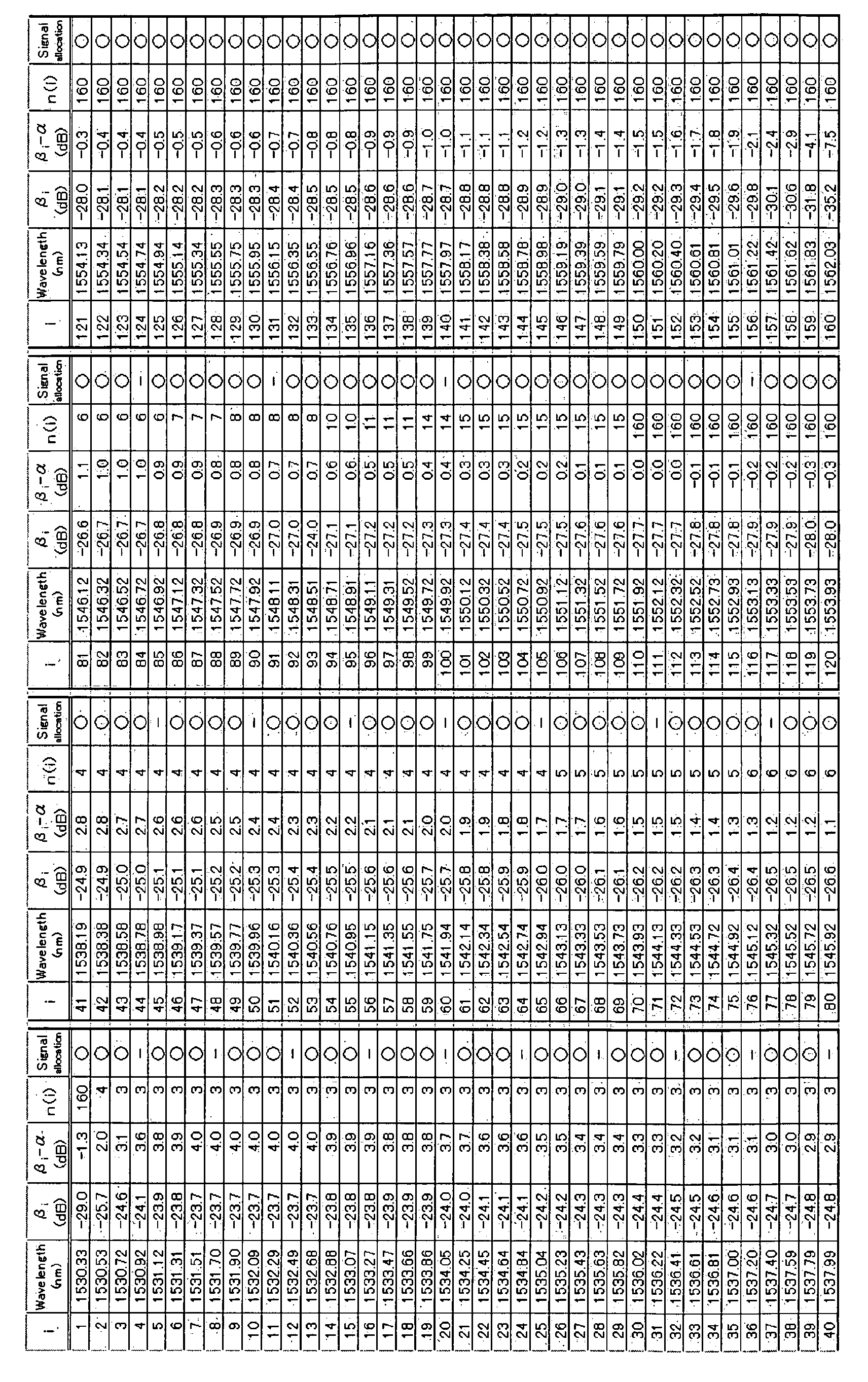
FIG. 3 is a diagram showing an example where the four-wave mixing
crosstalk amount β
i, determined for each wavelength number i, is plotted to
wavelength λ. Furthermore, Table 1 below lists specific numerical values for the
four-wave mixing crosstalk amount β
i in FIG. 3, and other parameters to be
described below, These numerical values are the calculation results of the four-wave
mixing crosstalk amounts β
i, for when, in a WDM optical transmission system
which uses a non-zero dispersion shifted fiber (NZ-DSF) of 100km as the optical
transmission path, and signal lights of 160 waves are allocated at equal wavelength
spacing of 25GHz, the input optical power to the optical transmission path is made
0dBm/ch, and the signal light polarization states are all coincident with each other.
in the numerical values of the calculation results shown in FIG. 3 and Table 1,
the four-wave mixing crosstalk amount (i for when the signal lights of 160 waves are
all allocated at equal spacing is in a range of between -36dB and -23dB, and as a
whole, the four-wave mixing crosstalk amount (i is larger on the short wavelength
side, with a difference of approximately 6dB from the long wavelength sides. The
reason why the four-wave mixing crosstalk amount is minimal at the wavelengths on
both ends is that wavelength combinations generating four-wave mixed light is less.
For the tolerance value ( (the single dot chain line in FIG. 3) determined in step 1 to
be -27.7 dB, the four-wave mixing crosstalk amount exceeding the tolerance value
( is generated between the wavelength number 2 and the wavelength number 109
(the range of wavelengths from 1530.53nm to 1551.72nm).
Next, in step 4, the four-wave mixing crosstalk amount for the case where the
signal lights of n waves (n = 2, 3, ...) are allocated consecutively on the equally
spaced wavelength grids, and the signal light is not allocated on one wavelength grid
adjacent to the grids on which a group of signal lights is allocated consecutively, that
is, for the case where the wavelength allocation corresponding to (n, 1) wavelength
groups is performed, is calculated for each wavelength number i (j = 2, ... 160), and
the results thereof are made ϒn_1. In other words, in step 4, the four-wave mixing
crosstalk amounts ϒn_1 to ϒn_160 for when the wavelength allocation is performed
corresponding to (n, 1) wavelength groups, are calculated.
The explanation is given by a specific example. Assuming that n = 3 and
performing the wavelength allocation corresponding to (3, 1) wavelength groups, the
wavelength allocation of the signal lights shown in the upper part of FIG. 4 is
obtained, and the four-wave mixing crosstalk amounts ϒ3_1 to ϒ3_160 as indicated by
the black dots in the lower part of FIG. 4 are calculated. Furthermore, assuming that
n = 5 and performing the wavelength allocation corresponding to (5, 1) wavelength
groups, the wavelength allocation of the signal lights shown in the upper part of FIG.
5 is obtained, and the four-wave mixing crosstalk amounts (5_1 to (5_160 as
indicated by the black dots in the lower part of FIG. 5 are calculated. The white dots
in both FIG. 4 and FIG. 5 are the four-wave mixing crosstalk amounts (i obtained in
step 3. Furthermore, also in the numerical calculations in FIG. 4 and FIG. 5, the
same conditions as for FIG. 3 are applied.
Next, in step 5, from those wavelength, groups in which the signal lights of n
waves are allocated consecutively in step 4, the wavelength group including the
center wavelength of, for example, the wavelength grids of 160 waves, is selected,
specifically, the wavelength group including the wavelength number i = 80 for when
the wavelength number is i = 1, 2,... in order from the short wavelength side. Here,
the wavelength group is selected based on the center wavelength of the wavelength
grids, but the wavelength group positioned at another location on the wavelength
grids may be selected instead. Furthermore, if there is no signal light on the
wavelength grid of i = 80, then the wavelength group including the signal light closest
to the wavelength grid of i = 80 is selected. Then, for the wavelength number im,
having the largest amount of four-wave mixing crosstalk, among the signal light in
that wavelength group, Cn defined by equation (7), in other words, a difference of
the four-wave mixing crosstalk amount (im obtained in step 4 from the four-wave
mixing crosstalk amount (im obtained in step 3, is obtained.
EMBED Equation.3 Cn-βim - γ n_im
Specifically, C
3 determined when n = 3 in FIC. 4, and C
5 determined when n
= 5 in FIG. 5, are shown in the respective figures. The numerical values shown in
Table 2 are a collection of specific examples of values of C
n with the value of n is
increased to 2, 3, and so on.
Next, in step 6, the wavelength number i where βi > α is determined, for the
wavelength numbers i (i = 1 to 160). Then, in step 7, for the wavelength number i
where βi > a, a value of n which satisfies a refationship in the equation (8) is
obtained, and the result thereof is made n(i). For the wavelength number i where βi
≤ α, a value of n(i) = 160 (the total number of wavelengths) is set.
Cn+1 <βi - α≤Cn
The processing in steps 6 and 7, when generalized, becomes the procedure
shown in a flowchart in FIG. 6. Specifically, in step 11 in FIG. 6, an initial value of
the wavelength number i is set to 1. in step 12, it is judged that the wavelength
number l is eqaul to or less than a maximum wavelength number k, and the
processing proceeds to step 13. If l > k, then the processing in steps 6 and 7 is
terminated, and the processing proceeds to step 8. In step 13, it is judged whether
or not the relationship βi > α is satisfied. If judged that βi > α, the processing
proceeds to step 14. On the other hand, if judged that βi < α, then in step 15, the
maximum wavelength number k is set to n(i) and the prooessing proceeds to step 19.
in step 15, 2 is set to an initial value of n. In step 16, it is judged whether or
not the relationship in equation (8) is satisfied. If judged that the relationship in
equation (8) is satisfied, then in step 17, the value of n at the time of judgment is set
to n(i), and the processing proceeds to step 19. On the other hand, if judged that the
relationship in equation (8) is not satisfied, then in step 18, the value of n is
incremented by one, and the processing returns to step 16. In step 19, the value of
the wavelength number i is incremented by one, the preceding returns to step 12,
and the above processing is repeated.
Examples of n(i) obtained for each wavelength number i in accordance with
the procedures of step 11 through step 19 are shown in Table 1 above. In the
specific examples of Table 1, wavelength numbers from 2 to 109 correspond to the
wavelength number i where βi> α, and n(i) value which satisfy equation (8) is in a
range from 3 to 15. Moreover, wavelength numbers 1 and 110 to 160 correspond to
the wavelength number i where βi ≤ (, and the wavelength number n(i) is 160.
Once the value of n(i) is obtained for each wavelength number i in step 7, the
processing proceeds to step 8, and it is determined whether or not to allocate the
signal lights on the wavelength grids corresponding to the wavelength numbers 1
through 160. Specifically, it is possible to determine the wavelength allocatian of
signal light in order from the smallest or from the largest for the wavelength number i.
Here, a detailed description is given of the procedure for determining the wavelength
allocation in order from the smallest for the wavelength number i,
First, as shown in Table 1, when the wavelength number is 1, the value of
n(1) is 160. Then, when the wavelength number is 2, the value of n(2) is 4.
Therefore, for the wavelength numbers 1 and 2, by allocating the signal lights of four
waves are allocated consecutively and not allocating the signal light on one
wavelength grid adjacent to the wavelength grids on which the group of signal lights
is allocated consecutively, that is, by performing the wavelength allocation
corresponding to (4, 1) wavelength groups, the four-wave mixing crosstalk amount
can be kept the tolerance value (or below. However, in the case where the signal
lights are allocated consecutively on the wavelength grids corresponding to the
wavelength numbers 1, 2, 3 and 4, since for the wavelength numbers 3 and 4, n(3)
and n(4) are both 3, the four-wave mixing crosstalk amount exceeds the tolerance
value (.
Therefore, consideration is given to the wavelength allocation according to (3,
1) wavelength groups, in which the signal lights of three waves are allocated
consecutively, and the signal light is not allocated on one wavelength grid adjacent
to the wavelengths grids on which the group of signal lights is allocated
consecutively. When the signal lights are allocated on the wavelength numbers 1, 2
and 3, the values of n(1) through n(3) are all 3 or above for any of these wavelength
numbers. Therefore, the four-wave mixing crosstalk amount can be kept the
tolerance value α or below. In other words, when N waves are allocated
consecutively, a value of N should be as large as possible, so that the value of n(i)
corresponding to each wavelength number is equal to or greater than N.
As described above, by selecting N = 3 for the wavelength group including
the signal light of the wavelength number 1, the wavelength allocation is determined
wherein the signal lights are allocated on the grids corresponding to the wavelength
numbers 1, 2 and 3, and the signal light is not allocated on the next wavelength grid
on the longer wavelength side from the longest wavelength grid of the wavelength
grids on which the signal lights are allocated consecutively, that is, the signal light is
not allocated on the wavelength grid corresponding to the wavelength number 4.
Next, the wavelength allocation of the signal light is determined for the
wavelength number 5 which is positioned on the next wavelength grid on the longer
wavelength side from the wavelength grid corresponding to the wavelength number
4 on which no signal light is allocated, in accordance with the same procedure as for
the wavelength number 1. In the examples in Table 1, since n(5) = 3, n(6) = 3 and
n(7) = 3; the wavelength allocation is determined wherein the signal lights are
allocated on the grids corresponding to the wavelength numbers 5, 6 and 7, but the
signal light is not allocated on the grid corresponding to the wavelength number 8.
These procedures are repeated for the subsequent wavelength numbers 9
through 160, determining in sequence whether or not to allocate the signal lights on
the grids corresponding to the respective wavelength numbers.
Generalizing the series of processes in step 8 results in the procedures
shown in a flowchart in FIG. 7. Specifically, in step 21 in FIG. 7, 1 is set as the initial
value of the wavelength number i. In step 22, it is judged that the wavelength
number i is equal to or less than the maximum wavelength number k (here 160), and
the processing proceeds to step 23. If i > k, then the series of processing in step 8 is
terminated. In step 23, it is judged whether or not the relationship βi > α is satisfied.
If judged that βi > α, the processing proceeds to step 24. On the other hand, if
judged that βi < α, then in step 25, the value of the wavelength number i is
incremented by one, and the processing returns to step 22.
In step 24, the wavelength number i which satisfies the relationship βi > α is
set as a minimum wavelength number j for use in the subsequent processing.
Furthermore, a variable m representing a value in a range from 1 to n(j) is set to 1.
In step 26, it is judged whether the minimum values of n(j), n(j + 1), ... n(j + n (j) -m)
are equal to or greater than n(j) - m + 1. If judged to be equal to or greater than n(j)
- m + 1, the processing proceeds to step 27, while if judged to be less than n(j) - m
+ 1, then in step 28, the value of the variable m is incremented by one and the
processing returns to step 26.
In step 27, it is judged whether the value of j + n(j) - m is less than the
maximum wavelength number k. If judged to be less than the maximum wavelength
number k, then in step 29, the signal lights are allocated on the wavelength grids
corresponding to the wavelength numbers from j to j + n(j) - m, but the signal light is
not allocated on the wavelength grid corresponding to the wavelength number + n(j)
- m + 1, and the processing proceeds to step 31. On the other hand, if judged to be
greater than the maximum wavelength number k, then in step 30, the the signal
lights are allocated on the wavelength grids corresponding to the wavelength
numbers through k, and the series of processing in step 8 is terminated.
in step 31, if j+n(j)-m+1 equals the maximum wavelength number k, then
the series of processing in step 8 is terminated, but if the value of j + n(j) - m + 1 has
not yet reached the maximum wavelength number k, then in step 32, after j + n(j) -
m + 2 is set to the wavelength number i, the processing returns to step 22.
When the processing from step 21 to step 32 is finished, as shown in the
schematic diagram of FIG. 1 and in the specific example in FIG. 8, finally, the
wavelength allocation is determined wherein the signal lights of 139 waves can be
allocated on the wavelength grids capable of allocating thereon the signal lights of
160 waves at equal spacing, while suppressing the four-wave mixing crosstalk
amount below the tolerance value (.
Next, the detailed description is given to the theory in that the four-wave
mixed light is reduced by such wavelength allocation of the signal light.
FIG. 9 is an example of wavelength dispersion characteristics of a NZ-DSF
used as the optical transmission path. As shown in FIG: 9, normally, a wavelength
dispersion value of an optical fiber has wavelength dependence. Therefore, since
the wavelength dependence is also present in a generation amount of four-wave
mixed light, it becomes effective to determine the wavelength allocation of the signal
light considering this wavelength dependence. In other words, since the generation
amount of four-wave mixed light is increased in the wavelength having a smaller
absolute wavelength dispersion value, it is necessary to minimize the number of
wavelengths to be allocated consecutively on the wavelength grids. Conversely,
since the generation amount of four-wave mixed light is decreased in the wavelength
having a larger absolute wavelength dispersion value, a large number of
wavelengths can be allocated consecutively. In this manner, by efficiently allocating
the signal lights on the wavelength grids based on the wavelength dependence'of
the generation amount of four-wave mixed light, it becomes possible to achieve the
suppression of the four-wave mixing crosstalk amount and the increase in
transmission capacity, compared to the conventional wavelength allocation method
in which the number of consecutively allocated wavelengths is uniform throughout
the signal wavelength band.
Here, a relationship between the wavelength allocation of signal light and the
generation amount of four-wave mixed light is described specifically, with reference
for example to the localized wavelength allocation diagram in FIG. 10. In the case
where, as shown in (A) of FIG. 10, all the signal lights are allocated at equal spacing,
the combinations of wavelength numbers which generate four-wave mixed light in
the wavelength corresponding to the
wavelength number 0 are those as shown in
Table 3 below,
| Four-wave mixed light degeneration | Combination |
| Degenerated four-wave mixed light | (-1,0,1) |
| (0,1.2) |
| (-2, -1, 0) |
| Non-degenerated four wave mixed light | (-3, -2, -1, 0) |
| (-2.-1,0.1) |
| (-1, 0,1, 2) |
| (0,1,2,3) |
However, here only the combinations of wavelength numbers including the minimum
wavelength spacing are shown. As shown in Table 3 above, for degenerated four-wave
mixed light, three combinations of wavelength numbers can be considered,
and for non-degenerated four-wave mixed light, four combinations of wavelength
numbers can be considered.
On the other hand, when as shown in (B) of FIG. 10, the signal light of three
waves are allocated consecutively but the signal light is not allocated on every fourth
grid, the combinations of wavelength numbers which generate four-wave mixed light
in the wavelength corresponding to the
wavelength number 0 are as shown in Table
4 below.
| Four-wave mixed light degeneration | Combination |
| Degenerated four-wave mixed light | (-1,0,1). |
| Non-degenerated four-wave mixed light | None |
As shown in Table 4, when the signal lights of three waves are allocated
consecutively, there is only one wavelength number combination, for degenerated
four-wave mixed light.
Furthermore, as shown in (C) in RG. 10, when the signal lights of four waves
are allocated consecutivefy but the signal light is not allocated on every fifth grids,
the combinations of wavelength numbers which generate four-wave mixed light in
the wavelength corresponding to the
wavelength number 0 are as shown in Table 5
below.
| Four-wave mixed light degeneration | Combination |
| Degenerated four-wave mixed light | (-1, 0, 1) |
| (-2, -1, 0) |
| Non-degenerated four-wave mixed light | (-2,-1,-0,1) |
As shown in Table 5, when the signal lights of four waves are allocated
consecutively, there are only two wavelength number combinations for degenerated
four-wave mixed fight, and one wavelength number combination for non-degenerated
four-wave mixed light.
Therefore, the number of wavelength combinations which generate four-wave
mixed light is decreased, the less the consecutively allocated signal lights are, and
the generation efficiency of four-wave mixed light is reduced. Accordingly, as with
the wavelength allocation of the signal light shown in FIG. 8, by minimizing the
number of consecutively allocated signal lights on the short wavelength side where
four-wave mixed light is generated easily, and allocating a greater number of signal
lights consecutively as the optical signal wavelength is increased, it becomes
possible to suppress the four-wave mixing crosstalk amount in each signal light
wavelength constant or below, and to secure the greatest possible transmission
capacity. Here, it is important that the number of consecutively allocated
wavelengths n satisfies the equation (6). The value of n need not necessarily be
incremented by one. For example, it is possible that after allocating the signal lights
of four waves consecutively, the signal lights of six waves are allocated
consecutively.
Specifically, in the example of the wavelength allocation in FIG. 8, the signal
lights of 139 waves are allocated on the wavelength grids capable of allocating
thereon the signal lights of 160 waves, and the wavelength numbers on which no
signal lights are allocated are 4, B, 12, 16, 20, 24, 28, 32, 38, 40, 45, 50, 55, 60, 65,
71, 77, 84, 91, 100 and 116, as indicated by the symbol - under "signal allocation" in
Table 1. The results of calculating the numerical value of four-wave mixing crosstalk
amount in this case, as shown at the bottom of FIG. 8, become below the tolerance
value α (-27.7dB) for all the wavelengths on which the signal lights of 139 waves are
allocated. As a result that the number of allocated signal lights is reduced from 160
waves to ,139 waves, although the transmission capacity is reduced by 13%, it
becomes possible to obtain an effect in that the maximum amount of four-wave
mixing crosstalk is reduced by about 4dB. This effect of reducing the four-wave
mixing crosstalk amount by 4dB is equivalent to an increase of approximately 2dB in
input optical power to the optical transmission path. Therefore, the transmission
distance can be made a maximum of approximately 1.6 times longer.
According to the wavelength allocation method of signal light according to the
present invention as described above, by optimizing according to wavelength bands,
the consecutive allocation wavelength number of signal lights to be allocated on the
wavelength grids, based on the wavelength dependence of the generation amount of
four-wave mixed light, it becomes possible to perform the wavelength allocation of
signal light efficiently, while suppressing the four-wave mixing crosstalk amount to a
constant value or below allowed by the system. By using such a wavelength
allocation method of signal light to determine the wavelength allocation of signal
lights transmitted between the optical transmission terminal apparatus 1 and the
optical reception terminal apparatus 3, for example in the typical WDM transmission
system as shown in FIG.12, it becomes possible to extend the transmission distance
while maintaining the large transmission capacity. Furthermore, in the WDM
transmission system mentioned above, it is possible to perform the wavelength
allocation of signal lights corresponding to standard wavelength grids such as ITU
grids, and basically since it is not necessary to keep the polarization state of signal
light constant, a low cost system can also be realized.
In the above wavelength allocation method of signal light, the specific
example has been shown in which the signal light is not allocated on one
wavelength grid adjacent to the wavelength grids on which the group of signal lights
are allocated consecutively. However, the wavelength allocation method of the
present invention can be applied effectively to the wavelength allocation of signal
light where it is necessary that the signal lights are not allocated on two or more
consecutive wavelength grids as shown in the top part of FIG. 13, for example, in
order to perform optical add/drop multiplexing, light level deviation compensation or
dispersion slope compensation, of signal lights of a plurality of wavelengths
collectively, in an OADM node or optical compensation node.
Specifically, in order to process the signal lights of 12 waves collectively in the
OADM node or optical compensation node as shown in FIG. 11, for example, then
for the wavelength allocation of signal light, applied with (12, 4) wavelength groups
where the consecutive wavelength grids for 12 waves and 4 waves are assigned,
and the signal lights are allocated on the wavelength grids for 12 waves and the
signal lights are not allocated on the wavelength grids for 4 waves, it is possible to
apply the present invention to determine the wavelength allocation of signal light to
the wavelength grids for 12 channel. Here, if the wavelength groups in which a
plurality of signal lights are collectively processed for optical add/drop multiplexing or
the like are called "upper level wavelength groups", then in an example in FIG. 11,
for the upper level wavelength groups G1 and G2 on the short wavelength side, (3,
1) wavelength groups are used wherein the signal light of three waves are allocated
consecutively, but the signal light is not allocated on one wavelength grid adjacent to
the wavelength grids on which the signal lights are allocated consecutively.
Furthermore, for the upper level wavelength group G3, (4, 1) wavelength groups are
used wherein the signal lights of four waves are allocated consecutively, and for the
upper level wavelength group G4, (6, 1) wavelength groups are used wherein the
signal lights of six waves are allocated.
By applying such wavelength allocations of signal light, it becomes possible to
perform the wavelength allocation of signal light efficiently while suppressing the
four-wave mixing crosstalk amount to the tolerance value α or below, even when
performing optical add/drop multiplexing, light level deviation compensation or
dispersion slope compensation of signal lights of the plurality of wavelengths
collectively, in the OADM node or optical compensation node.