EP1424533A2 - Structure connecting heat exchanger to shroud improving workability in assembling or disassembling them - Google Patents
Structure connecting heat exchanger to shroud improving workability in assembling or disassembling them Download PDFInfo
- Publication number
- EP1424533A2 EP1424533A2 EP03020561A EP03020561A EP1424533A2 EP 1424533 A2 EP1424533 A2 EP 1424533A2 EP 03020561 A EP03020561 A EP 03020561A EP 03020561 A EP03020561 A EP 03020561A EP 1424533 A2 EP1424533 A2 EP 1424533A2
- Authority
- EP
- European Patent Office
- Prior art keywords
- shroud
- heat exchanger
- brackets
- air
- projections
- Prior art date
- Legal status (The legal status is an assumption and is not a legal conclusion. Google has not performed a legal analysis and makes no representation as to the accuracy of the status listed.)
- Withdrawn
Links
- 238000010168 coupling process Methods 0.000 claims description 12
- 238000005859 coupling reaction Methods 0.000 claims description 12
- 238000003780 insertion Methods 0.000 claims description 2
- 230000037431 insertion Effects 0.000 claims description 2
- 238000001816 cooling Methods 0.000 abstract description 29
- 229910052751 metal Inorganic materials 0.000 description 8
- 239000002184 metal Substances 0.000 description 8
- 239000000945 filler Substances 0.000 description 6
- 230000003014 reinforcing effect Effects 0.000 description 6
- 238000005219 brazing Methods 0.000 description 5
- 239000000498 cooling water Substances 0.000 description 3
- 238000002844 melting Methods 0.000 description 3
- 230000008018 melting Effects 0.000 description 3
- 238000000034 method Methods 0.000 description 3
- 239000011347 resin Substances 0.000 description 3
- 229920005989 resin Polymers 0.000 description 3
- 239000004677 Nylon Substances 0.000 description 2
- 239000003365 glass fiber Substances 0.000 description 2
- 229920001778 nylon Polymers 0.000 description 2
- 239000003507 refrigerant Substances 0.000 description 2
- 229910000679 solder Inorganic materials 0.000 description 2
- 229910000838 Al alloy Inorganic materials 0.000 description 1
- 238000004378 air conditioning Methods 0.000 description 1
- 239000010953 base metal Substances 0.000 description 1
- 230000008878 coupling Effects 0.000 description 1
- 238000004512 die casting Methods 0.000 description 1
- 230000000694 effects Effects 0.000 description 1
- 230000005489 elastic deformation Effects 0.000 description 1
- 239000012530 fluid Substances 0.000 description 1
- -1 i.e. Substances 0.000 description 1
- 238000012986 modification Methods 0.000 description 1
- 230000004048 modification Effects 0.000 description 1
- 238000005476 soldering Methods 0.000 description 1
Images








Classifications
-
- F—MECHANICAL ENGINEERING; LIGHTING; HEATING; WEAPONS; BLASTING
- F28—HEAT EXCHANGE IN GENERAL
- F28F—DETAILS OF HEAT-EXCHANGE AND HEAT-TRANSFER APPARATUS, OF GENERAL APPLICATION
- F28F9/00—Casings; Header boxes; Auxiliary supports for elements; Auxiliary members within casings
- F28F9/001—Casings in the form of plate-like arrangements; Frames enclosing a heat exchange core
- F28F9/002—Casings in the form of plate-like arrangements; Frames enclosing a heat exchange core with fastening means for other structures
-
- F—MECHANICAL ENGINEERING; LIGHTING; HEATING; WEAPONS; BLASTING
- F28—HEAT EXCHANGE IN GENERAL
- F28D—HEAT-EXCHANGE APPARATUS, NOT PROVIDED FOR IN ANOTHER SUBCLASS, IN WHICH THE HEAT-EXCHANGE MEDIA DO NOT COME INTO DIRECT CONTACT
- F28D1/00—Heat-exchange apparatus having stationary conduit assemblies for one heat-exchange medium only, the media being in contact with different sides of the conduit wall, in which the other heat-exchange medium is a large body of fluid, e.g. domestic or motor car radiators
- F28D1/02—Heat-exchange apparatus having stationary conduit assemblies for one heat-exchange medium only, the media being in contact with different sides of the conduit wall, in which the other heat-exchange medium is a large body of fluid, e.g. domestic or motor car radiators with heat-exchange conduits immersed in the body of fluid
- F28D1/04—Heat-exchange apparatus having stationary conduit assemblies for one heat-exchange medium only, the media being in contact with different sides of the conduit wall, in which the other heat-exchange medium is a large body of fluid, e.g. domestic or motor car radiators with heat-exchange conduits immersed in the body of fluid with tubular conduits
- F28D1/0408—Multi-circuit heat exchangers, e.g. integrating different heat exchange sections in the same unit or heat exchangers for more than two fluids
- F28D1/0426—Multi-circuit heat exchangers, e.g. integrating different heat exchange sections in the same unit or heat exchangers for more than two fluids with units having particular arrangement relative to the large body of fluid, e.g. with interleaved units or with adjacent heat exchange units in common air flow or with units extending at an angle to each other or with units arranged around a central element
- F28D1/0435—Combination of units extending one behind the other
-
- F—MECHANICAL ENGINEERING; LIGHTING; HEATING; WEAPONS; BLASTING
- F01—MACHINES OR ENGINES IN GENERAL; ENGINE PLANTS IN GENERAL; STEAM ENGINES
- F01P—COOLING OF MACHINES OR ENGINES IN GENERAL; COOLING OF INTERNAL-COMBUSTION ENGINES
- F01P5/00—Pumping cooling-air or liquid coolants
- F01P5/02—Pumping cooling-air; Arrangements of cooling-air pumps, e.g. fans or blowers
- F01P2005/025—Pumping cooling-air; Arrangements of cooling-air pumps, e.g. fans or blowers using two or more air pumps
-
- F—MECHANICAL ENGINEERING; LIGHTING; HEATING; WEAPONS; BLASTING
- F01—MACHINES OR ENGINES IN GENERAL; ENGINE PLANTS IN GENERAL; STEAM ENGINES
- F01P—COOLING OF MACHINES OR ENGINES IN GENERAL; COOLING OF INTERNAL-COMBUSTION ENGINES
- F01P2070/00—Details
- F01P2070/50—Details mounting fans to heat-exchangers
-
- F—MECHANICAL ENGINEERING; LIGHTING; HEATING; WEAPONS; BLASTING
- F01—MACHINES OR ENGINES IN GENERAL; ENGINE PLANTS IN GENERAL; STEAM ENGINES
- F01P—COOLING OF MACHINES OR ENGINES IN GENERAL; COOLING OF INTERNAL-COMBUSTION ENGINES
- F01P2070/00—Details
- F01P2070/52—Details mounting heat-exchangers
-
- F—MECHANICAL ENGINEERING; LIGHTING; HEATING; WEAPONS; BLASTING
- F28—HEAT EXCHANGE IN GENERAL
- F28D—HEAT-EXCHANGE APPARATUS, NOT PROVIDED FOR IN ANOTHER SUBCLASS, IN WHICH THE HEAT-EXCHANGE MEDIA DO NOT COME INTO DIRECT CONTACT
- F28D21/00—Heat-exchange apparatus not covered by any of the groups F28D1/00 - F28D20/00
- F28D2021/0019—Other heat exchangers for particular applications; Heat exchange systems not otherwise provided for
- F28D2021/008—Other heat exchangers for particular applications; Heat exchange systems not otherwise provided for for vehicles
- F28D2021/0084—Condensers
-
- F—MECHANICAL ENGINEERING; LIGHTING; HEATING; WEAPONS; BLASTING
- F28—HEAT EXCHANGE IN GENERAL
- F28D—HEAT-EXCHANGE APPARATUS, NOT PROVIDED FOR IN ANOTHER SUBCLASS, IN WHICH THE HEAT-EXCHANGE MEDIA DO NOT COME INTO DIRECT CONTACT
- F28D21/00—Heat-exchange apparatus not covered by any of the groups F28D1/00 - F28D20/00
- F28D2021/0019—Other heat exchangers for particular applications; Heat exchange systems not otherwise provided for
- F28D2021/008—Other heat exchangers for particular applications; Heat exchange systems not otherwise provided for for vehicles
- F28D2021/0091—Radiators
- F28D2021/0094—Radiators for recooling the engine coolant
-
- F—MECHANICAL ENGINEERING; LIGHTING; HEATING; WEAPONS; BLASTING
- F28—HEAT EXCHANGE IN GENERAL
- F28F—DETAILS OF HEAT-EXCHANGE AND HEAT-TRANSFER APPARATUS, OF GENERAL APPLICATION
- F28F2275/00—Fastening; Joining
- F28F2275/08—Fastening; Joining by clamping or clipping
- F28F2275/085—Fastening; Joining by clamping or clipping with snap connection
Definitions
- the present invention relates to a structure connecting a shroud to a heat exchanger in order to fix an air blower to the heat exchanger, and is effective when applied to a vehicle.
- the present invention has been developed with the above-mentioned problems being taken into consideration, and the first object thereof is to provide a structure connecting a shroud to a heat exchanger, which is novel and different from the prior art.
- the second object is to improve the workability while assembling or disassembling a heat exchanger and a shroud.
- a structure for assembling a heat exchanger (1) and a shroud (4) comprises: an air blower (5) that sends a current of air to the heat exchanger (1); the shroud (4) that guides the current of air sent from the air blower (5) to the heat exchanger (1); and brackets (3) for mounting the heat exchanger (1) to a vehicle body; wherein the brackets (3) and the shroud (4) are pressed by part of the vehicle body and prevented from moving in the vertical direction in a state in which the horizontal movement of the shroud (4) with respect to the brackets (3) is prevented by projections (3b) that are formed on the top end sides of the brackets (3) and project upward, and the bottom end side of the shroud (4) is supported by support projections (3j) provided to the bracket (3).
- a structure connecting a shroud (4) to a heat exchanger (1) comprises: an air blower (5) that sends a current of air to the heat exchanger (1); and the shroud (4) that guides the current of air sent from the air blower (5) to the heat exchanger (1); wherein the heat exchanger (1) and the shroud (4) are pressed by part of a vehicle body and prevented from moving in the vertical direction in a state in which the horizontal movement of the shroud (4) with respect to the heat exchanger (1) is prevented by projections (3b) that are formed on the top end side of the heat exchanger (1) and project in a vertical direction, and the bottom end side of the shroud (4) is supported by support projections (3j) provided to the heat exchanger (1).
- a structure connecting a shroud (4) to a heat exchanger (1) comprises: an air blower (5) that sends a current of air to the heat exchanger (1); the shroud (4) that guides the current of air sent from the air blower (5) to the heat exchanger (1); and brackets (3) for mounting the heat exchanger (1) to a vehicle body; wherein the brackets (3) and the shroud (4) are prevented from moving in the vertical direction by tightening-coupling means (3h) provided at least to either of the brackets (3) or the shroud (4) in a state in which the horizontal movement of the shroud (4) with respect to the brackets (3) is prevented by projections (3b) that are formed on the top end sides of the brackets (3) and project upward, and the bottom end side of the shroud (4) is supported by support projections (3j) provided to the brackets (3).
- tightening-coupling means (3h) provided at least to either of the brackets (3) or the shroud (4) in a state in which the horizontal movement of the shroud
- a structure connecting a shroud (4) to comprises: an air blower (5) that sends a current of air to the heat exchanger (1); and the shroud (4) that guides the current of air sent from the air blower (5) to the heat exchanger (1); wherein the heat exchanger (1) and the shroud (4) are pressed by tightening-coupling means (3h) provided to the heat exchanger (1) and are prevented from moving in the vertical direction in a state in which the horizontal movement of the shroud (4) with respect to the heat-exchanger (1) is prevented by projections (3b) that are formed on the top end side of the heat exchanger (1) and project in a vertical direction, and the bottom end side of the shroud (4) is supported by support projections (3j) provided to the heat exchanger (1).
- tightening-coupling means (3h) provided to the heat exchanger (1) and are prevented from moving in the vertical direction in a state in which the horizontal movement of the shroud (4) with respect to the heat-exchanger (1) is prevented by projections (3b)
- the tightening-coupling means (3h) have at least an engaging-stopping projection that can displace elastically.
- the brackets (3) are provided with projections (3b) and the shroud (4) is provided with insertion holes (4a) into which the projections (3b) are inserted.
- plural heat exchangers (1, 2) are assembled to the brackets (3) so as to sandwich the brackets.
- the shroud (4) has a substantially L-shaped section which comprises: a top end portion that is assembled to projections of the brackets (3) (or the heat exchanger (1)); and an air guide portion that supports the air blower (5) and guides the current of air that has passed through the heat exchanger to the air blower (5).
- the structure connecting a shroud to a heat exchanger according to the present invention is applied to a structure for assembling a cooling module into which an on-board radiator and an outdoor heat exchanger, which is located outside an air-conditioned compartment, of an on-board air conditioning system have been integrated.
- FIG.1 is a perspective view of a cooling module viewed from the downstream side of a current of air
- FIG.2 is an enlarged view of part A shown in FIG. 1.
- a radiator 1 cools cooling water that circulates through an engine by exchanging heat between the cooling water and the air, and a condenser 2 (refer to FIG.1) cools and condenses a high-pressure refrigerant discharged from a compressor.
- the radiator 1 and the condenser 2 have a substantially identical structure, in concrete terms, comprising: a core section 1c comprising a plurality of tubes 1a, through which fluid, i.e., cooling water in the case of the radiator 1 and refrigerant in the case of the condenser 2, etc.
- header tanks 1d that are communicated with the plurality of tubes 1a at both ends in the direction of the length of the tubes 1a and that extend in the direction substantially perpendicular to the direction of the length of the tubes 1a; inserts 1e that are located at the ends of the core section 1c, extend in the direction parallel to the direction of the length of the tubes 1a, and reinforce the core section 1c; and so on, as shown in FIG.1; and in the present embodiment, all of these components are made of aluminum alloy and are integrated into one unit by brazing.
- the symbols of the tubes, fins, a core section, header tanks and inserts are only those relating to the radiator 1.
- Brazing is a technique to join two pieces of metal by using a brazing filler metal or solder without melting a base metal, according to, for example, "Bonding and Joining Technique", published by Tokyo Denki University Press.
- joining work which is done by using a filler metal whose melting point is above 450 °C is called brazing, and the filler metal is called a brazing filler metal, and when a filler metal whose melting point is below 450 °C is used for joining, it is called soldering and the filler metal is called a solder.
- the radiator 1 and the condenser 2 are arranged in such a way that core sections 1c thereof are parallel; i.e. one of the core surface of the radiator 1 is opposed to that of the condenser 2, and there is a fixed gap between the respective core sections 1c, and, at the same time, they are fixed to brackets 3 that are arranged so as to be sandwiched between the radiator 1 and the condenser 2 as shown in FIG.2, and they are attached to a vehicle body via the brackets 3.
- the bracket 3 comprises a bracket main body 3a, mounting pins 3b, mounting stays 3c, reinforcing parts 3d, and so on, as shown in FIG.3, and these components 3a to 3d are integrally formed into one unit by using a resin (for example, nylon containing glass fiber).
- a resin for example, nylon containing glass fiber
- the bracket main body 3a is a thin rectangular and extends in the vertical direction at the portions corresponding to the header tank 1d of the radiator 1 and the header tank of the condenser 2, that is, the positions corresponding to the ends of the radiator 1 and the condenser 2, and the mounting stays 3c are thin rectangular plate shape are provided at the top and bottom ends of the bracket main body 3a, and project toward the core sections of the radiator 1 and the condenser 2 from the bracket main body 3a.
- the mounting stays 3c are provided with the mounting pins 3b for assembling the cooling module, that is, the radiator 1 and the condenser 2 integrated into one unit by the brackets 3, to the vehicle body, and the mounting pins 3b are pin-shaped projections that project upward and downward from the mounting stays 3c.
- the reinforcing part 3d has a substantially triangular shape and is attached to the base side of the mounting stay 3c to support the moment produced at the junction of the mounting stay 3c and the bracket main body 3a, and a plurality of holes 3e are provided in the reinforcing part 3d in such a way that the hole penetrates through the reinforcing part 3d in the direction perpendicular to the core surface, that is, in the direction in which air should flow.
- the reinforcing part 3d has a truss structure and the strength thereof is prevented from being considerably reduced.
- the top end side of the radiator 1 is fixed to the brackets 3 by inserting snap fits 3f provided to the brackets 3 into holes 1f provided in the insert 1e, and the bottom end side thereof is fixed to the brackets 3 by inserting projections 3g formed on the bottom end sides of the brackets 3 into a recess, which is formed by making the section of the insert 1e into a substantially reversed-C shape, as shown in FIG.6.
- the snap fit 3f is a tightening-coupling means for detachably tightening, coupling, and fixing two members by utilizing the elastic deformation of projections formed into a hook-shape and, in the present embodiment, the snap fits 3f are integrally formed with the bracket 3.
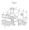
- the top end side of the condenser 2 is fixed to the brackets 3 by inserting parts of the brackets 3 into the insert 2e, as shown in FIG.4, and the bottom end side thereof is fixed to the brackets 3 by inserting the projections 3g into the recess of the insert 2e, as similar to the radiator 1 (refer to FIG.6).
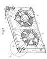
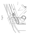
- a fan shroud 4 is prevented from moving with respect to the brackets 3 in the horizontal direction by inserting the mounting pins 3b into holes 4a (refer to FIG.9 and FIG.10) formed in the fan shroud 4, as shown in FIG.7 and FIG.8 and, at the same time, it is pressed by an upper member or a radiator support 6 which is a part of the vehicle body, as shown in FIG.11, and the movement of the fan shroud 4 in the vertical direction is prevented.
- the brackets 3 are provided with snap fits 3h that engage with the fan shroud 4 and fix the brackets 3 and the fan shroud 4 and, in addition to the case where the cooling module has been assembled to a vehicle, the fan shroud 4 is prevented from shifting from the proper position with respect to the brackets 3 in the case where the cooling module is not yet assembled to a vehicle, for example, while it is being transported.
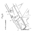
- the top end side of the fan shroud 4 is supported by support projections 3j provided to the brackets 3, as shown in FIG.9 and FIG.10.
- the support projection 3j has an umbrella-shaped flange at the front end side and the fan shroud 4 is prevented from moving downward and in the horizontal direction by inserting the support projections 3j into recess-shaped slots 4b (refer to FIG.9) provided in the fan shroud 4.
- the object of the fan shroud 4 is to support an air blower 5 (refer to FIG.9) that sends a current of cooling air to a heat exchanger such as the radiator 1 and, in the present embodiment, it has, in addition to the function as a support member, a function to prevent a current of air produced by the air blower 5 from flowing so as to skirt the air blower 5 and the radiator 1 by covering the gap between the air blower 5 and the radiator 1.
- the fan shroud 4 is assembled to the cooling module from above in such a way that the mounting pins 3b are inserted into the holes 4a (refer to FIG.9 and FIG.10), and, then, the cooling module, to which the fan shroud 4 has been assembled, is assembled to a vehicle (FIG.11).
- the bottom end side of the cooling module is fixed by inserting the mounting pins 3b into mounting holes of the vehicle body, and the top end side thereof is fixed in such a way that the top end side is pressed from above by brackets 6a of the vehicle body (FIG.11).
- the fan shroud 4 is assembled to the cooling module in such a way that the fan shroud 4 covers the brackets 3 that have been assembled to the cooling module, that is, the radiator 1 and the condenser 2 and, at the same time, the snap fits 3h and the vehicle body prevent the fan shroud 4 from being detached from the brackets 3.
- the mounting pins 3b and the snap fits 3h are provided to the header tank 1d of the radiator 1 at the upper side thereof and the support projections 3j are provided to the header tank 1d of the radiator 1 at the lower side thereof, as shown in FIG.12.
- the header tank 1d is made of resin (for example, nylon containing glass fiber), and the mounting pins 3b, the snap fits 3h, and the support projections 3j are integrally formed to the header tanks 1d.
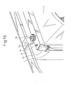
- the fan shroud 4 When assembled to the radiator 1, the fan shroud 4 is assembled to the cooling module from above in such a way that the mounting pins 3b are inserted into the holes 4a (refer to FIG.13 and FIG.14), similar to the first embodiment and, then, the cooling module, to which the fan shroud 4 has been assembled, is assembled to a vehicle body (FIG.15).
- the bracket main body 3a, the mounting pins 3b, the mounting stays 3c and the reinforcing sections 3d are integrally formed by resin, but the present invention is not limited to this and, for example, they may be made of metal by a press or by die-casting.
- the movement of the fan shroud 4 in the vertical direction is prevented by the snap fits 3h and the vehicle body, but the present invention is not limited to this, and the movement of the fan shroud 4 in the vertical direction may be prevented by either the snap fits 3h or the vehicle body.
- the present invention is applied to a heat exchanger module, into which different kinds of heat exchangers have been integrated by brackets, it is needless to say that the present invention can also be applied to a structure for connecting, for example, only the radiator 1 to the fan shroud 4.
- the structure is for connecting only the radiator 1 to the fan shroud 4, but it is needless to say that the structure can also be applied to, for example, a heat exchanger module, into which different kinds of heat exchangers have been integrated by brackets.
- the snap fits 3h are used as tightening-coupling means for preventing the movement in the vertical direction in the embodiments described above but the present invention is not limited to this and, for example, bolts may be used instead.
Landscapes
- Engineering & Computer Science (AREA)
- Physics & Mathematics (AREA)
- Thermal Sciences (AREA)
- Mechanical Engineering (AREA)
- General Engineering & Computer Science (AREA)
- Cooling, Air Intake And Gas Exhaust, And Fuel Tank Arrangements In Propulsion Units (AREA)
- Details Of Heat-Exchange And Heat-Transfer (AREA)
- Air-Conditioning For Vehicles (AREA)
Abstract
Description
Claims (8)
- A structure connecting a shroud (4) to a heat exchanger (1) comprising:wherein the brackets (3) and the shroud (4) are pressed by part of the vehicle body and prevented from moving in the vertical direction in a state in which the horizontal movement of the shroud (4) with respect to the brackets (3) is prevented by projections (3b) that are formed on the top end sides of the brackets (3) and project upward, and the bottom end side of the shroud (4) is supported by support projections (3j) provided to the brackets (3).an air blower (5) that sends a current of air to the heat exchanger (1);the shroud (4) that guides the current of air sent from the air blower (5) to the heat exchanger (1); andbrackets (3) for mounting the heat exchanger (1) to a vehicle body;
- A structure connecting a shroud (4) to a heat exchanger (1) comprising:wherein the heat exchanger (1) and the shroud (4) are pressed by part of a vehicle body and prevented from moving in the vertical direction in a state in which the horizontal movement of the shroud (4) with respect to the heat exchanger (1) is prevented by projections (3b) that are formed on the top end side of the heat exchanger (1) and projects in a vertical direction, and the bottom end side of the shroud (4) is supported by support projections (3j) provided to the heat exchanger (1).an air blower (5) that sends a current of air to the heat exchanger (1); andthe shroud (4) that guides the current of air sent from the air blower (5) to the heat exchanger (1);
- A structure connecting a shroud (4) to a heat exchanger (1) comprising:wherein the brackets (3) and the shroud (4) are prevented from moving in the vertical direction by tightening-coupling means (3h) provided at least to either of the brackets (3) or the shroud (4) in a state in which the horizontal movement of the shroud (4) with respect to the brackets (3) is prevented by projections (3b) that are formed on the top end sides of the brackets (3) and project upward, and the bottom end side of the shroud (4) is supported by support projections (3j) provided to the brackets (3).an air blower (5) that sends a current of air to the heat exchanger (1);the shroud (4) that guides the current of air sent from the air blower (5) to the heat exchanger (1); andbrackets (3) for mounting the heat exchanger (1) to a vehicle body;
- A structure connecting a shroud (4) to a heat exchanger (1) comprising:wherein the heat exchanger (1) and the shroud (4) are pressed by tightening-coupling means (3h) provided to the heat exchanger (1) and prevented from moving in the vertical direction in a state in which the horizontal movement of the shroud (4) with respect to the heat exchanger (1) is prevented by projections (3b) that are formed on the top end side of the heat exchanger (1) and project in a vertical direction, and the bottom end side of the shroud (4) is supported by support projections (3j) provided to the heat exchanger (1).an air blower (5) that sends a current of air to the heat exchanger (1); andthe shroud (4) that guides the current of air sent from the air blower (5) to the heat exchanger (1);
- A structure connecting a shroud to a heat exchanger, as set forth in claim 3 or 4, wherein the tightening-coupling means (3h) have engaging-stopping projections that can displace elastically.
- A structure connecting a shroud to a heat exchanger, as set forth in claim 1 or 3, wherein the brackets (3) are provided with the projections (3b) and the shroud (4) is provided with insertion holes (4a) into which the projections (3b) are inserted.
- A structure connecting a shroud to a heat exchanger, as set forth in claim 1 or 3, wherein plural heat exchangers are assembled to the brackets so as to sandwich the brackets.
- A structure connecting a shroud to a heat exchanger, as set forth in any one of claims 1 to 4, wherein the shroud has a substantially L-shaped section which comprises:a top end portion that is assembled to the projections of the brackets (or the heat exchanger); andan air guide portion that supports the air blower and guides the current of air that has passed through the heat exchanger to the air blower.
Applications Claiming Priority (2)
| Application Number | Priority Date | Filing Date | Title |
|---|---|---|---|
| JP2002272715A JP4062028B2 (en) | 2002-09-19 | 2002-09-19 | Assembly structure of heat exchanger and shroud |
| JP2002272715 | 2002-09-19 |
Publications (2)
| Publication Number | Publication Date |
|---|---|
| EP1424533A2 true EP1424533A2 (en) | 2004-06-02 |
| EP1424533A3 EP1424533A3 (en) | 2005-09-14 |
Family
ID=32063491
Family Applications (1)
| Application Number | Title | Priority Date | Filing Date |
|---|---|---|---|
| EP03020561A Withdrawn EP1424533A3 (en) | 2002-09-19 | 2003-09-17 | structure connecting a heat exchanger to a shroud |
Country Status (3)
| Country | Link |
|---|---|
| US (1) | US7044203B2 (en) |
| EP (1) | EP1424533A3 (en) |
| JP (1) | JP4062028B2 (en) |
Cited By (3)
| Publication number | Priority date | Publication date | Assignee | Title |
|---|---|---|---|---|
| EP1403606A2 (en) * | 2002-09-27 | 2004-03-31 | Denso Corporation | Heat exchanger module |
| WO2005038379A1 (en) * | 2003-10-17 | 2005-04-28 | Behr Gmbh & Co. Kg | Arrangement used to secure a fan frame |
| EP1686341A1 (en) * | 2005-01-28 | 2006-08-02 | DENSO THERMAL SYSTEMS S.p.A. | Cooling assembly for vehicles |
Families Citing this family (43)
| Publication number | Priority date | Publication date | Assignee | Title |
|---|---|---|---|---|
| DE10207025A1 (en) * | 2002-02-20 | 2003-08-28 | Behr Gmbh & Co | Mounting for vehicle radiator comprises clip at top and pivot at bottom |
| US20050230089A1 (en) * | 2004-04-05 | 2005-10-20 | Denso Corporation | Heat exchanger capable of preventing heat stress |
| US7775265B2 (en) * | 2004-09-15 | 2010-08-17 | Flex-A-Lite Consolidated, Inc. | Side tank design |
| JP4584041B2 (en) * | 2005-06-10 | 2010-11-17 | 本田技研工業株式会社 | Vehicle heat dissipation device |
| DE102005039090A1 (en) * | 2005-08-06 | 2007-02-08 | Behr Gmbh & Co. Kg | Assembly support system |
| US8011420B2 (en) * | 2006-03-13 | 2011-09-06 | Denso International America, Inc. | Condenser attachment bracket |
| US20080047504A1 (en) * | 2006-08-02 | 2008-02-28 | Guido Benvenuto | Fan shroud ring and method for its manufacture |
| US7703730B2 (en) * | 2006-10-20 | 2010-04-27 | Denso International America, Inc. | Fastenerless attachment system applied to vehicle engine cooling module components |
| WO2008115461A2 (en) | 2007-03-16 | 2008-09-25 | Polaris Industries Inc. | Vehicle |
| US8182217B2 (en) * | 2007-03-30 | 2012-05-22 | Denso International America, Inc. | Mechanical fan sub-shroud attachment feature, molded plastic snap feature |
| FR2922823B1 (en) * | 2007-10-25 | 2009-12-18 | Renault Sas | ARRANGEMENT FOR THE MOUNTING OF A HEAT EXCHANGER ON A VERTICAL STRUCTURE ELEMENT FORMING A TECHNICAL FRONT OF A MOTOR VEHICLE. |
| US20090194352A1 (en) * | 2008-01-31 | 2009-08-06 | Sean Plante | Movable Side-By-Side Cooling Package |
| US20090288897A1 (en) * | 2008-05-21 | 2009-11-26 | Adam Louramore | Radiator Bracket With Integrated Hood Pin Receptacle |
| FR2933487B1 (en) * | 2008-07-04 | 2010-11-05 | Tecumseh Europe Sa | DEVICE FOR ASSEMBLING A FAN FOR A REFRIGERATION UNIT |
| US20110100342A1 (en) * | 2009-11-02 | 2011-05-05 | International Engine Intellectual Property Company Llc | Forced convection egr cooling system |
| US8376073B2 (en) * | 2010-02-26 | 2013-02-19 | Nissan North America, Inc. | Vehicle radiator structure |
| US9618281B2 (en) | 2010-04-22 | 2017-04-11 | Denso International America, Inc. | Heat exchange device |
| JP5660024B2 (en) * | 2011-12-27 | 2015-01-28 | 株式会社デンソー | Heat exchanger assembly structure |
| KR101435665B1 (en) * | 2012-03-05 | 2014-09-23 | 한라비스테온공조 주식회사 | Cooling module |
| EP2672214A1 (en) | 2012-06-04 | 2013-12-11 | Alfa Laval Corporate AB | End-piece & plate heat exchanger comprising, and method of making, such end-piece |
| JP5954116B2 (en) * | 2012-10-29 | 2016-07-20 | 株式会社デンソー | bracket |
| CN106461352B (en) | 2014-05-08 | 2019-04-12 | 达纳加拿大公司 | Heat exchanger with the bracket that is slidably installed |
| EP2966393B1 (en) * | 2014-07-07 | 2020-10-21 | Valeo Autosystemy SP. Z.O.O. | An integrated bracket for automotive heat exchanger |
| JP6415890B2 (en) | 2014-08-04 | 2018-10-31 | 株式会社クボタ | Work vehicle |
| MX2017014403A (en) | 2015-05-15 | 2018-04-11 | Polaris Inc | UTILITY VEHICLE. |
| FR3047553B1 (en) | 2016-02-05 | 2019-05-17 | Valeo Systemes Thermiques | ASSEMBLY DEVICE BETWEEN A HEAT EXCHANGER OF AN AIR CONDITIONING INSTALLATION AND A COOLING RADIATOR OF THE ENGINE OF A MOTOR VEHICLE. |
| US11173808B2 (en) | 2016-12-22 | 2021-11-16 | Polaris Industies Inc. | Vehicle |
| WO2019017188A1 (en) | 2017-07-18 | 2019-01-24 | 株式会社クボタ | CONSTRUCTION MACHINE |
| JP6808587B2 (en) * | 2017-07-18 | 2021-01-06 | 株式会社クボタ | Work machine |
| DE102018200475A1 (en) * | 2018-01-12 | 2019-07-18 | Ford Global Technologies, Llc | Motor vehicle with radiator cover |
| JP6992542B2 (en) | 2018-01-24 | 2022-02-03 | トヨタ自動車株式会社 | Cooling module support structure |
| JP7331335B2 (en) * | 2018-07-24 | 2023-08-23 | 株式会社デンソー | assembly |
| CA3299413A1 (en) | 2019-04-30 | 2026-03-02 | Polaris Industries Inc. | Vehicle with removable final drive |
| US11691674B2 (en) | 2020-05-15 | 2023-07-04 | Polaris Industries Inc. | Off-road vehicle |
| US12187127B2 (en) | 2020-05-15 | 2025-01-07 | Polaris Industries Inc. | Off-road vehicle |
| CN116529549A (en) * | 2020-12-03 | 2023-08-01 | 摩丁制造公司 | Heat exchanger module |
| FR3123116B1 (en) * | 2021-05-20 | 2023-04-14 | Valeo Systemes Thermiques | Heat exchange system. |
| US11951797B2 (en) * | 2021-06-03 | 2024-04-09 | Brose Fahrzeugteile SE & Co. Kommanditgesellschaft, Würzburg | Cooling pack assembly |
| US12098733B2 (en) * | 2022-06-08 | 2024-09-24 | Modine Manufacturing Company | Fan shroud, mounting bracket, and pin mount |
| MX2023006716A (en) | 2022-06-13 | 2023-12-14 | Polaris Inc | POWER TRAIN FOR UTILITY VEHICLE. |
| AT526250B1 (en) * | 2023-01-30 | 2024-01-15 | Thomas Euler Rolle | Heat exchanger |
| JP7468736B1 (en) | 2023-03-23 | 2024-04-16 | いすゞ自動車株式会社 | Electric fan device and vehicle |
| EP4692522A1 (en) * | 2024-08-06 | 2026-02-11 | Modine Manufacturing Company | Fan shroud, mounting bracket, and pin mount |
Family Cites Families (27)
| Publication number | Priority date | Publication date | Assignee | Title |
|---|---|---|---|---|
| US3980132A (en) * | 1975-10-16 | 1976-09-14 | Caterpillar Tractor Co. | Heat exchanger with self-adjusting snap-on fan shroud |
| JPS60119321A (en) * | 1983-11-30 | 1985-06-26 | Nippon Denso Co Ltd | Regenerator with fan shroud |
| JPH032675Y2 (en) * | 1985-03-19 | 1991-01-24 | ||
| JPH02122120U (en) * | 1989-03-20 | 1990-10-05 | ||
| JP2502843Y2 (en) * | 1989-06-27 | 1996-06-26 | カルソニック株式会社 | Fan shroud mounting structure |
| JP2678666B2 (en) * | 1989-07-25 | 1997-11-17 | 本田技研工業株式会社 | Radiator |
| JP3191385B2 (en) * | 1991-07-12 | 2001-07-23 | 株式会社デンソー | Condenser mounting device |
| US5219016A (en) * | 1992-06-15 | 1993-06-15 | General Motors Corporation | Radiator, condenser and fan shroud assembly |
| DE4244037C2 (en) | 1992-12-24 | 1995-10-05 | Behr Gmbh & Co | Cooling unit for an internal combustion engine |
| DE9319025U1 (en) | 1993-12-11 | 1994-02-03 | Behr Gmbh & Co, 70469 Stuttgart | Heat exchanger with fan cover |
| JP3509920B2 (en) * | 1994-03-15 | 2004-03-22 | 株式会社デンソー | Engine cooling fan cowling mounting structure |
| JP3473095B2 (en) * | 1994-04-21 | 2003-12-02 | マツダ株式会社 | Radiator device for engine |
| DE4425350A1 (en) * | 1994-07-18 | 1996-01-25 | Behr Gmbh & Co | Arrangement for connecting two or more heat exchangers |
| GB9609440D0 (en) * | 1996-05-04 | 1996-07-10 | Ford Motor Co | Radiator and condenser assembly |
| JP4072701B2 (en) * | 1997-03-24 | 2008-04-09 | 株式会社ティラド | Heat exchanger shroud mounting structure |
| JP3799782B2 (en) | 1997-11-11 | 2006-07-19 | 株式会社デンソー | Vehicle heat exchanger device |
| JP3120281B2 (en) * | 1998-03-30 | 2000-12-25 | 東洋ラジエーター株式会社 | Shroud mounting structure for automotive heat exchanger |
| US6237676B1 (en) * | 1998-04-28 | 2001-05-29 | Denso Corporation | Heat exchanger for vehicle air conditioner |
| FR2785379B1 (en) * | 1998-10-29 | 2001-06-15 | Valeo Thermique Moteur Sa | HEAT EXCHANGE MODULE COMPRISING A FAN NOZZLE AND A HEAT EXCHANGER, PARTICULARLY FOR A MOTOR VEHICLE |
| JP3061037U (en) * | 1999-01-26 | 1999-09-14 | 東洋ラジエーター株式会社 | Assembly structure of composite heat exchanger for vehicles |
| US6273182B1 (en) * | 2000-05-19 | 2001-08-14 | Delphi Technologies, Inc. | Heat exchanger mounting |
| US6318450B1 (en) * | 2000-08-22 | 2001-11-20 | Delphi Technologies, Inc. | Fastener free automotive heat exchanger mounting |
| JP4201967B2 (en) * | 2000-09-25 | 2008-12-24 | カルソニックカンセイ株式会社 | Resin member mounting structure |
| JP4461609B2 (en) * | 2000-11-10 | 2010-05-12 | トヨタ自動車株式会社 | Electric fan shroud mounting structure |
| JP2002168588A (en) | 2000-11-30 | 2002-06-14 | Toyo Radiator Co Ltd | Composite heat exchanger for vehicle |
| JP3606203B2 (en) * | 2001-01-09 | 2005-01-05 | 日産自動車株式会社 | Motor fan unit mounting structure |
| US6510891B2 (en) * | 2001-04-27 | 2003-01-28 | Delphi Technologies, Inc. | Clip-retainer for heat exchanger |
-
2002
- 2002-09-19 JP JP2002272715A patent/JP4062028B2/en not_active Expired - Fee Related
-
2003
- 2003-09-17 US US10/666,056 patent/US7044203B2/en not_active Expired - Fee Related
- 2003-09-17 EP EP03020561A patent/EP1424533A3/en not_active Withdrawn
Cited By (5)
| Publication number | Priority date | Publication date | Assignee | Title |
|---|---|---|---|---|
| EP1403606A2 (en) * | 2002-09-27 | 2004-03-31 | Denso Corporation | Heat exchanger module |
| WO2005038379A1 (en) * | 2003-10-17 | 2005-04-28 | Behr Gmbh & Co. Kg | Arrangement used to secure a fan frame |
| EP1686341A1 (en) * | 2005-01-28 | 2006-08-02 | DENSO THERMAL SYSTEMS S.p.A. | Cooling assembly for vehicles |
| JP2006207588A (en) * | 2005-01-28 | 2006-08-10 | Denso Thermal Systems Spa | Cooling assembly for vehicle |
| US7325592B2 (en) | 2005-01-28 | 2008-02-05 | Denso Thermal Systems, S.P.A. | Cooling assembly for vehicles |
Also Published As
| Publication number | Publication date |
|---|---|
| US7044203B2 (en) | 2006-05-16 |
| JP4062028B2 (en) | 2008-03-19 |
| EP1424533A3 (en) | 2005-09-14 |
| JP2004108672A (en) | 2004-04-08 |
| US20040069442A1 (en) | 2004-04-15 |
Similar Documents
| Publication | Publication Date | Title |
|---|---|---|
| US7044203B2 (en) | Structure connecting heat exchanger to shroud improving workability in assembling or disassembling them | |
| US6827129B2 (en) | Vehicle-mounted structure for heat exchanger | |
| JP3043025B2 (en) | Heat exchanger | |
| JP2747379B2 (en) | Heat exchanger | |
| JP4779641B2 (en) | Combined heat exchanger | |
| JP4062033B2 (en) | Heat exchanger module | |
| US7131488B2 (en) | Heat exchanger module | |
| US20060237175A1 (en) | Heat exchanger for cehicle use | |
| US20070062671A1 (en) | Heat exchanger and production method for the heat exchanger | |
| US20030168270A1 (en) | Front end structure of vehicle with labyrinth structure forming means for cooling air to a radiator | |
| SE503085C2 (en) | Heat exchanger tank with end pieces, method of making such a tank, and heat exchanger provided with such | |
| US6607025B2 (en) | Heat-exchange module for a motor vehicle | |
| US6776223B2 (en) | Heat exchanger having bracket mounted on side plate of core unit | |
| JPH0930246A (en) | Vehicle heat exchange device | |
| JP4338877B2 (en) | Piping structure of heat exchanger | |
| KR20070038401A (en) | Tank structure of heat exchanger | |
| JP3106653B2 (en) | Installation equipment for condenser and air duct | |
| US6032727A (en) | Heat exchanger with an accessory, and a method of fastening the accessory on the heat exchanger | |
| JP4389793B2 (en) | Refrigerant radiator mounting structure | |
| JP2004132564A (en) | Heat exchanger module | |
| LU102213B1 (en) | Cooling module for an internal combustion engine | |
| JP4682765B2 (en) | Heat exchanger and heat exchanger manufacturing method | |
| JP4725269B2 (en) | Heat exchanger and heat exchanger manufacturing method | |
| JPH0961070A (en) | Heat exchanger | |
| KR100813345B1 (en) | Automotive Cooling Module |
Legal Events
| Date | Code | Title | Description |
|---|---|---|---|
| PUAI | Public reference made under article 153(3) epc to a published international application that has entered the european phase |
Free format text: ORIGINAL CODE: 0009012 |
|
| AK | Designated contracting states |
Kind code of ref document: A2 Designated state(s): AT BE BG CH CY CZ DE DK EE ES FI FR GB GR HU IE IT LI LU MC NL PT RO SE SI SK TR |
|
| AX | Request for extension of the european patent |
Extension state: AL LT LV MK |
|
| RTI1 | Title (correction) |
Free format text: STRUCTURE CONNECTING A HEAT EXCHANGER TO A SHROUD |
|
| PUAL | Search report despatched |
Free format text: ORIGINAL CODE: 0009013 |
|
| AK | Designated contracting states |
Kind code of ref document: A3 Designated state(s): AT BE BG CH CY CZ DE DK EE ES FI FR GB GR HU IE IT LI LU MC NL PT RO SE SI SK TR |
|
| AX | Request for extension of the european patent |
Extension state: AL LT LV MK |
|
| 17P | Request for examination filed |
Effective date: 20050930 |
|
| AKX | Designation fees paid |
Designated state(s): DE FR GB |
|
| 17Q | First examination report despatched |
Effective date: 20090326 |
|
| STAA | Information on the status of an ep patent application or granted ep patent |
Free format text: STATUS: THE APPLICATION IS DEEMED TO BE WITHDRAWN |
|
| 18D | Application deemed to be withdrawn |
Effective date: 20090807 |