EP1424528B1 - Wärmetauscher für ein Heizgerät - Google Patents
Wärmetauscher für ein Heizgerät Download PDFInfo
- Publication number
- EP1424528B1 EP1424528B1 EP20030017436 EP03017436A EP1424528B1 EP 1424528 B1 EP1424528 B1 EP 1424528B1 EP 20030017436 EP20030017436 EP 20030017436 EP 03017436 A EP03017436 A EP 03017436A EP 1424528 B1 EP1424528 B1 EP 1424528B1
- Authority
- EP
- European Patent Office
- Prior art keywords
- base body
- heat exchanger
- casing
- groove
- side end
- Prior art date
- Legal status (The legal status is an assumption and is not a legal conclusion. Google has not performed a legal analysis and makes no representation as to the accuracy of the status listed.)
- Expired - Lifetime
Links
- 239000007788 liquid Substances 0.000 claims 2
- 238000007789 sealing Methods 0.000 description 31
- 238000003825 pressing Methods 0.000 description 7
- 230000000694 effects Effects 0.000 description 6
- 239000007789 gas Substances 0.000 description 6
- 238000005304 joining Methods 0.000 description 3
- 238000004519 manufacturing process Methods 0.000 description 3
- 238000000034 method Methods 0.000 description 3
- 239000011324 bead Substances 0.000 description 2
- 239000008236 heating water Substances 0.000 description 2
- 239000000463 material Substances 0.000 description 2
- 229910000831 Steel Inorganic materials 0.000 description 1
- 238000005299 abrasion Methods 0.000 description 1
- 238000010521 absorption reaction Methods 0.000 description 1
- 230000002411 adverse Effects 0.000 description 1
- XAGFODPZIPBFFR-UHFFFAOYSA-N aluminium Chemical compound [Al] XAGFODPZIPBFFR-UHFFFAOYSA-N 0.000 description 1
- 229910052782 aluminium Inorganic materials 0.000 description 1
- 230000015572 biosynthetic process Effects 0.000 description 1
- 238000005266 casting Methods 0.000 description 1
- 238000005253 cladding Methods 0.000 description 1
- 238000002485 combustion reaction Methods 0.000 description 1
- 238000005260 corrosion Methods 0.000 description 1
- 230000007797 corrosion Effects 0.000 description 1
- 238000002788 crimping Methods 0.000 description 1
- 230000003247 decreasing effect Effects 0.000 description 1
- 230000005489 elastic deformation Effects 0.000 description 1
- 229920001971 elastomer Polymers 0.000 description 1
- 239000000806 elastomer Substances 0.000 description 1
- 239000002737 fuel gas Substances 0.000 description 1
- 238000010438 heat treatment Methods 0.000 description 1
- 230000002093 peripheral effect Effects 0.000 description 1
- 238000005096 rolling process Methods 0.000 description 1
- 238000007528 sand casting Methods 0.000 description 1
- 239000007921 spray Substances 0.000 description 1
- 239000010959 steel Substances 0.000 description 1
- XLYOFNOQVPJJNP-UHFFFAOYSA-N water Substances O XLYOFNOQVPJJNP-UHFFFAOYSA-N 0.000 description 1
Images



Classifications
-
- F—MECHANICAL ENGINEERING; LIGHTING; HEATING; WEAPONS; BLASTING
- F24—HEATING; RANGES; VENTILATING
- F24H—FLUID HEATERS, e.g. WATER OR AIR HEATERS, HAVING HEAT-GENERATING MEANS, e.g. HEAT PUMPS, IN GENERAL
- F24H3/00—Air heaters
- F24H3/02—Air heaters with forced circulation
- F24H3/06—Air heaters with forced circulation the air being kept separate from the heating medium, e.g. using forced circulation of air over radiators
- F24H3/065—Air heaters with forced circulation the air being kept separate from the heating medium, e.g. using forced circulation of air over radiators using fluid fuel
-
- F—MECHANICAL ENGINEERING; LIGHTING; HEATING; WEAPONS; BLASTING
- F16—ENGINEERING ELEMENTS AND UNITS; GENERAL MEASURES FOR PRODUCING AND MAINTAINING EFFECTIVE FUNCTIONING OF MACHINES OR INSTALLATIONS; THERMAL INSULATION IN GENERAL
- F16J—PISTONS; CYLINDERS; SEALINGS
- F16J15/00—Sealings
- F16J15/02—Sealings between relatively-stationary surfaces
- F16J15/06—Sealings between relatively-stationary surfaces with solid packing compressed between sealing surfaces
- F16J15/062—Sealings between relatively-stationary surfaces with solid packing compressed between sealing surfaces characterised by the geometry of the seat
-
- F—MECHANICAL ENGINEERING; LIGHTING; HEATING; WEAPONS; BLASTING
- F24—HEATING; RANGES; VENTILATING
- F24H—FLUID HEATERS, e.g. WATER OR AIR HEATERS, HAVING HEAT-GENERATING MEANS, e.g. HEAT PUMPS, IN GENERAL
- F24H1/00—Water heaters, e.g. boilers, continuous-flow heaters or water-storage heaters
- F24H1/22—Water heaters other than continuous-flow or water-storage heaters, e.g. water heaters for central heating
- F24H1/24—Water heaters other than continuous-flow or water-storage heaters, e.g. water heaters for central heating with water mantle surrounding the combustion chamber or chambers
- F24H1/26—Water heaters other than continuous-flow or water-storage heaters, e.g. water heaters for central heating with water mantle surrounding the combustion chamber or chambers the water mantle forming an integral body
- F24H1/263—Water heaters other than continuous-flow or water-storage heaters, e.g. water heaters for central heating with water mantle surrounding the combustion chamber or chambers the water mantle forming an integral body with a dry-wall combustion chamber
Definitions
- the invention relates to a heat exchanger for a heater according to the preamble of claim 1.
- a heat exchanger is from document US-A-4,169,431 already known.
- a heat exchanger of this kind is from the FR 695 311 known.
- a cylindrical base body which is produced by casting, executed inside with a hot gas and on the outer wall with a spiral water channel for heating water to be heated.
- the water channel is formed by a spiral formed into the lateral surface of the outer wall trench, which is surrounded to the outside with a circumference surrounding the outer wall separate enclosure, so that the closed spiral water channel results on the outer surface of the body.
- At the upper and lower end portion of the main body is connected to the enclosure by means of a fastening means not specified.
- a seal between the body and the enclosure at least at the upper and lower end portion is necessary.
- Such seals are usually made with elastomer seals, O-rings, quad rings or specially shaped lip seals, wherein the seals lie in a groove of the body and the pressure of the seal can be produced by pushing the sheath.
- a disadvantage of this type of sealing is the translational stress of the seal during the joining process, wherein the seal during a long distance of movement of the envelope is already engaged with increasing pressure. This can make the seal be damaged due to abrasion or pulled in whole or in part in the gap between the body and sheath and damaged at the edge. In such an embodiment of the seal between the base body and the envelope, a failure rate of the heat exchanger can not be ruled out due to a possible pre-damage of the seal.
- a heat exchanger which is composed of two parts, namely an inner shell and an outer shell, wherein between the inner shell and the outer shell, an annular space is formed for flow through the heat transfer medium.
- the two parts, inner shell and outer shell are each designed in an open side with a flange, which is encapsulated by means of a spray mass.
- Object of the present invention is to provide a heat exchanger with a base body and a cladding of the outer wall, which has a simple and secure seal between the body and enclosure and damage to the seal when mounting the enclosure is excluded.
- the heat exchanger according to the invention with the characterizing features of claim 1 has the advantage that a simple and secure seal between body and enclosure realized and damage to the seal during the joining process of body and enclosure is avoided. With the realization of the seal at the same time an axial locking of the envelope on the body is possible.
- an additional positive fixing of the envelope on the base body is realized.
- a secure axial locking of the envelope is additionally produced on the base body.
- the axial locking is particularly useful to realize when this positive fixing is done together with the deformation that causes the pressing force on the sealing element.
- the formation of a groove for additional locking surface is particularly suitable. But it is also possible to produce by an additional forming an additional positive fixation of the envelope on the body.
- a conical design of the body and the enclosure allow a simplification of the joining process of the body and enclosure.
- the grooves can be introduced radially into the lateral surface of the outer wall of the base body and / or axially in the end face of the base body at the burner-side end portion and the exhaust-side end portion.
- FIG. 1 shows a heat exchanger for a heater with a base body 10 having an inner wall 11 and an outer wall 12 and a burner-side end portion 13 and an exhaust-side end portion 14, wherein the burner-side end portion 13, a burner-side end face 15 and the exhaust-side end portion 14, an exhaust-side end face 16 are formed ,
- the burner-side end face 15 is an opening 17, in which a burner, not shown, is used.
- an exhaust port 18 is provided, via which the fuel gas generated by the burner is discharged as exhaust gas.
- the main body 10 is, for example, an aluminum sand casting component, which due to its corrosion resistance and heat absorption and thermal conductivity especially suitable as material for heaters that are operated in condensing operation.
- the base body 10 is designed with a circular cross-section and extends, for example, slightly conical with decreasing diameter from the burner-side end face 15 to the exhaust-side end face 16. However, it is just as possible to carry out the basic body 10 cylindrically or with an oval cross-section.
- a hot gas 19 through which the hot gas generated by the burner flows.
- the inner wall 11 has various longitudinal ribs 21 and transverse ribs 22 to increase the heat exchanger surface.
- the outer wall 12 of the main body 10 spirally extends a trench-shaped recess 23 with a circumferential wall 24, wherein the recess 23 is open at the base 10 to the outside.
- the lateral surface of the outer wall 12 of the base body 10 is surrounded by a sheath 20, which is made for example of steel.
- the envelope 20 is a separate component, which closes the trench-shaped recess 23 to the outside, so that a spiral running, closed water channel 25 is formed for the heating water to be heated.
- the sheath 20 is pushed from the exhaust-side end portion 14 onto the base body 10 until the sheath 20 bears against the outer circumferential surface of the base body 10.
- a connecting piece 28 is disposed in the enclosure 20 at the burner-side end portion 13 of the body 10.
- An unillustrated further connection piece for the Edelwasserschreiblauf is introduced, for example, in the exhaust side end face 16 of the base body 10.
- a sealing element 30 is a sealing ring, for example an O-ring, or a specially shaped lip seal.
- the depth of the groove 26 is selected so that the inserted into the groove 26 sealing ring 30 is below the outer surface 12 formed by the outer wall 12 of the base body. This is achieved by by the depth of the groove 26 is selected to be greater than the diameter or the thickness of the sealing ring 30. This ensures that when the sheath 20 is pushed onto the base body 10, the sheath 20 does not slide on the sealing ring 30.
- the circumferential deformations 33 are expediently produced by rolling, wherein the depth of the deformations 33 must be designed such that the deformation 33 exerts a pressing force on the respective sealing ring 30.
- Characterized the sealing rings 30 are elastically deformed in the grooves 26, 27 and thereby generate the required sealing effect between the base body 10 and sheath 20, which is necessary to seal the water channel 25 to the outside.
- FIG. 3 out A second embodiment for forming a seal between the base body 10 and sheath 20 is made FIG. 3 out.
- the groove 26 is additionally introduced into a base 36 of a recess 37. It is important to ensure that the sealing ring 30 is beyond the plane of the base 36 also, so that in the production of the deformation 33 this can exert the same on the sealing ring 30 a pressing force for elastic deformation.
- the depth of the grooves 26, 27 may not be greater than the diameter of the sealing ring 30. To avoid sliding of the sheath 20 on the sealing ring 30 during assembly, however, this embodiment requires that the depth of the recess 37 is greater as the over the base surface 36 projecting portion of the sealing ring 30th
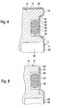
- FIG. 4 A third embodiment for realizing a seal between the base body 10 and the envelope 20 shows FIG. 4 ,
- the groove 26 is similar to the embodiment in FIG. 3 introduced into a recess 41 having a base 46.
- the depression 41 has, on the side facing away from the burner-side end face 13, a bevel 48 extending into the groove 26 with an inclination angle ⁇ of, for example, 65 °.
- the Bevel 48 acts as Umformkante and it arises while fixing the sheath 20 on the base body 10 in the axial direction.
- the casing 20 is additionally provided on the burner-side end face 15 with a bead 49, which realizes an additional axial fixation of the casing 20 on the base body 10.
- FIG. 5 a further embodiment of a seal on the burner-side end portion 13 of the base body 10 is shown.
- the radial groove 26 is radially introduced in a recessed from the outer surface of the base body 10 section 56.
- the recessed portion 56 runs out at the burner-side end face 15.
- the depth of the groove 26 is chosen so that the sealing ring 30 projects beyond the radial surface of the recessed portion 56.
- FIGS. 6 and 7 Two embodiments of a seal of the enclosure 20 on the base body 10 of the heat exchanger, in which the seal are realized on the axial end faces of the base body 10, go out of the FIGS. 6 and 7 out.
- the burner-side groove 26 is incorporated in the burner-side end face 15 and the exhaust-side groove 27 in the exhaust-side end face 16.
- the axial extent of the sheath 20 is chosen so that the sheath 20 with a burner-side portion 58 and an exhaust-side section 59 projects beyond the respective end face 15, 16.
- the material of the casing 20 is pressed onto the burner-side end face 15 or the exhaust-gas-side end face 16.
- a pressing force acts on the sealing ring 30, so that the necessary sealing effect between the base body 10 and the envelope 20 is formed.
- the grooves 26, 27 are incorporated in the edges between the outer wall 12 and the end faces 15, 16.
- the radial depth of the grooves 26, 27 is dimensioned so that the sealing ring 30 does not protrude beyond the lateral surface of the outer wall 12 in the idle state.
- the axial depth of the grooves 26, 27 is dimensioned such that a pressing force on the sealing rings 30 can act through the flanging of the burner-side section 58 and the exhaust-side section 59.
Landscapes
- Engineering & Computer Science (AREA)
- General Engineering & Computer Science (AREA)
- Physics & Mathematics (AREA)
- Mechanical Engineering (AREA)
- Thermal Sciences (AREA)
- Chemical & Material Sciences (AREA)
- Combustion & Propulsion (AREA)
- Geometry (AREA)
- Heat-Exchange Devices With Radiators And Conduit Assemblies (AREA)
Description
- Die Erfindung betrifft einen Wärmetauscher für ein Heizgerät nach dem Oberbegriff des Anspruchs 1. Ein solcher Wärmetauscher ist aus Dokument
US-A-4 169 431 schon bekannt. - Ein Wärmetauscher dieser Art ist aus der
FR 695 311 - Aufgrund der zweiteiligen Ausführung des Wärmetauschers ist eine Abdichtung zwischen dem Grundkörper und der Umhüllung zumindest am oberen und unteren Endabschnitt notwendig. Derartige Abdichtungen werden üblicherweise mit Elastomere-Dichtungen, O-Ringen, Quad-Ringen oder speziell geformten Lippendichtungen hergestellt, wobei die Dichtungen in einer Nut des Grundkörpers liegen und die Pressung der Dichtung durch das Aufschieben der Umhüllung herstellbar ist. Ein Nachteil dieser Art der Abdichtung ist die translatorische Beanspruchung der Dichtung während des Fügevorgangs, wobei die Dichtung während einer langen Bewegungsstrecke der Umhüllung bereits bei ansteigender Pressung im Eingriff ist. Dadurch kann die Dichtung aufgrund von Abrieb beschädigt werden oder ganz oder teilweise in den Spalt zwischen Grundkörper und Umhüllung hineingezogen und an der Kante beschädigt werden. Bei einer derartigen Ausführung der Dichtung zwischen Grundkörper und Umhüllung ist aufgrund einer möglichen Vorschädigung der Dichtung eine Ausfallrate des Wärmetauschers nicht auszuschließen.
- Aus der
US 4 169 431 A geht ein Wärmetauscher für ein Heizgerät hervor, bei dem auf einen Grundkörper eine Umhüllung aufgebracht ist, die zur Ausbildung eines Wassermantels des Wärmetauschers dient. Die äußere Umhüllung weist an den Enden und umlaufende Abschnitte auf, die auf jeweils einen Rand des Grundkörpers aufpressbar sind. Zusätzlich ist an diesen Stellen eine Dichtung eingebracht, um eine dichte Verbindung zwischen Grundkörper und Umhüllung zu realisieren. - Weiterhin beschreibt die
DE 34 00 048 A einen Wärmeübertrager, der aus zwei Teilen zusammengesetzt ist, und zwar aus einem Innenmantel und einem Außenmantel, wobei zwischen dem Innenmantel und dem Außenmantel ein Ringraum zur Durchströmung des Wärmeträgermediums ausgebildet ist. Die beiden Teile, Innenmantel und Außenmantel, sind in einer offenen Seite jeweils mit einem Flansch ausgeführt, der mittels einer Spritzmasse umspritzt ist. - Aufgabe der vorliegenden Erfindung ist es, eine Wärmetauscher mit einem Grundkörper und einer Umhüllung der Außenwand zu schaffen, der eine einfache und sichere Dichtung zwischen Grundkörper und Umhüllung aufweist sowie eine Beschädigung der Dichtung beim Aufziehen der Umhüllung ausgeschlossen wird.
- Der erfindungsgemäße Wärmetauscher mit den kennzeichnenden Merkmalen des Anspruchs 1 hat den Vorteil, dass eine einfache und sichere Dichtung zwischen Grundkörper und Umhüllung realisiert sowie eine Beschädigung der Dichtung während des Fügevorganges von Grundkörper und Umhüllung vermieden wird. Mit der Realisierung der Dichtung ist zugleich einen axiale Arretierung der Umhüllung am Grundkörper möglich.
- Zusätzlich zur Herstellung der Dichtwirkung wird eine zusätzliche formschlüssige Fixierung der Umhüllung am Grundkörper realisiert. Dadurch wird zusätzlich eine sichere axiale Arretierung der Umhüllung am Grundkörper erzeugt. Die axiale Arretierung ist besonders zweckmäßig zu realisieren, wenn diese formschlüssige Fixierung zusammen mit der Verformung erfolgt, die die Presskraft auf das Dichtelement bewirkt. Dabei ist die Ausbildung einer zur Nut zusätzlichen Arretierfläche besonders geeignet. Es ist aber auch möglich, durch einen zusätzlichen Umformvorgang eine zusätzliche formschlüssige Fixierung der Umhüllung am Grundkörper zu erzeugen. Eine konische Ausbildung des Grundkörpers und der Umhüllung ermöglichen eine Vereinfachung des Fügevorganges von Grundkörper und Umhüllung. Die Nuten können dabei am brennerseitigen Endabschnitt und am abgasseitigen Endabschnitt radial in die Mantelfläche der Außenwand des Grundkörpers und/oder axial in die Stirnfläche des Grundkörpers eingebracht sein.
- Ausführungsbeispiele der Erfindung sind in der Zeichnung dargestellt und in der nachfolgenden Beschreibung näher erläutert.
- Es zeigen:
- Figur 1
- eine Schnittdarstellung durch einen Wärmetauscher,
- Figur 2
- eine vergrößerte Schnittdarstellung einer Dichtung gemäß einem ersten Ausführungsbeispiel,
- Figur 3
- eine vergrößerte Schnittdarstellung einer Dichtung gemäß einem zweiten Ausführungsbeispiel,
- Figur 4
- eine vergrößerte Schnittdarstellung durch eine Dichtung gemäß einem dritten Ausführungsbeispiel,
- Figur 5
- eine vergrößerte Schnittdarstellung durch eine Dichtung gemäß einem vierten Ausführungsbeispiel,
- Figur 6
- eine vergrößerte Schnittdarstellung durch eine am brennerseitigen und abgasseitigen Endabschnitt des Grundkörpers ausbildete Dichtung gemäß einem fünften Ausführungsbeispiel und
- Figur 7
- eine vergrößerte Schnittdarstellung durch eine am brennerseitigen und abgasseitigen Endabschnitt des Grundkörpers ausgebildete Dichtung gemäß einem sechsten Ausführungsbeispiel.
-
Figur 1 zeigt einen Wärmetauscher für ein Heizgerät mit einem Grundkörper 10 mit einer Innenwand 11 und einer Außenwand 12 sowie mit einem brennerseitigen Endabschnitt 13 und einem abgasseitigen Endabschnitt 14, wobei am brennerseitigen Endabschnitt 13 eine brennerseitige Stirnfläche 15 und am abgasseitigen Endabschnitt 14 eine abgasseitige Stirnfläche 16 ausgebildet sind. In der brennerseitigen Stirnfläche 15 befindet sich eine Öffnung 17, in die ein nicht dargestellter Brenner eingesetzt wird. In der abgasseitigen Stirnfläche 16 ist eine Abgasöffnung 18 vorhanden, über die das vom Brenner erzeugte Heizgas als Abgas abgeleitet wird. - Der Grundkörper 10 ist beispielsweise ein Aluminium-Sandguss-Bauteil, das sich aufgrund seiner Korrosionsbeständigkeit sowie Wärmeaufnahme und Wärmeleitfähigkeit besonders als Material für Heizgeräte eignet, die im kondensierenden Betrieb betrieben werden. Der Grundkörper 10 ist mit einem kreisförmigen Querschnitt ausgeführt und verläuft beispielsweise von der brennerseitigen Stirnfläche 15 zur abgasseitigen Stirnfläche 16 hin mit abnehmendem Durchmesser leicht konisch. Es ist aber genauso möglich, den Grundkörper 10 zylindrisch oder mit einem ovalen Querschnitt auszuführen. Im Inneren des Grundkörpers 10 befindet sich ein Heizgaszug 19, durch den das vom Brenner erzeugten Heizgases strömt. Innerhalb des Heizgaszuges 19 weist die Innenwand 11 verschiedene Längsrippen 21 und Querrippen 22 zur Vergrößerung der Wärmetauscherfläche auf.
- An der Außenwand 12 des Grundkörpers 10 verläuft spiralförmig eine grabenförmig Vertiefung 23 mit einer umlaufenden Wand 24, wobei die Vertiefung 23 am Grundkörper 10 nach außen hin offen ist. Die Mantelfläche der Außenwand 12 des Grundkörpers 10 ist mit einer Umhüllung 20 umgeben, die beispielsweise aus Stahl ausgeführt ist. Die Umhüllung 20 ist ein separates Bauteil, das die grabenförmige Vertiefung 23 nach außen hin abschließt, so dass ein spiralförmig verlaufender, geschlossener Wasserkanal 25 für das zu erwärmende Heizwasser entsteht. Zur Herstellung des Wärmetauschers wird die Umhüllung 20 von dem abgasseitigen Endabschnitt 14 aus auf den Grundkörper 10 aufgeschoben bis die Umhüllung 20 an der äußeren Mantelfläche des Grundkörpers 10 anliegt.
- Zum Anschluss eines Heizwasservorlaufes ist in der Umhüllung 20 am brennerseitigen Endabschnitt 13 des Grundkörpers 10 ein Anschlussstutzen 28 angeordnet. Ein nicht dargestellter weiterer Anschlussstutzen für den Heizwasserrücklauf ist beispielsweise in die abgasseitige Stirnfläche 16 des Grundkörpers 10 eingebracht.
- Am brennerseitigen Endabschnitt 13 befindet sich im Grundkörper eine radial umlaufende, brennerseitige Nut 26 und am abgasseitigen Endabschnitt 14 eine radial umlaufende, abgasseitige Nut 27. In den Nuten 26, 27 befindet sich jeweils ein Dichtelement 30. Als Dichtelement 30 eignet sich ein Dichtring, beispielsweise ein O-Ring, oder eine speziell geformte Lippendichtung.
- Gemäß einem ersten Ausführungsbeispiel in
Figur 2 ist die Tiefe der Nut 26 so gewählt, dass der in die Nut 26 eingelegte Dichtring 30 unterhalb der von der Außenwand 12 des Grundkörpers 10 gebildeten äußeren Mantelfläche liegt. Dies wird dadurch erreicht, indem die Tiefe der Nut 26 größer als der Durchmesser bzw. die Stärke des Dichtrings 30 gewählt wird. Dadurch wird gewährleistet, dass beim Aufschieben der Umhüllung 20 auf den Grundkörper 10 die Umhüllung 20 nicht auf dem Dichtring 30 gleitet. - Zur Herstellung einer Dichtwirkung zwischen der Umhüllung 20 und dem Grundkörper 10 am brennraumseitigen Endabschnitt 13 und am abgasseitigen Endabschnitt 14 ist im Bereich der Nuten 26, 27 in die Umhüllung 20 jeweils eine umlaufende, plastische Verformung 33 in Form einer Sicke eingebracht. Die umlaufenden Verformungen 33 werden dabei zweckmäßigerweise durch Rollieren erzeugt, wobei die Tiefe der Verformungen 33 derart gestaltet sein muss, dass die Verformung 33 eine Presskraft auf den jeweiligen Dichtring 30 ausübt. Dadurch werden die Dichtringe 30 in den Nuten 26, 27 elastisch verformt und erzeugen dadurch die erforderliche Dichtwirkung zwischen Grundkörper 10 und Umhüllung 20, die notwendig ist, um den Wasserkanal 25 nach außen hin abzudichten.
- Der sich aufgrund der Spielbehaftung zwischen Grundkörper 10 und Umhüllung 20 im Bereich der Wand 24 ergebende Spalt wirkt sich nicht negativ auf den Strömungskreislauf innerhalb des Wasserkanals 25 aus.
- Ein zweites Ausführungsbeispiel zur Ausbildung einer Dichtung zwischen Grundkörper 10 und Umhüllung 20 geht aus
Figur 3 hervor. Hierbei ist die Nut 26 zusätzlich in eine Grundfläche 36 einer Vertiefung 37 eingebracht. Hierbei ist darauf zu achten, dass der Dichtring 30 über die Ebene der Grundfläche 36 hinaus steht, so dass bei der Herstellung der Verformung 33 diese auf den Dichtring 30 eine Presskraft zur elastischen Verformung desselben ausüben kann. Bei diesem Ausführungsbeispiel darf die Tiefe der Nuten 26, 27 nicht größer sein als der Durchmesser des Dichtringes 30. Um ein Gleiten der Umhüllung 20 auf dem Dichtring 30 bei der Montage zu vermeiden, erfordert dieses Ausführungsbeispiel jedoch, dass die Tiefe der Vertiefung 37 größer ist als der über die Grundfläche 36 überstehende Abschnitt des Dichtringes 30. - Eine dritte Ausführungsform zur Realisierung einer Dichtung zwischen Grundkörper 10 und Umhüllung 20 zeigt
Figur 4 . Hierbei ist die Nut 26 ähnlich dem Ausführungsbeispiel inFigur 3 in eine Vertiefung 41 mit einer Grundfläche 46 eingebracht. Die Vertiefung 41 weist dabei an der der brennerseitigen Stirnfläche 13 abgekehrten Seite eine in die Nut 26 verlaufende Schräge 48 mit einem Neigungswinkel α von beispielsweise 65° auf. Die Schräge 48 wirkt als Umformkante und es entsteht dabei gleichzeitig eine Fixierung der Umhüllung 20 am Grundkörper 10 in axialer Richtung. Beim Ausführungsbeispiel gemäßFigur 4 ist die Umhüllung 20 an der brennerseitigen Stirnfläche 15 zusätzlich mit einer Umbördelung 49 versehen, die eine zusätzliche axiale Fixierung der Umhüllung 20 am Grundkörper 10 realisiert. - In
Figur 5 ist eine weitere Ausführungsform einer Dichtung am brennerseitigen Endabschnitt 13 des Grundkörpers 10 dargestellt. Dabei ist die radiale Nut 26 in einem von der äußeren Mantelfläche des Grundkörpers 10 zurückversetzten Abschnitt 56 radial eingebracht. Der zurückversetzte Abschnitt 56 läuft dabei an der brennerseitigen Stirnfläche 15 aus. Die Tiefe der Nut 26 ist dabei so gewählt, dass der Dichtring 30 über die radiale Fläche des zurückversetzten Abschnitts 56 übersteht. Nach dem Aufschieben der Umhüllung 20 auf den Grundkörper 10 wird die Umhüllung 20 im Bereich des zurückversetzten Abschnittes 56 verformt, so dass die Verformung 33 entsteht. Die Verformung 33 übt dabei eine Presskraft auf den Dichtring 30 aus, die diesen elastisch verformt und dadurch die Dichtwirkung realisiert. - Zwei Ausführungsbeispiele einer Dichtung der Umhüllung 20 am Grundkörper 10 des Wärmetauschers, bei denen die Dichtung an den axialen Stirnflächen des Grundkörpers 10 realisiert sind, gehen aus den
Figuren 6 und 7 hervor. InFigur 6 ist die brennerseitige Nut 26 in die brennerseitige Stirnfläche 15 und die abgasseitige Nut 27 in die abgasseitige Stirnfläche 16 eingearbeitet. Hierbei ist die Tiefe der Nuten 26, 27 und der Durchmesser des Dichtrings 30 so zu wählen, dass der Dichtring 30 über die jeweilige Stirnfläche 15, 16 übersteht. Die axiale Ausdehnung der Umhüllung 20 ist dabei so gewählt, dass die Umhüllung 20 mit einem brennerseitigen Abschnitt 58 und einem abgasseitigen Abschnitt 59 über die jeweilige Stirnfläche 15, 16 übersteht. Durch ein Umbördeln des brennerseitigen Abschnitts 58 und des abgasseitigen Abschnitts 59 wird das Material der Umhüllung 20 auf die brennerseitige Stirnfläche 15 bzw. die abgasseitige Stirnfläche 16 gepresst. Dadurch wirkt eine Presskraft auf den Dichtring 30, so dass die notwendige Dichtwirkung zwischen Grundkörper 10 und Umhüllung 20 entsteht. - Bei der Ausführungsform gemäß
Figur 7 sind die Nuten 26, 27 in die Kanten zwischen der Außenwand 12 und den Stirnflächen 15, 16 eingearbeitet. Um eine Beschädigung der Dichtringe 30 beim Aufschieben der Umhüllung 20 zu vermeiden, ist bei der Dimensionierung der Nuten 26, 27 darauf zu achten, dass die radiale Tiefe der Nuten 26, 27 so bemessen ist, dass der Dichtring 30 im Ruhezustand nicht über die Mantelfläche der Außenwand 12 übersteht. Zur Erzielung der Dichtwirkung ist es jedoch notwendig, dass die axiale Tiefe der Nuten 26, 27 so bemessen ist, dass durch die Umbördelung des brennerseitigen Abschnitts 58 und des abgasseitigen Abschnitts 59 eine Presskraft auf die Dichtringe 30 einwirken kann. Zur Erzeugung einer Umformkante zum Umbördeln des brennerseitigen Abschnitts 58 und/oder des abgasseitigen Abschnitts 59 ist im vorliegenden Ausführungsbeispiel gemäßFigur 7 zwischen brennerseitigem Abschnitt 58 und Dichtring 30 zusätzlich ein Stützring 61 zwischengelegt. Dadurch wird gewährleistet, dass beim Umbördeln des brennerseitigen Abschnitts 58 dieser über die Kante des Stützrings 61 auf die Stirnfläche gepresst wird und der Stützring 61 die Presskraft auf den Dichtring 30 überträgt. - Die beschriebenen Ausführungsbeispiele zur Herstellung verschiedener Dichtungen zwischen Grundkörper 10 und Umhüllung 20 sind untereinander auch kombinierbar, so dass unterschiedliche Ausführungsformen am brennerseitigen Endabschnitt 13 und am abgasseitigen Endabschnitt 14 des Wärmetauschers realisiert werden können.
- Es ist auch denkbar, dass die in den
Figuren 2, 3 und5 dargestellten radialen Verformungen 33 eine zusätzliche Umbördelung zumindest an der brennerseitigen Stirnfläche 15 gemäßFigur 4 aufweisen können. -
- 10
- Grundkörper
- 11
- Innenwand
- 12
- Außenwand
- 13
- brennerseitiger Endabschnitt
- 14
- abgasseitiger Endabschnitt
- 15
- brennerseitige Stirnfläche
- 16
- abgasseitige Stirnfläche
- 17
- Öffnung
- 18
- Abgasöffnung
- 19
- Heizgaszug
- 20
- Umhüllung
- 21
- Längsrippen
- 22
- Querrippen
- 23
- grabenförmige Vertiefung
- 24
- Wand
- 25
- Wasserkanal
- 26
- brennerseitige Nut
- 27
- abgasseitige Nut
- 28
- Anschlussstutzen
- 30
- Dichtring
- 33
- Verformung
- 36
- Grundfläche
- 37
- Vertiefung
- 41
- Vertiefung
- 46
- Grundfläche
- 48
- Schräge
- 49
- Umbördelung
- 56
- zurückversetzter Abschnitt
- 58
- brennerseitiger Abschnitt
- 59
- abgasseitiger Abschnitt
- 61
- Stützring
Claims (9)
- Wärmetauscher für ein Heizgerät mit einem Grundkörper (10) mit einer an der Außenwand ausgebildeten grabenförmigen Vertiefung (23), wobei die grabenförmige Vertiefung (23) am Grundkörper (10) zur Außenseite hin offen ist und der Grundkörper (10) zumindest im Bereich der grabenförmigen Vertiefung (23) von einer separaten Umhüllung (20) umschlossen ist, so dass sich an der Außenwand des Grundkörpers (10) ein Flüssigkeitskanal für die zu erwärmende Flüssigkeit ausbildet, und wobei zwischen Grundkörper (10) und Umhüllung (20) zumindest an einem brennerseitigen und einem abgasseitigen Endabschnitt (13, 14) eine Dichtung (30) ausgebildet ist, dadurch gekennzeichnet, dass die Dichtung (30) innerhalb einer Nut (27, 28) angeordnet ist, dass die Umhüllung (20) im Bereich der Dichtung (30) eine Verformung (33, 57, 58) aufweist, die mittels einer Presskraft auf die Dichtung (30) einwirkt, und dass eine zur Nut (27, 28) zusätzliche Arretierfläche zur zusätzlichen formschlüssigen Fixierung der Umhüllung am Grundkörper vorgesehen ist, wodurch eine axiale Arretierung der Umhüllung am Grundkörper gegeben ist.
- Wärmetauscher nach Anspruch 1, dadurch gekennzeichnet, dass die Nut (26, 27) eine Tiefe aufweist, so dass die Dichtung (30) in der Nut (26, 27) radial versenkt ist, und dass die Verformung (33) zumindest teilweise in die Nut (26, 27) eingreift.
- Wärmetauscher nach Anspruch 1, dadurch gekennzeichnet, dass die Nut (26, 27) in einer Vertiefung (37) radial zurückgesetzt angeordnet ist.
- Wärmetauscher nach Anspruch 3, dadurch gekennzeichnet, dass die Vertiefung (37) mindestens eine Arretierfläche (48) aufweist, an der die Verformung (33) der Umhüllung (20) radial untergreift, so dass die Umhüllung (20) am Grundkörper (10) eine axiale Fixierung erfährt.
- Wärmetauscher nach Anspruch 1, dadurch gekennzeichnet, dass mindestens eine Nut (26, 27) am brennerseitigen Endabschnitt (13) und/oder am abgasseitigen Endabschnitt (14) des Grundkörpers (10) radial eingebracht ist.
- Wärmetauscher nach Anspruch 1, dadurch gekennzeichnet, dass mindestens eine Nut (26, 27) am brennerseitigen Endabschnitt (13) und/oder abgasseitigen Endabschnitt (14) des Grundkörpers (10) in die jeweilige Stirnseite (15, 16) axial eingebracht ist.
- Wärmetauscher nach Anspruch 1, dadurch gekennzeichnet, dass die Verformung (33) eine in die Umhüllung (20) eingebrachte Sicke ist.
- Wärmetauscher nach Anspruch 1, dadurch gekennzeichnet, dass die Umhüllung (20) eine zusätzliche Umformung zur axialen Fixierung der Umhüllung (20) am Grundkörper (10) aufweist.
- Wärmetauscher nach einem der vorhergehenden Ansprüche, dadurch gekennzeichnet, dass der Grundkörper (10) und die Umhüllung (20) konisch ausgeführt sind.
Applications Claiming Priority (2)
| Application Number | Priority Date | Filing Date | Title |
|---|---|---|---|
| DE10255464 | 2002-11-28 | ||
| DE2002155464 DE10255464A1 (de) | 2002-11-28 | 2002-11-28 | Wärmetauscher für ein Heizgerät |
Publications (2)
| Publication Number | Publication Date |
|---|---|
| EP1424528A1 EP1424528A1 (de) | 2004-06-02 |
| EP1424528B1 true EP1424528B1 (de) | 2011-12-28 |
Family
ID=32240487
Family Applications (1)
| Application Number | Title | Priority Date | Filing Date |
|---|---|---|---|
| EP20030017436 Expired - Lifetime EP1424528B1 (de) | 2002-11-28 | 2003-08-01 | Wärmetauscher für ein Heizgerät |
Country Status (2)
| Country | Link |
|---|---|
| EP (1) | EP1424528B1 (de) |
| DE (1) | DE10255464A1 (de) |
Families Citing this family (2)
| Publication number | Priority date | Publication date | Assignee | Title |
|---|---|---|---|---|
| DE10042750B4 (de) * | 1999-10-06 | 2012-11-08 | Schaeffler Technologies AG & Co. KG | Getriebe |
| DE102005004740B3 (de) * | 2005-02-02 | 2006-06-14 | Robert Bosch Gmbh | Wärmetauscher mit optimierten Wärmeübertragungselementen |
Family Cites Families (4)
| Publication number | Priority date | Publication date | Assignee | Title |
|---|---|---|---|---|
| FR695311A (fr) | 1930-05-08 | 1930-12-13 | Gawa Patentverwaltungs A G | Réchauffeur d'eau |
| DE2721893C3 (de) * | 1976-10-09 | 1980-08-07 | Hans 3559 Battenberg Viessmann | Heizungskessel für flüssige oder gasförmige Brennstoffe |
| DE3400048A1 (de) * | 1984-01-03 | 1985-07-11 | Webasto-Werk W. Baier GmbH & Co, 8035 Gauting | Wasserheizgeraet |
| DE10042750B4 (de) * | 1999-10-06 | 2012-11-08 | Schaeffler Technologies AG & Co. KG | Getriebe |
-
2002
- 2002-11-28 DE DE2002155464 patent/DE10255464A1/de not_active Ceased
-
2003
- 2003-08-01 EP EP20030017436 patent/EP1424528B1/de not_active Expired - Lifetime
Also Published As
| Publication number | Publication date |
|---|---|
| DE10255464A1 (de) | 2004-06-09 |
| EP1424528A1 (de) | 2004-06-02 |
Similar Documents
| Publication | Publication Date | Title |
|---|---|---|
| DE3927589C2 (de) | Dichtungseinheit | |
| DE1965422A1 (de) | Elektrisch isolierendes Zwischenstueck fuer Metallrohrleitungen | |
| DE3317061A1 (de) | Flanschverbindungsanordnung | |
| AT520987B1 (de) | Zündkerze | |
| EP2732996B1 (de) | Wärmetauscheranordnung, insbesondere für ein Fahrzeugheizgerät | |
| DE102012214480A1 (de) | Wärmetauscheranordnung | |
| DE102011004159A1 (de) | Wärmetauscheranordnung, insbesondere für ein brennstoffbetriebenes Fahrzeugheizgerät | |
| DE102016226106A1 (de) | Ventil | |
| DE102014214768A1 (de) | Wärmetauscheranordnung, insbesondere für ein Fahrzeugheizgerät | |
| EP1424528A1 (de) | Wärmetauscher für ein Heizgerät | |
| DE102017216157A1 (de) | Kraftstoffinjektoranordnung und ein Verfahren zum Einführen eines Kraftstoffinjektors in eine Aufnahmeöffnung eines Zylinderkopfs | |
| DE102007054830B4 (de) | Hydraulischer Anschluss für ein Fluidelement und Verfahren zu seiner Herstellung | |
| DE102011081401B4 (de) | Wärmetauscheranordnung, insbesondere für ein brennstoffbetriebenes Fahrzeugheizgerät | |
| DE10217824C1 (de) | Rohrverbindung | |
| DE2526581C3 (de) | Stauscheibe zum Einbau in das untere Verteilerrohr eines Heizkörpers | |
| DE202004002138U1 (de) | Pressverbindung | |
| WO2018130463A1 (de) | Exzenterschneckenpumpe | |
| DE19946133A1 (de) | Lippendichtring | |
| DE2112578B2 (de) | Schrumpfverbindung | |
| DE3826114C2 (de) | ||
| DE2906362B1 (de) | Heizungskessel fuer fluessige oder gasfoermige Brennstoffe | |
| DE102005031243A1 (de) | Zylinderkopf für eine Brennkraftmaschine | |
| DE69935058T2 (de) | Abdichtung und Dichtverbindungseinheit mit einer solchen Dichtung | |
| DE19625646B4 (de) | Kugelventil | |
| DE102005048028B3 (de) | Verfahren zur Herstellung einer Brennkammerbaugruppe |
Legal Events
| Date | Code | Title | Description |
|---|---|---|---|
| PUAI | Public reference made under article 153(3) epc to a published international application that has entered the european phase |
Free format text: ORIGINAL CODE: 0009012 |
|
| AK | Designated contracting states |
Kind code of ref document: A1 Designated state(s): AT BE BG CH CY CZ DE DK EE ES FI FR GB GR HU IE IT LI LU MC NL PT RO SE SI SK TR |
|
| AX | Request for extension of the european patent |
Extension state: AL LT LV MK |
|
| 17P | Request for examination filed |
Effective date: 20041202 |
|
| AKX | Designation fees paid |
Designated state(s): DE FR GB IT NL |
|
| 17Q | First examination report despatched |
Effective date: 20050830 |
|
| GRAP | Despatch of communication of intention to grant a patent |
Free format text: ORIGINAL CODE: EPIDOSNIGR1 |
|
| GRAS | Grant fee paid |
Free format text: ORIGINAL CODE: EPIDOSNIGR3 |
|
| GRAA | (expected) grant |
Free format text: ORIGINAL CODE: 0009210 |
|
| AK | Designated contracting states |
Kind code of ref document: B1 Designated state(s): DE FR GB IT NL |
|
| REG | Reference to a national code |
Ref country code: GB Ref legal event code: FG4D Free format text: NOT ENGLISH |
|
| REG | Reference to a national code |
Ref country code: DE Ref legal event code: R096 Ref document number: 50314140 Country of ref document: DE Effective date: 20120308 |
|
| REG | Reference to a national code |
Ref country code: NL Ref legal event code: T3 |
|
| PLBE | No opposition filed within time limit |
Free format text: ORIGINAL CODE: 0009261 |
|
| STAA | Information on the status of an ep patent application or granted ep patent |
Free format text: STATUS: NO OPPOSITION FILED WITHIN TIME LIMIT |
|
| 26N | No opposition filed |
Effective date: 20121001 |
|
| REG | Reference to a national code |
Ref country code: DE Ref legal event code: R097 Ref document number: 50314140 Country of ref document: DE Effective date: 20121001 |
|
| REG | Reference to a national code |
Ref country code: FR Ref legal event code: PLFP Year of fee payment: 14 |
|
| REG | Reference to a national code |
Ref country code: FR Ref legal event code: PLFP Year of fee payment: 15 |
|
| PGFP | Annual fee paid to national office [announced via postgrant information from national office to epo] |
Ref country code: NL Payment date: 20170823 Year of fee payment: 15 |
|
| PGFP | Annual fee paid to national office [announced via postgrant information from national office to epo] |
Ref country code: IT Payment date: 20170824 Year of fee payment: 15 Ref country code: GB Payment date: 20170824 Year of fee payment: 15 |
|
| REG | Reference to a national code |
Ref country code: DE Ref legal event code: R084 Ref document number: 50314140 Country of ref document: DE |
|
| REG | Reference to a national code |
Ref country code: FR Ref legal event code: PLFP Year of fee payment: 16 |
|
| PGFP | Annual fee paid to national office [announced via postgrant information from national office to epo] |
Ref country code: DE Payment date: 20181024 Year of fee payment: 16 |
|
| REG | Reference to a national code |
Ref country code: NL Ref legal event code: MM Effective date: 20180901 |
|
| GBPC | Gb: european patent ceased through non-payment of renewal fee |
Effective date: 20180801 |
|
| PG25 | Lapsed in a contracting state [announced via postgrant information from national office to epo] |
Ref country code: NL Free format text: LAPSE BECAUSE OF NON-PAYMENT OF DUE FEES Effective date: 20180901 |
|
| PG25 | Lapsed in a contracting state [announced via postgrant information from national office to epo] |
Ref country code: IT Free format text: LAPSE BECAUSE OF NON-PAYMENT OF DUE FEES Effective date: 20180801 |
|
| PG25 | Lapsed in a contracting state [announced via postgrant information from national office to epo] |
Ref country code: GB Free format text: LAPSE BECAUSE OF NON-PAYMENT OF DUE FEES Effective date: 20180801 |
|
| PGFP | Annual fee paid to national office [announced via postgrant information from national office to epo] |
Ref country code: FR Payment date: 20190822 Year of fee payment: 17 |
|
| REG | Reference to a national code |
Ref country code: DE Ref legal event code: R119 Ref document number: 50314140 Country of ref document: DE |
|
| PG25 | Lapsed in a contracting state [announced via postgrant information from national office to epo] |
Ref country code: DE Free format text: LAPSE BECAUSE OF NON-PAYMENT OF DUE FEES Effective date: 20200303 |
|
| PG25 | Lapsed in a contracting state [announced via postgrant information from national office to epo] |
Ref country code: FR Free format text: LAPSE BECAUSE OF NON-PAYMENT OF DUE FEES Effective date: 20200831 |