EP1424521A1 - Rohrförmiges Fluidführungsteil - Google Patents
Rohrförmiges Fluidführungsteil Download PDFInfo
- Publication number
- EP1424521A1 EP1424521A1 EP03024823A EP03024823A EP1424521A1 EP 1424521 A1 EP1424521 A1 EP 1424521A1 EP 03024823 A EP03024823 A EP 03024823A EP 03024823 A EP03024823 A EP 03024823A EP 1424521 A1 EP1424521 A1 EP 1424521A1
- Authority
- EP
- European Patent Office
- Prior art keywords
- outer tube
- fluid guide
- guide part
- flange
- part according
- Prior art date
- Legal status (The legal status is an assumption and is not a legal conclusion. Google has not performed a legal analysis and makes no representation as to the accuracy of the status listed.)
- Granted
Links
Images

Classifications
-
- F—MECHANICAL ENGINEERING; LIGHTING; HEATING; WEAPONS; BLASTING
- F16—ENGINEERING ELEMENTS AND UNITS; GENERAL MEASURES FOR PRODUCING AND MAINTAINING EFFECTIVE FUNCTIONING OF MACHINES OR INSTALLATIONS; THERMAL INSULATION IN GENERAL
- F16H—GEARING
- F16H57/00—General details of gearing
- F16H57/04—Features relating to lubrication or cooling or heating
- F16H57/042—Guidance of lubricant
- F16H57/0421—Guidance of lubricant on or within the casing, e.g. shields or baffles for collecting lubricant, tubes, pipes, grooves, channels or the like
-
- F—MECHANICAL ENGINEERING; LIGHTING; HEATING; WEAPONS; BLASTING
- F16—ENGINEERING ELEMENTS AND UNITS; GENERAL MEASURES FOR PRODUCING AND MAINTAINING EFFECTIVE FUNCTIONING OF MACHINES OR INSTALLATIONS; THERMAL INSULATION IN GENERAL
- F16L—PIPES; JOINTS OR FITTINGS FOR PIPES; SUPPORTS FOR PIPES, CABLES OR PROTECTIVE TUBING; MEANS FOR THERMAL INSULATION IN GENERAL
- F16L39/00—Joints or fittings for double-walled or multi-channel pipes or pipe assemblies
Definitions
- the invention relates to a tubular fluid guide member, which in the Pipe wall channels for axially guiding a fluid from a component to another component.
- Such fluid guide parts can e.g. in transmission controls for Feeding hydraulic oil along a transmission shaft 'to a consumer be used.
- the object of the invention is a fluid guide part of the generic type Kind of propose that is simple in construction and manufacturing technology is inexpensive to manufacture.
- the fluid guide part at least of an inner tube and an outer tube surrounding it exists, the channels through open grooves in the inner tube and / or outer tube are formed, which in an end flange and / or open into radial fluid guide bores.
- the fluid guide part is therefore made of at least two individual parts, which stand alone seen easy to manufacture components and then the corresponding be assembled in a fluid-tight manner.
- the open grooves can only be in the outer tube be formed while the inner tube is rotationally symmetrical is executed.
- This allows the inner tube to be structurally relatively tight e.g. a shaft can be arranged and channels can be any Design be molded into the outer tube, preferably in the casting process. Theoretically, however, is a reverse design with one rotationally symmetrical outer tube possible and possibly appropriate.
- the Fluid guide part is a flange which is fluid-tight with the Outer tube and the inner tube is connected and the at least one Has recess for the fluid.
- a flange which is fluid-tight with the Outer tube and the inner tube is connected and the at least one Has recess for the fluid.
- the flange can face the outer tube and the inner tube be tightly welded, especially using a beam welding process or by means of laser beam welding.
- a beam welding process or by means of laser beam welding.
- the outer tube can have several, through open grooves formed channels can be provided with separate feed bores and / or communicate recesses in the flange. With that is in construction and a separate duct guide, which is favorable in terms of production technology for multiple controls of hydraulic or pneumatic type possible.
- the outer tube can also be used to achieve an unproblematic and rigid flange connection on the flange side at least in the area of open grooves can be expanded radially outwards.
- At least two through open grooves in the Outer tube-formed channels can be provided, which are star-shaped around the Scope distributed in the recesses in the flange and accordingly the control or supply of at least two of each other enable separate functions.
- An easy to manufacture and easy-to-assemble connection of the fluid guide part can also be reached if the rotationally symmetrical inner tube the outer tube protrudes at least on one end face and in a hole in an adjacent component e.g. by means of a sealing ring or shaft sealing ring is sealed.
- one in the outer tube Channel open on the end face opposite the flange be and thus a further, separate channel in a simple manner form which e.g. with one running in an adjacent component Feed channel communicates.
- the Channels can be of different lengths, the radial feed bores each arranged between on the outer tube Sealing rings are introduced.
- the outer tube can thus in a housing part provided with a cylindrical bore be and rotate relative to this.
- the radial, with the channels are in the fluid guide part communicating fluid guide holes arranged accordingly in the housing component.
- a particularly advantageous use of the fluid guide part according to the invention is characterized in that it is rotating Part of a speed change gearbox for motor vehicles is connected by means of the flange and that the outer tube in a cylindrical receptacle in an adjacent housing Gearbox is inserted, with the radial feed holes and the inlet communicating with the recesses in the flange Drainage channels are provided.
- the fluid guide part can also be a transmission shaft of the Gearbox be arranged and hydraulic oil from the housing to rotating part of the gearbox for controlling drive ratios conduct.
- the fluid guide part 10 shown is composed essentially of a rotationally symmetrical inner tube 12, an outer tube 14 arranged coaxially therewith and a flange 16 positioned on the left in the drawing in FIG. 1 .
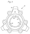
- Three channels 18, 20, 22 are formed in the outer pipe 14, which is made of a weldable alloy in the investment casting process or in the forging process, and are designed to be open radially inward, facing the inner pipe 12 (cf. also FIG. 3 ).
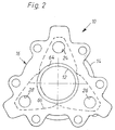
- the channels 18, 20, 22 expand radially outward toward the flange 16, as can be seen in the sectional view in FIG. 1 with reference to the channel 18, and open into recesses 24, 26, 28 of the flange 16 that can be seen in FIG. 2 ,
- the flange 16 is by means of screws, not shown, with one component connected, which is a drive part 30 of a preferred use not shown speed change gear for Motor vehicle is, said recesses 24, 26, 28 with in the drive part for controlling drive ratios with three Channels 32 (only one channel 32 can be seen in the sectional view in FIG. 1) communicate.
- An axial seal, not shown, is between arranged the flange 16 and the drive part 30: the inner tube 12 protrudes with a ring section 12a with the interposition of one Ring seal 34 in a corresponding bore 36 of the drive part 30 a.
- the three channels 18, 20, 22 are arranged in a star shape around the outer tube 14 and have different lengths I 1 , I 2 , I 3 , as is illustrated in FIG. 1.
- the visible channel 18 has the length I 2 calculated from the corresponding recess 24, 26, 28, which is made up to a first feed bore 38 in the outer tube 14.
- the channel 20 not shown in FIG. 1 due to the sectional view has the length I 1 (see the dashed lines) and extends to a further feed hole 40 in the outer tube 14.
- the third channel 22 is continuously open up to the end face of the outer tube 14 and thus has the length I 3 .
- These channels can preferably have a radially flat cross section.
- the externally rotationally symmetrical section 14a of the outer tube 14 has piston rings 44 inserted in ring grooves 42 and is in a Bore 46 of a housing component or of the gear housing 48 of the speed change gearbox used.
- the piston rings 44 are located on both sides of the housing Feed and / or discharge channels 50, 52, the ring-side through the housing channels 54, 56 communicate with the feed bores 38, 40.
- An opposite ring section 12b of the inner tube also projects 12 axially beyond the outer tube 14 and is by means of a in the housing bore 46 used sealing ring 58 sealed, whereby the front open channel 22 without leakage with the other Feed or discharge channel 60 can communicate.
- the inner tube 12 is through a steel tube with a corresponding surface finish formed in the area of the shaft sealing ring 58 and tight in the outer tube 14 inserted into its inner bore 62.
- the inner tube 12 is ring-shaped by laser beam welding the flange 16 and the outer tube 14 welded (weld 64).
- the flange 16 is tightly connected in a star shape in accordance with the outer configuration of the outer tube 14 in the flange region by laser beam welding.
- fluid or hydraulic oil under pressure can be supplied and / or removed to the drive part 30 separately.
- the inner tube 12 of the fluid supply part 10 encloses a transmission shaft, not shown, which is operatively connected to the drive part 30.
Landscapes
- Engineering & Computer Science (AREA)
- General Engineering & Computer Science (AREA)
- Mechanical Engineering (AREA)
- General Details Of Gearings (AREA)
Abstract
Description
- Fig. 1
- einen Längsschnitt durch ein Fluidführungsteil mit einem Außenrohr, einem Innenrohr und einem stirnseitigem Flansch, sowie mit einem teilweise angedeutetem Antriebsteil und einem Gehäuse-Bauteil eines Geschwindigkeits-Wechselgetriebes für Kraftfahrzeuge;
- Fig. 2
- eine Ansicht X auf den stirnseitigen Flansch des Fluidführungsteils gemäß Fig. 1; und
- Fig. 3
- eine weitere Ansicht Y des Fluidführungsteils auf dessen gegenüberliegende Stirnseite.
Claims (15)
- Rohrförmiges Fluidführungsteil, das in der Rohrwand Kanäle zum axialer Führen eines Fluids von einem Bauteil zu einem anderen Bauteil aufweist, dadurch gekennzeichnet, dass es zumindest aus einem Innenrohr (12) und einem dieses umgebenden Außenrohr (14) besteht, wobei die Kanäle (18, 20, 22) durch offene Nuten im Innenrohr und/oder Außenrohr gebildet sind, die in einen stirnseitigen Flansch (16) und/oder in radiale Fluidführungsbohrungen (38, 40) münden.
- Fluidführungsteil nach Anspruch 1, dadurch gekennzeichnet, dass die offenen Nuten ausschließlich im Außenrohr (14) ausgebildet sind und dass das Innenrohr (12) rotationssymmetrisch ausgeführt ist.
- Fluidführungsteil nach den Ansprüchen 1 und 2, dadurch gekennzeichnet, dass an dessen einer Stirnseite ein Flansch (16) angeordnet ist, der fluiddicht mit dem Außenrohr (14) und dem Innenrohr (12) verbunden ist und der zumindest eine Ausnehmung (24, 26, 28) für das Fluid aufweist.
- Fluidführungsteil nach den Ansprüchen 1 bis 3, dadurch gekennzeichnet, dass der Flansch (16) stirnseitig mit dem Außenrohr (14) und dem Innenrohr (12) dicht verschweißt ist.
- Fluidführungsteil nach Anspruch 4, dadurch gekennzeichnet, dass der Flansch (16) mit dem Außenrohr (14) und dem Innenrohr (12) durch Strahlschweißen, insbesondere durch Laserstrahlschweißen, verbunden ist.
- Fluidführungsteil nach einem oder mehreren der Ansprüche 1 bis 5, dadurch gekennzeichnet, dass das Außenrohr (14) mit mehreren, durch offene Nuten gebildeten Kanälen (18, 20, 22) versehen ist, die mit separaten Zuführbohrungen (38, 40, 60) und/oder Ausnehmungen (24, 26, 28) im Flansch (16) kommunizieren.
- Fluidführungsteil nach einem oder mehreren der Ansprüche 1 bis 6, dadurch gekennzeichnet, dass das Außenrohr (14) flanschseitig zumindest im Bereich der offenen Nuten radial nach außen erweitert ist.
- Fluidführungsteil nach einem oder mehreren der Ansprüche 1 bis 7, dadurch gekennzeichnet, dass drei durch offene Nuten im Außenrohr (14) gebildete Kanäle (18, 20, 22) vorgesehen sind, die sternförmig um den Umfang verteilt in die Ausnehmungen (24, 26, 28) im Flansch (16) münden.
- Fluidführungsteil nach einem oder mehreren der vorhergehenden Ansprüche, dadurch gekennzeichnet, dass das rotationssymmetrische Innenrohr (12) das Außenrohr (14) zumindest an einer Stirnseite überragt und in einer Bohrung (36, 46) eines angrenzenden Bauteiles (30, 48) abgedichtet ist.
- Fluidführungsteil nach Anspruch 9, dadurch gekennzeichnet, dass ein in dem Außenrohr (14) ausgeführter Kanal (22) an der dem Flansch (16) gegenüberliegenden Stirnseite offen ausgebildet ist.
- Fluidführungsteil nach einem oder mehreren der vorhergehenden Ansprüche, dadurch gekennzeichnet, dass das Außenrohr (14) im Gießverfahren oder im Schmiedeverfahren hergestellt ist.
- Fluidführungsteil nach einem oder mehreren der vorhergehenden Ansprüche, dadurch gekennzeichnet, dass die Kanäle (18, 20, 22) unterschiedlich lang (I1, I2, I3) ausgebildet sind und dass die radialen Zuführbohrungen (38, 40) jeweils zwischen an dem Außenrohr (14) angeordneten Dichtringen (44) eingebracht sind.
- Fluidführungsteil nach Anspruch 12, dadurch gekennzeichnet, dass die Dichtringe in Ringnuten (42) des Außenrohres (14) eingesetzte Kolbenringe (44) oder ähnliche Dichtelemente sind.
- Verwendung eines Fluidführungsteiles nach einem oder mehreren der vorhergehenden Ansprüche, dadurch gekennzeichnet, dass es mit einem rotierendem Teil (30) eines Geschwindigkeits-Wechselgetriebes für Kraftfahrzeuge mittels des Flansches (16) verbunden ist und dass das Außenrohr (14) in eine zylindrische Bohrung (46) in einem benachbartem Gehäuse (48) des Wechselgetriebes eingesteckt ist, wobei mit den radialen Zuführbohrungen (38, 40) und den Ausnehmungen (24, 26, 28) im Flansch (16) kommunizierende Zulauf- und Ablaufkanäle (32, 50, 52, 60) vorgesehen sind.
- Verwendung nach Anspruch 14, dadurch gekennzeichnet, dass das Fluidführungsteil (10) um eine Getriebewelle des Wechselgetriebes angeordnet ist und Hydrauliköl vom Gehäuse (48) zum rotierenden Teil (30) des Wechselgetriebes zum Steuern von Antriebsübersetzungen leitet.
Applications Claiming Priority (2)
| Application Number | Priority Date | Filing Date | Title |
|---|---|---|---|
| DE2002155538 DE10255538B4 (de) | 2002-11-28 | 2002-11-28 | Rohrförmiges Fluidführungsteil eines Geschwindigkeitstest-Wechselgetriebes eines Kraftfahrzeuges |
| DE10255538 | 2002-11-28 |
Publications (2)
| Publication Number | Publication Date |
|---|---|
| EP1424521A1 true EP1424521A1 (de) | 2004-06-02 |
| EP1424521B1 EP1424521B1 (de) | 2006-08-30 |
Family
ID=32240496
Family Applications (1)
| Application Number | Title | Priority Date | Filing Date |
|---|---|---|---|
| EP20030024823 Expired - Lifetime EP1424521B1 (de) | 2002-11-28 | 2003-10-31 | Rohrförmiges Fluidführungsteil |
Country Status (2)
| Country | Link |
|---|---|
| EP (1) | EP1424521B1 (de) |
| DE (2) | DE10255538B4 (de) |
Cited By (1)
| Publication number | Priority date | Publication date | Assignee | Title |
|---|---|---|---|---|
| CN113167372A (zh) * | 2018-11-29 | 2021-07-23 | 采埃孚股份公司 | 排油槽 |
Citations (6)
| Publication number | Priority date | Publication date | Assignee | Title |
|---|---|---|---|---|
| FR2501823A1 (fr) * | 1981-03-13 | 1982-09-17 | Ardennes Equipements | Dispositif de fixation et d'alimentation d'un equipement hydraulique de manutention a un engin de levage |
| EP0148813A2 (de) * | 1984-01-12 | 1985-07-17 | Contigea Schlumberger S.A. | Dichtung |
| EP0207015A2 (de) * | 1985-06-18 | 1986-12-30 | DITTA PACETTI ANTONIO di Silvano & Andrea Pacetti | Belüfteter Kollektor für ein Gasverteilungsnetz für Haushalt- oder andere Benutzer |
| DE4423201A1 (de) * | 1993-07-10 | 1995-01-12 | Barmag Barmer Maschf | Rohrflanschverbindung |
| US5400828A (en) * | 1993-07-08 | 1995-03-28 | Christopher G. Ziu | Double-containment piping supports for improved annulus flow |
| GB2324845A (en) * | 1997-05-02 | 1998-11-04 | Castrol Ltd | Pipeline joint for double-skinned pipes |
Family Cites Families (2)
| Publication number | Priority date | Publication date | Assignee | Title |
|---|---|---|---|---|
| JPS6242728A (ja) * | 1985-08-14 | 1987-02-24 | Ono Bankin Kogyosho:Kk | 流体混合具 |
| ATE211022T1 (de) * | 1996-06-11 | 2002-01-15 | Smithkline Beecham Consumer | Misch- und abgabevorrichtung |
-
2002
- 2002-11-28 DE DE2002155538 patent/DE10255538B4/de not_active Expired - Lifetime
-
2003
- 2003-10-31 DE DE50304837T patent/DE50304837D1/de not_active Expired - Lifetime
- 2003-10-31 EP EP20030024823 patent/EP1424521B1/de not_active Expired - Lifetime
Patent Citations (6)
| Publication number | Priority date | Publication date | Assignee | Title |
|---|---|---|---|---|
| FR2501823A1 (fr) * | 1981-03-13 | 1982-09-17 | Ardennes Equipements | Dispositif de fixation et d'alimentation d'un equipement hydraulique de manutention a un engin de levage |
| EP0148813A2 (de) * | 1984-01-12 | 1985-07-17 | Contigea Schlumberger S.A. | Dichtung |
| EP0207015A2 (de) * | 1985-06-18 | 1986-12-30 | DITTA PACETTI ANTONIO di Silvano & Andrea Pacetti | Belüfteter Kollektor für ein Gasverteilungsnetz für Haushalt- oder andere Benutzer |
| US5400828A (en) * | 1993-07-08 | 1995-03-28 | Christopher G. Ziu | Double-containment piping supports for improved annulus flow |
| DE4423201A1 (de) * | 1993-07-10 | 1995-01-12 | Barmag Barmer Maschf | Rohrflanschverbindung |
| GB2324845A (en) * | 1997-05-02 | 1998-11-04 | Castrol Ltd | Pipeline joint for double-skinned pipes |
Cited By (1)
| Publication number | Priority date | Publication date | Assignee | Title |
|---|---|---|---|---|
| CN113167372A (zh) * | 2018-11-29 | 2021-07-23 | 采埃孚股份公司 | 排油槽 |
Also Published As
| Publication number | Publication date |
|---|---|
| DE10255538B4 (de) | 2006-02-09 |
| DE50304837D1 (de) | 2006-10-12 |
| EP1424521B1 (de) | 2006-08-30 |
| DE10255538A1 (de) | 2004-06-17 |
Similar Documents
| Publication | Publication Date | Title |
|---|---|---|
| DE2720130C3 (de) | Meißeldirektantrieb für Tiefbohrwerkzeuge | |
| DE102008063385B4 (de) | Kupplungssupport | |
| WO2001007762A1 (de) | Hohlwelle mit innenkanälen, insbesondere ölkanälen | |
| EP1646812A1 (de) | Ölführende welle | |
| DE3409541A1 (de) | Hohlwelle zur uebertragung von drehmomenten | |
| DE69901826T2 (de) | Vorrichtung zur steuerung von rollen für ein stufenloses getriebe | |
| CH622599A5 (en) | Process and device for fastening a sleeve in a fluid pipeline | |
| CH630828A5 (de) | Tiefbohrwerkzeug. | |
| DE602004001541T2 (de) | Schnecke mit Wärmetauschfunktion, Mischer und Extruder | |
| EP4072737B1 (de) | Reinigungsvorrichtung | |
| DE3245840C2 (de) | Vorrichtung zur Zuführung von Hydraulikflüssigkeit zu mindestens einer hydraulisch betätigten Kupplung | |
| EP1129292B1 (de) | Schnecke für eine exzenterschneckenpumpe oder einen untertagebohrmotor | |
| DE3324035A1 (de) | Anordnung mit einem arbeitszylinder mit beiderseitigen kolbenstangen, insbesondere fuer servolenkgetriebe, und verfahren zu seiner herstellung | |
| EP1988343A2 (de) | Anschlusselement für einen Heizkörper | |
| EP1247005B1 (de) | Welle als maschinenbauteil mit integrierten leitungen | |
| EP1424521B1 (de) | Rohrförmiges Fluidführungsteil | |
| DE1068803B (de) | ||
| DE102005028087B4 (de) | Vorrichtung zur Abdichtung eines Vakuumtankes | |
| EP1316746A2 (de) | Automatgetriebe | |
| DE102005028818B3 (de) | Stator für eine Exzenterschneckenpumpe und Verfahren zu seiner Herstellung | |
| DE10142442B4 (de) | Gehäuse | |
| EP0574682B1 (de) | Kupplung zum reibschlüssigen Verbinden einer Welle mit einem Maschinenteil | |
| DE19629218B4 (de) | Ventilkolben für ein als 4/3-Wege-Ventil ausgebildetes lineares Schieberventil | |
| DE102008032771B4 (de) | Verteilervorrichtung für hydraulische Systeme | |
| DE10243697A1 (de) | Schwenkmotor |
Legal Events
| Date | Code | Title | Description |
|---|---|---|---|
| PUAI | Public reference made under article 153(3) epc to a published international application that has entered the european phase |
Free format text: ORIGINAL CODE: 0009012 |
|
| 17P | Request for examination filed |
Effective date: 20040220 |
|
| AK | Designated contracting states |
Kind code of ref document: A1 Designated state(s): AT BE BG CH CY CZ DE DK EE ES FI FR GB GR HU IE IT LI LU MC NL PT RO SE SI SK TR |
|
| AX | Request for extension of the european patent |
Extension state: AL LT LV MK |
|
| 17Q | First examination report despatched |
Effective date: 20040803 |
|
| AKX | Designation fees paid |
Designated state(s): DE FR GB IT |
|
| GRAP | Despatch of communication of intention to grant a patent |
Free format text: ORIGINAL CODE: EPIDOSNIGR1 |
|
| GRAS | Grant fee paid |
Free format text: ORIGINAL CODE: EPIDOSNIGR3 |
|
| GRAA | (expected) grant |
Free format text: ORIGINAL CODE: 0009210 |
|
| AK | Designated contracting states |
Kind code of ref document: B1 Designated state(s): DE FR GB IT |
|
| PG25 | Lapsed in a contracting state [announced via postgrant information from national office to epo] |
Ref country code: IT Free format text: LAPSE BECAUSE OF FAILURE TO SUBMIT A TRANSLATION OF THE DESCRIPTION OR TO PAY THE FEE WITHIN THE PRESCRIBED TIME-LIMIT;WARNING: LAPSES OF ITALIAN PATENTS WITH EFFECTIVE DATE BEFORE 2007 MAY HAVE OCCURRED AT ANY TIME BEFORE 2007. THE CORRECT EFFECTIVE DATE MAY BE DIFFERENT FROM THE ONE RECORDED. Effective date: 20060830 |
|
| REG | Reference to a national code |
Ref country code: GB Ref legal event code: FG4D Free format text: NOT ENGLISH |
|
| REF | Corresponds to: |
Ref document number: 50304837 Country of ref document: DE Date of ref document: 20061012 Kind code of ref document: P |
|
| GBT | Gb: translation of ep patent filed (gb section 77(6)(a)/1977) |
Effective date: 20061004 |
|
| ET | Fr: translation filed | ||
| PLBE | No opposition filed within time limit |
Free format text: ORIGINAL CODE: 0009261 |
|
| STAA | Information on the status of an ep patent application or granted ep patent |
Free format text: STATUS: NO OPPOSITION FILED WITHIN TIME LIMIT |
|
| 26N | No opposition filed |
Effective date: 20070531 |
|
| REG | Reference to a national code |
Ref country code: FR Ref legal event code: PLFP Year of fee payment: 13 |
|
| REG | Reference to a national code |
Ref country code: FR Ref legal event code: PLFP Year of fee payment: 14 |
|
| REG | Reference to a national code |
Ref country code: FR Ref legal event code: PLFP Year of fee payment: 15 |
|
| REG | Reference to a national code |
Ref country code: FR Ref legal event code: PLFP Year of fee payment: 16 |
|
| PGFP | Annual fee paid to national office [announced via postgrant information from national office to epo] |
Ref country code: DE Payment date: 20181031 Year of fee payment: 16 |
|
| PGFP | Annual fee paid to national office [announced via postgrant information from national office to epo] |
Ref country code: GB Payment date: 20181024 Year of fee payment: 16 Ref country code: IT Payment date: 20181031 Year of fee payment: 16 Ref country code: FR Payment date: 20181026 Year of fee payment: 16 |
|
| REG | Reference to a national code |
Ref country code: DE Ref legal event code: R119 Ref document number: 50304837 Country of ref document: DE |
|
| PG25 | Lapsed in a contracting state [announced via postgrant information from national office to epo] |
Ref country code: DE Free format text: LAPSE BECAUSE OF NON-PAYMENT OF DUE FEES Effective date: 20200501 |
|
| GBPC | Gb: european patent ceased through non-payment of renewal fee |
Effective date: 20191031 |
|
| PG25 | Lapsed in a contracting state [announced via postgrant information from national office to epo] |
Ref country code: GB Free format text: LAPSE BECAUSE OF NON-PAYMENT OF DUE FEES Effective date: 20191031 Ref country code: IT Free format text: LAPSE BECAUSE OF NON-PAYMENT OF DUE FEES Effective date: 20191031 Ref country code: FR Free format text: LAPSE BECAUSE OF NON-PAYMENT OF DUE FEES Effective date: 20191031 |