EP1424000B1 - Ballenentladevorrichtung einer Rundballenpresse - Google Patents
Ballenentladevorrichtung einer Rundballenpresse Download PDFInfo
- Publication number
- EP1424000B1 EP1424000B1 EP03025590A EP03025590A EP1424000B1 EP 1424000 B1 EP1424000 B1 EP 1424000B1 EP 03025590 A EP03025590 A EP 03025590A EP 03025590 A EP03025590 A EP 03025590A EP 1424000 B1 EP1424000 B1 EP 1424000B1
- Authority
- EP
- European Patent Office
- Prior art keywords
- bale
- carrier
- unloading device
- round
- holder
- Prior art date
- Legal status (The legal status is an assumption and is not a legal conclusion. Google has not performed a legal analysis and makes no representation as to the accuracy of the status listed.)
- Expired - Lifetime
Links
- 230000008021 deposition Effects 0.000 claims abstract description 3
- 230000033001 locomotion Effects 0.000 claims description 14
- 238000005096 rolling process Methods 0.000 claims description 12
- 238000007493 shaping process Methods 0.000 claims 1
- 238000005303 weighing Methods 0.000 claims 1
- 230000005484 gravity Effects 0.000 description 2
- 239000000969 carrier Substances 0.000 description 1
- 230000006835 compression Effects 0.000 description 1
- 238000007906 compression Methods 0.000 description 1
- 238000010276 construction Methods 0.000 description 1
- 230000001419 dependent effect Effects 0.000 description 1
- 238000011161 development Methods 0.000 description 1
- 230000018109 developmental process Effects 0.000 description 1
- 239000007787 solid Substances 0.000 description 1
Images

Classifications
-
- A—HUMAN NECESSITIES
- A01—AGRICULTURE; FORESTRY; ANIMAL HUSBANDRY; HUNTING; TRAPPING; FISHING
- A01F—PROCESSING OF HARVESTED PRODUCE; HAY OR STRAW PRESSES; DEVICES FOR STORING AGRICULTURAL OR HORTICULTURAL PRODUCE
- A01F15/00—Baling presses for straw, hay or the like
- A01F15/08—Details
- A01F15/0875—Discharge devices
- A01F15/0883—Discharge devices for round balers
-
- A—HUMAN NECESSITIES
- A01—AGRICULTURE; FORESTRY; ANIMAL HUSBANDRY; HUNTING; TRAPPING; FISHING
- A01F—PROCESSING OF HARVESTED PRODUCE; HAY OR STRAW PRESSES; DEVICES FOR STORING AGRICULTURAL OR HORTICULTURAL PRODUCE
- A01F15/00—Baling presses for straw, hay or the like
- A01F15/08—Details
- A01F15/0875—Discharge devices
- A01F2015/0891—Weighing the finished bale before falling to ground
Definitions
- the invention relates to a bale unloading device of a round baler with a carrier and a bale picker.
- the round bales can be picked up by the bale pick-up after or when leaving the pressing chamber and can be moved away from the bale chamber with it without having to roll itself.
- the height-adjustable support may be controlled or approached the ground due to gravity and may tip over the bale from the bale receiver or the like.
- the carrier can be on or off multi-arm trained and pivoted, parallelogram or linearly adjusted in height.
- the bale picker can roll on the carrier, be moved or swiveled. In any case, it is avoided that the round bale down a ramp and due to its kinetic energy z. B. rolls down a slope.
- the technically simplest way to move the carrier vertically is the use of a pivoting movement. This is controlled by external force, so that the weight of the round bale does not exert the unloading unaffected.
- a horizontal movement of the carrier has the advantage that the round bales can be stored not only behind, but also laterally of the round baler. Another advantage is that the round bale thereby moved quickly out of the range of movement of an outlet flap and this can be lowered immediately after the outlet of the round bale.
- the horizontal movement can be achieved both by means of a pivoting movement as well as translational.
- the storage of the Ballenaufsmellings by means of rolling elements has the advantage that it can move alone due to gravity at a suitable inclination between its end positions, which z. B. would be more difficult in a sliding bearing.
- rolling elements rollers, wheels, etc. can be used.
- a guide for the rolling elements is provided in, on or on the carrier or a plurality of carriers.
- the round bale can be placed on the ground as it was accepted by the press room; its longitudinal center axis can also be pivoted by 90 degrees in the horizontal; Finally, it can be stored laterally on its front side, whereby a rolling motion is reliably avoided.
- the weight of the round bale can be easily determined if it rests alone on the bale picker or tipped over its edge.
- the load peak measured with the latter is a sure measure of the weight.
- sensors for the bale picker makes it possible to detect whether the bale picker is even in a bale picking position and / or whether the round bale has really been deposited on the ground.
- mechanical motion sensors as well as non-contact sensors can be used.
- the unloading of the round bale can take place in that the carrier guides the bale picker in a predetermined path, z. B. a laterally inclined path or a tipping at the end of the web.
- the carrier contains at least one rail, there is a solid support for the round bale, although two rails provide even safer guidance for the bale picker.
- telescoping can lead to a short construction and, on the other hand, to a deposit of the round bale far from the final loading opening.
- a round baler 10 which has a front compression housing 12, a rear pivot housing 14, an axle 16 with wheels 18, a drawbar 20, a receiving device 22 and a bale discharge device 24 according to the invention.
- the round baler 10 is shown very simplified, since it depends on their structure, function and details only, as far as will be described below, while the rest can be formed in a variety and well-known manner. Essentially, it is important that a round bale 26 formed in the round baler 10 is laid down gently on the ground, so that attention is directed to the bale unloading device 24, which can be retrofitted to existing round balers 10 of various designs.
- the front press housing 12 opens with the swivel housing 14 raised to the rear and forms a lower rear edge 28 slightly above the axis 16, over which the round bale 26 rolls to the rear from an unspecified press room.
- the rear pivot housing 14 is vertically pivotable and, in an upper position, releases the pressing space so that the round bale 26 can escape to the rear. In a lowered position, not shown, it is located slightly above the bale unloading device 24th
- the axle 16 extends transversely to the direction of travel and serves to receive the bale unloading device 24 in its front end region.
- the wheels 18 are located at the outer end portions of the axle 16, support the round baler 10 movable on the ground and take between the press housing 12 and the pivot housing 14 on.
- the drawbar 20 is used to connect the round baler 10 to a towing vehicle, not shown, and prevents their tilting about the axis 16 during the movement of the round bale 26th
- the receiving device 22 picks up the crop from the ground and promotes it to the rear and top of the press room, optionally via a cutting device and a cross conveyor.
- the bale unloading device 24 includes a carrier 30 and a bale receiver 32 and serves to deposit or set down a round bale 26 emerging from the pressing space, without giving it a substantial rolling movement. Consequently, the bale unloading device 24 is located adjacent to the rear edge 28 and below the pivot housing 14 in a position that allows the inclusion of the round bale 26.
- the carrier 30 includes in this embodiment, two rails 34 and a cross member 36, which are rigid, although possibly detachable, connected to each other and can pivot together.
- the rails 34 are formed as U-rails, the interior of which opens horizontally outwards. Starting from the front, ie in FIG. 3 from the right, the rails 34 extend straight over about 5/6 of their length, while the last sixth falls back and down at an angle of about 45 degrees to the ground. Both rails 34 are parallel to each other and in a non-operating position relatively parallel to the ground.
- rails 34 can be used and that the interior can also open inwardly and / or that the rails 34 may have a different profile or a different cross-section, as long as a sliding or Rolling movement of the bale receiver 32 is possible on them.
- the rails 34 may also be formed telescopically.
- the crossbar 36 is connected by means of bearings 38 to the axis 16 vertically pivotable and extends parallel to this. Preferably, it is designed as a tube with a round cross-section.
- the traverse 36 thus serves the vertically pivotable articulation of the rails 34 and thus the bale unloading device 24 on the round baler 10.
- the cross member 36 can also be omitted and the rail (s) 34 directly be mounted vertically pivotable on the axis 16 or on the press housing 12.
- the bale receiver 32 is substantially formed as a carriage or carriage which is movably guided on, in or on the carrier 30.
- the bale picker 32 has a loading surface 40 and rolling elements 42.
- the loading surface 40 is designed so large that it can store a round bale 26 safely and has a transverse to the direction of movement of the bale receiver 32 trough, which prevents the round bale 26 from rolling down.
- the rolling elements 42 are at the bottom of the loading area 40, z. B. in yokes, rails or other unspecified holders rotatably received and are used in the interiors of the rails 34, in which they are movable. In the assembled state, therefore, the loading area 40 along the rails 34 can be moved captive.
- a control device 44 is provided for the movement of the bale unloading device 24.
- This is executed in the simplest and used here embodiment as a spring which acts between the carrier 30, in particular its rails 34, and the round baler 10, in particular the axis 16, and the carrier 30 is always urging upward.
- This control works as follows: The bale unloading device 24 is pushed up by the control device 44 and receives the rolling over the rear edge 28 round bale 26 which settles in the trough. Once the pivot housing 14 is opened wide enough that the weight of the round bale 26 can act unimpeded on the bale unloading device 24, the carrier 30 will move with the bale receiver 32 against the action of the control device 44 down.
- the bale picker 32 will slide to the rear and thereby transport the round bales 26 dormant. Finally, the downwardly angled end portion of the rails 34 will contact the ground and tilt the bale receiver 32, resulting in the deposition of the round bale 26. Since in this position, the bale picker 32 is located directly above the ground, the round bale 26 is more deposited or stored as rolled down. As a result, the round bale 26 remains and rolls neither an inclined surface nor unwrapped wound on him yarn.
Landscapes
- Life Sciences & Earth Sciences (AREA)
- Environmental Sciences (AREA)
- Storage Of Harvested Produce (AREA)
- Harvester Elements (AREA)
- Press Drives And Press Lines (AREA)
- Preliminary Treatment Of Fibers (AREA)
- Specific Conveyance Elements (AREA)
Description
- Die Erfindung betrifft eine Ballenentladevorrichtung einer Rundballenpresse mit einem Träger und einem Ballenaufnehmer.
- Im Stand der Technik (
DE 33 04 518 C2 ) bekannte Ballenentladevorrichtungen bestehen aus Rampen, die vertikal schwenkbar an dem Rahmen oder der Achse einer Rundballenpresse angebracht sind und sich aufgrund des Gewichts eines ausgeworfenen Rundballens zum Boden absenken. Ein darauf abgelegter Rundballen rollt hinunter. Gegebenenfalls wird mittels Federn verhindert, dass die Rampen zu schnell absinken, um die Rollbewegung abzubremsen. - Das der Erfindung zugrundeliegende Problem wird darin gesehen, dass insbesondere auf abschüssigem Gelände der Rundballen unkontrolliert wegrollen kann.
- Dieses Problem wird in erfinderischer Weise durch die Lehre von Patentanspruch 1 gelöst, wobei in den davon abhängigen Patentansprüchen jeweils vorteilhafte Weiterentwicklungen gelehrt werden.
- Auf diese Weise kann der Rundballen nach dem oder beim Verlassen der Presskammer von dem Ballenaufnehmer aufgenommen und mit diesem von dem Pressraum wegbewegt werden, ohne selbst rollen zu müssen. Der höhenbewegliche Träger kann sich gesteuert oder aufgrund der Schwerkraft dem Boden nähern und den Ballen von dem Ballenaufnehmer abkippen oder dergleichen. Der Träger kann ein- oder mehrarmig ausgebildet und schwenkbar, parallelogrammartig oder linear in der Höhe verstellt werden. Der Ballenaufnehmer kann auf dem Träger abrollen, verschoben oder geschwenkt werden. In jedem Fall wird vermieden, dass der Rundballen eine Rampe hinunter und aufgrund seiner Bewegungsenergie z. B. einen Hang hinab rollt.
- Die technisch einfachste Art, den Träger vertikal zu bewegen, besteht in der Nutzung einer Schwenkbewegung. Diese wird mittels Fremdkraft gesteuert, damit das Gewicht des Rundballens den Entladevorgang nicht unbeeinflusst ausübt.
- Eine horizontale Bewegung des Trägers hat den Vorteil, dass der Rundballen nicht nur hinter, sondern auch seitlich der Rundballenpresse abgelegt werden kann. Ein weiterer Vorteil liegt darin, dass der Rundballen dadurch schnell aus dem Bewegungsbereich einer Auslassklappe herausbewegt und diese sofort nach dem Auslass des Rundballens abgesenkt werden kann. Die horizontale Bewegung kann sowohl mittels einer Schwenkbewegung als auch translatorisch erzielt werden.
- Die Lagerung des Ballenaufnehmers mittels Wälzkörpern hat den Vorteil, dass sich dieser alleine aufgrund der Schwerkraft bei entsprechender Neigung zwischen seinen Endstellungen bewegen kann, was z. B. bei einer Gleitlagerung schwieriger wäre. Als Wälzkörper können Rollen, Räder, etc. verwendet werden. Vorzugsweise ist in, an oder auf dem Träger bzw. mehreren Trägern eine Führung für die Wälzkörper vorgesehen.
- Der Rundballen kann so auf den Boden abgelegt werden wie er von dem Pressraum angenommen wurde; seine Längsmittenachse kann aber auch um 90 Grad in der Horizontalen geschwenkt werden; schließlich kann er auf seiner Stirnseite seitlich abgelegt werden, wodurch eine Wegrollbewegung zuverlässig vermieden wird.
- Das Gewicht des Rundballens kann leicht ermittelt werden, wenn dieser alleine auf dem Ballenaufnehmer ruht oder über dessen Kante abgekippt wird. Die bei letzterem gemessene Lastspitze ist ein sicheres Maß für das Gewicht.
- Die Verwendung von Sensoren für den Ballenaufnehmer macht es möglich zu erkennen, ob sich der Ballenaufnehmer überhaupt in einer Ballenannahmestellung befindet und/oder ob der Rundballen wirklich auf dem Boden abgelegt wurde. Hierfür können mechanische Bewegungssensoren wie auch berührungslose Sensoren verwendet werden.
- Das Entladen des Rundballens kann dadurch erfolgen, dass der Träger den Ballenaufnehmer in einer vorbestimmten Bahn führt, z. B. eine seitlich geneigt Bahn oder eine am Ablageende abkippende Bahn.
- Wenn der Träger wenigstens eine Schiene enthält, ist eine massive Abstützung für den Rundballen gegeben, wenn auch zwei Schienen eine noch sicherere Führung für den Ballenaufnehmer bieten. Eine Teleskopierbarkeit kann einerseits zu einer kurzen Bauweise und andererseits zu einer Ablage des Rundballens weit von der Endladeöffnung führen.
- In der Zeichnung ist ein nachfolgend näher beschriebenes Ausführungsbeispiel der Erfindung offenbart. Es zeigt:
- Figur 1
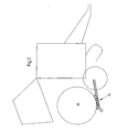
- eine Rundballenpresse mit einer erfindungsgemäßen Ballenentladevorrichtung in einer Aufnahmesituation in Seitenansicht und schematischer Darstellung,
- Figur 2
- die Rundballenpresse nach
Figur 1 mit der Ballenentladevorrichtung nahe einer Abgabesituation und - Figur 3
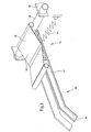
- die Ballenentladevorrichtung in einer perspektivischen Darstellung.
- In der Zeichnung ist eine Rundballenpresse 10 dargestellt, die ein vorderes Pressgehäuse 12, ein rückwärtiges Schwenkgehäuse 14, eine Achse 16 mit Rädern 18, eine Deichsel 20, eine Aufnahmevorrichtung 22 und eine erfindungsgemäße Ballenentladevorrichtung 24 aufweist.
- Die Rundballenpresse 10 ist sehr vereinfacht dargestellt, da es auf deren Aufbau, Funktion und Einzelheiten nur ankommt, soweit dies im folgenden beschrieben wird, während der Rest in vielfältiger und bekannter Weise ausgebildet werden kann. Im Wesentlichen geht es darum, dass ein in der Rundballenpresse 10 gebildeter Rundballen 26 schonend auf den Boden abgelegt wird, sodass sich das Augenmerk auf die Ballenentladevorrichtung 24 richtet, die nachträglich an bestehende Rundballenpressen 10 verschiedenster Bauart angebaut werden kann.
- Das vordere Pressgehäuse 12 öffnet sich bei angehobenem Schwenkgehäuse 14 nach hinten und bildet eine untere rückwärtige Kante 28 leicht oberhalb der Achse 16, über die der Rundballen 26 nach hinten aus einem nicht näher bezeichneten Pressraum rollt.
- Das rückwärtige Schwenkgehäuse 14 ist vertikal schwenkbar und gibt in einer oberen Stellung den Pressraum frei, so dass der Rundballen 26 nach hinten entweichen kann. In einer nicht dargestellten abgesenkten Stellung befindet es sich geringfügig oberhalb der Ballenentladevorrichtung 24.
- Die Achse 16 erstreckt sich quer zu der Fahrtrichtung und dient der Aufnahme der Ballenentladevorrichtung 24 in deren vorderen Endbereich.
- Die Räder 18 befinden sich an den äußeren Endbereichen der Achse 16, stützen die Rundballenpresse 10 auf dem Boden beweglich ab und nehmen zwischen sich das Pressgehäuse 12 und das Schwenkgehäuse 14 auf.
- Die Deichsel 20 dient dem Anschluss der Rundballenpresse 10 an einem nicht dargestellten Zugfahrzeug und verhindert deren Kippen um die Achse 16 bei der Bewegung des Rundballens 26.
- Die Aufnahmevorrichtung 22 nimmt das Erntegut vom Boden auf und fördert es nach hinten und oben in den Pressraum, gegebenenfalls über eine Schneidvorrichtung und einen Querförderer.
- Die Ballenentladevorrichtung 24 enthält einen Träger 30 und einen Ballenaufnehmer 32 und dient dazu, einen aus dem Pressraum austretenden Rundballen 26 auf den Boden abzulegen bzw. abzusetzen, ohne ihm eine wesentliche Rollbewegung zu verleihen. Folglich befindet sich die Ballenentladevorrichtung 24 im Anschluss an die rückwärtige Kante 28 und unterhalb des Schwenkgehäuses 14 in einer Stellung, die die Aufnahme des Rundballens 26 zulässt.
- Der Träger 30 enthält in diesem Ausführungsbeispiel zwei Schienen 34 und eine Traverse 36, die starr, wenn auch eventuell lösbar, miteinander verbunden sind und gemeinsam schwenken können.
- Die Schienen 34 sind als U-Schienen ausgebildet, deren Innenraum sich horizontal nach außen öffnet. Beginnend von vorne, d. h. in
Figur 3 von rechts, erstrecken sich die Schienen 34 über circa 5/6 ihrer Länge gerade, während das letzte Sechstel nach hinten und unten unter einem Winkel von circa 45 Grad zum Boden' hin abfällt. Beide Schienen 34 verlaufen zueinander parallel und in einer Außerbetriebsstellung relativ parallel zum Boden. - Es wird darauf hingewiesen, dass auch mehr oder weniger als zwei Schienen 34 verwendet werden können und dass sich der Innenraum auch nach innen öffnen kann und/oder, dass die Schienen 34 ein anderes Profil, bzw. einen anderen Querschnitt aufweisen können, solange eine Gleitoder Rollbewegung des Ballenaufnehmers 32 auf ihnen möglich ist. Darüber hinaus können die Schienen 34 auch teleskopisch ausgebildet sein.
- Die Traverse 36 ist mittels Lagern 38 an die Achse 16 vertikal schwenkbar angeschlossen und verläuft zu dieser parallel. Vorzugsweise ist sie als Rohr mit einem runden Querschnitt ausgebildet. Die Traverse 36 dient somit der vertikal schwenkbaren Anlenkung der Schienen 34 und somit der Ballenentladevorrichtung 24 an der Rundballenpresse 10. In abweichenden Ausführungsbeispielen kann die Traverse 36 auch entfallen und die Schiene(n) 34 direkt vertikal schwenkbar an der Achse 16 oder auch an dem Pressgehäuse 12 angebracht sein.
- Der Ballenaufnehmer 32 ist im Wesentlichen als ein Schlitten oder Wagen ausgebildet, der auf, in oder an dem Träger 30 beweglich geführt ist. Der Ballenaufnehmer 32 weist hierzu eine Ladefläche 40 und Wälzkörper 42 auf.
- Die Ladefläche 40 ist so groß ausgelegt, dass sie einen Rundballen 26 sicher lagern kann und weist eine quer zur Bewegungsrichtung des Ballenaufnehmers 32 ausgerichtete Mulde auf, die den Rundballen 26 vom Herabrollen abhält.
- Die Wälzkörper 42 sind an der Unterseite der Ladefläche 40, z. B. in Jochs, Schienen oder sonstigen nicht näher bezeichneten Haltern drehbar aufgenommen und werden in die Innenräume der Schienen 34 eingesetzt, in denen sie beweglich sind. Im montierten Zustand kann also die Ladefläche 40 entlang der Schienen 34 unverlierbar bewegt werden.
- Schließlich ist eine Steuervorrichtung 44 für die Bewegung der Ballenentladevorrichtung 24 vorgesehen. Diese ist in der einfachsten und hier benutzten Ausführung als eine Feder ausgeführt, die zwischen dem Träger 30, insbesondere dessen Schienen 34, und der Rundballenpresse 10, insbesondere deren Achse 16, wirkt und den Träger 30 stets nach oben drängt. Diese Steuerung funktioniert wie folgt: Die Ballenentladevorrichtung 24 wird von der Steuervorrichtung 44 nach oben gedrückt und nimmt den über die rückwärtige Kante 28 abrollenden Rundballen 26 auf, der sich in der Mulde festsetzt. Sobald das Schwenkgehäuse 14 weit genug geöffnet ist, dass das Gewicht des Rundballens 26 ungehindert auf die Ballenentladevorrichtung 24 wirken kann, wird sich der Träger 30 mit dem Ballenaufnehmer 32 gegen die Wirkung der Steuervorrichtung 44 nach unten bewegen. Aufgrund der dann gegebenen Neigung des Trägers 30 wird der Ballenaufnehmer 32 nach hinten gleiten und dabei den Rundballen 26 ruhend transportieren. Schließlich wird der nach unten abgewinkelte Endbereich der Schienen 34 den Boden berühren und den Ballenaufnehmer 32 kippen, was zum Ablegen des Rundballens 26 führt. Da sich in dieser Stellung der Ballenaufnehmer 32 unmittelbar über dem Boden befindet, wird der Rundballen 26 mehr abgesetzt bzw. abgelegt als herunter gerollt. Als Folge bleibt der Rundballen 26 liegen und rollt weder eine geneigte Fläche herab noch wickelt sich auf ihn aufgewickeltes Garn ab.
Claims (10)
- Ballenentladevorrichtung (24) einer Rundballenpresse (10) mit einem Träger (30) und einem Ballenaufnehmer (32), wobei der Träger (30) an der Rundballenpresse (10) zur Ablage eines Rundballens (26) vertikal beweglich anbringbar und der Ballenaufnehmer (32) ohne Fremdkraft aufgrund der Neigung des Trägers (30) gegenüber dem Träger (30) aus einer einem Auslass eines Pressraums zugelegenen in eine diesem abgelegene Stellung beweglich ist.
- Ballenentladevorrichtung nach Anspruch 1, dadurch gekennzeichnet, dass der Träger (30) vertikal schwenkbar an einer Achse (16) oder einem Pressgehäuse (12) anbringbar ist und mittels einer Steuervorrichtung (44), insbesondere einer Feder, einem Hydraulikmotor, einem Pneumatikmotor oder dergleichen beaufschlagt wird.
- Ballenentladevorrichtung nach Anspruch 1 oder 2, dadurch gekennzeichnet, dass der Träger (30) auch horizontal beweglich ist.
- Ballenentladevorrichtung nach einem oder mehreren der vorherigen Ansprüche, dadurch gekennzeichnet, dass der Ballenaufnehmer (32) mittels Wälzkörpern (42) auf, in oder an dem Träger (30) beweglich gelagert und geführt ist.
- Ballenentladevorrichtung nach einem oder mehreren der vorherigen Ansprüche, dadurch gekennzeichnet, dass der Ballenaufnehmer (32) horizontal drehbar und/oder vertikal schwenkbar ist.
- Ballenentladevorrichtung nach einem oder mehreren der vorherigen Ansprüche, dadurch gekennzeichnet, dass der Ballenaufnehmer (32) mit einer Wiegevorrichtung versehen ist.
- Ballenentladevorrichtung nach einem oder mehreren der vorherigen Ansprüche, dadurch gekennzeichnet, dass wenigstens ein Sensor zum Erkennen der Lage des Ballenaufnehmers (32) gegenüber dem Träger (30) vorgesehen ist.
- Ballenentladevorrichtung nach einem oder mehreren der vorherigen Ansprüche, dadurch gekennzeichnet, dass die Übertragung einer Bewegung auf den Ballenaufnehmer (32) mittels Zuggliedern oder Gestänge erfolgt.
- Ballenentladevorrichtung nach einem oder mehreren der vorherigen Ansprüche, dadurch gekennzeichnet, dass der Träger (30) im ablageseitigen Bereich eine Formgebung aufweist, die zu einem Kippvorgang des Ballenaufnehmers (32) führt.
- Ballenentladevorrichtung nach einem oder mehreren der vorherigen Ansprüche, dadurch gekennzeichnet, dass der Träger (30) wenigstens eine feste oder teleskopierbare Schiene (34) enthält.
Applications Claiming Priority (2)
| Application Number | Priority Date | Filing Date | Title |
|---|---|---|---|
| DE10254954A DE10254954A1 (de) | 2002-11-26 | 2002-11-26 | Ballenentladevorrichtung einer Rundballenpresse |
| DE10254954 | 2002-11-26 |
Publications (2)
| Publication Number | Publication Date |
|---|---|
| EP1424000A1 EP1424000A1 (de) | 2004-06-02 |
| EP1424000B1 true EP1424000B1 (de) | 2010-08-18 |
Family
ID=32240391
Family Applications (1)
| Application Number | Title | Priority Date | Filing Date |
|---|---|---|---|
| EP03025590A Expired - Lifetime EP1424000B1 (de) | 2002-11-26 | 2003-11-08 | Ballenentladevorrichtung einer Rundballenpresse |
Country Status (7)
| Country | Link |
|---|---|
| US (1) | US7000533B2 (de) |
| EP (1) | EP1424000B1 (de) |
| AT (1) | ATE477708T1 (de) |
| AU (1) | AU2003262214B2 (de) |
| CA (1) | CA2450970C (de) |
| DE (2) | DE10254954A1 (de) |
| PL (1) | PL362784A1 (de) |
Families Citing this family (32)
| Publication number | Priority date | Publication date | Assignee | Title |
|---|---|---|---|---|
| EP1508268B1 (de) * | 2003-08-21 | 2017-04-12 | Lely Maschinenfabrik GmbH | Rundballenpresse |
| US7197979B2 (en) * | 2005-06-10 | 2007-04-03 | Deere & Company | Controlled bale ejection mechanism |
| DE102006038299A1 (de) * | 2006-08-16 | 2008-02-28 | Deere & Company, Moline | Rundballenpresse |
| NL1037740C2 (en) * | 2010-02-23 | 2011-08-24 | Forage Innovations Bv | Wrapper for wrapping round bales of crop material. |
| NL1037742C2 (en) * | 2010-02-23 | 2011-08-24 | Forage Innovations Bv | Wrapper for wrapping bales of crop material. |
| US8113113B2 (en) | 2010-05-04 | 2012-02-14 | Deere & Company | Discharged bale control device and control method |
| US8978549B2 (en) | 2011-09-28 | 2015-03-17 | Forage Innovations B.V. | Baler attachment for optionally changing the orientation of bales being released from a baler |
| US9297688B2 (en) | 2012-12-21 | 2016-03-29 | Cnh Industrial America Llc | Weighing round bales |
| US9980437B2 (en) | 2014-03-25 | 2018-05-29 | CNH Industrial American LLC | Baling system having a bale position sensor |
| US9877433B2 (en) | 2014-07-16 | 2018-01-30 | Deere & Company | Strategic bale placement device |
| US10537067B2 (en) | 2014-07-16 | 2020-01-21 | Deere & Company | Agricultural bale carriage wings |
| US9622420B2 (en) | 2014-07-17 | 2017-04-18 | Deere & Company | Agricultural baler platform |
| US9635814B2 (en) | 2014-07-17 | 2017-05-02 | Deere & Company | Strategic crop placement using a virtual trip line for a harvester and crop accumulator combination |
| US10470374B2 (en) * | 2014-07-17 | 2019-11-12 | Deere & Company | Over-center linkage system for an agricultural accumulator |
| US9578811B2 (en) | 2014-07-17 | 2017-02-28 | Deere & Company | Variable rate discharge system for crop accumulator |
| US10036663B2 (en) * | 2014-12-24 | 2018-07-31 | Cnh Industrial America Llc | Weighing round bales |
| DE102015210999A1 (de) | 2015-06-16 | 2016-12-22 | Deere & Company | Abladerampe für eine Rundballenpresse |
| US10321632B2 (en) * | 2015-06-24 | 2019-06-18 | Deere & Company | Crop-package transfer system |
| US9995319B2 (en) * | 2015-09-30 | 2018-06-12 | Deere & Company | Hydraulic alternating system for agricultural baler |
| US10918020B2 (en) | 2015-09-30 | 2021-02-16 | Deere & Company | Baler and accumulator control system |
| NL2016474B1 (en) * | 2016-03-22 | 2017-10-04 | Forage Co Bv | Baler-wrapper combination and method for forming and wrapping a bale. |
| US10595465B2 (en) | 2016-04-08 | 2020-03-24 | Deere & Company | Agricultural baler including baler gate control system |
| US10212886B2 (en) | 2016-04-08 | 2019-02-26 | Deere & Company | Retraction mechanism for extendable carriages of an agricultural accumulator |
| US10306837B2 (en) | 2016-04-08 | 2019-06-04 | Deere & Company | Bale storage system with damper assembly |
| US10433488B2 (en) | 2016-04-08 | 2019-10-08 | Deere & Company | Bale storage system with damper assembly |
| US10517219B2 (en) | 2016-04-08 | 2019-12-31 | Deere & Company | Mechanical linkage for agricultural accumulator including extendable carriages |
| US10306838B2 (en) | 2016-04-08 | 2019-06-04 | Deere & Company | Bale storage system with damper assembly |
| CN107278533B (zh) * | 2017-06-16 | 2024-04-12 | 安徽省庐伟铝业有限公司 | 一种圆捆机草捆释放装置 |
| CN107487011B (zh) * | 2017-08-28 | 2023-08-22 | 启迪合加新能源汽车有限公司 | 一种用于垃圾成型和打包的挤压成型打包机及系统 |
| DE102018208821A1 (de) | 2018-06-05 | 2019-12-05 | Deere & Company | Entladevorrichtung, Rundballenpresse und Entladeverfahren |
| US11712003B2 (en) | 2020-06-25 | 2023-08-01 | Square Head Inc. | Harvesting system including modular units |
| DE102023108280A1 (de) * | 2023-03-31 | 2024-10-02 | Deere & Company | Wiegeeinrichtung, Wickeltisch und Erntebergungsgerät |
Family Cites Families (13)
| Publication number | Priority date | Publication date | Assignee | Title |
|---|---|---|---|---|
| DE2614154A1 (de) * | 1976-04-02 | 1977-10-06 | Claas Maschf Gmbh Geb | Verfahren zum binden von grossballen |
| US4162135A (en) * | 1977-12-01 | 1979-07-24 | Sperry Rand Corporation | Quarter bale turning apparatus |
| US4406221A (en) * | 1982-02-12 | 1983-09-27 | Sperry Corporation | Bale retainer for roll baling machine |
| DE3236861A1 (de) * | 1982-10-05 | 1984-04-05 | Ernst 7326 Heiningen Weichel | Verfahren und vorrichtung zum transportieren und zwischenlagern von rundballen |
| DE3247661A1 (de) * | 1982-12-23 | 1984-06-28 | Claas Ohg, 4834 Harsewinkel | Fahrbare rollballengrosspresse fuer landwirtschaftliche halmgueter |
| US4683815A (en) * | 1985-04-26 | 1987-08-04 | Vermeer Manufacturing Co. | Baler machine with a bale transfer conveyor |
| FR2587875B1 (fr) * | 1985-10-01 | 1989-04-28 | Bouvry Ets | Ejecteur de balles rondes de fourrage |
| GB2292335B (en) * | 1994-08-19 | 1997-05-14 | Roger John Rout | Improvements in and relating to round balers |
| US5822967A (en) * | 1996-06-11 | 1998-10-20 | Vermeer Manufacturing Co. | Baler with swing arm bale wrapper |
| NL1005960C2 (nl) * | 1997-05-02 | 1998-11-03 | Meijer Ten Post Beheer B V | Balenverzamelaar. |
| DE19910555A1 (de) * | 1999-03-10 | 2000-09-14 | Lely Welger Maschinenfabrik Gm | Landwirtschaftliche Rundballenpresse mit einer Wägeeinrichtung |
| GB9926097D0 (en) * | 1999-11-04 | 2000-01-12 | Kverneland Naerbo As | Unloading device for bale wrapper apparatus |
| US6807901B2 (en) * | 2002-08-05 | 2004-10-26 | Vermeer Manufacturing Company | Two-stage spring loaded bale ramp |
-
2002
- 2002-11-26 DE DE10254954A patent/DE10254954A1/de not_active Withdrawn
-
2003
- 2003-10-10 PL PL03362784A patent/PL362784A1/xx not_active Application Discontinuation
- 2003-11-08 AT AT03025590T patent/ATE477708T1/de not_active IP Right Cessation
- 2003-11-08 DE DE50312996T patent/DE50312996D1/de not_active Expired - Lifetime
- 2003-11-08 EP EP03025590A patent/EP1424000B1/de not_active Expired - Lifetime
- 2003-11-12 AU AU2003262214A patent/AU2003262214B2/en not_active Ceased
- 2003-11-25 US US10/722,325 patent/US7000533B2/en not_active Expired - Fee Related
- 2003-11-26 CA CA002450970A patent/CA2450970C/en not_active Expired - Fee Related
Also Published As
| Publication number | Publication date |
|---|---|
| US20040103632A1 (en) | 2004-06-03 |
| AU2003262214A1 (en) | 2004-06-10 |
| US7000533B2 (en) | 2006-02-21 |
| DE10254954A1 (de) | 2004-06-03 |
| EP1424000A1 (de) | 2004-06-02 |
| AU2003262214B2 (en) | 2010-03-04 |
| ATE477708T1 (de) | 2010-09-15 |
| CA2450970C (en) | 2007-09-11 |
| CA2450970A1 (en) | 2004-05-26 |
| DE50312996D1 (de) | 2010-09-30 |
| PL362784A1 (en) | 2004-05-31 |
Similar Documents
| Publication | Publication Date | Title |
|---|---|---|
| EP1424000A1 (de) | Ballenentladevorrichtung einer Rundballenpresse | |
| DE10339652B4 (de) | Rundballenpresse | |
| EP1344446A1 (de) | Austrageinrichtung einer landwirtschaftlichen Erntemaschine | |
| EP1438889B1 (de) | Presse, insbesondere Rundballenpresse | |
| EP1393614A2 (de) | Wickelgerät | |
| DE10240091A1 (de) | Wickelgerät | |
| DE2457261C3 (de) | Ladewagen für blatt- und bahnförmiges Erntegut | |
| DE69913258T2 (de) | Bewegbare Ballenablagevorrichtung für eine Ballenpresse | |
| EP1062859B1 (de) | Ballenpresse | |
| EP1704105B1 (de) | Anordnung zum befüllen und/oder entleeren von mit artikeln gefüllten und/oder zu befüllenden behältern sowie handhabungsvorrichtung zum transportieren der behälter | |
| AT504143B1 (de) | Lade- und/oder häckselwagen | |
| DE102014107178B3 (de) | Ladewagen für aus Halm- oder Blattgut bestehendes Erntegut mit schwenkbarer Stirnwand | |
| DE69609433T2 (de) | Vorrichtung zum Melken von Tieren | |
| EP4466977B1 (de) | Ballenpresse für landwirtschaftliches erntegut | |
| EP3338534A1 (de) | Rundballenpresse | |
| DE69412686T2 (de) | Fahrbares Stapelgerät für Ballen | |
| DE2716871A1 (de) | Geraeuscharme sammeleinrichtung zur aufnahme langgestreckter walzwerk-erzeugnisse | |
| EP0108277A1 (de) | Fahrbares Stapelgerät für rechteckige Halmgutballen | |
| AT511724B1 (de) | Wagen mit einem ladegerät für silo-, heu- bzw. strohballen | |
| EP1508268B1 (de) | Rundballenpresse | |
| WO2016118986A1 (de) | Vorrichtung zum laden und zum transport von rundballen | |
| DE2249383A1 (de) | Transportvorrichtung | |
| DE3512040C2 (de) | ||
| EP4442106A1 (de) | Ballensammelwagen zum transportieren eines ballens, arbeitszug umfassend eine rundballenpresse und einen solchen ballensammelwagen, sowie verfahren zum entladen von ballen aus einer rundballenpresse eines solchen arbeitszuges | |
| DE29921925U1 (de) | Doppelstöckige Fahrrad-Parker-Anlage |
Legal Events
| Date | Code | Title | Description |
|---|---|---|---|
| PUAI | Public reference made under article 153(3) epc to a published international application that has entered the european phase |
Free format text: ORIGINAL CODE: 0009012 |
|
| AK | Designated contracting states |
Kind code of ref document: A1 Designated state(s): AT BE BG CH CY CZ DE DK EE ES FI FR GB GR HU IE IT LI LU MC NL PT RO SE SI SK TR |
|
| AX | Request for extension of the european patent |
Extension state: AL LT LV MK |
|
| 17P | Request for examination filed |
Effective date: 20041202 |
|
| AKX | Designation fees paid |
Designated state(s): AT BE BG CH CY CZ DE DK EE ES FI FR GB GR HU IE IT LI LU MC NL PT RO SE SI SK TR |
|
| 17Q | First examination report despatched |
Effective date: 20070615 |
|
| GRAP | Despatch of communication of intention to grant a patent |
Free format text: ORIGINAL CODE: EPIDOSNIGR1 |
|
| GRAS | Grant fee paid |
Free format text: ORIGINAL CODE: EPIDOSNIGR3 |
|
| GRAA | (expected) grant |
Free format text: ORIGINAL CODE: 0009210 |
|
| AK | Designated contracting states |
Kind code of ref document: B1 Designated state(s): AT BE BG CH CY CZ DE DK EE ES FI FR GB GR HU IE IT LI LU MC NL PT RO SE SI SK TR |
|
| REG | Reference to a national code |
Ref country code: GB Ref legal event code: FG4D Free format text: NOT ENGLISH |
|
| REG | Reference to a national code |
Ref country code: CH Ref legal event code: EP |
|
| REG | Reference to a national code |
Ref country code: IE Ref legal event code: FG4D Free format text: LANGUAGE OF EP DOCUMENT: GERMAN |
|
| REG | Reference to a national code |
Ref country code: NL Ref legal event code: T3 |
|
| REF | Corresponds to: |
Ref document number: 50312996 Country of ref document: DE Date of ref document: 20100930 Kind code of ref document: P |
|
| PG25 | Lapsed in a contracting state [announced via postgrant information from national office to epo] |
Ref country code: FI Free format text: LAPSE BECAUSE OF FAILURE TO SUBMIT A TRANSLATION OF THE DESCRIPTION OR TO PAY THE FEE WITHIN THE PRESCRIBED TIME-LIMIT Effective date: 20100818 |
|
| PG25 | Lapsed in a contracting state [announced via postgrant information from national office to epo] |
Ref country code: CY Free format text: LAPSE BECAUSE OF FAILURE TO SUBMIT A TRANSLATION OF THE DESCRIPTION OR TO PAY THE FEE WITHIN THE PRESCRIBED TIME-LIMIT Effective date: 20100818 Ref country code: BG Free format text: LAPSE BECAUSE OF FAILURE TO SUBMIT A TRANSLATION OF THE DESCRIPTION OR TO PAY THE FEE WITHIN THE PRESCRIBED TIME-LIMIT Effective date: 20101118 Ref country code: SI Free format text: LAPSE BECAUSE OF FAILURE TO SUBMIT A TRANSLATION OF THE DESCRIPTION OR TO PAY THE FEE WITHIN THE PRESCRIBED TIME-LIMIT Effective date: 20100818 Ref country code: PT Free format text: LAPSE BECAUSE OF FAILURE TO SUBMIT A TRANSLATION OF THE DESCRIPTION OR TO PAY THE FEE WITHIN THE PRESCRIBED TIME-LIMIT Effective date: 20101220 |
|
| PG25 | Lapsed in a contracting state [announced via postgrant information from national office to epo] |
Ref country code: GR Free format text: LAPSE BECAUSE OF FAILURE TO SUBMIT A TRANSLATION OF THE DESCRIPTION OR TO PAY THE FEE WITHIN THE PRESCRIBED TIME-LIMIT Effective date: 20101119 Ref country code: SE Free format text: LAPSE BECAUSE OF FAILURE TO SUBMIT A TRANSLATION OF THE DESCRIPTION OR TO PAY THE FEE WITHIN THE PRESCRIBED TIME-LIMIT Effective date: 20100818 |
|
| PG25 | Lapsed in a contracting state [announced via postgrant information from national office to epo] |
Ref country code: DK Free format text: LAPSE BECAUSE OF FAILURE TO SUBMIT A TRANSLATION OF THE DESCRIPTION OR TO PAY THE FEE WITHIN THE PRESCRIBED TIME-LIMIT Effective date: 20100818 |
|
| BERE | Be: lapsed |
Owner name: DEERE & CY Effective date: 20101130 |
|
| PG25 | Lapsed in a contracting state [announced via postgrant information from national office to epo] |
Ref country code: CZ Free format text: LAPSE BECAUSE OF FAILURE TO SUBMIT A TRANSLATION OF THE DESCRIPTION OR TO PAY THE FEE WITHIN THE PRESCRIBED TIME-LIMIT Effective date: 20100818 Ref country code: RO Free format text: LAPSE BECAUSE OF FAILURE TO SUBMIT A TRANSLATION OF THE DESCRIPTION OR TO PAY THE FEE WITHIN THE PRESCRIBED TIME-LIMIT Effective date: 20100818 Ref country code: SK Free format text: LAPSE BECAUSE OF FAILURE TO SUBMIT A TRANSLATION OF THE DESCRIPTION OR TO PAY THE FEE WITHIN THE PRESCRIBED TIME-LIMIT Effective date: 20100818 Ref country code: EE Free format text: LAPSE BECAUSE OF FAILURE TO SUBMIT A TRANSLATION OF THE DESCRIPTION OR TO PAY THE FEE WITHIN THE PRESCRIBED TIME-LIMIT Effective date: 20100818 |
|
| PLBE | No opposition filed within time limit |
Free format text: ORIGINAL CODE: 0009261 |
|
| STAA | Information on the status of an ep patent application or granted ep patent |
Free format text: STATUS: NO OPPOSITION FILED WITHIN TIME LIMIT |
|
| PG25 | Lapsed in a contracting state [announced via postgrant information from national office to epo] |
Ref country code: ES Free format text: LAPSE BECAUSE OF FAILURE TO SUBMIT A TRANSLATION OF THE DESCRIPTION OR TO PAY THE FEE WITHIN THE PRESCRIBED TIME-LIMIT Effective date: 20101129 Ref country code: MC Free format text: LAPSE BECAUSE OF NON-PAYMENT OF DUE FEES Effective date: 20101130 |
|
| REG | Reference to a national code |
Ref country code: CH Ref legal event code: PL |
|
| 26N | No opposition filed |
Effective date: 20110519 |
|
| GBPC | Gb: european patent ceased through non-payment of renewal fee |
Effective date: 20101118 |
|
| PG25 | Lapsed in a contracting state [announced via postgrant information from national office to epo] |
Ref country code: CH Free format text: LAPSE BECAUSE OF NON-PAYMENT OF DUE FEES Effective date: 20101130 Ref country code: LI Free format text: LAPSE BECAUSE OF NON-PAYMENT OF DUE FEES Effective date: 20101130 |
|
| PG25 | Lapsed in a contracting state [announced via postgrant information from national office to epo] |
Ref country code: BE Free format text: LAPSE BECAUSE OF NON-PAYMENT OF DUE FEES Effective date: 20101130 |
|
| REG | Reference to a national code |
Ref country code: DE Ref legal event code: R097 Ref document number: 50312996 Country of ref document: DE Effective date: 20110519 |
|
| PG25 | Lapsed in a contracting state [announced via postgrant information from national office to epo] |
Ref country code: GB Free format text: LAPSE BECAUSE OF NON-PAYMENT OF DUE FEES Effective date: 20101118 |
|
| REG | Reference to a national code |
Ref country code: AT Ref legal event code: MM01 Ref document number: 477708 Country of ref document: AT Kind code of ref document: T Effective date: 20101108 |
|
| PG25 | Lapsed in a contracting state [announced via postgrant information from national office to epo] |
Ref country code: AT Free format text: LAPSE BECAUSE OF NON-PAYMENT OF DUE FEES Effective date: 20101108 |
|
| PG25 | Lapsed in a contracting state [announced via postgrant information from national office to epo] |
Ref country code: HU Free format text: LAPSE BECAUSE OF FAILURE TO SUBMIT A TRANSLATION OF THE DESCRIPTION OR TO PAY THE FEE WITHIN THE PRESCRIBED TIME-LIMIT Effective date: 20110219 Ref country code: LU Free format text: LAPSE BECAUSE OF NON-PAYMENT OF DUE FEES Effective date: 20101108 |
|
| PG25 | Lapsed in a contracting state [announced via postgrant information from national office to epo] |
Ref country code: TR Free format text: LAPSE BECAUSE OF FAILURE TO SUBMIT A TRANSLATION OF THE DESCRIPTION OR TO PAY THE FEE WITHIN THE PRESCRIBED TIME-LIMIT Effective date: 20100818 |
|
| PGFP | Annual fee paid to national office [announced via postgrant information from national office to epo] |
Ref country code: NL Payment date: 20131126 Year of fee payment: 11 Ref country code: IT Payment date: 20131125 Year of fee payment: 11 |
|
| REG | Reference to a national code |
Ref country code: NL Ref legal event code: V1 Effective date: 20150601 |
|
| PG25 | Lapsed in a contracting state [announced via postgrant information from national office to epo] |
Ref country code: NL Free format text: LAPSE BECAUSE OF NON-PAYMENT OF DUE FEES Effective date: 20150601 |
|
| REG | Reference to a national code |
Ref country code: FR Ref legal event code: PLFP Year of fee payment: 13 |
|
| PG25 | Lapsed in a contracting state [announced via postgrant information from national office to epo] |
Ref country code: IT Free format text: LAPSE BECAUSE OF NON-PAYMENT OF DUE FEES Effective date: 20141108 |
|
| REG | Reference to a national code |
Ref country code: FR Ref legal event code: PLFP Year of fee payment: 14 |
|
| REG | Reference to a national code |
Ref country code: FR Ref legal event code: PLFP Year of fee payment: 15 |
|
| PGFP | Annual fee paid to national office [announced via postgrant information from national office to epo] |
Ref country code: DE Payment date: 20191021 Year of fee payment: 17 Ref country code: IE Payment date: 20191127 Year of fee payment: 17 |
|
| PGFP | Annual fee paid to national office [announced via postgrant information from national office to epo] |
Ref country code: FR Payment date: 20191125 Year of fee payment: 17 |
|
| REG | Reference to a national code |
Ref country code: DE Ref legal event code: R119 Ref document number: 50312996 Country of ref document: DE |
|
| PG25 | Lapsed in a contracting state [announced via postgrant information from national office to epo] |
Ref country code: IE Free format text: LAPSE BECAUSE OF NON-PAYMENT OF DUE FEES Effective date: 20201108 Ref country code: FR Free format text: LAPSE BECAUSE OF NON-PAYMENT OF DUE FEES Effective date: 20201130 |
|
| PG25 | Lapsed in a contracting state [announced via postgrant information from national office to epo] |
Ref country code: DE Free format text: LAPSE BECAUSE OF NON-PAYMENT OF DUE FEES Effective date: 20210601 |