EP1422927A2 - Ausgabe von Bildelementen für Farbbildkomponenten - Google Patents
Ausgabe von Bildelementen für Farbbildkomponenten Download PDFInfo
- Publication number
- EP1422927A2 EP1422927A2 EP03013054A EP03013054A EP1422927A2 EP 1422927 A2 EP1422927 A2 EP 1422927A2 EP 03013054 A EP03013054 A EP 03013054A EP 03013054 A EP03013054 A EP 03013054A EP 1422927 A2 EP1422927 A2 EP 1422927A2
- Authority
- EP
- European Patent Office
- Prior art keywords
- output
- pixel
- color component
- image
- image pixel
- Prior art date
- Legal status (The legal status is an assumption and is not a legal conclusion. Google has not performed a legal analysis and makes no representation as to the accuracy of the status listed.)
- Withdrawn
Links
Images


Classifications
-
- H—ELECTRICITY
- H04—ELECTRIC COMMUNICATION TECHNIQUE
- H04N—PICTORIAL COMMUNICATION, e.g. TELEVISION
- H04N1/00—Scanning, transmission or reproduction of documents or the like, e.g. facsimile transmission; Details thereof
- H04N1/46—Colour picture communication systems
- H04N1/52—Circuits or arrangements for halftone screening
Definitions
- Images may be represented as two-dimensional matrices of picture elements, or pixels.
- the spatial resolution and intensity level of each pixel are chosen to correspond to the type of output device being used.
- computer monitors may display images at 75 dots per inch (DPI), and have 256 levels of intensity for each color component.
- DPI dots per inch
- Such monitors usually use the additive primary color components, red, green, and blue (RGB), which can be combined to produce millions of colors, as well as black.
- RGB red, green, and blue
- image-forming devices that output onto media may be binary devices.
- binary devices for each pixel location on the printed medium, the device can print at two levels for each color component, on or off.
- the pixels output by such image-forming devices are referred to herein as output pixels.
- Image pixels, having more than two levels of intensity for each color component are therefore converted to output pixels, having only two levels of intensity for each color component, prior to their output by image-forming devices onto media. Such conversion is commonly referred to as halftoning.
- error diffusion For each color of an image pixel, the decision to output a corresponding output pixel by the image-forming device is based on the intensity level of the color component of the image pixel, as well as the output pixels output for the previous image pixels. Error diffusion tries to distibute output pixels so as to reduce pixel overlap, reduce empty space between output pixels, and otherwise create eye-pleasing patterns.
- plane-dependent halftoning are usually successful only for colors of similar darkness, leading lead to unpleasant patterns for colors of varying darkness.
- a method of one embodiment of the invention determines to output an output pixel for a color component of an image pixel. In response to determining to output the output pixel for the color component of the image pixel, the method outputs this output pixel, and spaces out the output of output pixels for other color components of the image pixel.
- FIG. 1 is a flowchart of a method according to an embodiment of the invention.
- FIG. 2 is a diagram of a representative scenario depicting performance of the method of FIG. 1, according to an embodiment of the invention.
- FIG. 3 is a flowchart of a method more detailed than but consistent with the method of FIG. 1, according to an embodiment of the invention.
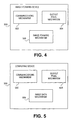
- FIG. 4 is a block diagram of an image-forming device, according to an embodiment of the invention.
- FIG. 5 is a block diagram of a computing device, according to an embodiment of the invention.
- FIG. 1 shows a method 100 according to an embodiment of the invention.
- the method 100 can be implemented by computer-executable instructions, such as those of one or more computer programs, stored on a computer-readable medium.
- the computer-readable medium may be volatile or non-volatile memory, a magnetic, optical, and/or solid state memory, and so on.
- the method 100 is preferably performed in accordance with a halftoning approach, such as an error diffusion technique.
- the method 100 determines whether an output pixel for a color component of an image pixel should be output (102).
- the manner by which the method 100 determines whether to output an output pixel-for a color component of the image pixel is not limited by embodiments of the invention, and a specific approach for such determination is described in a later section of the detailed description.
- the image pixel is preferably one of a number of image pixels of image data.
- the image data has or already has been converted to the same color space as that of the output device, such as an image-forming device like a laser or an inkjet printer, which outputs the output pixels.
- the color space may be the cyan-magenta-yellow-black (CMYK) color space, as may be utilized in color inkjet printers.
- the method 100 also preferably starts at a first pixel of the image data, and at a darkest color component of the image pixel.
- each image pixel of the image data there is an intensity value for each color component of the color space of the image data.
- a given image pixel may have intensity values between 0 and 255 for each of the cyan, magenta, yellow, and black color components.
- An output pixel may be output for each color component of the image pixel.
- An output pixel is binary, having on and off states. That an output pixel has been output means that the on state of the output pixel has been output, such as corresponding to the ejection of ink or other fluid by the image-forming device, or such as the exposure of a region on a photoconductor corresponding to the output pixel by a laser in the image-forming device.
- That an output pixe I has not been output means that the output pixel has the off state, such as corresponding to no ink or other fluid being ejected by the image-forming device, or no exposure of the region on the photoconductor corresponding to the output pixel.
- the output pixel for the color component of the image pixel is output (106).
- ink or other fluid may be ejected by the image-forming device where the device is an inkjet printer or other fluid -ejection device. This is known as firing the output pixel, since the inkjet pen corresponding to the color component of the image pixel is fired to output the output pixel.
- the location corresponding to the output pixel on a photoconductor of a laser pixel may be turned on or off such that toner is later applied to media at this location. That is, a region corresponding to the output pixel is set on the photoconductor or other laser-printing mechanism.
- the method 100 spaces out the output of output pixels for other color components of the image pixel (108), should such output pixels be determined to be output. This means that no output pixel, for no other color component of the image pixel, will likely be output for the image pixel. That is, rather than outputting other output pixels for other color components of the image pixel, such output pixels will instead be spaced out farther away from the output pixel that has been output in 106. Such spacing out of the output pixels allows for a better distribution of the output pixels, leading to a more eye-pleasing pattern of output pixels being output. A specific approach to spacing out of output pixels is described in a later section of the detailed description.
- the method 100 advances to the next image pixel (116), and repeats 102, 104, and so on. If there are no further image pixels in the image data (114), then the method 100 is finished (118). However, if the method 100 has determined to not output an output pixel for the color component in 102 (104), and there are further color components of the image pixel (110), then the method 100 proceeds to advance to the next color component (112), and repeats 102, 104, and so on. For example, where the method 100 starts with the darkest color component, it then advances to the next-darkest color component, and so on, until the lightest color component is reached.
- this ordering is black, cyan, magenta, and yellow, or black, magenta, cyan, and yellow, from darkest to lightest. If there are no further color components of the image pixel (110), however, then the method proceeds to 114, as has been described.
- the determination in 102 as to whether to output an output pixel for a color component of an image pixel is performed in correlation with determining whether to output output pixels for one or more other color components of the image pixel.
- one such approach is known as plane-dependent halftoning, because the decision as to whether an output pixel for one color component, or plane, is output is made in conjunction with the decision as to whether an output pixel for another, adjacent color component, or plane, is output.
- the two color components that are commonly correlated in this respect are cyan and magenta.
- FIG. 2 shows a simple representative scenario 200 of the performance of the method 100 of FIG. 1, according to an embodiment of the invention.
- image data may include hundreds, thousands, millions, or more image pixels, corresponding to a like number of pixel locations.
- the pixel location 202 is blacked out, indicating that an output pixel for the black color component of an image pixel has been output. This means that output pixels for the other color components of the image pixel are likely to be spaced out relative to the black output pixel at the pixel location 202.
- the pixel location 208 is shaded, indicating that an output pixel for the magenta color component of an image pixel has been output.
- the method 100 has output the magenta output pixel at the pixel location 208, instead of at the pixel location 202, 204, or 206, so that the magnet output pixel is spaced out relative to the black output pixel at the pixel location 202.
- FIG. 3 shows a more detailed embodiment of the method 100, which is consistent with the method 100 of the embodiment of FIG. 1.
- Like-numbered parts of the method 100 in the embodiments of FIGs. 1 and 3 achieve the same functionality in both the embodiments of FIGs. 1 and 3.
- the manner by which such functionality is described as being achieved in the embodiment of FIG. 3 does not limit the general functionality of such like-numbered parts that has already been described relative to the embodiment of FIG. 1.
- the method 100 of the embodiment of FIG. 3 is described in relation to image data having a cyan-magenta-yellow-black (CMYK) color space.
- CMYK cyan-magenta-yellow-black
- Each image pixel of the image data has an intensity value for each color component of the color space.
- the method 100 of the embodiment of FIG. 3 is further described in relation to there being 256 possible intensity values, from zero through 255, for each color component of each image pixel of the image data. That is, the CMYK color space is an eight-bit color space, since 2 ⁇ 8 equals 256.
- the method 100 starts with the first image pixel, such as the upper lefthand corner pixel, of the image data as the current image pixel (302).
- the method 100 initially resets the accumulated errors for all the color components (304). There is a n accumulated error for each color component.
- the accumulated error for a color component is the running total of the differences between the intensity values for the color component of the image pixels and the values for the output pixels for the color component of the image pixels. Because the output pixels are binary, it is said that the lower value that an output pixel can have is zero, and the upper value that an output pixel can have is 255, or two to the power of the size of the color space, minus one.
- the intensity value for the cyan color component of a given image pixel is 186, and an output pixel was output for the cyan color component of this pixel, such that the output pixel has a value of 255, the difference (186 - 255) would be added to the accumulated error.
- the method 100 further starts with the darkest color component as the current color component (306).
- the darkest color component of the CMYK color space is black, followed by cyan, magenta, and yellow, from darkestto lightest.
- An error adjustment factor is then reset (307), such that the error adjustment factor is reset each time there is a new current image pixel, prior to the color components of the current image pixel being examined.
- the error adjustment factor is utilized to determine whether an output pixel should be output for a color component of an image pixel. More particularly, the error adjustment factor is utilized to space out the output of output pixels for color components of image pixels.
- Spacing out the output of output pixels in the embodiment of FIG. 3 is based on the insight that when the accumulated error for a given color component is relatively small, an output pixel for the color component has likely recently been output. Furthermore, when the accumulated error for a given color component is relatively large, an output pixel for the color component is likely to be output very soon.
- These insights are employed in conjunction with the error adjustment factor to effectively manage the output of output pixels so that they are better distributed, and result in a more eye-pleasing pattern. That is, the insights are implemented within the error adjustment factor to effectively hasten or delay the output of output pixels as appropriate so thatthey are better distributed.
- the intensity value of the current color component of the current image pixel is added to the accumulated error for the current color component (308), and the method 100 determines whether an output pixel should be output for the current color component of the current image pixel (104). More specifically, the method 100 determines in 104 whether the accumulated error for the current color component minus the error adjustment factor is greater than a threshold. The threshold may be 128, or half the value of two to the power of the size of the color space. If the method 100 determines that an output pixel should be output for the current color component of the current image pixel, then the output pixel for the current color component of the current image pixel is output (106).
- the absolute difference between the accumulated error for the current color component and an update value is then added to the error adjustment factor to update the error adjustment factor (312).
- the update value in one embodiment of the invention is half of the threshold utilized in 104, or one-fourth of the value of two to the power of the size of the color space. That is, the update value may be 64 in one embodiment of the invention.
- the error adjustment factor is thus utilized to bias whether an output pixel is output for the current color component of the current image pixel in 104. As the error adjustment factor increases in 312, it is less likely that output pixels will be output for subsequent color components of the current image pixel, unless the accumulated errors for those color components are relatively large.
- the value for the output pixel for the current color component of the current pixel is then subtracted from the accumulated error for the current color component (314). This distributes the error for the current color component, for determining whether an output pixel should be output for the current color component of subsequent image pixels in 104.
- the value of the output pixel when the output pixel was actually output is 255, whereas the value of the output pixel when no output pixel was actually output is zero. This is because the output pixel is binary, having a maximum value, or 255, when the output pixel is output, and having a minimum value, or zero, when it is not output.
- the method 100 determines whether the accumulated error for the current color component is greater than a maximum allowed error value, which can be defined in a number of different manners.
- the maximum allowed error value is the maximum allowed intensity of a color component of an image pixel, or two to the power of the size of the color space.
- the maximum allowed error value is two times the threshold that is utilized in 104 of the method 100 of the embodiment of FIG. 3.
- the maximum allowed error value can be, for instance, 256. If the method 100 determines that the accumulated error for the current color component is greater than the maximum allowed error value (310), then the output pixel for the current color component of the current image pixel is output (106).
- the error adjustment factor is updated (312), and the accumulated error for the current color component is updated (314), as has been described. Furthermore, where no output pixel has been output for the current color component of the current image pixel, resulting from the method 100 proceeding from 104 to 310, then the error adjustment factor (312) and the accumulated error (314) are still updated.
- the method 100 next determines whether there are any further color components of the current image pixel (110). If there are, the current color component is advanced to the next darkest color component (112), such as from black to cyan, from cyan to magenta, or from magenta to yellow. The method 100 then repeats 308 as has been described.
- the method 100 determines whether there are any further image pixels of the image data (114). If there are, then the method 100 advances the current image pixel to the next image pixel (116), and repeats 306 as has been described. If there are not, then the method 100 is finished (118).
- FIGs. 4 and 5 show block diagrams of different devices, according to varying embodiments of the invention, which can perform the method 100 of FIGs. 1 and 3.
- an image-forming device 500 is depicted, according to an embodiment of the invention.
- the image-forming device 500 may be an inkjet printer, a laser printer, or another type of image-forming device.
- the image-forming device 500 includes a communications mechanism 502, an output pixel mechanism 504, and an image-forming mechanism 506.
- the devic e 500 can include other mechanisms in addition to or in lieu of the mechanisms depicted in FIG. 4.
- the image-forming device 500 forms images on media, such as paper and other types of media.
- the communications mechanism 502 receives image data that has a number of image pixels, from a communicatively coupled source device, such as a computing device like a computer, a digital camera, a personal digital assistant (PDA) device, or another type of computing device.
- the communications mechanism 502 may include wired and/or wireless communications adapters, such as serial ports, Universal Serial Bus (USB) ports, parallel ports, Ethernet adapters, 802.11 b wireless network adapters, Bluetooth wireless adapters, and so on.
- the output pixel mechanism 504 performs the method 100 of the embodiments of FIGs. 1 and/or 3 that have been described. That is, the output pixel mechanism 504 determines whether, for each color component of each image pixel, an output pixel should be output.
- the output pixel mechanism 504 may include computer-executable instructions organized as computer programs, subroutines, modules, objects, and so on.
- the output pixel mechanism 504 outputs the output pixels by utilizing the image-forming mechanism 506, which actually forms images on media.
- the image-forming mechanism 506 may be an inkjet-printing mechanism.
- the image-forming mechanism 506 may be a laser-printing mechanism.
- the image-forming mechanism 506 may be another type of image-forming mechanism as well.
- FIG. 5 shows a computing device 600, according to an embodiment of the invention.
- the phrase computing device is used generally, such that the device may be a computer, like a desktop or a laptop computer, a personal digital assistant (PDA) device, a digital camera, or another type of computing device.
- the computing device 600 includes a communications mechanism 602, the output pixel mechanism 604, and an image data mechanism 606.
- the device 600 can include other mechanism in addition to or in lieu of the mechanisms depicted in FIG. 5.
- the communications mechanism 602 is for communicating with an image-forming device, like the device 500 of FIG. 4, such that the device 600 is communicatively coupled with the device 500.
- the mechanism 602 may thus include wired and/or wireless communications adapters, as have been described.
- the communications mechanism 602 more specifically sends the output pixels for the color components of the image pixels to the image-forming device 500 for image formation corresponding thereto on media.
- the output pixel mechanism 604 thus performs the method 100 of the embodiments of FIGs. 1 and/or 3 that have been described. Once the output pixel mechanism 604 determines whether, for each color component of each image pixel, an output pixel should be output, such output pixels are sent by the communications mechanism 602 to the image-forming device. Thus, the output pixel mechanism 604 outputs the output pixels by utilizing the image-forming device to which the device 600 is communicatively coupled.
- the output pixel mechanism 604 can include computer-executable instructions organized as computer programs, subroutines, modules, objects and so on.
- the image data mechanism 606 receives the image data that includes the image pixels for which the output pixel mechanism 604 determines whether output pixels should be output.
- the image data mechanism 606 may receive the image data from an internal or external source.
- the image data mechanism 606 may internally receive the image data from an application program running on the computing device 600, or externally from a peripheral device communicatively coupled to the computing device 600.
- the image data mechanism 606 may include computer-executable instructions organized as computer programs, subroutines, modules, objects, and so on, and, like the communications mechanism 602, the mechanism 606 may include wired and/or wireless communications adapters.
- Embodiments of the invention have been described thus far are particularly related to binary halftoning, in which an output pixel for a given color component of an image pixel is either on or off. That is, the output pixel may have one of two values.
- the output pixel may have one of two values.
- other embodiments of the invention can be utilized in conjunction with multi-level halftoning, in which an output pixel for a given color component of an image pixel may have one of a number of different values.
- a given output pixel may correspond to zero, one, or two drops of ink, such that there are three different values that the output pixel can have.
- the color component of an image pixel is effectively d ivided into a number of levels. For instance, there may be three levels, eight-bit values between zero and X, eight-bit values greater than X and less than Y, and eight-bit values greater than or equal to Y. Whereas in the binary halftoning embodiment that has been described an output pixel has a value of 255, such that ink is actually output, above a given threshold, and has a value of zero, such that ink is not output, below a given threshold, in this multi-level halftoning embodiment, there are two thresholds.
- one drop of ink may be output for an output pixel having a value between X and Y, whereas two or more drops of ink may be output for an output pixel having a value at or above Y.
- values above 128 receive base level one and scaled contone values of 255 ? value ? 128 / 128.
- a lookup table may alternatively be used to obtain the base level and scaled contone value. The end result is then that binary halftoning can be used on the scaled contone value, and the result of the binary halftoning added to the base level.
Landscapes
- Engineering & Computer Science (AREA)
- Multimedia (AREA)
- Signal Processing (AREA)
- Facsimile Image Signal Circuits (AREA)
- Color, Gradation (AREA)
- Color Image Communication Systems (AREA)
- Image Processing (AREA)
- Editing Of Facsimile Originals (AREA)
Applications Claiming Priority (2)
| Application Number | Priority Date | Filing Date | Title |
|---|---|---|---|
| US304492 | 1981-09-22 | ||
| US10/304,492 US7502138B2 (en) | 2002-11-25 | 2002-11-25 | Spacing out output of pixels for other color components upon output of pixel for color component of an image pixel |
Publications (2)
| Publication Number | Publication Date |
|---|---|
| EP1422927A2 true EP1422927A2 (de) | 2004-05-26 |
| EP1422927A3 EP1422927A3 (de) | 2007-01-17 |
Family
ID=32229956
Family Applications (1)
| Application Number | Title | Priority Date | Filing Date |
|---|---|---|---|
| EP03013054A Withdrawn EP1422927A3 (de) | 2002-11-25 | 2003-06-10 | Ausgabe von Bildelementen für Farbbildkomponenten |
Country Status (3)
| Country | Link |
|---|---|
| US (1) | US7502138B2 (de) |
| EP (1) | EP1422927A3 (de) |
| JP (1) | JP2004180305A (de) |
Families Citing this family (4)
| Publication number | Priority date | Publication date | Assignee | Title |
|---|---|---|---|---|
| US8169659B2 (en) * | 2004-02-17 | 2012-05-01 | Xerox Corporation | Systems and methods for reducing a trade-off between image quality and marking speed |
| US7626729B2 (en) * | 2005-03-02 | 2009-12-01 | Xerox Corporation | Halftoning with color error diffusion of one separation based on color error diffusion of a previous separation |
| US8159720B2 (en) * | 2005-04-08 | 2012-04-17 | Xerox Corporation | Color error diffusion |
| US7440140B2 (en) * | 2005-04-29 | 2008-10-21 | Hewlett-Packard Development Company, L.P. | Sequential color error diffusion with forward and backward exchange of information between color planes |
Family Cites Families (9)
| Publication number | Priority date | Publication date | Assignee | Title |
|---|---|---|---|---|
| US5235435A (en) * | 1989-11-08 | 1993-08-10 | Adobe Systems Incorporated | Method of producing halftone images |
| US5210602A (en) | 1991-02-25 | 1993-05-11 | International Business Machines Corporation | Coupled-color error diffusion |
| US5535019A (en) | 1994-09-15 | 1996-07-09 | Xerox Corporation | Error diffusion halftoning with homogeneous response in high/low intensity image regions |
| JP3034446B2 (ja) | 1995-03-14 | 2000-04-17 | 株式会社東芝 | カラー画像記録装置 |
| CA2169902A1 (en) | 1995-03-16 | 1996-09-17 | Allan Chiwan Cheung | Combined color halftoning |
| JP3322522B2 (ja) * | 1995-05-16 | 2002-09-09 | ブラザー工業株式会社 | カラー画像処理装置 |
| US5739917A (en) | 1996-07-12 | 1998-04-14 | Seiko Epson Corporation | Error-diffusion-type half-toning employing adaptive thresholding for enhanced smoothness |
| US5949965A (en) | 1997-06-23 | 1999-09-07 | Hewlett-Packard Company | Correlating cyan and magenta planes for error diffusion halftoning |
| US6867884B1 (en) | 2000-07-07 | 2005-03-15 | Kodak Polychrome Graphics, Llc | Halftone dot placement for multi-color images |
-
2002
- 2002-11-25 US US10/304,492 patent/US7502138B2/en not_active Expired - Lifetime
-
2003
- 2003-06-10 EP EP03013054A patent/EP1422927A3/de not_active Withdrawn
- 2003-11-21 JP JP2003392731A patent/JP2004180305A/ja not_active Withdrawn
Also Published As
| Publication number | Publication date |
|---|---|
| EP1422927A3 (de) | 2007-01-17 |
| JP2004180305A (ja) | 2004-06-24 |
| US7502138B2 (en) | 2009-03-10 |
| US20040100646A1 (en) | 2004-05-27 |
Similar Documents
| Publication | Publication Date | Title |
|---|---|---|
| US7440140B2 (en) | Sequential color error diffusion with forward and backward exchange of information between color planes | |
| EP0887998B1 (de) | Korrelation von Cyan und Magentaebenen für die Fehlerdiffusionhalbtonrasterung | |
| US20220284247A1 (en) | Secondary color uniformity compensation mechanism | |
| US8437045B2 (en) | Bitmapped based trapping methods, apparatus and system by modifying non-black halftone pixel bitmap plane using estimated continuous tone value | |
| US20220286578A1 (en) | Secondary color uniformity compensation mechanism | |
| US8094954B2 (en) | Image processing apparatus, image processing method and image processing program that performs a level conversion on multilevel input image data | |
| JPH11314383A (ja) | プリント・ドライバ製造方法及びカラー印刷システム | |
| US8054506B2 (en) | Image forming apparatus and image quality enhancement method thereof | |
| US8045809B2 (en) | Image forming apparatus | |
| US8368961B2 (en) | Image processing device and method for creating binary image data using a single set of dither matrices | |
| US7502138B2 (en) | Spacing out output of pixels for other color components upon output of pixel for color component of an image pixel | |
| JP5121592B2 (ja) | 画像形成装置および画像処理方法 | |
| US6914700B2 (en) | Method for reducing migrating residual error in error diffusion halftoning | |
| US7457015B2 (en) | Color printing | |
| US7230740B2 (en) | Substantial preclusion of output of pixels for other color components upon output of pixel for image pixel color component | |
| CN100579786C (zh) | 彩色打印方法 | |
| US20060203280A1 (en) | Image printing apparatus and image printing method | |
| US11679599B2 (en) | Image processing apparatus and control method thereof generating quantized based on multinary color data and a threshold matrix | |
| KR20100046532A (ko) | 화상형성장치, 화상형성시스템 및 그 인쇄방법 | |
| US7040730B2 (en) | Color printing | |
| JP7434502B2 (ja) | 画像処理装置、画像処理方法、プログラム | |
| JP7191665B2 (ja) | 画像処理装置、画像処理方法およびプログラム | |
| JP4748985B2 (ja) | ドットの孤立を低減するハーフトーン画像形成方法および装置 | |
| JP2006035810A (ja) | レーザプリンタ | |
| US20090040540A1 (en) | Image processing apparatus and method of controlling the same |
Legal Events
| Date | Code | Title | Description |
|---|---|---|---|
| PUAI | Public reference made under article 153(3) epc to a published international application that has entered the european phase |
Free format text: ORIGINAL CODE: 0009012 |
|
| AK | Designated contracting states |
Kind code of ref document: A2 Designated state(s): AT BE BG CH CY CZ DE DK EE ES FI FR GB GR HU IE IT LI LU MC NL PT RO SE SI SK TR |
|
| AX | Request for extension of the european patent |
Extension state: AL LT LV MK |
|
| PUAL | Search report despatched |
Free format text: ORIGINAL CODE: 0009013 |
|
| AK | Designated contracting states |
Kind code of ref document: A3 Designated state(s): AT BE BG CH CY CZ DE DK EE ES FI FR GB GR HU IE IT LI LU MC NL PT RO SE SI SK TR |
|
| AX | Request for extension of the european patent |
Extension state: AL LT LV MK |
|
| 17P | Request for examination filed |
Effective date: 20070619 |
|
| AKX | Designation fees paid |
Designated state(s): AT BE BG CH CY CZ DE DK EE ES FI FR GB GR HU IE IT LI LU MC NL PT RO SE SI SK TR |
|
| 17Q | First examination report despatched |
Effective date: 20071105 |
|
| STAA | Information on the status of an ep patent application or granted ep patent |
Free format text: STATUS: THE APPLICATION IS DEEMED TO BE WITHDRAWN |
|
| 18D | Application deemed to be withdrawn |
Effective date: 20080318 |