EP1422772A2 - Akkumulator mit Umwälzvorrichtung zum Homogenisieren des Elektrolyten - Google Patents
Akkumulator mit Umwälzvorrichtung zum Homogenisieren des Elektrolyten Download PDFInfo
- Publication number
- EP1422772A2 EP1422772A2 EP02025982A EP02025982A EP1422772A2 EP 1422772 A2 EP1422772 A2 EP 1422772A2 EP 02025982 A EP02025982 A EP 02025982A EP 02025982 A EP02025982 A EP 02025982A EP 1422772 A2 EP1422772 A2 EP 1422772A2
- Authority
- EP
- European Patent Office
- Prior art keywords
- electrolyte
- accumulator
- circulating
- cell
- circulation
- Prior art date
- Legal status (The legal status is an assumption and is not a legal conclusion. Google has not performed a legal analysis and makes no representation as to the accuracy of the status listed.)
- Granted
Links
Images


Classifications
-
- H—ELECTRICITY
- H01—ELECTRIC ELEMENTS
- H01M—PROCESSES OR MEANS, e.g. BATTERIES, FOR THE DIRECT CONVERSION OF CHEMICAL ENERGY INTO ELECTRICAL ENERGY
- H01M10/00—Secondary cells; Manufacture thereof
- H01M10/42—Methods or arrangements for servicing or maintenance of secondary cells or secondary half-cells
- H01M10/4214—Arrangements for moving electrodes or electrolyte
-
- H—ELECTRICITY
- H01—ELECTRIC ELEMENTS
- H01M—PROCESSES OR MEANS, e.g. BATTERIES, FOR THE DIRECT CONVERSION OF CHEMICAL ENERGY INTO ELECTRICAL ENERGY
- H01M50/00—Constructional details or processes of manufacture of the non-active parts of electrochemical cells other than fuel cells, e.g. hybrid cells
- H01M50/70—Arrangements for stirring or circulating the electrolyte
-
- Y—GENERAL TAGGING OF NEW TECHNOLOGICAL DEVELOPMENTS; GENERAL TAGGING OF CROSS-SECTIONAL TECHNOLOGIES SPANNING OVER SEVERAL SECTIONS OF THE IPC; TECHNICAL SUBJECTS COVERED BY FORMER USPC CROSS-REFERENCE ART COLLECTIONS [XRACs] AND DIGESTS
- Y02—TECHNOLOGIES OR APPLICATIONS FOR MITIGATION OR ADAPTATION AGAINST CLIMATE CHANGE
- Y02E—REDUCTION OF GREENHOUSE GAS [GHG] EMISSIONS, RELATED TO ENERGY GENERATION, TRANSMISSION OR DISTRIBUTION
- Y02E60/00—Enabling technologies; Technologies with a potential or indirect contribution to GHG emissions mitigation
- Y02E60/10—Energy storage using batteries
Definitions
- the present invention relates to an accumulator with an electrolyte having cell and two arranged in the cell, each with at least a pole of electrically connected electrodes, each at least partially with are in contact with the electrolyte.
- the invention further relates to a method for Homogenize a substance concentration of an electrolyte in one Accumulator according to the invention.
- the invention proposes that the accumulator have means for circulating the electrolyte.
- the present invention it is possible for the first time to achieve a largely homogeneous substance concentration in the electrolyte even in a completely closed cell of an accumulator by circulating the electrolyte.
- the present invention can also be used to circulate the electrolyte during normal operation of the battery, so that an improvement in the characteristic properties such as current carrying capacity, voltage stability or the like can be achieved.
- the means for circulation can be formed, for example, by a pump.
- the pump can be coupled to an electric or a hydraulic drive.
- Circulation can advantageously be independent of others Cells of the accumulator can be reached.
- a common means of circulation be provided if, for example, synchronous operation is desired.
- the pump can be integrated into an accumulator or cell wall his.
- it can also be a component that is known Fastener is connected to the cell wall.
- the means for circulating a Displacement pump in particular has a diaphragm pump. So it can Pump can be designed, for example, as a reciprocating piston pump.
- a particularly simple embodiment forms a diaphragm pump, which with known means can be adapted to the chemically corrosive environment. Pumps of this type are already widely used to convey acids.
- the diaphragm pump can consist of a few components, so that a high Reliability is achievable.
- the means for circulating a Has a centrifugal pump can be a closed impeller have, but it can also have an open impeller, for example reduce the number of components.
- open running wheels are particularly suitable, especially if one Charging process hydrogen and oxygen gas is generated.
- the medium for Circulating an electric motor connected to the circulating means having.
- a robust and compact drive can be achieved, whereby additionally the drive can be supplied with energy by the accumulator.
- the motor is preferably a DC motor, in particular a brushless DC motor, which is characterized by low maintenance and distinguishes great reliability.
- the engine can also be operated by a electrically operated solenoids are formed, the reciprocating piston for example via a linkage with a membrane of a membrane pump in Active connection is established. By activating and deactivating the Solenoids can thus generate a back and forth movement that corresponding movements of the membrane causes. Rotating parts can thus largely saved.
- the Motor however, also by a pneumatic or a hydraulic motor be educated.
- a control unit is provided, by means of which the means for circulating is controllable. It can advantageously be achieved that energy for the drive can be saved. In addition, by reducing the Operating time of the drive and / or the pump a reduction of the Wear can be achieved.
- a measuring element can also be provided with which the homogeneity of the substance concentration of the electrolyte can be determined is, and the drive needs when falling below a predetermined Limit is activated. This can ensure that the distribution of the Concentration of the electrolyte does not have a predetermined degree of deviation below.
- control unit with a housing of the Accumulator is integrally formed.
- a separate housing for the Control unit as well as installation and wiring effort can be saved become.
- the housing of the battery can be one for Receiving the control unit provided opening, which is also a Forms housing for the control unit.
- the means for circulating with the housing of the accumulator is integrally formed. Assembly and component effort can be further reduced.
- existing components are used to form the means for circulation be, for example, by one side wall of an accumulator cell at the same time can be used as a membrane of a membrane pump.
- the invention provides a method for homogenizing a Concentration of matter of an electrolyte in a cell of an inventive Accumulator proposed, the electrolyte being circulated. Will be beneficial achieved by the circulation that areas of the electrolyte with different Concentration of substances are mixed, thereby reducing Differences in a local concentration of the electrolyte can be achieved can.
- the electrolyte be used of an intake duct is sucked in from a predeterminable position.
- the means for circulation at any point on the accumulator be arranged, for example outside the cell in the battery cover, whereby via the intake duct, for example an intake hose, the Electrolyte is sucked in at a predeterminable position.
- Such a solution can also be retrofitted to an existing accumulator be provided.
- the electrolyte be connected to another channel a definable position is promoted.
- this configuration can be achieved be that, for example, in the upper area of the battery cell arranged means for circulation in the area of the electrolyte level with electrolyte low substance concentration and via the further channel to a definable position, in this case preferably in the lower region of the Battery cell promotes.
- a suction duct is provided and the further channel can be achieved that the means for circulation can be arranged anywhere in the accumulator. By ordering the Channels can be ensured a desired circulation effect.
- the means for Circulation is controlled as required.
- a Measuring device can be provided with the deviations of the substance concentration of the electrolyte is determined at different local locations and at If a predetermined threshold is exceeded, the means for circulation is activated. So a high degree of homogeneity of the substance concentration of the Electrolytes can be achieved with low energy consumption.
- the means for circulation depending on a current load on the accumulator is controlled. So can for example, the means to circulate only while loading the Accumulator must be switched on, but it can also be used for one High current discharge can be switched on, for example the To improve the high-current characteristic of the battery.
- the means for Circulation depending on an operating state with the accumulator connectable electrical system is controlled. For example, at one connected to an electrical system of a motor vehicle Accumulator in the starting process of the engine of the motor vehicle means be turned on for circulation.
- the means for circulation depending on predeterminable time intervals is controlled. It can advantageously be achieved that without additional measuring means a further reduction in the energy expenditure for the upheaval is achieved.
- FIG. 1 is a sectional view through a cell 12 of an accumulator 14 shown, which is filled to a level 32 with an electrolyte 10.
- the Cell 12 In the Cell 12 are arranged electrodes 18, each with not shown Poles of the battery 14 electrically connected and with the electrolyte 10 are in contact.
- a housing 24 of the accumulator 14 has one Cell opening 38, which is closed by a plug 36.
- Another opening 40 is a protruding into the accumulator cell 21
- Sleeve 42 arranged.
- the sleeve 42 extends from Area of the opening 40 up to the electrolyte 10.
- the in the electrolyte 10 protruding end of the sleeve 42 is closed. Centric to the axis of the sleeve 42, the bottom 52 has an opening 50 through which a drive shaft 54 for a centrifugal pump 16 protrudes.
- the drive shaft 54 is at its upper end a motor shaft of the DC motor 20, not shown.
- the DC motor 20 is brushless here.
- another O-ring 56 is provided in the The area of the passage of the drive shaft 54 through the base 52 . In addition to a function, this serves as Seal at the same time as a bearing for the drive shaft 54.
- a pump housing 58 is attached on the motor 20 opposite end of the sleeve 42.
- the pump housing 58 has a nozzle 62 in the region of the outlet opening 28 on which a hose 30 is attached.
- a hose 30 accelerated electrolyte 10 promoted in the lower region of the cell 12.
- electrolyte 10 becomes a homogenization the substance concentration within the electrolyte 10 is reached.
- the one that occurs when charging a lead-sulfuric acid battery Density gradient of the electrolyte 10 depending on the height can be on this Way be reduced. So the electrodes 18 are permanently in one largely homogeneous electrolytes 10, resulting in a high electrochemical Effectiveness can be achieved.
- FIG. 2 shows a modification of the pump 16 to that shown in FIG. 1 Design.
- a sleeve 64 also forms that for the Centrifugal pump required pump housing.
- Functions and features are based on the description of the embodiment in FIG. 1 directed.
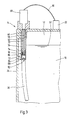
- Fig. 3 shows a further embodiment of the present invention, wherein the Drive for the means for circulation is formed by a solenoid 68 which, as in the previous embodiments, at an opening 40 of the Accumulator housing 24 is attached.
- a sleeve 76 is arranged, which is a central Has bore 78 in which a lifting rod 70 is arranged axially displaceable.
- the opposite end of the sleeve 76 protrudes into the electrolyte 10
- the end of the sleeve 76 protruding into the electrolyte 10 has an opening 74 on the side to exit the electrolyte 10.
- the Displacement pump 72 which is designed here as a reciprocating pump, one Pump chamber 84 in which a piston 86 connected to the lifting rod 70 is axially displaceable.
- a valve 88 provided for the entry of electrolytes 10 into the space 84.
- the piston 86 has a further valve 90, via which the electrolyte located in the space 84 is added a downward movement of the piston 86 from the reciprocating pump 72 is promoted.
- the electrolyte 10 is sucked in.
- Promotion of the electrolyte 10 can be achieved when the level of Electrolyte 10 is very low, in particular below the outlet opening 74.
- a control unit 22 is also arranged on the accumulator housing 24
- the lifting magnet 68 is supplied with energy via connecting lines 80. So a conveying effect can be achieved by executing several lifting cycles, whereby the electrolyte 10 is circulated. It can be beneficial Gradient formation in the vertical substance concentration can be reduced.
- the solenoid 68 is controlled when a Charging process of the accumulator 14 via a not shown Communication link is transmitted.
- the control unit 22 also instructs time-controlled program, which circulates the electrolyte 10th provides for five minutes every hour.
Landscapes
- Chemical & Material Sciences (AREA)
- Chemical Kinetics & Catalysis (AREA)
- Electrochemistry (AREA)
- General Chemical & Material Sciences (AREA)
- Engineering & Computer Science (AREA)
- Manufacturing & Machinery (AREA)
- Filling, Topping-Up Batteries (AREA)
- Fuel Cell (AREA)
- Supply Devices, Intensifiers, Converters, And Telemotors (AREA)
- Electrolytic Production Of Non-Metals, Compounds, Apparatuses Therefor (AREA)
- Hybrid Cells (AREA)
Abstract
Die Mittel zur Umwälzung können bedarfsgerecht gesteuert sein, beispielweise in vorgebbaren Zeitintervallen oder in Abhängigkeit vom Betriebszustand des Akkumulators.
Description
- Fig. 1
- einen Schnitt durch einen Ausschnitt einer Zelle eines Akkumulators mit einer Kreiselpumpe,
- Fig. 2
- eine schematische Darstellung der am Gehäuse befestigten Kreiselpumpe in Fig. 1 und
- Fig. 3
- eine schematische Darstellung einer weiteren erfindungsgemäßen Ausgestaltung mit einer Verdrängerpumpe.
- 10
- Elektrolyt
- 12
- Zelle
- 14
- Akkumulator
- 16
- Pumpe
- 18
- Elektrode
- 20
- Gleichstrommotor
- 22
- Steuereinheit
- 24
- Gehäuse
- 26
- Ansaugöffnung
- 28
- Austrittsöffnung
- 30
- Schlauch
- 32
- Pegel
- 36
- Verschlußstopfen
- 38
- Zellenöffnung
- 40
- Öffnung
- 42
- Hülse
- 44
- Kragen
- 46
- O-Ring
- 48
- Ringnut
- 50
- Öffnung
- 52
- Boden
- 54
- Antriebswelle
- 56
- O-Ring
- 58
- Pumpengehäuse
- 60
- Flügel
- 62
- Stutzen
- 64
- Hülse
- 66
- Öffnung
- 68
- Hubmagnet
- 70
- Hubgestänge
- 72
- Verdrängerpumpe
- 74
- Austrittsöffnung
- 76
- Hülse
- 78
- Bohrung
- 80
- Verbindungsleitung
- 82
- Eintrittsöffnung
- 84
- Raum
- 86
- Kolben
- 88
- Ventil
- 90
- Ventil
Claims (18)
- Akkumulator (14) mit einer einen Elektrolyten (10) aufweisenden Zelle (12) sowie zwei in der Zelle (12) angeordneten, mit jeweils wenigstens einem Pol elektrisch verbundenen Elektroden (18), die jeweils zumindest teilweise mit dem Elektrolyten (10) in Kontakt stehen, dadurch gekennzeichnet, daß der Akkumulator (14) Mittel (16) zum Umwälzen des Elektrolyten (10) aufweist.
- Akkumulator nach Anspruch 1, dadurch gekennzeichnet, daß das Mittel zum Umwälzen in der Zelle (12) angeordnet ist.
- Akkumulator nach Anspruch 1 oder 2, dadurch gekennzeichnet, daß das Mittel zum Umwälzen (16) eine Verdrängerpumpe, insbesondere eine Membranpumpe, aufweist.
- Akkumulator nach Anspruch 1 oder 2, daß das Mittel (16) zum Umwälzen eine Kreiselpumpe aufweist.
- Akkumulator nach einem der Ansprüche 1 bis 4, dadurch gekennzeichnet, daß das Mittel (16) zum Umwälzen einen mit dem Mittel (16) zum Umwälzen verbundenen, elektrischen Motor (20) aufweist.
- Akkumulator nach einem der Ansprüche 1 bis 5, dadurch gekennzeichnet, daß eine Steuereinheit (22) vorgesehen ist, mittels der das Mittel (16) zum Umwälzen steuerbar ist.
- Akkumulator nach Anspruch 6, dadurch gekennzeichnet, daß die Steuereinheit mit einem Gehäuse (24) des Akkumulators einstückig ausgebildet ist.
- Akkumulator nach einem der Ansprüche 1 bis 7, dadurch gekennzeichnet, daß das Mittel (16) zum Umwälzen mit dem Gehäuse (24) des Akkumulators (14) einstückig ausgebildet ist.
- Verfahren zum Homogenisieren einer Stoffkonzentration eines Elektrolyten (10) in einer Zelle (12) eines Akkumulators (14) nach einem der Ansprüche 1 bis 8, dadurch gekennzeichnet, daß der Elektrolyt (10) umgewälzt wird.
- Verfahren nach Anspruch 9, dadurch gekennzeichnet, daß der Elektrolyt (10) über eine in den Elektrolyten (10) ragende Ansaugöffnung (26) angesaugt, durch Mittel (16) zum Umwälzen beschleunigt wird und über eine Austrittsöffnung (28) des Mittels (16) zum Umwälzen in den Elektrolyten (10) austritt.
- Verfahren nach Anspruch 9 oder 10, dadurch gekennzeichnet, daß der Elektrolyt (10) mittels eines Ansaugkanals von einer vorgebbaren Position angesaugt wird.
- Verfahren nach einem der Ansprüche 9 bis 11, dadurch gekennzeichnet, daß der Elektrolyt (10) mittels einem weiteren Kanal (30) an eine vorgebbare Position gefördert wird.
- Verfahren nach einem der Ansprüche 9 bis 12, dadurch gekennzeichnet, daß das Mittel (16) zum Umwälzen bedarfsgerecht gesteuert wird.
- Verfahren nach Anspruch 13, dadurch gekennzeichnet, daß das Mittel (16) zum Umwälzen in Abhängigkeit von einer Strombeanspruchung des Akkumulators (14) gesteuert wird.
- Verfahren nach Anspruch 13 oder 14, dadurch gekennzeichnet, daß das Mittel (16) zum Umwälzen in Abhängigkeit von einem Betriebszustand einer mit dem Akkumulator (14) verbindbaren elektrischen Anlage gesteuert wird.
- Verfahren nach einem der Ansprüche 13 bis 15, dadurch gekennzeichnet, daß das Mittel (16) zum Umwälzen in Abhängigkeit von vorgebbaren Zeitintervallen gesteuert wird.
- Verfahren nach einem der Ansprüche 9 bis 16, dadurch gekennzeichnet, daß als Elektrolyt (10) Schwefelsäure verwendet wird.
- Verfahren nach einem der Ansprüche 9 bis 17, dadurch gekennzeichnet, daß als Elektroden (18) Bleielektroden verwendet werden.
Priority Applications (5)
| Application Number | Priority Date | Filing Date | Title |
|---|---|---|---|
| EP02025982A EP1422772B1 (de) | 2002-11-21 | 2002-11-21 | Akkumulator mit Umwälzvorrichtung zum Homogenisieren des Elektrolyten |
| ES02025982T ES2278863T3 (es) | 2002-11-21 | 2002-11-21 | Acumulador con dispositivo de recirculacion para la homogeneizacion del electrolito. |
| AT02025982T ATE349077T1 (de) | 2002-11-21 | 2002-11-21 | Akkumulator mit umwälzvorrichtung zum homogenisieren des elektrolyten |
| DE50209024T DE50209024D1 (de) | 2002-11-21 | 2002-11-21 | Akkumulator mit Umwälzvorrichtung zum Homogenisieren des Elektrolyten |
| PT02025982T PT1422772E (pt) | 2002-11-21 | 2002-11-21 | Acumulador com dispositivo de circulação do electrólito para homogeneização do mesmo |
Applications Claiming Priority (1)
| Application Number | Priority Date | Filing Date | Title |
|---|---|---|---|
| EP02025982A EP1422772B1 (de) | 2002-11-21 | 2002-11-21 | Akkumulator mit Umwälzvorrichtung zum Homogenisieren des Elektrolyten |
Publications (3)
| Publication Number | Publication Date |
|---|---|
| EP1422772A2 true EP1422772A2 (de) | 2004-05-26 |
| EP1422772A3 EP1422772A3 (de) | 2004-06-16 |
| EP1422772B1 EP1422772B1 (de) | 2006-12-20 |
Family
ID=32187179
Family Applications (1)
| Application Number | Title | Priority Date | Filing Date |
|---|---|---|---|
| EP02025982A Expired - Lifetime EP1422772B1 (de) | 2002-11-21 | 2002-11-21 | Akkumulator mit Umwälzvorrichtung zum Homogenisieren des Elektrolyten |
Country Status (5)
| Country | Link |
|---|---|
| EP (1) | EP1422772B1 (de) |
| AT (1) | ATE349077T1 (de) |
| DE (1) | DE50209024D1 (de) |
| ES (1) | ES2278863T3 (de) |
| PT (1) | PT1422772E (de) |
Cited By (2)
| Publication number | Priority date | Publication date | Assignee | Title |
|---|---|---|---|---|
| DE102006038046A1 (de) * | 2006-08-16 | 2008-02-21 | Iq Power Licensing Ag | Verfahren zur Erhöhung der Startsicherheit der Brennkraftmaschine eines Fahrzeugs |
| DE102016222998A1 (de) * | 2016-11-22 | 2018-05-24 | Bayerische Motoren Werke Aktiengesellschaft | Sekundäre elektrochemische Zelle |
Family Cites Families (8)
| Publication number | Priority date | Publication date | Assignee | Title |
|---|---|---|---|---|
| JPS57141865A (en) * | 1981-02-25 | 1982-09-02 | Yuasa Battery Co Ltd | Storage battery |
| JPS5875764A (ja) * | 1981-10-30 | 1983-05-07 | Yuasa Battery Co Ltd | 蓄電池 |
| JPS59127369A (ja) * | 1983-01-10 | 1984-07-23 | Matsushita Electric Ind Co Ltd | 電池 |
| US4565748A (en) * | 1985-01-31 | 1986-01-21 | Dahl Ernest A | Magnetically operated electrolyte circulation system |
| FR2600214A1 (fr) * | 1986-06-16 | 1987-12-18 | Serggie | Batterie electrique reversible avec electrolyte mis en circulation |
| JPH0294255A (ja) * | 1988-09-29 | 1990-04-05 | Aisin Seiki Co Ltd | 車輌用二次電池 |
| US5665484A (en) * | 1995-09-18 | 1997-09-09 | Inductran Corporation | Electrolyte conditioning system |
| JP4227678B2 (ja) * | 1997-12-22 | 2009-02-18 | Necエンジニアリング株式会社 | 蓄電池用電解液の攪拌装置 |
-
2002
- 2002-11-21 ES ES02025982T patent/ES2278863T3/es not_active Expired - Lifetime
- 2002-11-21 EP EP02025982A patent/EP1422772B1/de not_active Expired - Lifetime
- 2002-11-21 AT AT02025982T patent/ATE349077T1/de active
- 2002-11-21 PT PT02025982T patent/PT1422772E/pt unknown
- 2002-11-21 DE DE50209024T patent/DE50209024D1/de not_active Expired - Lifetime
Cited By (2)
| Publication number | Priority date | Publication date | Assignee | Title |
|---|---|---|---|---|
| DE102006038046A1 (de) * | 2006-08-16 | 2008-02-21 | Iq Power Licensing Ag | Verfahren zur Erhöhung der Startsicherheit der Brennkraftmaschine eines Fahrzeugs |
| DE102016222998A1 (de) * | 2016-11-22 | 2018-05-24 | Bayerische Motoren Werke Aktiengesellschaft | Sekundäre elektrochemische Zelle |
Also Published As
| Publication number | Publication date |
|---|---|
| ES2278863T3 (es) | 2007-08-16 |
| DE50209024D1 (de) | 2007-02-01 |
| PT1422772E (pt) | 2007-02-28 |
| EP1422772B1 (de) | 2006-12-20 |
| ATE349077T1 (de) | 2007-01-15 |
| EP1422772A3 (de) | 2004-06-16 |
Similar Documents
| Publication | Publication Date | Title |
|---|---|---|
| DE3435821C2 (de) | Lager für eine Pumpe | |
| DE112004000729B4 (de) | Künstliche Herzpumpe | |
| DE1811100A1 (de) | Vorrichtung zum Schmieren eines Lagers zur Verwendung in einer gekapselten Motorpumpe oder einem gekapselten Motorruehrwerk | |
| DE4300368C2 (de) | Elektrische Kraftstoffpumpe | |
| DE102022112501A1 (de) | Kältemittelkompressor mit einer Ölstandssensoranordnung | |
| DE20221499U1 (de) | Elektroantrieb | |
| DE69416263T2 (de) | Lager für die Rotorwelle einer Kreiselpumpe mit einem permanent magnetischen elektrischen Motor | |
| DE19962705A1 (de) | Tragestruktur für eine Schleifbürste eines Motors sowie Pumpe mit einem mit einer solchen Tragestruktur versehenen Motor | |
| DE102014106932A1 (de) | Pumpe | |
| DE102018121253A1 (de) | Pumpenaufbau mit benutzer zugänglichem nassem bereich | |
| DE112014004249T5 (de) | Kraftstoffpumpe | |
| WO2019072892A1 (de) | Kraftstoffpumpe und kraftstofffördereinheit | |
| WO2019072887A1 (de) | Kraftstoffpumpe und kraftstofffördereinheit | |
| EP1936200A2 (de) | Schmiermittelgedichtete Drehschiebervakuumpumpe | |
| EP0629780A1 (de) | Tauchmotorpumpe | |
| EP1422772A2 (de) | Akkumulator mit Umwälzvorrichtung zum Homogenisieren des Elektrolyten | |
| DE102007041899A1 (de) | Bürsteneinrichtung und Kraftstoffpumpe | |
| EP1130741A2 (de) | Pumpe mit saugseitigem Antriebsrotor | |
| DE102017218285A1 (de) | Kraftstoffpumpe und Kraftstofffördereinheit | |
| DE212021000213U1 (de) | Wasserpumpe und Reinigungsgerät | |
| DE102008062054B4 (de) | Anordnung mit Vakuumpumpe und Verfahren zum Betrieb einer Vakuumpumpe | |
| DE2557891A1 (de) | Geschlossener elektromagnetischer kompressor | |
| DE29823424U1 (de) | Kreiselpumpe mit Gleitringdichtung | |
| DE102015211741A1 (de) | Pumpe mit Anlaufscheibe | |
| DE102022206140A1 (de) | Fluidpumpe |
Legal Events
| Date | Code | Title | Description |
|---|---|---|---|
| PUAI | Public reference made under article 153(3) epc to a published international application that has entered the european phase |
Free format text: ORIGINAL CODE: 0009012 |
|
| PUAL | Search report despatched |
Free format text: ORIGINAL CODE: 0009013 |
|
| AK | Designated contracting states |
Kind code of ref document: A2 Designated state(s): AT BE BG CH CY CZ DE DK EE ES FI FR GB GR IE IT LI LU MC NL PT SE SK TR |
|
| AX | Request for extension of the european patent |
Extension state: AL LT LV MK RO SI |
|
| AK | Designated contracting states |
Kind code of ref document: A3 Designated state(s): AT BE BG CH CY CZ DE DK EE ES FI FR GB GR IE IT LI LU MC NL PT SE SK TR |
|
| AX | Request for extension of the european patent |
Extension state: AL LT LV MK RO SI |
|
| 17P | Request for examination filed |
Effective date: 20041202 |
|
| AKX | Designation fees paid |
Designated state(s): AT BE BG CH CY CZ DE DK EE ES FI FR GB GR IE IT LI LU MC NL PT SE SK TR |
|
| 17Q | First examination report despatched |
Effective date: 20050131 |
|
| GRAP | Despatch of communication of intention to grant a patent |
Free format text: ORIGINAL CODE: EPIDOSNIGR1 |
|
| GRAS | Grant fee paid |
Free format text: ORIGINAL CODE: EPIDOSNIGR3 |
|
| GRAA | (expected) grant |
Free format text: ORIGINAL CODE: 0009210 |
|
| AK | Designated contracting states |
Kind code of ref document: B1 Designated state(s): AT BE BG CH CY CZ DE DK EE ES FI FR GB GR IE IT LI LU MC NL PT SE SK TR |
|
| PG25 | Lapsed in a contracting state [announced via postgrant information from national office to epo] |
Ref country code: CZ Free format text: LAPSE BECAUSE OF FAILURE TO SUBMIT A TRANSLATION OF THE DESCRIPTION OR TO PAY THE FEE WITHIN THE PRESCRIBED TIME-LIMIT Effective date: 20061220 Ref country code: DK Free format text: LAPSE BECAUSE OF FAILURE TO SUBMIT A TRANSLATION OF THE DESCRIPTION OR TO PAY THE FEE WITHIN THE PRESCRIBED TIME-LIMIT Effective date: 20061220 Ref country code: IE Free format text: LAPSE BECAUSE OF FAILURE TO SUBMIT A TRANSLATION OF THE DESCRIPTION OR TO PAY THE FEE WITHIN THE PRESCRIBED TIME-LIMIT Effective date: 20061220 Ref country code: FI Free format text: LAPSE BECAUSE OF FAILURE TO SUBMIT A TRANSLATION OF THE DESCRIPTION OR TO PAY THE FEE WITHIN THE PRESCRIBED TIME-LIMIT Effective date: 20061220 Ref country code: NL Free format text: LAPSE BECAUSE OF FAILURE TO SUBMIT A TRANSLATION OF THE DESCRIPTION OR TO PAY THE FEE WITHIN THE PRESCRIBED TIME-LIMIT Effective date: 20061220 Ref country code: SK Free format text: LAPSE BECAUSE OF FAILURE TO SUBMIT A TRANSLATION OF THE DESCRIPTION OR TO PAY THE FEE WITHIN THE PRESCRIBED TIME-LIMIT Effective date: 20061220 |
|
| REG | Reference to a national code |
Ref country code: GB Ref legal event code: FG4D Free format text: NOT ENGLISH |
|
| REG | Reference to a national code |
Ref country code: CH Ref legal event code: EP |
|
| REF | Corresponds to: |
Ref document number: 50209024 Country of ref document: DE Date of ref document: 20070201 Kind code of ref document: P |
|
| REG | Reference to a national code |
Ref country code: IE Ref legal event code: FG4D Free format text: LANGUAGE OF EP DOCUMENT: GERMAN |
|
| REG | Reference to a national code |
Ref country code: CH Ref legal event code: NV Representative=s name: E. BLUM & CO. AG PATENT- UND MARKENANWAELTE VSP |
|
| GBT | Gb: translation of ep patent filed (gb section 77(6)(a)/1977) |
Effective date: 20070131 |
|
| REG | Reference to a national code |
Ref country code: PT Ref legal event code: SC4A Free format text: AVAILABILITY OF NATIONAL TRANSLATION Effective date: 20070202 |
|
| PG25 | Lapsed in a contracting state [announced via postgrant information from national office to epo] |
Ref country code: BG Free format text: LAPSE BECAUSE OF FAILURE TO SUBMIT A TRANSLATION OF THE DESCRIPTION OR TO PAY THE FEE WITHIN THE PRESCRIBED TIME-LIMIT Effective date: 20070320 Ref country code: SE Free format text: LAPSE BECAUSE OF FAILURE TO SUBMIT A TRANSLATION OF THE DESCRIPTION OR TO PAY THE FEE WITHIN THE PRESCRIBED TIME-LIMIT Effective date: 20070320 |
|
| NLV1 | Nl: lapsed or annulled due to failure to fulfill the requirements of art. 29p and 29m of the patents act | ||
| ET | Fr: translation filed | ||
| REG | Reference to a national code |
Ref country code: ES Ref legal event code: FG2A Ref document number: 2278863 Country of ref document: ES Kind code of ref document: T3 |
|
| PLBE | No opposition filed within time limit |
Free format text: ORIGINAL CODE: 0009261 |
|
| STAA | Information on the status of an ep patent application or granted ep patent |
Free format text: STATUS: NO OPPOSITION FILED WITHIN TIME LIMIT |
|
| 26N | No opposition filed |
Effective date: 20070921 |
|
| PG25 | Lapsed in a contracting state [announced via postgrant information from national office to epo] |
Ref country code: GR Free format text: LAPSE BECAUSE OF FAILURE TO SUBMIT A TRANSLATION OF THE DESCRIPTION OR TO PAY THE FEE WITHIN THE PRESCRIBED TIME-LIMIT Effective date: 20070321 |
|
| BERE | Be: lapsed |
Owner name: HOPPECKE BATTERIEN G.M.B.H. & CO. KG. Effective date: 20071130 |
|
| PG25 | Lapsed in a contracting state [announced via postgrant information from national office to epo] |
Ref country code: MC Free format text: LAPSE BECAUSE OF NON-PAYMENT OF DUE FEES Effective date: 20071130 |
|
| PG25 | Lapsed in a contracting state [announced via postgrant information from national office to epo] |
Ref country code: BE Free format text: LAPSE BECAUSE OF NON-PAYMENT OF DUE FEES Effective date: 20071130 |
|
| PG25 | Lapsed in a contracting state [announced via postgrant information from national office to epo] |
Ref country code: EE Free format text: LAPSE BECAUSE OF FAILURE TO SUBMIT A TRANSLATION OF THE DESCRIPTION OR TO PAY THE FEE WITHIN THE PRESCRIBED TIME-LIMIT Effective date: 20061220 |
|
| PG25 | Lapsed in a contracting state [announced via postgrant information from national office to epo] |
Ref country code: CY Free format text: LAPSE BECAUSE OF FAILURE TO SUBMIT A TRANSLATION OF THE DESCRIPTION OR TO PAY THE FEE WITHIN THE PRESCRIBED TIME-LIMIT Effective date: 20061220 Ref country code: LU Free format text: LAPSE BECAUSE OF NON-PAYMENT OF DUE FEES Effective date: 20071121 |
|
| PG25 | Lapsed in a contracting state [announced via postgrant information from national office to epo] |
Ref country code: TR Free format text: LAPSE BECAUSE OF FAILURE TO SUBMIT A TRANSLATION OF THE DESCRIPTION OR TO PAY THE FEE WITHIN THE PRESCRIBED TIME-LIMIT Effective date: 20061220 |
|
| PGFP | Annual fee paid to national office [announced via postgrant information from national office to epo] |
Ref country code: AT Payment date: 20101112 Year of fee payment: 9 |
|
| PGFP | Annual fee paid to national office [announced via postgrant information from national office to epo] |
Ref country code: DE Payment date: 20101122 Year of fee payment: 9 |
|
| PGFP | Annual fee paid to national office [announced via postgrant information from national office to epo] |
Ref country code: IT Payment date: 20101124 Year of fee payment: 9 Ref country code: GB Payment date: 20101118 Year of fee payment: 9 |
|
| PGFP | Annual fee paid to national office [announced via postgrant information from national office to epo] |
Ref country code: ES Payment date: 20111125 Year of fee payment: 10 Ref country code: CH Payment date: 20111123 Year of fee payment: 10 Ref country code: PT Payment date: 20111118 Year of fee payment: 10 Ref country code: FR Payment date: 20111130 Year of fee payment: 10 |
|
| REG | Reference to a national code |
Ref country code: PT Ref legal event code: MM4A Free format text: LAPSE DUE TO NON-PAYMENT OF FEES Effective date: 20130521 |
|
| REG | Reference to a national code |
Ref country code: CH Ref legal event code: PL |
|
| REG | Reference to a national code |
Ref country code: AT Ref legal event code: MM01 Ref document number: 349077 Country of ref document: AT Kind code of ref document: T Effective date: 20121121 |
|
| GBPC | Gb: european patent ceased through non-payment of renewal fee |
Effective date: 20121121 |
|
| PG25 | Lapsed in a contracting state [announced via postgrant information from national office to epo] |
Ref country code: CH Free format text: LAPSE BECAUSE OF NON-PAYMENT OF DUE FEES Effective date: 20121130 Ref country code: AT Free format text: LAPSE BECAUSE OF NON-PAYMENT OF DUE FEES Effective date: 20121121 Ref country code: LI Free format text: LAPSE BECAUSE OF NON-PAYMENT OF DUE FEES Effective date: 20121130 |
|
| REG | Reference to a national code |
Ref country code: FR Ref legal event code: ST Effective date: 20130731 |
|
| PG25 | Lapsed in a contracting state [announced via postgrant information from national office to epo] |
Ref country code: PT Free format text: LAPSE BECAUSE OF NON-PAYMENT OF DUE FEES Effective date: 20130521 Ref country code: IT Free format text: LAPSE BECAUSE OF NON-PAYMENT OF DUE FEES Effective date: 20121121 |
|
| REG | Reference to a national code |
Ref country code: DE Ref legal event code: R119 Ref document number: 50209024 Country of ref document: DE Effective date: 20130601 |
|
| PG25 | Lapsed in a contracting state [announced via postgrant information from national office to epo] |
Ref country code: DE Free format text: LAPSE BECAUSE OF NON-PAYMENT OF DUE FEES Effective date: 20130601 |
|
| PG25 | Lapsed in a contracting state [announced via postgrant information from national office to epo] |
Ref country code: FR Free format text: LAPSE BECAUSE OF NON-PAYMENT OF DUE FEES Effective date: 20121130 Ref country code: GB Free format text: LAPSE BECAUSE OF NON-PAYMENT OF DUE FEES Effective date: 20121121 |
|
| REG | Reference to a national code |
Ref country code: ES Ref legal event code: FD2A Effective date: 20140305 |
|
| PG25 | Lapsed in a contracting state [announced via postgrant information from national office to epo] |
Ref country code: ES Free format text: LAPSE BECAUSE OF NON-PAYMENT OF DUE FEES Effective date: 20121122 |