EP1422703A2 - Objektivlinse, optisches System und optisches Abtastgerät - Google Patents
Objektivlinse, optisches System und optisches Abtastgerät Download PDFInfo
- Publication number
- EP1422703A2 EP1422703A2 EP03257226A EP03257226A EP1422703A2 EP 1422703 A2 EP1422703 A2 EP 1422703A2 EP 03257226 A EP03257226 A EP 03257226A EP 03257226 A EP03257226 A EP 03257226A EP 1422703 A2 EP1422703 A2 EP 1422703A2
- Authority
- EP
- European Patent Office
- Prior art keywords
- objective lens
- ring
- optical
- shaped
- optical system
- Prior art date
- Legal status (The legal status is an assumption and is not a legal conclusion. Google has not performed a legal analysis and makes no representation as to the accuracy of the status listed.)
- Withdrawn
Links
Images


Classifications
-
- G—PHYSICS
- G02—OPTICS
- G02B—OPTICAL ELEMENTS, SYSTEMS OR APPARATUS
- G02B13/00—Optical objectives specially designed for the purposes specified below
-
- G—PHYSICS
- G11—INFORMATION STORAGE
- G11B—INFORMATION STORAGE BASED ON RELATIVE MOVEMENT BETWEEN RECORD CARRIER AND TRANSDUCER
- G11B7/00—Recording or reproducing by optical means, e.g. recording using a thermal beam of optical radiation by modifying optical properties or the physical structure, reproducing using an optical beam at lower power by sensing optical properties; Record carriers therefor
- G11B7/12—Heads, e.g. forming of the optical beam spot or modulation of the optical beam
- G11B7/135—Means for guiding the beam from the source to the record carrier or from the record carrier to the detector
- G11B7/1353—Diffractive elements, e.g. holograms or gratings
-
- G—PHYSICS
- G02—OPTICS
- G02B—OPTICAL ELEMENTS, SYSTEMS OR APPARATUS
- G02B27/00—Optical systems or apparatus not provided for by any of the groups G02B1/00 - G02B26/00, G02B30/00
- G02B27/0025—Optical systems or apparatus not provided for by any of the groups G02B1/00 - G02B26/00, G02B30/00 for optical correction, e.g. distorsion, aberration
- G02B27/0037—Optical systems or apparatus not provided for by any of the groups G02B1/00 - G02B26/00, G02B30/00 for optical correction, e.g. distorsion, aberration with diffracting elements
-
- G—PHYSICS
- G02—OPTICS
- G02B—OPTICAL ELEMENTS, SYSTEMS OR APPARATUS
- G02B27/00—Optical systems or apparatus not provided for by any of the groups G02B1/00 - G02B26/00, G02B30/00
- G02B27/42—Diffraction optics, i.e. systems including a diffractive element being designed for providing a diffractive effect
- G02B27/4233—Diffraction optics, i.e. systems including a diffractive element being designed for providing a diffractive effect having a diffractive element [DOE] contributing to a non-imaging application
- G02B27/4238—Diffraction optics, i.e. systems including a diffractive element being designed for providing a diffractive effect having a diffractive element [DOE] contributing to a non-imaging application in optical recording or readout devices
-
- G—PHYSICS
- G02—OPTICS
- G02B—OPTICAL ELEMENTS, SYSTEMS OR APPARATUS
- G02B27/00—Optical systems or apparatus not provided for by any of the groups G02B1/00 - G02B26/00, G02B30/00
- G02B27/42—Diffraction optics, i.e. systems including a diffractive element being designed for providing a diffractive effect
- G02B27/4272—Diffraction optics, i.e. systems including a diffractive element being designed for providing a diffractive effect having plural diffractive elements positioned sequentially along the optical path
-
- G—PHYSICS
- G11—INFORMATION STORAGE
- G11B—INFORMATION STORAGE BASED ON RELATIVE MOVEMENT BETWEEN RECORD CARRIER AND TRANSDUCER
- G11B7/00—Recording or reproducing by optical means, e.g. recording using a thermal beam of optical radiation by modifying optical properties or the physical structure, reproducing using an optical beam at lower power by sensing optical properties; Record carriers therefor
- G11B7/12—Heads, e.g. forming of the optical beam spot or modulation of the optical beam
- G11B7/135—Means for guiding the beam from the source to the record carrier or from the record carrier to the detector
- G11B7/1372—Lenses
- G11B7/1374—Objective lenses
-
- G—PHYSICS
- G11—INFORMATION STORAGE
- G11B—INFORMATION STORAGE BASED ON RELATIVE MOVEMENT BETWEEN RECORD CARRIER AND TRANSDUCER
- G11B7/00—Recording or reproducing by optical means, e.g. recording using a thermal beam of optical radiation by modifying optical properties or the physical structure, reproducing using an optical beam at lower power by sensing optical properties; Record carriers therefor
- G11B7/12—Heads, e.g. forming of the optical beam spot or modulation of the optical beam
- G11B7/135—Means for guiding the beam from the source to the record carrier or from the record carrier to the detector
- G11B7/1372—Lenses
- G11B7/1378—Separate aberration correction lenses; Cylindrical lenses to generate astigmatism; Beam expanders
-
- G—PHYSICS
- G11—INFORMATION STORAGE
- G11B—INFORMATION STORAGE BASED ON RELATIVE MOVEMENT BETWEEN RECORD CARRIER AND TRANSDUCER
- G11B7/00—Recording or reproducing by optical means, e.g. recording using a thermal beam of optical radiation by modifying optical properties or the physical structure, reproducing using an optical beam at lower power by sensing optical properties; Record carriers therefor
- G11B7/12—Heads, e.g. forming of the optical beam spot or modulation of the optical beam
- G11B7/135—Means for guiding the beam from the source to the record carrier or from the record carrier to the detector
- G11B7/1392—Means for controlling the beam wavefront, e.g. for correction of aberration
- G11B7/13922—Means for controlling the beam wavefront, e.g. for correction of aberration passive
Definitions
- the present invention relates to an optical system for an optical pickup device, an optical pickup device and an objective lens, and in particular, to an optical system for an optical pickup device, an optical pickup device and an objective lens which can achieve high density recording or reproducing for information.
- CD compact disc
- DVD digital versatile disc
- an optical disc has been used for storage of digital data such as accumulation of music information and image information or storage of computer data. Further, with the recent advent of an information-oriented society, there are actual circumstances wherein large capacities of the optical discs are strongly demanded.
- an improvement of recording capacity (recording density) per a unit area can be realized by making a spot diameter of a light-converged spot obtained from the optical system for an optical pickup device, in the optical disc. Since this spot diameter is proportional to ⁇ /NA (in which, ⁇ represents a wavelength of a light source and NA represents a numerical aperture on the image side of the objective lens) as is known widely, a short wavelength of the light source used in the optical pickup device and a high numerical aperture of the objective lens arranged to face the optical disc are effective for making a spot diameter.
- An optical pickup device described in the aforementioned Patent Document 1 is one wherein longitudinal chromatic aberration of an objective lens is corrected by a diffractive element arranged in a parallel light flux between a violet semiconductor laser light source and an objective lens
- an optical system for an optical pickup device described in the aforementioned Patent Document 2 is one wherein a diffractive structure is formed on an optical surface of a collimator lens for converting a divergent light flux emitted from a violet semiconductor laser light source into a parallel light flux to lead it to an objective lens, and thereby, longitudinal aberration of the objective lens is corrected by the actions of the diffractive structure
- an optical pickup device described in the Patent Document 3 is one wherein a diffractive structure is formed on an optical surface of an expander lens arranged in a parallel light flux between a violet semiconductor laser light source and an objective lens, and thereby, longitudinal chromatic aberration of the objective lens is corrected by the actions of the diffractive structure.
- a wavelength difference of about ⁇ 10 nm caused by manufacture errors exists between semiconductor laser individuals each being used as a light source in an optical pickup device.
- initial adjustment for a position of a collimator lens and that for a position of a semiconductor laser are necessary for eliminating spherical aberration that is caused by changes of magnification of the objective lens, which increases manufacturing cost for the optical pickup device.
- the problem stated above is in a tendency that it is actualized by a single lens representing an objective lens having a high numerical aperture which is generally one way to realize cost reduction and downsizing of an optical pickup device.
- a single lens spherical aberration increases in proportion to the fourth power of the numerical aperture. It is therefore necessary to correct spherical chromatic aberration remaining on the objective lens itself in addition to spherical aberration changes caused by magnification changes of the objective lens, in adjustment of a collimator lens position and in the initial adjustment of a semiconductor laser position.
- the material having a high refractive index is generally of low divergence, and therefore, an amount of longitudinal chromatic aberration to be corrected by a chromatic aberration correcting element is in a tendency to grow greater. Therefore, for correcting longitudinal chromatic aberration of an objective lens that is made of the material with high refractive index, it is necessary that changes in degrees of divergence of the light flux advancing toward the objective lens from a chromatic aberration correcting element caused by changes of wavelength of semiconductor laser are established to be large, which results in that changes in magnification of the objective lens becomes large when using the semiconductor laser whose wavelength is deviated from a design wavelength of the optical system of the optical pickup device. Therefore, an occurrence of spherical aberration caused by changes in magnification of the objective lens is increased, which increases an amount of initial adjustment for a collimator lens position and an amount of initial adjustment for a semiconductor laser position.
- spherical aberration caused by the changes of magnification of the objective lens
- a chromatic aberration correcting element so that spherical aberration (hereinafter, spherical aberration in the case where a wavelength of incident light is changed is called spherical chromatic aberration) may be changed when a wavelength of the semiconductor laser is changed.
- the invention has been achieved in view of the problems mentioned above, and its object is to provide an optical system for an optical pickup device housed in the optical pickup device employing a violet light source with a short wavelength, wherein occurrence of spherical aberration is sufficiently less when a wavelength of incident light is changed, and occurrence of coma is sufficiently less even when an objective lens is eccentric in the direction perpendicular to the optical axis from the chromatic aberration correcting element, when a wavelength of incident light is changed. Its further object is to provide an objective lens that can be applied to an optical system for the optical pickup device. Providing of an optical pickup device in which an optical system for the optical pickup device and an objective lens are housed is also an object of the invention.
- An optical element for an optical pickup device described in Item 1 is one equipped with a chromatic aberration correcting element and an objective lens that converges a light flux coming from the chromatic aberration correcting element, wherein the chromatic aberration correcting element is composed of plural ring-shaped zones divided by microscopic steps, and has, on at least one optical surface thereof, a ring-shaped zonal structure that is displaced in the direction of an optical axis on each boundary so that an optical path length for a light flux that has passed through an outer ring-shaped zone may be longer than that for a light flux that has passed through an inner ring-shaped zone, the objective lens is composed of plural ring-shaped zones divided by microscopic steps, and has, on at least one optical surface thereof, a ring-shaped zonal structure wherein adjoining ring-shaped zones generate a prescribed optical path difference for prescribed incident light, and the following expression is satisfied when ⁇ SAR represents an amount of changes of spherical aberration of a marginal light beam in the case when light with
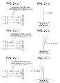
- Fig. 1 (a) is a sectional view of optical system OS for an optical pickup device relating to the invention
- Fig. 1 (b) is an enlarged view of an optical surface of an chromatic aberration correcting element
- Fig. 1 (c) is an enlarged view of an optical surface of an objective lens.
- the optical system OS for an optical pickup device relating to the invention is composed of chromatic aberration correcting element CA arranged in a parallel light flux emitted from an unillustrated violet semiconductor laser light source and collimated by an unillustrated collimator lens and of objective lens OBJ that converges a light flux having passed through the chromatic aberration correcting element CA on information recording surface DR through protective layer DP of optical disk OD, as shown in Fig. 1.
- a surface of incidence for a light flux on the chromatic aberration correcting element CA is divided by plural ring-shaped zones as shown in the enlarged view (Fig. 1 (B)), and an optical path length of a light flux passing through an outer ring-shaped zone among adjoining ring-shaped zones is displaced in the direction of an optical axis at its boundary so that the optical path length of the light flux passing through the outer ring-shaped zone may be longer than that of a light flux passing through the inner ring-shaped zone.
- This diffractive structure is a diffractive structure wherein diffracting actions make adjoining ring-shaped zones to generate diffracted light of a prescribed order for prescribed passing incident light, and the chromatic aberration correcting element CA has wavelength keeping quality of paraxial power that changes in the direction wherein the paraxial power grows greater when a wavelength of incident light becomes longer.
- a light flux emerging from the chromatic aberration correcting element CA becomes a convergent light flux
- a wavelength of incident light becomes shorter by ⁇ from design wavelength ⁇ 0
- the longitudinal chromatic aberration of the objective lens can be corrected by the chromatic aberration correcting element CA because a light flux emerging from the chromatic aberration correcting element CA becomes a divergent light flux (see Fig. 2 (a) that is a sectional view of an optical system for an optical pickup device and Fig. 2 (d) that is its aberration diagram).
- a degree of divergence of the light flux advancing toward an objective lens is changed by changes of a wavelength of a semiconductor laser as stated above, there is generated spherical aberration because a magnification of the objective lens is changed.
- a violet semiconductor laser with a wavelength that is longer by ⁇ than design wavelength ⁇ 0 of the optical system of an optical pickup device is used as shown in Fig. 2 (b) representing a sectional view of the optical system of an optical pickup device
- a light flux emerging from the chromatic aberration correcting element CA becomes a convergent light flux. Therefore, the magnification of the objective lens is changed to grow greater, and thereby, spherical aberration of the objective lens is changed to become over (see Fig. 2 (e)).
- a violet semiconductor laser with a wavelength that is shorter by ⁇ than design wavelength ⁇ 0 of the optical system of an optical pickup device is used as shown in Fig. 2 (c) representing a sectional view of the optical system of an optical pickup device
- a light flux emerging from the chromatic aberration correcting element CA becomes a divergent light flux. Therefore, the magnification of the objective lens is changed to become smaller, and thereby, spherical aberration of the objective lens is changed to become under (see Fig. 2 (f)).
- a ring-shaped zonal structure that is composed of plural ring-shaped zones divided by microscopic steps, as described in Item 1 and is formed so that adjoining ring-shaped zones generate a prescribed optical path difference for prescribed incident light,and there is provided a wavelength-dependence of spherical aberration wherein the aforesaid expression (1) is satisfied when ⁇ SAR represents an amount of changes of spherical aberration of a marginal light beam in the case when light with a wavelength that is longer by 10 nm than the design wavelength enter for spherical aberration of marginal light beam in the case when light with the design wavelength enters a refracting lens that has the same design wavelength, material, focal length, numerical aperture on the image side, magnification, lens thickness and back focus and does not have the aforementioned ring-shaped structure, and when ⁇ SAD represents an amount of changes of spher
- design wavelength used in the present specification means a wavelength wherein aberration is minimum when rays of light each having a different wavelength are made to enter an optical element under exactly the same conditions of magnification, temperature and a diameter of incident light flux, or a wavelength wherein diffraction efficiency is maximum when the optical element has a diffractive structure.
- Wavelength characteristics of spherical aberration of the above-mentioned refracting lens and wavelength characteristics of spherical aberration of objective lens OBJ on which the aforesaid ring-shaped zone structure is formed are illustrated to be a spherical aberration diagram shown in Fig. 3.
- an amount of changes of spherical aberration for marginal light beam in the case when light with a wavelength that is longer by 10 nm than the design wavelength enters means a width between an upper end of the spherical aberration curve in the occasion where a spherical aberration curve for design wavelength ⁇ 0 nm is moved in parallel so that its lower end may agree positionally with a lower end of a spherical aberration curve for wavelength ⁇ 0 + 10 nm as shown in Fig. 3 and an upper end of a spherical aberration curve for wavelength ⁇ 0 + 10 nm.
- chromatic aberration correcting element CA When chromatic aberration correcting element CA is used to be combined with the objective lens on which spherical aberration remains as shown in Fig. 3 (a), spherical chromatic aberration of the combination system of the objective lens and the chromatic aberration correcting element CA grows greater than spherical chromatic aberration (Fig. 3 (a)) of the objective lens itself.
- a ring-shaped zone structure formed on the objective lens is a diffractive structure in which diffracting actions make adjoining ring-shaped zones to generate diffracted light at prescribed order for prescribed incident light, wherein a light-converged wave front that is formed by refracting actions and diffracting actions emerges from the objective lens.
- the ring-shaped zone structure formed on the objective lens is an optical path difference providing structure that generates a prescribed optical path difference for the prescribed incident light when adjoining ring-shaped zones are formed by moving mutually on their boundary in the direction of an optical axis, wherein light-converged wave front that is formed by refracting actions emerges from the objective lens.
- the ring-shaped zone structure stated above may also be an optical path difference providing structure without being limited to the diffractive structure, and thereby, it is possible to provide an objective lens capable of obtaining the same effect while avoiding a decline of light transmittance caused by diffraction efficiency of the diffractive structure.
- a preferable objective lens as objective lens OBJ includes one wherein a ring-shaped zone structure as a diffractive structure in which adjoining ring-shaped zones generate diffracted light at prescribed order for prescribed incident light through diffracting actions is formed on at least one optical surface, and a light-converged wave front formed by refracting actions and diffracting actions emerges from the objective lens, as illustrated in Item 2, and one wherein a ring-shaped zone structure as an optical path difference providing structure that generates a prescribed optical path difference for prescribed incident light when adjoining ring-shaped zones are formed by moving mutually in the direction of an optical axis in their boundary is formed on at least one optical surface, and a light-converged wave front formed by refracting actions emerges from the objective lens, as illustrated in Item 3.
- the optical system has at least one of first ring-shaped zone RB1 that is formed when an optical path length of the passing light flux moves in the direction of an optical axis in its boundary so that it may be shorter than an optical path length of a light flux passing through a ring-shaped zone adjoining the inside, and has at least one of second ring-shaped zone RB2 that is formed when an optical path length of the passing light flux moves in the direction of an optical axis in its boundary so that it may be longer than an optical path length of a light flux passing through a ring-shaped zone adjoining the inside, and the first ring-shaped zone is formed to be closer than the second ring-shaped zone to the optical axis, thus, it is possible to make the optical system to have wavelength-dependence of spherical aberration that satisfies the aforementioned expression (1).
- the optical system has at least one of first ring-shaped zone that is formed when an optical path length of the passing light flux moves in the direction of an optical axis in its boundary so that it may be shorter than an optical path length of a light flux passing through a ring-shaped zone adjoining the inside, and has at least one of second ring-shaped zone that is formed when an optical path length of the passing light flux moves in the direction of an optical axis in its boundary so that it may be longer than an optical path length of a light flux passing through a ring-shaped zone adjoining the inside, and the first ring-shaped zone is formed to be closer than the second ring-shaped zone to the optical axis.
- the optical system for an optical pickup device described in Item 5 is an optical system for an optical pickup device equipped with a chromatic aberration correcting element and an objective lens that converges a light flux coming from the chromatic aberration correcting element, wherein the chromatic aberration correcting element has, on at least one optical surface thereof, a ring-shaped zone structure that is composed of plural ring-shaped zones divided by microscopic steps and is displaced in the direction of an optical axis at its boundary so that an optical path length of a light flux passing through an outer ring-shaped zone among ring-shaped zones adjoining mutually may be longer than an optical path length of a light flux passing through the inside ring-shaped zone, and the objective lens has, on at least one optical surface thereof, a ring-shaped zone structure that is composed of plural ring-shaped zones divided by microscopic steps and is formed so that adjoining ring-shaped zones may generate diffracted light at prescribed order for the prescribed incident light, and the optical path difference added by the ring-shaped zone structure to the wave
- b 2 , b 4 and b 6 are respectively coefficients of an optical path difference function of second order, fourth order and sixth order, and at least one optical path difference function coefficient including b 4 among b 4 , b 6 , ... has a value that is not zero), as a function of height h mm from the optical axis.
- the ring-shaped zone structure is formed on an optical surface of objective lens OBJ as a diffractive structure in which mutually adjoining ring-shaped zones generate diffracted light at a prescribed order for the prescribed incident light by diffracting actions
- the aforesaid technical conceptions expressed in a different expression are those described in Item 5.
- the optical path difference to be added, by a ring-shaped zone structure formed on an optical surface of the objective lens OBJ, to the wave front transmitted through objective lens OBJ is expressed by the aforementioned expression (2) as a function of height h mm from the optical axis.
- a coefficient of an optical path difference function of fourth order or more in the optical path difference function it is possible to control wavelength-dependence of spherical aberration of the diffractive structure.
- wavelength characteristics of spherical aberration of the objective lens OBJ it is possible to make wavelength characteristics of spherical aberration of the objective lens OBJ to be those shown in Figs. 3 (b) - 3 (d), when a wavelength of the light entering the diffractive structure is changed to be longer.
- the expression (3) stated above means that a function to correct the longitudinal chromatic aberration of the objective lens is hardly owned by the ring-shaped zone structure formed on an optical surface of objective lens OBJ, and is exclusively owned by the chromatic aberration correcting element CA. Due to this, a distance between adjoining ring-shaped zones on the ring-shaped zone structure formed on an optical surface of objective lens OBJ does not become too small, and thereby, it is possible to control a decline of light transmittance caused by shading of the ring-shaped zone structure that is of a microscopic form to be small, and to make manufacture of the ring-shaped zone structure of this kind to be easy.
- paraxial power P D of the ring-shaped zone structure formed on an optical surface of objective lens OBJ it is preferable to make paraxial power P D of the ring-shaped zone structure formed on an optical surface of objective lens OBJ to be zero, and to prohibit the ring-shaped zone structure formed on the objective lens to have the function to correct longitudinal chromatic aberration of the objective lens.
- the optical surface of objective lens OBJ on which a ring-shaped zone structure representing a diffractive structure is formed is divided into central area IN including an optical axis and peripheral area OUT that surrounds the circumference of the central area IN, and the central area IN is formed as a continuous surface having no step, and a ring-shaped zone structure serving as a diffractive structure is formed on the peripheral area OUT.
- the optical system for an optical pickup device described in Item 7 is an optical system for an optical pickup device equipped with a chromatic aberration correcting element and an objective lens that converges a light flux coming from the chromatic aberration correcting element, wherein the chromatic aberration correcting element is composed of a plurality of ring-shaped zones divided by microscopic steps and has, on at least one optical surface thereof, a ring-shaped zone structure that is displaced in the direction of an optical axis at its boundary so that an optical path length of a light flux passing through an outer ring-shaped zone among ring-shaped zones adjoining mutually may be longer than an optical path length of a light flux passing through the inside ring-shaped zone, and the objective lens is composed of plural ring-shaped zones divided by microscopic steps and has, on at least one optical surface thereof, a ring-shaped zone structure that is formed so that adjoining ring-shaped zones may generate diffracted light at prescribed order for the prescribed incident light, and the optical surface of the objective lens on which the ring
- optical path difference function of fourth order or more in the optical path difference function for controlling wavelength-dependence of spherical aberration for the diffractive structure. Therefore, the optical path difference added to the wave front that is transmitted through objective lens OBJ is increased suddenly as a height from the optical axis grows greater. Therefore, when forming, on an optical surface of objective lens OBJ, a diffractive structure that adds the optical path difference of this kind to the transmitted wave front, a plurality of ring-shaped zonal steps are formed on an are (peripheral area OUT) where a height from the optical axis is great.
- wavelength characteristics of spherical aberration of the objective lens OBJ can be made to be those shown in Figs. 3 (b) - 3 (d). Therefore, it is possible to control spherical aberration of the combination system of the objective lens OBJ and the chromatic aberration correcting element CA to be relatively small and to eliminate spherical aberration caused by changes in the degree of divergence of the light flux advancing from the chromatic aberration correcting element CA to the objective lens OBJ which results from changes in a wavelength of the semiconductor laser.
- the optical pickup device described in Item 8 satisfies the following expression. D1/D2 > 0.2
- the optical pickup device described in Item 9 is an optical system for an optical pickup device equipped with a chromatic aberration correcting element and an objective lens that converges a light flux coming from the chromatic aberration correcting element
- the chromatic aberration correcting element is composed of a plurality of ring-shaped zones divided by microscopic steps and has, on at least one optical surface thereof, a ring-shaped zone structure that is displaced in the direction of an optical axis at its boundary so that an optical path length of a light flux passing through an outer ring-shaped zone among ring-shaped zones adjoining mutually may be longer than an optical path length of a light flux passing through the inside ring-shaped zone
- the objective lens is composed of plural ring-shaped zones divided by microscopic steps and has, on at least one optical surface, a ring-shaped zone structure representing an optical path difference providing structure that generates a prescribed optical path difference for a prescribed incident light when adjoining ring-shaped zones are formed to be displaced mutually in the direction of an optical axi
- the ring-shaped zone structure formed on the objective lens has at least one of the first ring-shaped zone that is displaced in the direction of an optical axis in its boundary and formed so that an optical path length of a passing light flux may be shorter than that of the light flux passing through the ring-shaped zone adjoining the inside, and at least one of the second ring-shaped zone that is displaced in the direction of an optical axis in its boundary and formed so that an optical path length of a passing light flux may be longer than that of the light flux passing through the ring-shaped zone adjoining the inside, and the first ring-shaped zone is formed to be closer than the second ring-shaped zone to the optical axis, and the aforesaid expression (5) is satisfied when D3 mm represents a diameter of the ring-shaped zone positioned to be closest to the optical axis and D4 mm represents a diameter of the maximum effective diameter of the optical surface of the objective lens on which the ring-shaped zone structure is formed.
- wavelength characteristics of spherical aberration of the objective lens OBJ can be made to be those shown in Figs. 3 (b) - 3 (d). Therefore, it is possible to control spherical aberration of the combination system of the objective lens OBJ and the chromatic aberration correcting element CA to be relatively small and to eliminate spherical aberration caused by changes in the degree of divergence of the light flux advancing from the chromatic aberration correcting element CA to the objective lens OBJ which results from changes in a wavelength of the semiconductor laser.
- the objective lens is a single lens in the optical system for an optical pickup device described in Item 10, effects of the invention stated above can be made to be more effective.
- the numerical aperture on the image side (which is also called simply a numerical aperture) of the objective lens is made to be 0.7 or more in the optical system for an optical pickup device described in Item 11, technical effects of the invention can be made to be more effective.
- the objective lens even in the case of an optical pickup device employing an objective lens having a numerical aperture that is as high as 0.7 or more, it is preferable to make the objective lens to be a single as in the past.
- spherical chromatic aberration is increased in proportion to the fourth power of the numerical aperture on the single lens, and therefore, spherical aberration remaining on the objective lens is large.
- an amount of longitudinal chromatic aberration to be corrected by a chromatic aberration correcting element turns out to be large, because a material having a high refractive index is generally of low dispersion. Therefore, for correcting longitudinal chromatic aberration of the objective lens that is made of the high refractive index material of this kind, it is necessary to establish a change of a degree of divergence caused by changes in a wavelength of a semiconductor laser to be large for a light flux advancing from a chromatic aberration correcting element to the objective lens.
- objective lens OBJ of optical system OS for an optical pickup device of the invention is of the structure described in Items 1, 5, 7 and 9, it is possible to eliminate spherical aberration caused by changes of the degree of divergence of the light flux advancing from chromatic aberration correcting element CA to objective lens OBJ caused by changes in a wavelength of a semiconductor laser, and to establish spherical aberration remaining on the chromatic aberration correcting element CA to be small, even when the objective lens OBJ is made to be a single lens with a high numerical aperture and even when a design wavelength is 500 nm or less. Therefore, it is possible to control coma caused by driving for tracking of the objective lens to be small, and excellent tracking characteristics are obtained, even when using a violet semiconductor laser whose wavelength is deviated from a design wavelength of the optical system for an optical pickup device by manufacture errors.
- ⁇ WFE1 representing an amount of changes of spherical aberration on the occasion where light with a wavelength that is longer than the design wavelength by 10 nm enters the objective lens OBJ through the chromatic aberration correcting element CA for spherical aberration on the occasion where light with the design wavelength enters the objective lens OBJ through the chromatic aberration correcting element CA satisfies the above expression (7).
- ⁇ WFE2 represents an amount of changes of spherical aberration on the occasion where light with a wavelength that is longer than the design wavelength by 10 nm enters the objective lens OBJ for spherical aberration on the occasion where light with the design wavelength enters the objective lens OBJ.
- the ring-shaped zone structure formed on the chromatic aberration correcting element is a diffractive structure wherein a prescribed optical path difference is generated for a prescribed incident light by ring-shaped zones adjoining mutually through diffracting actions, and the chromatic aberration correcting element makes a wave front that is formed by refracting actions and diffracting actions to emerge.
- the ring-shaped zone structure formed on the chromatic aberration correcting element is an optical path difference providing structure wherein a prescribed optical path difference is generated for a prescribed incident light when adjoining ring-shaped zones are formed to be displaced mutually in the direction of the optical axis in their boundary, and the chromatic aberration correcting element makes a wave front that is formed by refracting actions to emerge.
- chromatic aberration correcting element CA In addition to the chromatic aberration correcting element wherein the ring-shaped zone structure representing the diffractive structure in which a diffracted light at a prescribed order is generated for a prescribed incident light by ring-shaped zones adjoining mutually through diffracting actions, is formed on at least one optical surface, and a wave front formed by refracting actions and diffracting actions emerges, stated above, the one like that in Item 17 wherein the ring-shaped zone structure representing an optical path difference providing structure wherein a prescribed optical path difference is generated for a prescribed incident light when adjoining ring-shaped zones are formed to be displaced mutually in the direction of the optical axis in their boundary is formed on at least one optical surface, and a wave front formed by refracting actions emerges, is preferable, as chromatic aberration correcting element CA. Due to this, it is possible to provide chromatic aberration correcting element CA which can obtain the same effect while preventing a decline of light transmittance by diffraction efficiency of
- the chromatic aberration correcting element CA it is possible to make the chromatic aberration correcting element CA to have wavelength-dependence of paraxial power wherein the chromatic aberration correcting element CA is changed in the direction for the paraxial power to grow greater when a wavelength of incident light is changed to be longer, thus, longitudinal chromatic aberration of the objective lens OBJ can be corrected properly.
- the chromatic aberration correcting element CA has a ring-shaped zone structure on each of two or more optical surfaces thereof. Due to this, an amount of correction of longitudinal chromatic aberration of the objective lens OBJ can be shared by ring-shaped zone structures on two or more optical surfaces, and thereby, a distance between adjoining ring-shaped zones can be extended. As a result, a decline of light transmittance of the chromatic aberration correcting element CA caused by errors of a form of the ring-shaped zone structure is reduced, and longitudinal chromatic aberration of the objective lens OBJ can be corrected properly.
- the chromatic aberration correcting element is a coupling lens that changes an angle of divergence for an incident divergent light flux.
- the chromatic aberration correcting element is an expander that changes a diameter of an incident light flux.
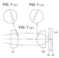
- chromatic aberration correcting element CA capable of being applied to optical system for an optical pickup device OS
- coupling lens CUL that changes an angle of divergence of a divergent light flux emitted from an unillustrated violet semiconductor laser and leads it to objective lens OBJ as shown in Fig. 7, or expander lens EXP that changes a diameter of a parallel light flux collimated by an unillustrated collimator lens and leads it to objective lens OBJ as shown in Fig. 8.
- a diffractive structure of chromatic aberration correcting element CA is formed on a flat surface of optical system for an optical pickup device OS in Fig. 1, it may also be formed on a concave surface or on a convex surface.
- a diameter of a light flux entering the chromatic aberration correcting element CA and a diameter of a light flux emerging from the chromatic aberration correcting element CA can be made equal substantially, when an absolute value of paraxial power of the diffractive structure expressed by the above expression (9) and that of a refraction power as a refracting interface on the concave surface are made equal substantially and their symbols are made opposite each other.
- each ring-shaped zone structure is in a shape of steps.
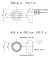
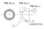
- objective lens OBJ is a single lens in the explanation above, it is also possible to use an objective lens wherein a function of the ring-shaped zone structure in objective lens OBJ and a function as a light-converging lens are separated to be separate lenses (EL1 and EL2) and they are integrated solidly through fitting and adhesion of cementing portions of flanges of respective lenses as shown in Fig. 6, as an objective lens capable of being applied to the optical system for an optical pickup device OS.
- EL1 and EL2 separate lenses
- a radius of curvature of an optical surface it is preferable to establish a radius of curvature of an optical surface to be large by making paraxial power of lens E1 having a function of a ring-shaped zone structure to be almost zero, and to make light-converging lens E2 to have exclusively a light-converging function as an objective lens. Owing to this, a decline of light transmittance caused by shading of the ring-shaped zone structure in a microscopic form can be controlled to be small, and manufacture of the ring-shaped zone structures can be made easy. Further, though lens E1 and lens E2 are integrated solidly through fitting and adhesion of cementing portions of flanges in Fig. 6, lens E1 and lens E2 may also be integrated by a separate member such as a lens barrel.
- the objective lens OBJ is made to be a plastic lens, a ring-shaped zone structure that is a microscopic structure can be formed highly accurately by injection molding, which is preferable.
- the objective lens OBJ is made to be a glass lens, it is preferable to use glass lens whose glass transition point Tg is 400°C or less, and to manufacture through a molding method employing a metal mold. Due to this, molding can be conducted at temperature which is lower than that for ordinary glass lens (Tg is about 530°C) for molding, which is advantageous in terms of reduction of molding time and long life of a metal mold, resulting in realization of low cost of objective lenses.
- Tg glass transition point
- PG 325 trade name
- the optical pickup device described in Item 20 is one having therein a light source and an optical system for the optical pickup device that conducts recording and/or reproducing of information by converging a light flux emitted from the light source on an information recording surface of an optical information recording medium , wherein the optical system for the optical pickup device is provided with a chromatic aberration correcting element and an objective lens that converges a light flux coming from the chromatic aberration correcting element, the chromatic aberration correcting element is composed of plural ring-shaped zones divided by microscopic steps, and has, on at least one optical surface thereof, a ring-shaped zone structure displaced in the direction of an optical axis in its boundary so that an optical path length of a light flux passing through the outer ring-shaped zone among ring-shaped zones adjoining mutually may be longer than an optical path length of a light flux passing through the inner ring-shaped zone, the objective lens is composed of plural ring-shaped zones divided by microscopic steps, and has, on at least one optical surface thereof,
- a ring-shaped zone structure formed on the objective lens is a diffractive structure wherein diffracting actions make ring-shaped zones adjoining mutually to generate diffracted light at prescribed order for a prescribed incident light, and a light-converged wave front formed by refracting actions and diffracting actions emerges from the objective lens.
- Effects of the present invention are the same as those of the invention described in Item 2.
- a ring-shaped zone structure formed on the objective lens is an optical path difference providing structure wherein a prescribed optical path difference is generated for a prescribed incident light by ring-shaped zones adjoining mutually which are formed to be displaced mutually in the direction of an optical axis in their boundary, and a light-converged wave front formed by refracting actions emerges from the objective lens.
- Effects of the present invention are the same as those of the invention described in Item 3.
- the optical system has at least one of first ring-shaped zone that is formed when an optical path length of the passing light flux moves in the direction of an optical axis in its boundary so that it may be shorter than an optical path length of a light flux passing through a ring-shaped zone adjoining the inside, and has at least one of second ring-shaped zone that is formed when an optical path length of the passing light flux moves in the direction of an optical axis in its boundary so that it may be longer than an optical path length of a light flux passing through a ring-shaped zone adjoining the inside, and the first ring-shaped zone stated above is formed to be closer than the aforesaid second ring-shaped zone to the optical axis. Effects of the present invention are the same as those of the invention described in Item 4.
- the optical pickup device described in Item 24 is one having therein a light source and an optical system for the optical pickup device that conducts recording and/or reproducing of information by converging a light flux emitted from the light source on an information recording surface of an optical information recording medium , wherein the optical system for the optical pickup device is provided with a chromatic aberration correcting element and an objective lens that converges a light flux coming from the chromatic aberration correcting element, the chromatic aberration correcting element is composed of plural ring-shaped zones divided by microscopic steps, and has, on at least one optical surface thereof, a ring-shaped zone structure displaced in the direction of an optical axis in its boundary so that an optical path length of a light flux passing through the outer ring-shaped zone among ring-shaped zones adjoining mutually may be longer than an optical path length of a light flux passing through the inner ring-shaped zone, the objective lens is composed of plural ring-shaped zones divided by microscopic steps, and has, on at least one optical surface thereof,
- the optical pickup device described in Item 26 is one having therein a light source and an optical system for the optical pickup device that conducts recording and/or reproducing of information by converging a light flux emitted from the light source on an information recording surface of an optical information recording medium , wherein the optical system for the optical pickup device is provided with a chromatic aberration correcting element and an objective lens that converges a light flux coming from the chromatic aberration correcting element, the chromatic aberration correcting element is composed of plural ring-shaped zones divided by microscopic steps, and has, on at least one optical surface thereof, a ring-shaped zone structure displaced in the direction of an optical axis in its boundary so that an optical path length of a light flux passing through the outer ring-shaped zone among ring-shaped zones adjoining mutually may be longer than an optical path length of a light flux passing through the inner ring-shaped zone, the objective lens is composed of plural ring-shaped zones divided by microscopic steps, and has, on at least one optical surface thereof,
- the optical pickup device described in Item 28 is one having therein a light source and an optical system for the optical pickup device that conducts recording and/or reproducing of information by converging a light flux emitted from the light source on an information recording surface of an optical information recording medium , wherein the optical system for the optical pickup device is provided with a chromatic aberration correcting element and an objective lens that converges a light flux coming from the chromatic aberration correcting element, the chromatic aberration correcting element is composed of plural ring-shaped zones divided by microscopic steps, and has, on at least one optical surface thereof, a ring-shaped zone structure displaced in the direction of an optical axis in its boundary so that an optical path length of a light flux passing through the outer ring-shaped zone among ring-shaped zones adjoining mutually may be longer than an optical path length of a light flux passing through the inner ring-shaped zone, the objective lens is composed of plural ring-shaped zones divided by microscopic steps, and has, on at least one optical surface thereof,
- the objective lens is a single lens. Effects of the present invention are the same as those of the invention described in Item 10.
- the numerical aperture on the image side of the objective lens is made to be 0.7 or more. Effects of the present invention are the same as those of the invention described in Item 11.
- the design wavelength is 500 nm or less. Effects of the present invention are the same as those of the invention described in Item 12.
- ⁇ SAD represents an amount of changes of spherical aberration of a marginal light beam in the case when light with a wavelength that is longer by 10 nm than the design wavelength for spherical aberration of a marginal light beam in the case when light with the design wavelength enters the aforesaid objective lens.
- ⁇ SAD ⁇ 0 Effects of the present invention are the same as those of the invention described in Item 13.
- ⁇ WFE 1 represents an amount of changes of spherical aberration in the case when light with a wavelength that is longer by 10 nm than the design wavelength is made to enter the objective lens through the chromatic aberration correcting element for spherical aberration in the case when light with the design wavelength is made to enter the objective lens through the chromatic aberration correcting element.
- ⁇ 0.03 ⁇ rms Effects of the present invention are the same as those of the invention described in Item 14.
- the ring-shaped zone structure formed on the chromatic aberration correcting element is a diffractive structure wherein diffracting actions make ring-shaped zones adjoining mutually to generate a prescribed optical path difference for a prescribed incident light, and the chromatic aberration correcting element makes a wave front formed by refracting actions and diffracting actions to emerge.
- Effects of the present invention are the same as those of the invention described in Item 15.
- the ring-shaped zone structure formed on the chromatic aberration correcting element is an optical path difference providing structure wherein a prescribed optical path difference is generated for a prescribed incident light when adjoining ring-shaped zones are formed to be displaced in the direction of the optical axis in their boundary, and the chromatic aberration correcting element makes a wave front that is formed by refracting actions to emerge.
- Effects of the present invention are the same as those of the invention described in Item 17.
- the chromatic aberration correcting element is a coupling lens that changes an angle of divergence for an incident divergent light flux. Effects of the present invention are the same as those of the invention described in Item 18.
- the chromatic aberration correcting element is an expander lens that changes a diameter of an incident light flux. Effects of the present invention are the same as those of the invention described in Item 19.
- the chromatic aberration correcting element is arranged to be fixed in the optical path between the light source and the objective lens, and when conducting at least one of recording and reproducing of information for the optical information recording medium, an actuator displaces the objective lens only in the direction perpendicular to the optical axis, and converges a light flux coming from the light source on the prescribed track.
- an actuator displaces the objective lens only in the direction perpendicular to the optical axis, and converges a light flux coming from the light source on the prescribed track.
- the objective lens described in Item 40 is one for an optical pickup device whose numerical aperture on the image side is 0.7 or more, wherein the objective lens is composed of plural ring-shaped zones divided by microscopic steps, and it has, on at least one optical surface, a ring-shaped zone structure that is formed so that adjoining ring-shaped zones may generate diffracted light at prescribed order for a prescribed incident light, and an optical surface of the objective lens on which the ring-shaped zone structure is formed is divided into a central area that includes an optical axis and is a continuous surface having no steps and a peripheral area that surrounds the circumference of the central area and has the steps thereon. Effects of the present invention are the same as those of the invention described in Item 11.
- the objective lens described in Item 41 is one for an optical pickup device whose design wavelength is 500 nm or less, wherein the objective lens is composed of plural ring-shaped zones divided by microscopic steps and has, on at least one optical surface thereof, a ring-shaped zone structure that is formed so that adjoining ring-shaped zones may generate diffracted light at prescribed order for the prescribed incident light, and the optical surface of the objective lens on which the ring-shaped zone structure is formed is divided into a central area that includes an optical axis and is made to be the continuous surface having no step and a peripheral area that surrounds the circumference of the central area and is provided with the step. Effects of the present invention are the same as those of the invention described in Item 12.
- paraxial power P D of the ring-shaped zone structure is zero.
- the objective lens described in Item 46 is one for an optical pickup device whose numerical aperture on the image side is 0.7 or more, wherein the objective lens is composed of plural ring-shaped zones divided by microscopic steps and has, on at least one optical surface, a ring-shaped zone structure representing an optical path difference providing structure that generates a prescribed optical path difference for a prescribed incident light when adjoining ring-shaped zones are formed to be displaced mutually in the direction of an optical axis in its boundary, and light-converging wave front formed by refracting actions emerges from the objective lens, and further, the ring-shaped zone structure formed on the objective lens has at least one of the first ring-shaped zone that is displaced in the direction of an optical axis in its boundary and formed so that an optical path length of a passing light flux may be shorter than that of the light flux passing through the ring-shaped zone adjoining the inside, and at least one of the second ring-shaped zone that is displaced in the direction of an optical axis in its boundary and formed so that an optical path
- the objective lens described in Item 47 is one for an optical pickup device whose working wavelength is 500 nm r less, wherein the objective lens is composed of plural ring-shaped zones divided by microscopic steps and has, on at least one optical surface, a ring-shaped zone structure representing an optical path difference providing structure that generates a prescribed optical path difference for a prescribed incident light when adjoining ring-shaped zones are formed to be displaced mutually in the direction of an optical axis in its boundary, and light-converging wave front formed by refracting actions emerges from the objective lens, and further, the ring-shaped zone structure formed on the objective lens has at least one of the first ring-shaped zone that is displaced in the direction of an optical axis in its boundary and formed so that an optical path length of a passing light flux may be shorter than that of the light flux passing through the ring-shaped zone adjoining the inside, and at least one of the second ring-shaped zone that is displaced in the direction of an optical axis in its boundary and formed so that an optical path length
- ⁇ SAR represents an amount of changes of spherical aberration of a marginal light beam in the case when light with a wavelength that is longer by 10 nm than the design wavelength is made to enter for spherical aberration of marginal light beam in the case when light with the design wavelength enters a refracting lens that has the design wavelength, material, focal length, numerical aperture on the image side, magnification, lens thickness and back focus which are the same as those of the aforesaid objective lens and does not have the aforementioned ring-shaped structure
- ⁇ SAD represents an amount of changes of spherical aberration of a marginal light beam in the case when light with a wavelength that is longer by 10 nm than the design wavelength enters for spherical aberration of a marginal light beam in the case when light with the design wavelength enters the aforesaid objective lens.
- ⁇ SAR > ⁇ SAD Effects of the present invention are the same as those
- the objective lens described in Item 49 is characterized to be a single lens. Effects of the present invention are the same as those of the invention described in Item 10.
- the objective lens described in Item 50 is characterized to satisfy the following expression when ⁇ WFE 2 represents an amount of changes of a wave front aberration in the case when light with a wavelength longer by 10 nm than the design wavelength is made to enter the objective lens for a wave front aberration in the case when light with the design wavelength is made to enter the objective lens.
- the objective lens described in Item 51 is characterized to satisfy the following expression when ⁇ SAD represents an amount of changes of spherical aberration of a marginal light beam in the case when light with a wavelength longer by 10 nm than the design wavelength for spherical aberration of a marginal light beam in the case when light with the design wavelength is made to enter the objective lens.
- ⁇ SAD ⁇ 0 Effects of the present invention are the same as those of the invention described in Item 13.
- the optical surface on which a diffractive structure is formed means a surface of the optical element, and for example, it means a surface which is made to have actions to diffract an incident light flux, by providing a relief on the surface of a lens, and it means an area generating diffracting actions when there are present an area generating actions and an area generating no actions on the same optical surface.
- the diffractive structure means an area where this diffraction is generated.
- each ring-shaped zone in a form of concentric circles having their centers on the optical axis is formed on the surface of an optical element, for example, and each ring-shaped zone is serrated or is in a form of a step, when it is viewed on a plane including the optical axis.
- diffracted lights of numberless orders including 0 th order, ⁇ first order, ⁇ second order, ....
- the diffractive surface has a relief wherein the meridional section is in a serrated form, for example, it is possible to establish a form of the relief so that a diffraction efficiency for the specific order may be higher than that for the other orders, or a diffraction efficiency for one specific order (for example, + first order diffracted light) may be 100% substantially.
- the wording of the objective lens means, in a narrow sense, a lens having a light-converging function that is arranged at the position closest to an optical information recording medium to face it under the condition that the optical information recording medium (optical disc) is loaded in an optical pickup device, and it means, in a broad sense, a lens that is driven by an actuator at least in the direction of an optical axis together with the aforesaid lens.
- the numerical aperture and the numerical aperture on the image side are the numerical aperture on the optical information recording medium side, and it means a numerical aperture having a diffraction finite power wherein it is possible to obtain a spot diameter necessary for conducting recording and/or reproducing information in accordance with a numerical aperture prescribed by the standard of each optical information recording medium or with a wavelength of the light source to be used for each optical information recording medium.
- the wording of recording of information means recording of information on an information recording surface of the aforesaid optical information recording medium.
- the wording of reproducing of information means reproducing of information recorded on an information recording surface of the aforementioned optical information recording medium.
- the objective lens of the invention may either be one used for conducting only recording or only reproducing or be one used for conducting both recording and reproducing. Further, it may either be one used for conducting recording for a certain optical information recording medium and conducting reproducing for another optical information recording medium, or be one used for conducting recording or reproducing for a certain optical information recording medium and for conducting both recording and reproducing for another optical information recording medium.
- the wording of reproducing in this case includes only reading of information.
- Fig. 10 is a schematic structure diagram of the optical pickup device including an optical pickup optical system (equipped with an objective lens) relating to the embodiment of the invention.
- Optical pickup device PU carrying optical pickup optical system OS relating to the invention is equipped with semiconductor laser LD serving as a light source, as shown in Fig. 10.
- the semiconductor laser LD is a GaN type violet semiconductor laser emitting a light flux with a wavelength of about 400 nm or an SHG violet laser.
- a divergent light flux emitted from the semiconductor laser LD is transmitted through polarization beam splitter BS, then passes through 1/4 wavelength plate WP to become a circularly polarized light flux, and is converted into a parallel light flux by coupling lens CUL.
- the parallel light flux enters chromatic aberration correcting element CA.
- the light flux having passed the chromatic aberration correcting element CA passes through diaphragm ST, and is formed by objective lens OBJ as a light-converged spot on information recording surface DR through protective layer DP of optical disc OD.
- the objective lens OBJ is driven by biaxial actuator AC arranged on the circumference of the objective lens in both the focusing direction and the tracking direction.
- the numerical aperture on the optical disc OD side of the objective lens OBJ is made to be 0.7 or more, and the objective lens can be mounted accurately on optical pickup device PU by flange portion FL.
- the reflected light flux modulated by information pits on information recording surface DR passes again through the objective lens OBJ, diaphragm ST and chromatic aberration correcting element CA, and is converted into a convergent light flux by the coupling lens CUL.
- the convergent light flux is converted by 1/4 wavelength plate WP into a straight polarized light, then, is reflected by polarization beam splitter BS, and passes through cylindrical lens CY and concave lens NL to be given astigmatism, and is converged on a light-receiving surface of photodetector PD. Then, focus error signals and tracking error signals generated based on output signals of the photodetector PD are used to conduct recording and/or reproducing of information for optical disc OD.
- An optical information recording and reproducing apparatus relating to the invention is composed of the aforementioned optical pickup device PU and an unillustrated optical information recording medium supporting means that supports the optical disc OD so that the optical pickup device can conduct recording and reproducing of information.
- the optical information recording medium supporting means is composed of a rotating device that holds a central portion of optical disc OD and rotates it.
- a ring-shaped zone structure like that described in each of Items 1, 5, 7 and 9 is formed on at least one optical surface of the chromatic aberration correcting element CA and the objective lens OBJ. Therefore, even when using semiconductor laser LD whose wavelength is deviated by manufacture errors from the design wavelength of the optical system for an optical pickup device, frequency of occurrence of spherical aberration is sufficiently small, and it is possible to control coma caused by tracking drive for the objective lens OBJ to be small, thus, excellent tracking characteristics are obtained.
- a design wavelength is 407.5 nm
- a focal length of objective lens OBJ is 1.41 mm
- a numerical aperture on the image side of objective lens OBJ is 0.85
- a diameter of an entrance pupil of objective lens OBJ is 2.4 mm.
- An aspheric surface in each example is expressed by the following expression Numeral 1, when X mm represents an amount of deformation from a plane that is tangential to the aspheric surface at its vertex, h mm represents a height in the direction perpendicular to the optical axis and r mm represents a radius of curvature.
- ⁇ represents a conic constant and A2i represents a coefficient of aspheric surface.
- the ring-shaped zone structure serving as a diffractive structure in each example is expressed by an optical path difference that is added by the ring-shaped zone structure to transmitted wave front.
- the optical path difference of this kind is expressed by optical path difference function ⁇ b (mm) defined by the following Numeral 2, when h mm represents a height in the direction perpendicular to the optical axis and b2j represents a coefficient of a diffractive surface (which is also called a coefficient of an optical path difference function).
- a ring-shaped zone is formed each time the value of the optical path difference function ⁇ b mm is changed by n times the design wavelength 407.5 nm (n is a natural number).
- r mm represents a radius of curvature
- d mm represents a distance between surfaces
- Nd represents a refractive index in d line
- N ⁇ represents a refractive index in design wavelength 407.5 nm
- ud represents Abbe number in d line.
- Lens data of the optical system for an optical pickup device in Example 1 are shown in Table 1.
- the present example is one preferable as optical system OS for an optical pickup device shown in Fig. 1, and it is composed of objective lens OBJ and of chromatic aberration correcting element CA arranged between parallel light fluxes between the objective lens OBJ and the light source.
- Both of the objective lens OBJ and the chromatic aberration correcting element CA represent a plastic lens.
- the chromatic aberration correcting element CA is designed so that it may have no aberration within a diameter of 3.4 mm on its surface where a light flux emerges (Second surface in Table 1).
- the objective lens OBJ Owing to the actions of the ring-shaped zone structure serving as a diffractive structure that is formed on a light flux entering surface (Third surface in Table 1), the objective lens OBJ is corrected almost perfectly in terms of spherical aberration within a range of a wavelength of 407.5 ⁇ 10 nm, as shown in Fig. 11 (a). Due to this, occurrence of spherical aberration in the system where chromatic aberration correcting element CA is combined with the objective lens was controlled to be relatively small, as shown in Fig. 11 (b).
- wave front aberration of the objective lens OBJ for wavelength 417.5 nm is 0.006 ⁇ rms
- wave front aberration of the combined system of the chromatic aberration correcting element CA and the objective lens OBJ for wavelength 417.5 nm is 0.051 ⁇ rms.
- a back focus of the objective lens OBJ is longer than wavelength 417.5 nm by about 2.5 ⁇ m, but changes of a back focus for wavelength changes are corrected substantially perfectly by the combination with the chromatic aberration correcting element CA.
- spherical chromatic aberration remaining on the chromatic aberration correcting element CA is not more than 0.003 ⁇ rms within a range of a wavelength of 407.5 ⁇ 10 nm. Therefore, coma caused by deviation of ⁇ 0.5 mm between the objective lens OBJ and the chromatic aberration correcting element CA is almost zero, for a range of a wavelength of 407.5 ⁇ 10 nm, and excellent tracking characteristics are obtained.
- values described in Items in the present example are as follows.
- Lens data of the optical system for an optical pickup device in Example 2 are shown in Table 2.
- the present example is one preferable as optical system OS for an optical pickup device shown in Fig. 1, and it is composed of objective lens OBJ and of chromatic aberration correcting element CA arranged between parallel light fluxes between the objective lens OBJ and the light source.
- Both of the objective lens OBJ and the chromatic aberration correcting element CA represent a plastic lens.
- the chromatic aberration correcting element CA is designed so that it may have no aberration within a diameter of 3.4 mm on its surface where a light flux emerges (Second surface in Table 2).
- spherical aberration of the objective lens OBJ for a wavelength of 407.5 + 10 nm is made to be under, as shown in Fig. 12 (a). Due to this, in the system where chromatic aberration correcting element CA is combined with the objective lens, spherical aberration caused by changes in a degree of divergence of the light flux advancing to objective lens OBJ from the chromatic aberration correcting element CA resulting from the changes of a wavelength of a semiconductor laser is eliminated properly, as shown in Fig. 12 (b).
- wave front aberration of the objective lens OBJ for wavelength 407.5 + 10 nm is 0.063 ⁇ rms
- wave front aberration of the combined system of the chromatic aberration correcting element CA and the objective lens OBJ for wavelength 407.5 + 10 nm is 0.008 ⁇ rms.
- a back focus of the objective lens OBJ is longer than wavelength 417.5 nm by about 2.5 ⁇ m, but changes of a back focus for wavelength changes are corrected substantially perfectly by the combination with the chromatic aberration correcting element CA.
- spherical chromatic aberration remaining on the chromatic aberration correcting element CA is not more than 0.003 ⁇ rms within a range of a wavelength of 407.5 ⁇ 10 nm. Therefore, coma caused by deviation of ⁇ 0.5 mm between the objective lens OBJ and the chromatic aberration correcting element CA is almost zero, for a range of a wavelength of 407.5 ⁇ 10 nm, and excellent tracking characteristics are obtained.
- values described in Items in the present example are as follows.
- Lens data of the optical system for an optical pickup device in Example 3 are shown in Table 3.
- the present example is one preferable as optical system OS for an optical pickup device shown in Fig. 1, and it is composed of objective lens OBJ and of chromatic aberration correcting element CA arranged between parallel light fluxes between the objective lens OBJ and the light source.
- the objective lens OBJ is a glass lens having glass transition point of 285°C (PG 325 made by SUMITA Optical Glass Co.), while, the chromatic aberration correcting element CA is a plastic lens.
- the chromatic aberration correcting element CA is designed so that it may have no aberration within a diameter of 3.4 mm on its surface where a light flux emerges (Second surface in Table 3).
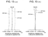
- objective lens OBJ Owing to the actions of the ring-shaped zone structure serving as a diffractive structure that is formed on a light flux entering surface (Third surface in Table 3), objective lens OBJ is corrected almost perfectly in terms of spherical chromatic aberration within a range of a wavelength of 407.5 ⁇ 10 nm as shown in Fig. 13 (a). Due to this, occurrence of spherical chromatic aberration in the system combined with the chromatic aberration correcting element CA was controlled to be relatively small as shown in Fig. 13 (b).
- wave front aberration of the objective lens OBJ for wavelength 407.5 + 10 nm is 0.003 ⁇ rms
- wave front aberration of the combined system of the chromatic aberration correcting element CA and the objective lens OBJ for wavelength 407.5 + 10 nm is 0.041 ⁇ rms.
- a back focus of the objective lens OBJ is longer than wavelength 417.5 nm by about 2.0 ⁇ m, but changes of a back focus for wavelength changes are corrected substantially perfectly by the combination with the chromatic aberration correcting element CA.
- spherical chromatic aberration remaining on the chromatic aberration correcting element CA is not more than 0.002 ⁇ rms within a range of a wavelength of 407.5 ⁇ 10 nm. Therefore, coma caused by deviation of ⁇ 0.5 mm between the objective lens OBJ and the chromatic aberration correcting element CA is almost zero, for a range of a wavelength of 407.5 ⁇ 10 nm, and excellent tracking characteristics are obtained.
- values described in Items in the present example are as follows.
- Lens data of the optical system for an optical pickup device in Example 4 are shown in Table 4.
- the present example is one preferable as optical system OS for an optical pickup device shown in Fig. 7, and it is composed of objective lens OBJ and coupling lens CUL that converts a divergent light flux emitted from the light source into a parallel light flux.
- Each of the objective lens OBJ and the coupling lens CUL is a plastic lens.
- the coupling lens CUL is designed so that it may have no aberration within a diameter of 3.4 mm on its surface where a light flux emerges (Second surface in Table 4).
- spherical aberration of the objective lens OBJ for a wavelength of 407.5 + 10 nm is made to be under, as shown in Fig. 14 (a). Due to this, in the system where coupling lens CUL is combined with the objective lens, spherical aberration caused by changes in a degree of divergence of the light flux advancing to objective lens OBJ from the coupling lens CUL resulting from the changes of a wavelength of a semiconductor laser is eliminated properly, as shown in Fig. 14 (b).
- wave front aberration of the objective lens OBJ for wavelength 407.5 + 10 nm is 0.063 ⁇ rms
- wave front aberration of the combined system of the coupling lens CUL and the objective lens OBJ for wavelength 407.5 + 10 nm is 0.012 ⁇ rms.
- a back focus of the objective lens OBJ is longer than wavelength 417.5 nm by about 2.5 ⁇ m, but changes of a back focus for wavelength changes are corrected substantially perfectly by the combination with the coupling lens CUL.
- spherical chromatic aberration remaining on the coupling lens CUL is not more than 0.001 ⁇ rms within a range of a wavelength of 407.5 ⁇ 10 nm. Therefore, coma caused by deviation of ⁇ 0.5 mm between the objective lens OBJ and the coupling lens CUL is almost zero, for a range of a wavelength of 407.5 ⁇ 10 nm, and excellent tracking characteristics are obtained.
- values described in Items in the present example are as follows.
- Lens data of the optical system for an optical pickup device in the present example are shown in Table 5.
- the present example is one preferable as optical system OS for an optical pickup device shown in Fig. 8, and it is composed of objective lens OBJ and of expander lens EXP that is arranged in the parallel light flux of the light source and converts a diameter of the parallel light flux to lead it to the objective lens OBJ.
- Each of the objective lens OBJ and the expander lens EXP is a plastic lens.
- the expander lens EXP is designed so that it may have no aberration within a diameter of 3.4 mm on its surface where a light flux emerges (Fourth surface in Table 5).
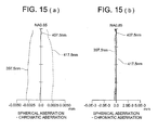
- spherical aberration of the objective lens OBJ for a wavelength of 407.5 + 10 nm is made to be under, as shown in Fig. 15 (a). Due to this, in the system where expander lens EXP is combined with the objective lens, spherical aberration caused by changes in a degree of divergence of the light flux advancing to objective lens OBJ from the expander lens EXP resulting from the changes of a wavelength of a semiconductor laser is eliminated properly, as shown in Fig. 15 (b).
- wave front aberration of the objective lens OBJ for wavelength 407.5 + 10 nm is 0.063 ⁇ rms
- wave front aberration of the combined system of the expander lens EXP and the objective lens OBJ for wavelength 407.5 + 10 nm is 0.011 ⁇ rms.
- a back focus of the objective lens OBJ is longer than wavelength 417.5 nm by about 2.5 ⁇ m, but changes of a back focus for wavelength changes are corrected substantially perfectly by the combination with the expander lens EXP.
- spherical chromatic aberration remaining on the expander lens EXP is not more than 0.002 ⁇ rms within a range of a wavelength of 407.5 ⁇ 10 nm. Therefore, coma caused by deviation of ⁇ 0.5 mm between the objective lens OBJ and the expander lens EXP is almost zero, for a range of a wavelength of 407.5 ⁇ 10 nm, and excellent tracking characteristics are obtained.
- values described in Items in the present example are as follows.
- Lens data of the optical system for an optical pickup device in Example 6 are shown in Table 6.
- the present example is represented by optical system OS for an optical pickup device wherein an optical element on which an optical path difference providing structure is formed as shown in Fig. 4 is used in place of objective lens OBJ of optical system OS for an optical pickup device shown in Fig. 1.
- the optical system OS for an optical pickup device is composed of objective lens OBJ and chromatic aberration correcting elements CA arranged in the objective lens OBJ and a parallel light flux from a light source.
- Each of the objective lens OBJ and chromatic aberration correcting element CA is designed so that it may have no aberration within a diameter of 3.4 mm on its surface where a light flux emerges (second surface in Table 6).
- spherical aberration is caused in the under-corrected direction at a wavelength of 417.5 nm as shown in Fig. 16 (a), by an effect of a ring-shaped zonal structure serving as a phase difference providing structure formed on a light flux entering surface (the third surface in 6-1), and wavefront aberration in that case is 0.054 ⁇ rms.
- chromatic aberration correcting elements CA When chromatic aberration correcting elements CA is combined with the foregoing, an emerging light turns out to be a converged light and spherical aberration is caused in the over-corrected direction in the objective lens OBJ by an effect of a ring-shaped zonal structure serving as a diffractive structure formed on a light flux entering surface (the first surface in Table 6-1) of the chromatic aberration correcting elements CA.
- Fig. 17 (a) shows wavefront aberration including defocus components that is caused when a light flux with wavelength 408.5 nm enters objective lens OBJ
- Fig. 17 (b) shows wavefront aberration including defocus components that is caused when light with wavelength 408.5 nm enters a compound system of the chromatic aberration correcting elements CA and objective lens OBJ
- Figs. 17 (a) and 17 (b) show that defocus components of objective lens OBJ caused by changes in a wavelength of an incident light flux are corrected properly by an effect of a ring-shaped zonal structure serving as a diffractive structure of the chromatic aberration correcting elements CA.
- spherical chromatic aberration remaining on the chromatic aberration correcting elements CA is 0.002 ⁇ rms or less in a wavelength range of 407.5 ⁇ 10 nm. Therefore, coma caused by the deviation of optical axis of 0.5 mm between objective lens OBJ and the chromatic aberration correcting elements CA is substantially zero, and excellent tracking characteristics are obtained.
- the invention makes it possible to provide an optical system for an optical pickup device that is housed in the optical pickup device employing a violet light source having a short wavelength, wherein, when a wavelength of an incident light is changed, frequency of occurrence of coma is sufficiently small, and further, even when the objective lens is decentered for the chromatic aberration correcting element in the direction perpendicular to the optical axis when a wavelength of the incident light is changed, frequency of occurrence of spherical aberration is sufficiently small. It is further possible to provide an objective lens capable of being applied to the optical system of the optical pickup device and the optical pickup device in which the optical system for the optical pickup device and the objective lens are housed.
Applications Claiming Priority (2)
| Application Number | Priority Date | Filing Date | Title |
|---|---|---|---|
| JP2002337788 | 2002-11-21 | ||
| JP2002337788 | 2002-11-21 |
Publications (2)
| Publication Number | Publication Date |
|---|---|
| EP1422703A2 true EP1422703A2 (de) | 2004-05-26 |
| EP1422703A3 EP1422703A3 (de) | 2008-01-09 |
Family
ID=32212117
Family Applications (1)
| Application Number | Title | Priority Date | Filing Date |
|---|---|---|---|
| EP03257226A Withdrawn EP1422703A3 (de) | 2002-11-21 | 2003-11-17 | Objektivlinse, optisches System und optisches Abtastgerät |
Country Status (6)
| Country | Link |
|---|---|
| US (1) | US7031076B2 (de) |
| EP (1) | EP1422703A3 (de) |
| JP (1) | JP2009217929A (de) |
| KR (1) | KR20040045307A (de) |
| CN (1) | CN1278323C (de) |
| TW (1) | TW200502670A (de) |
Cited By (2)
| Publication number | Priority date | Publication date | Assignee | Title |
|---|---|---|---|---|
| EP1569212A3 (de) * | 2004-02-27 | 2008-01-09 | Konica Minolta Opto, Inc. | Objektivsystem, optisches Abtastgerät und optisches Informationsaufzeichnungs- und -wiedergabegerät |
| CN102498517A (zh) * | 2009-09-18 | 2012-06-13 | 柯尼卡美能达精密光学株式会社 | 物镜、光拾取装置及光信息记录再生装置 |
Families Citing this family (18)
| Publication number | Priority date | Publication date | Assignee | Title |
|---|---|---|---|---|
| WO2004032127A2 (en) * | 2002-09-30 | 2004-04-15 | Konica Minolta Holdings, Inc. | Optical element, objective optical element and optical pickup device |
| JP4119780B2 (ja) * | 2003-03-28 | 2008-07-16 | Hoya株式会社 | 成形体の製造方法、製造装置及び光ピックアップ用対物レンズ |
| JP4338534B2 (ja) * | 2003-05-09 | 2009-10-07 | パイオニア株式会社 | 光ピックアップ、光学部材及び情報再生装置 |
| WO2005006321A1 (ja) * | 2003-07-11 | 2005-01-20 | Matsushita Electric Industrial Co., Ltd. | 光ピックアップ用レンズ装置及びそれを用いた情報記録再生装置 |
| WO2005101393A1 (ja) * | 2004-04-13 | 2005-10-27 | Konica Minolta Opto, Inc. | 光ピックアップ装置用の対物光学系、光ピックアップ装置、光情報記録媒体のドライブ装置、集光レンズ、及び光路合成素子 |
| WO2006046465A1 (ja) * | 2004-10-29 | 2006-05-04 | Konica Minolta Opto, Inc. | 対物レンズ、光ピックアップ装置及び光ディスクドライブ装置 |
| KR100680171B1 (ko) | 2005-01-25 | 2007-02-08 | 삼성전자주식회사 | 호환형 광픽업 |
| JP4404092B2 (ja) * | 2005-02-10 | 2010-01-27 | コニカミノルタオプト株式会社 | 対物レンズ、光ピックアップ装置及び光情報記録再生装置 |
| JP4803836B2 (ja) * | 2005-08-08 | 2011-10-26 | パナソニック株式会社 | 撮像光学系 |
| JP4591329B2 (ja) * | 2005-11-22 | 2010-12-01 | ソニー株式会社 | 光ピックアップ装置 |
| CN101405800B (zh) * | 2006-03-20 | 2011-04-13 | 松下电器产业株式会社 | 光学头及光盘装置 |
| JP2008165968A (ja) * | 2006-12-29 | 2008-07-17 | Matsushita Electric Ind Co Ltd | アフォーカルレンズ、光学ヘッド、光ディスク装置、及び光情報機器 |
| US8121012B2 (en) | 2008-11-19 | 2012-02-21 | Hoya Corporation | Objective lens and optical information recording/reproducing apparatus |
| JPWO2011033786A1 (ja) * | 2009-09-17 | 2013-02-07 | パナソニック株式会社 | 光ピックアップ光学系 |
| JP2011119000A (ja) * | 2009-12-07 | 2011-06-16 | Hitachi-Lg Data Storage Inc | 光ディスク装置およびデフォーカス補正方法 |
| CN107450155B (zh) * | 2016-05-31 | 2021-10-08 | 扬明光学股份有限公司 | 光学镜头 |
| US10222615B2 (en) * | 2017-05-26 | 2019-03-05 | Microsoft Technology Licensing, Llc | Optical waveguide with coherent light source |
| CN107894655B (zh) * | 2017-11-07 | 2023-07-14 | 东莞市美光达光学科技有限公司 | 一种采用环形孔径衍射光学的手机镜头模组 |
Citations (5)
| Publication number | Priority date | Publication date | Assignee | Title |
|---|---|---|---|---|
| EP1022731A2 (de) * | 1999-01-22 | 2000-07-26 | Konica Corporation | Optische Abtastvorrichtung und Verfahren zur Informationaufzeichnung und Informationswiedergabe |
| US20010008512A1 (en) * | 1999-12-28 | 2001-07-19 | Asahi Kogaku Kogyo Kabushiki Kaisha | Objective lens for optical pick-up |
| EP1154417A2 (de) * | 2000-05-12 | 2001-11-14 | Konica Corporation | Optische Abtastvorrichtung |
| EP1202260A2 (de) * | 2000-10-26 | 2002-05-02 | Konica Corporation | Optisches Abtastgerät und Objektivlinse |
| EP1202259A2 (de) * | 2000-10-30 | 2002-05-02 | Konica Corporation | Objektivlinse, lichtkonvergierendes optisches System, optisches Abtastgerät, und Aufzeichnungs- / Wiedergabegerät |
Family Cites Families (3)
| Publication number | Priority date | Publication date | Assignee | Title |
|---|---|---|---|---|
| JP3794229B2 (ja) * | 1999-01-22 | 2006-07-05 | コニカミノルタホールディングス株式会社 | 光ピックアップ装置、この光ピックアップ装置を備えた記録再生装置、情報の記録再生方法、及び光ピックアップ装置用対物レンズ |
| EP1471514A3 (de) * | 2003-04-22 | 2006-10-04 | Konica Minolta Opto, Inc. | Optische Abtastvorrichtung und Vorrichtung zur optischen Aufnahme und Wiedergabe von Information, Aufweitungslinse, Kopplungslinse und optisches Element zur Korrektur chromatischer Aberration |
| TW200508651A (en) * | 2003-06-09 | 2005-03-01 | Konica Minolta Opto Inc | Optical system for optical pickup apparatus, optical pickup apparatus, optical information recording and/or reproducing apparatus and aberration-correcting element for optical pickup apparatus |
-
2003
- 2003-11-14 TW TW092131997A patent/TW200502670A/zh unknown
- 2003-11-17 EP EP03257226A patent/EP1422703A3/de not_active Withdrawn
- 2003-11-18 US US10/714,614 patent/US7031076B2/en not_active Expired - Fee Related
- 2003-11-18 KR KR1020030081305A patent/KR20040045307A/ko not_active Application Discontinuation
- 2003-11-18 CN CNB2003101165982A patent/CN1278323C/zh not_active Expired - Fee Related
-
2009
- 2009-05-20 JP JP2009122135A patent/JP2009217929A/ja active Pending
Patent Citations (5)
| Publication number | Priority date | Publication date | Assignee | Title |
|---|---|---|---|---|
| EP1022731A2 (de) * | 1999-01-22 | 2000-07-26 | Konica Corporation | Optische Abtastvorrichtung und Verfahren zur Informationaufzeichnung und Informationswiedergabe |
| US20010008512A1 (en) * | 1999-12-28 | 2001-07-19 | Asahi Kogaku Kogyo Kabushiki Kaisha | Objective lens for optical pick-up |
| EP1154417A2 (de) * | 2000-05-12 | 2001-11-14 | Konica Corporation | Optische Abtastvorrichtung |
| EP1202260A2 (de) * | 2000-10-26 | 2002-05-02 | Konica Corporation | Optisches Abtastgerät und Objektivlinse |
| EP1202259A2 (de) * | 2000-10-30 | 2002-05-02 | Konica Corporation | Objektivlinse, lichtkonvergierendes optisches System, optisches Abtastgerät, und Aufzeichnungs- / Wiedergabegerät |
Cited By (3)
| Publication number | Priority date | Publication date | Assignee | Title |
|---|---|---|---|---|
| EP1569212A3 (de) * | 2004-02-27 | 2008-01-09 | Konica Minolta Opto, Inc. | Objektivsystem, optisches Abtastgerät und optisches Informationsaufzeichnungs- und -wiedergabegerät |
| US7460460B2 (en) | 2004-02-27 | 2008-12-02 | Konica Minolta Opto, Inc. | Objective optical system, optical pickup apparatus and optical information recording and reproducing apparatus |
| CN102498517A (zh) * | 2009-09-18 | 2012-06-13 | 柯尼卡美能达精密光学株式会社 | 物镜、光拾取装置及光信息记录再生装置 |
Also Published As
| Publication number | Publication date |
|---|---|
| US7031076B2 (en) | 2006-04-18 |
| KR20040045307A (ko) | 2004-06-01 |
| US20040100703A1 (en) | 2004-05-27 |
| CN1503247A (zh) | 2004-06-09 |
| TW200502670A (en) | 2005-01-16 |
| JP2009217929A (ja) | 2009-09-24 |
| EP1422703A3 (de) | 2008-01-09 |
| CN1278323C (zh) | 2006-10-04 |
Similar Documents
| Publication | Publication Date | Title |
|---|---|---|
| US6876501B2 (en) | Objective lens, coupling lens, light converging optical system, and optical pick-up apparatus | |
| EP1986189B1 (de) | Optische Lesekopfvorrichtung | |
| US7382709B2 (en) | Objective lens, optical element, optical pick-up apparatus and optical information recording and/or reproducing apparatus equipped therewith | |
| EP1422703A2 (de) | Objektivlinse, optisches System und optisches Abtastgerät | |
| US6865025B2 (en) | Aberration compensating optical element, optical system, optical pickup device, recorder and reproducer | |
| US7920456B2 (en) | Objective lens for optical pickup device, optical pickup device and optical information recording/reproducing apparatus | |
| EP1202259A2 (de) | Objektivlinse, lichtkonvergierendes optisches System, optisches Abtastgerät, und Aufzeichnungs- / Wiedergabegerät | |
| US6665130B2 (en) | Objective lens, optical pickup apparatus and recording and/or reproducing apparatus | |
| US6927923B2 (en) | Objective lens, converging optical system, optical pickup apparatus and recording and/or reproducing apparatus | |
| US6950383B2 (en) | Objective lens, light converging optical system, optical pickup apparatus, and recording and/or reproducing apparatus | |
| JP2004185797A (ja) | 光ピックアップ装置用光学系、光ピックアップ装置及び対物レンズ | |
| US7110344B2 (en) | Objective lens, optical pickup apparatus, and recording and/or reproducing apparatus | |
| US7515523B2 (en) | Optical system for optical pickup apparatus, optical pickup apparatus, optical information recording and/or reproducing apparatus and aberration-correcting element for optical pickup apparatus | |
| US20050122883A1 (en) | Optical pickup apparatus and optical information recording and/or reproducing apparatus | |
| US20040047040A1 (en) | Objective lens and optical pickup device | |
| JP4280896B2 (ja) | 光ピックアップ装置用光学系、光ピックアップ装置、光情報記録再生装置及び色収差補正素子 | |
| EP1569212A2 (de) | Objektivsystem, optisches Abtastgerät und optisches Informationsaufzeichnungs- und -wiedergabegerät | |
| US20060181744A1 (en) | Optical unit and optical pickup apparatus | |
| US20070263523A1 (en) | Objective lens optical system and optical pickup optical system |
Legal Events
| Date | Code | Title | Description |
|---|---|---|---|
| PUAI | Public reference made under article 153(3) epc to a published international application that has entered the european phase |
Free format text: ORIGINAL CODE: 0009012 |
|
| AK | Designated contracting states |
Kind code of ref document: A2 Designated state(s): AT BE BG CH CY CZ DE DK EE ES FI FR GB GR HU IE IT LI LU MC NL PT RO SE SI SK TR |
|
| AX | Request for extension of the european patent |
Extension state: AL LT LV MK |
|
| PUAL | Search report despatched |
Free format text: ORIGINAL CODE: 0009013 |
|
| AK | Designated contracting states |
Kind code of ref document: A3 Designated state(s): AT BE BG CH CY CZ DE DK EE ES FI FR GB GR HU IE IT LI LU MC NL PT RO SE SI SK TR |
|
| AX | Request for extension of the european patent |
Extension state: AL LT LV MK |
|
| AKX | Designation fees paid | ||
| REG | Reference to a national code |
Ref country code: DE Ref legal event code: 8566 |
|
| STAA | Information on the status of an ep patent application or granted ep patent |
Free format text: STATUS: THE APPLICATION IS DEEMED TO BE WITHDRAWN |
|
| 18D | Application deemed to be withdrawn |
Effective date: 20080710 |