EP1422532A2 - Method and apparatus for determining effective power consumed by a capacitor - Google Patents
Method and apparatus for determining effective power consumed by a capacitor Download PDFInfo
- Publication number
- EP1422532A2 EP1422532A2 EP03026762A EP03026762A EP1422532A2 EP 1422532 A2 EP1422532 A2 EP 1422532A2 EP 03026762 A EP03026762 A EP 03026762A EP 03026762 A EP03026762 A EP 03026762A EP 1422532 A2 EP1422532 A2 EP 1422532A2
- Authority
- EP
- European Patent Office
- Prior art keywords
- capacitor
- effective power
- periodic voltage
- temperatures
- capacitance
- Prior art date
- Legal status (The legal status is an assumption and is not a legal conclusion. Google has not performed a legal analysis and makes no representation as to the accuracy of the status listed.)
- Granted
Links
Images





Classifications
-
- G—PHYSICS
- G01—MEASURING; TESTING
- G01R—MEASURING ELECTRIC VARIABLES; MEASURING MAGNETIC VARIABLES
- G01R21/00—Arrangements for measuring electric power or power factor
- G01R21/02—Arrangements for measuring electric power or power factor by thermal methods, e.g. calorimetric
-
- G—PHYSICS
- G01—MEASURING; TESTING
- G01R—MEASURING ELECTRIC VARIABLES; MEASURING MAGNETIC VARIABLES
- G01R21/00—Arrangements for measuring electric power or power factor
- G01R21/133—Arrangements for measuring electric power or power factor by using digital technique
- G01R21/1331—Measuring real or reactive component, measuring apparent energy
Definitions
- the present invention relates to a method of calculating effective power relating to a capacitor, a method of measuring effective power consumed by the capacitor, a capacitor selection method, a calculator for calculating the effective power consumed by the capacitor, and a recording medium storing the calculation program therefor.
- capacitors have been used for an electric circuit, such as a snubber circuit of a switching power supply, a horizontal resonant circuit of a color television, and other suitable circuits, where a predetermined periodic pulse voltage of a predetermined waveform other than a sine waveform is applied.
- an allowable power capacity of the capacitor so as to suppress the heat generated by the capacitor below the allowable capacity, whereby the capacitors are prevented from a trouble (decreased life or destruction due to thermal runaway) caused by self heating due to a dielectric loss.
- apparent power that can be easily measured is used as the allowable power capacity. This apparent power is obtained by multiplying the effective value of a voltage applied to the capacitor by the effective value of a current flowing into the capacitor. If the waveform of the voltage applied to the capacitor is a sine waveform, the apparent power can be measured relatively easily.
- Patent Document 1 has the following problems.
- the sum of effective powers Pe n calculated for the harmonics is unequal to the product of the sum of the apparent powers Pa n and the dielectric tangent ( ⁇ (effective powers Pe n ) ⁇ dielectric tangent ⁇ ⁇ (apparent powers Pa n )).
- the apparent power Pa cannot be regarded as a substitute characteristic of the effective power Pe consumed by the capacitor.
- preferred embodiments of the present invention provide a method of calculating effective power relating to a capacitor for calculating effective power actually consumed by the capacitor from the capacitance, dielectric tangent, and periodic voltage waveform of the capacitor.
- the present invention also provides a method of measuring the effective power consumed by the capacitor, a capacitor selection method, a calculator for calculating the effective power relating to the capacitor, and a recording medium storing the calculation program therefor.
- a preferred embodiment of the present invention provides a method of calculating effective power relating to a capacitor, which comprises the steps of obtaining an equilibrium temperature of the capacitor for each of a plurality of sine waves, substituting a first capacitance and a first dielectric tangent of the capacitor for each of the equilibrium temperatures into the following equation.
- Pe tan ⁇ 1 +(tan ⁇ ) 2 ⁇ fCb 2
- first effective power for each of the equilibrium temperatures.
- second effective power (a calculation value) corresponding to the periodic voltage for each of the provisional temperature is obtained.
- This method further comprises the steps of determining a temperature at which the first effective power (the regression value) becomes equivalent to the second effective power (the calculation value) as a target equilibrium temperature of the capacitor, and determining the first and second effective powers corresponding to this target equilibrium temperature as a target effective power corresponding to the periodic voltage.
- the step of calculating the second effective power (the calculation value)
- Fourier expansion is performed for the periodic voltage, and effective power is calculated for each of harmonics. Then, the sum of the calculated effective powers of the harmonics is determined as the second effective power (the calculation value) corresponding to the periodic voltage.
- Another preferred embodiment of the present invention provides a method of measuring effective power consumed by a capacitor.
- a periodic voltage is applied to the capacitor and the waveform of the periodic voltage applied to both ends of the capacitor is measured. Further, the effective power consumed by the capacitor is calculated from the measured waveform of the periodic voltage, by using the method of calculating the effective power relating to the capacitor.
- first effective power for each of the equilibrium temperatures is obtained.
- second effective power (a calculation value) corresponding to the periodic voltage is obtained for each of the provisional temperatures.
- This method further comprises the steps of determining a temperature at which the first effective power (the regression value) becomes equivalent to the second effective power (the calculation value) as a target equilibrium temperature of the capacitor, determining the first and second effective powers corresponding to this target equilibrium temperature as a target effective power corresponding to the periodic voltage, and comparing the target effective power corresponding to the periodic voltage with an allowable power capacity of the capacitor for determining whether or not the capacitor is available.
- the calculation apparatus comprises a calculator.
- This calculator stores data on capacitances and dielectric tangents of a plurality of capacitors. The capacitances and the dielectric tangents are determined based on a voltage characteristic, a frequency characteristic, and a temperature characteristic of the capacitors.
- This calculator also stores data on first effective power (a regression power) for each of equilibrium temperatures of the capacitors.
- first effective power a regression power
- the calculator calculates second effective power (a calculation value) at a plurality of provisional temperatures from the input waveform of the periodic voltage.
- the calculator determines a predetermined temperature at which the first effective power (the regression value) becomes equivalent to the second effective power (the calculation value) as a target equilibrium temperature of the capacitor.
- the calculator further determines the first effective power and the second effective power corresponding to the target equilibrium temperature as a target effective power corresponding to the periodic voltage.
- the calculator compares a stored allowable power of the capacitor with the target effective power corresponding to the periodic voltage for determining whether or not the capacitor is available.
- Another preferred embodiment of the present invention provides a recording medium storing the program for calculating effective power relating to a capacitor by using a computer.
- the calculation program stores data on capacitances and dielectric tangents of a plurality of capacitors. The capacitances and the dielectric tangents are determined based on a voltage characteristic, a frequency characteristic, and a temperature characteristic of the capacitors.
- the calculation program also stores data on first effective power (a regression value) for each of equilibrium temperatures of the capacitors.
- first effective power a regression value
- the program calculates second effective power (a calculation value) at a plurality of provisional temperatures from the input waveform of the periodic voltage.
- the calculation program determines a predetermined temperature at which the first effective power (the regression value) becomes equivalent to the second effective power (the calculation value) as a target equilibrium temperature of the capacitor.
- the calculation program further determines the first effective power and the second effective power corresponding to the target equilibrium temperature as a target effective power corresponding to the periodic voltage.
- the calculation program compares a stored allowable power of the capacitor to the target effective power corresponding with the periodic voltage for determining whether or not the capacitor is available.
- the effective power consumed by the capacitor quickly, precisely, and stably. Further, it is possible to obtain the effective power of the capacitor, where the effective power corresponding to a predetermined periodic voltage applied to the capacitor, even though an electric circuit is not actually provided.
- a method of calculating effective power relating to a capacitor, a method of measuring the effective power consumed by the capacitor, a capacitor selection method, a calculation apparatus for calculating the effective power relating to the capacitor, and a recording medium storing the calculation program therefor according to preferred embodiments of the present invention will now be described with reference to the accompanying drawings.
- an electric circuit to which a periodic voltage is applied is prepared.
- a snubber circuit of a switching field effect transistor (FET) of a switching power supply is used as the electric circuit.
- FET switching field effect transistor
- a ceramic capacitor of which capacitance value is 470 pF and rated voltage is DC 1 kV is used as a capacitor for evaluation.
- a periodic pulse voltage V(t) is applied to the ceramic capacitor.
- the waveform of the periodic pulse voltage V(t) is determined so as not to be a sine waveform.
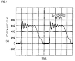
- the waveform of the periodic pulse voltage V(t) applied to both ends of the ceramic capacitor is measured by using an oscilloscope. Subsequently, trapezoidal waves with a frequency of 99.6 kHz and a peak to peak (p-p) value V of 778 volts are obtained, as shown in Fig. 1.
- the waveform of the periodic pulse voltage V(t) applied to the both ends of the ceramic capacitor is subjected to Fourier expansion.
- the periodic pulse voltage V(t) having predetermined periodicity and no sine waves is Fourier-expanded in terms of sine and cosine-wave series of high-order frequency components, as shown in Equation (1).
- V(t) V 0 + ⁇ (a n cos(n ⁇ t)+b n sin(n ⁇ t) ⁇
- an equivalent circuit diagram of the capacitor shows a capacitor C in series with an equivalent series resistance R.
- the capacitance of the capacitor is determined as C(F)
- the equivalent series resistance thereof is determined as R( ⁇ )
- the impedance thereof is determined as Z( ⁇ )
- the phase angle thereof is determined as ⁇
- the angular speed of a high-frequency sine-wave voltage is determined as ⁇ (rad/s)
- Equation (2) is true.
- Equation (2) leads to Equation (4).
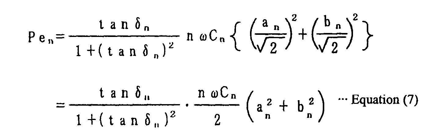
- Equation (1) the effective value of an n-order harmonic-component voltage is determined as Vrms in Equation (1). Since the cosine-wave term and the sine-wave term are independent of each other, Equations (5) and (6) is obtained.
- Equation (7) the effective power Pe n of the n-order harmonic component is expressed in Equation (7).
- C n means the capacitance of the capacitor and tan ⁇ n means a dielectric tangent (tan ⁇ ) thereof, where the n-order harmonic wave is n ⁇ .
- Equation (8) Equation (8)
- capacitors have very high insulation resistance values of 100 M ⁇ or more. Therefore, effective power due to the DC component V 0 is negligible. Therefore, the effective power Pe of the periodic pulse voltage V(t) is calculated by summation of effective powers Pe n of harmonics, as shown in Equation (9).
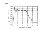
- Fig. 2 is a graph illustrating a voltage waveform subjected to Fourier expansion.
- n Frequency Voltage [V] [kHz] a n b n 1 100 -174.
- C n and tan ⁇ n are functions of a temperature, a voltage, and a frequency. If a voltage waveform applied to the both ends of the capacitor is determined, the voltage and frequency are determined by Fourier expansion. However, the temperature is not determined only by the voltage waveform. Namely, if a current flows into the capacitor, effective power consumed by the capacitor changes into thermal energy, such that heat is liberated. Subsequently, the temperature of the capacitor rises to a predetermined point where the heating value and heatsinking value of the capacitor reach equilibrium.
- the value of the effective power is required for determining the temperature of the capacitor, and the functions C n and tan ⁇ n are required for determining the effective power value.
- this temperature is a temperature whereat the effective power Pe and the heatsinking value reach equilibrium.
- the equilibrium temperature of the capacitor where the atmospheric temperature is 25 °C, is measured by using a plurality of high-frequency sine waves. Since C n and tan ⁇ n are the functions of the temperature, voltage, and frequency, they are determined by sine-wave conditions (the voltage and frequency) and the equilibrium temperature (a measured value). Since the waveform of the high-frequency voltage applied to the capacitor is sine waves, Fourier expansion is unnecessary to obtain the sum of effective powers Pe n .
- P e tan ⁇ 1 +(tan ⁇ ) 2 ⁇ ⁇ f C b 2
- the voltage value and frequency of the capacitor are obtained from the waveform of the periodic pulse voltage applied to the both ends of the capacitor. Since the equilibrium temperature of the capacitor determined by this periodic-pulse-voltage waveform is unknown, a plurality of provisional temperatures are determined and C n and tan ⁇ n for each of the provisional temperatures are determined. If the periodic pulse voltage have sine waves, where Fourier expansion is unnecessary to obtain the sum of effective powers Pe n , these C n and tan ⁇ n are substituted into Equation (8) for calculating effective power Pe (a calculation value). Subsequently, the effective power Pe (the calculation value) at each temperature corresponding to the periodic pulse voltage is obtained. The calculation results are shown in the right column of Table 2.
- the equilibrium temperature of the capacitor is a temperature at which one of the effective powers Pe (the calculation values) is equivalent to one of the effective powers Pe (the regression values) obtained from the regression formula. These effective powers are equivalent to a target effective power Pe corresponding to the periodic-pulse voltage waveform.
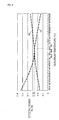
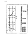
- Fig. 4 is a graph illustrating the effective powers Pe (the regression values) obtained from the regression formula by using the actual measured values of the sine waves (see solid line 10). This graph also illustrates the effective powers Pe (the calculation values) obtained by Fourier analysis on the periodic pulse-voltage waveform (see solid line 11).
- the intersection point of the solid line 10 and the solid line 11 indicates the target effective power Pe corresponding to the periodic pulse voltage and the equilibrium temperature of the capacitor.
- the solid line 10 is a curve unique to this capacitor.
- the solid line 11 is a curve depending on the frequency of the period pulse-voltage waveform. Namely, the distance between the solid line 11 and the origin, and the equilibrium temperature indicated by the intersection point of the solid line 11 and the solid line 10 increase, as the order n of the n-order harmonic increases.
- the equilibrium temperature of the capacitor is 52.8°C and the effective power Pe consumed by the capacitor is 0.27 W.
- the equilibrium temperature of the capacitor is 51.3 ° C, which is measured by a K thermocouple with a diameter of 0.1 mm.
- the above-described embodiment allows for obtaining the effective power Pe consumed by the ceramic capacitor used for the snubber circuit to which the periodic pulse voltage V(t) having the trapezoidal waves is applied. Subsequently, the time required for measuring the effective power Pe consumed by the ceramic capacitor is significantly reduced.
- Fig. 5 shows a flexible disk 10 functioning as a recording medium storing a capacitor selection method and a program for calculating effective power relating to the capacitor.
- a CD-ROM or other suitable medium can be used in place of the flexible disk 10.
- a computer 20 transfers and installs the capacitor selection method and the program for calculating the effective power relating to the capacitor onto a CPU provided therein to perform calculations.
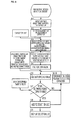
- Fig. 6 is a flowchart illustrating an example program installed on the computer 20.
- the flexible disk 10 stores data on the names of a plurality of capacitors, the allowable power capacities, temperature characteristics of capacitances C n and dielectric tangents tan ⁇ n , voltage characteristics and frequency characteristics of the capacitors, and a program that can set a predetermined periodic-voltage waveform.
- the flexible disk 10 also stores a method of measuring effective power consumed by a capacitor shown in the flowchart of Fig. 6 and a program relating to the capacitor selection method.
- a display of the computer 20 When this program is started, an initial image shown in Fig. 7 is produced on a display of the computer 20.
- Voltage waveform data input that is, a voltage-waveform determination part where a voltage applied to the capacitor is determined, is displayed at the upper-left comer of a screen of the display.
- the waveform of a periodic voltage applied to the capacitor is determined through a text file, an image file, or a mouse of the computer 20 (see step S of the flowchart of Fig. 6).
- a list of the capacitors is displayed on the lower part of the screen. This list shows the series names, product numbers, rated voltages, and nominal capacitances of the capacitors.
- a predetermined data file is selected among a plurality of data files stored in the computer 20, and numerical data on time and voltage is input to set a predetermined periodic voltage waveform.
- Image data on the periodic voltage waveform is input to the computer 20 directly from a measuring device connected thereto, from the measuring device connected thereto via a network, or via a recording medium such as a flexible disk storing the data generated by the measuring device. This image data is traced by using a mouse to set the periodic voltage waveform.
- an image shown in Fig. 10 is displayed on the screen.
- a predetermined capacitor for a theoretical design, or for an actual circuit is input by using a keyboard or the mouse of the computer 20. Namely, either a lead-terminal type or a chip lamination type is selected.
- the capacitance of a desired capacitor is input, as shown in Fig. 12, by using the keyboard or the mouse(see step S2 shown in the flowchart of Fig. 6).
- the CPU of the computer 20 selects information about a capacitor having the capacitance in accordance with the input capacitance (see step S3 shown in the flowchart of Fig. 6) from the list. Further, the CPU selects at least one capacitor having a rated voltage that can be used with the input periodic voltage waveform (see step S4 shown in the flowchart of Fig. 6).
- the CPU of the computer 20 performs Fourier expansion and calculation to obtain effective power, as shown in steps S5 and S6 in the flowchart of Fig. 6.
- the data on the temperature characteristics of the capacitances C n and dielectric tangents tan ⁇ n , and the voltage characteristics and the frequency characteristics of each of the capacitors that are installed on the computer 20 are transferred to the CPU of the computer 20 and used for the calculations.
- effective powers Pe at equilibrium temperatures of the capacitor selected at step S4 are obtained from regression values calculated from measured values for the sine waves (see the center column of Table 2). The equilibrium temperatures are obtained.
- the effective powers Pe are compared with the effective powers Pe obtained by Fourier analysis on the pulse waveforms for each of the provisional temperatures (see the right column of Table 2), and one of the effective powers Pe shown in the center column matches one of the effective powers Pe shown in the right column, as shown in Table 2.
- the equilibrium temperature at which both of the effective powers Pe match to each other is a target equilibrium temperature of the capacitor. And, the effective power then is the effective power Pe (a calculation value) consumed by the capacitor.
- step S7 it is determined whether or not the effective power (the calculation value) consumed by the capacitor falls within a predetermined range of the allowable power capacities of the capacitors (see step S7 shown in the flowchart of Fig. 6). If the effective power (the calculation value) consumed by the capacitor falls outside this range, it is determined that this capacitor is not available. If the effective power falls within this range, it is determined that this capacitor is available and the process proceeds to step S8 such that the capacitor is added to this selection list. Further, feedback is performed at step S10 till the results of determination on whether or not the capacitors are available are obtained for all the capacitors selected at step S4.
- the image of the capacitor selection list (a list showing the results of determination on availability) is displayed on the screen of the display, as shown in Fig. 13.
- This list also shows the effective powers (the calculation values) in percentages of the allowable power capacities.
- an available capacitor is selected and displayed only by inputting the nominal capacitance of a predetermined capacitor and the waveform of a periodic voltage applied to both ends of the capacitor.
- the above-described program can be stored in a recording medium, such as a CD-ROM. Therefore, via a CD-ROM recording a program to perform the method of preferred embodiments of the present invention, the program can be installed onto a personal computer, whereby the personal computer can function as a calculation device for calculating effective power passing through a capacitor.
- This program may be downloaded from a predetermined home page.
- the present invention is not limited to the above-described embodiment, but can be modified variously within the scope thereof.
- the ceramic capacitor is used, but various types of capacitors can be used as long as the temperature characteristics of capacitances and dielectric tangents, and the voltage characteristics and frequency characteristics of the capacitors are known.
- a periodic voltage with arbitrary waveform can be used including a trapezoidal wave, a square wave, and a sawtooth wave.
- the present invention can be used even though the waveform of the periodic voltage has sine waves.
Landscapes
- Engineering & Computer Science (AREA)
- Power Engineering (AREA)
- Physics & Mathematics (AREA)
- General Physics & Mathematics (AREA)
- Measurement Of Resistance Or Impedance (AREA)
- Fixed Capacitors And Capacitor Manufacturing Machines (AREA)
- Testing Electric Properties And Detecting Electric Faults (AREA)
Abstract
Description
- Pe
- : effective power
- tan δ
- : dielectric tangent
- C
- : capacitance
- f
- : frequency
- b
- : sine-wave amplitude
- Pe
- : effective power
- tan δ
- : dielectric tangent
- C
- : capacitance
- f
- : frequency
- a
- : cosine-wave amplitude
- b
- : sine-wave amplitude




| n | Frequency | Voltage [V] | |
| [kHz] | an | bn | |
| 1 | 100 | -174. 8 | 287.5 |
| 2 | 200 | 9.1 | 103.7 |
| 3 | 300 | -48.8 | 42.0 |
| 4 | 400 | -27.5 | 30.8 |
| 5 | 500 | -41.4 | 8.7 |
| 6 | 600 | -34.6 | 13.4 |
| 7 | 700 | -21.1 | 3.5 |
| 8 | 800 | -17.4 | -6.3 |
| 9 | 900 | -22.9 | -11.1 |
| 10 | 1000 | -16.7 | -7.8 |
| 11 | 1100 | - 9.6 | -10.1 |
| 12 | 1200 | - 6.2 | -15.4 |
| 13 | 1300 | -7.0 | -18.9 |
| 14 | 1400 | 0.8 | -18.0 |
| 15 | 1500 | 12.7 | -16.8 |
| 16 | 1600 | 25. 5 | -6.9 |
| 17 | 1700 | 13.6 | 11.5 |
| 18 | 1800 | -0.9 | 10.7 |
| 19 | 1900 | 0.3 | 6.7 |
| 20 | 2000 | -1.2 | 3.8 |
| 21 | 2100 | -3.7 | 1.3 |
| 22 | 2200 | -5.0 | 0.9 |
| 23 | 2300 | -2.3 | 0.3 |
| 24 | 2400 | -1.4 | -0.8 |
| 25 | 2500 | -2.8 | -3.8 |
| 26 | 2600 | -2.3 | -3.2 |
| 27 | 2700 | 0.1 | -2.3 |
| 28 | 2800 | 1.5 | -3.5 |
| 29 | 2900 | 2.4 | -4.8 |
| 30 | 3000 | 2.5 | -1.7 |
| 31 | 3100 | 3.5 | -0.7 |
| Equilibrium temperature | effective power Pe [W] | |
| of Capacitor [°C] | Regression value obtained from actual measured value for sine wave | Value obtained by Fourier analysis on pulse waveform |
| 40 | 0.166 | 0.527 |
| 41 | 0.175 | 0.502 |
| 42 | 0.184 | 0.477 |
| 43 | 0.193 | 0.453 |
| 44 | 0.202 | 0.430 |
| 45 | 0.210 | 0.408 |
| 46 | 0.218 | 0.387 |
| 47 | 0.226 | 0.367 |
| 48 | 0.234 | 0.348 |
| 49 | 0.242 | 0.330 |
| 50 | 0.249 | 0.313 |
| 51 | 0.257 | 0.296 |
| 52 | 0.264 | 0.281 |
| 52.2 | 0.265 | 0.278 |
| 52.4 | 0.267 | 0.275 |
| 52.6 | 0.268 | 0.272 |
| 52.8 | 0.270 | 0.270 |
| 53 | 0.271 | 0.267 |
| 54 | 0.278 | 0.253 |
| 55 | 0.285 | 0.241 |
| 56 | 0.291 | 0.229 |
| 57 | 0.298 | 0.218 |
| 58 | 0.304 | 0.208 |
| 59 | 0.3111 | 0.198 |
| 60 | 0.317 | 0.189 |
| 61 | 0.323 | 0.181 |
| 62 | 0.329 | 0.172 |
| 63 | 0.335 | 0.164 |
| 64 | 0.341 | 0.157 |
| 65 | 0.347 | 0.149 |
Claims (6)
- A method of calculating effective power relating to a capacitor, comprising the steps of:obtaining a equilibrium temperature of the capacitor for each of a plurality of sine waves, and substituting a first capacitance and a first dielectric tangent of the capacitor for each of the equilibrium temperatures into the following equation shown as:
- Pe
- : effective power
- tan δ
- : dielectric tangent
- C
- : capacitance
- f
- : frequency
- b
- : sine-wave amplitude
obtaining a voltage value and a frequency from the waveform of a periodic voltage applied to both ends of the capacitor, and setting a plurality of provisional temperatures, and obtaining a second capacitance and a second dielectric tangent for each of the provisional temperatures, and substituting the second capacitance and the second dielectric tangent into the following equation shown as:- Pe
- : effective power
- tan δ
- : dielectric tangent
- C
- : capacitance
- f
- : frequency
- a
- : cosine-wave amplitude
- b
- : sine-wave amplitude
determining a temperature at which the first effective power (the regression value) is equivalent to the second effective power (the calculation value) as a target equilibrium temperature of the capacitor; and determining the first and second effective powers corresponding to this target equilibrium temperature as a target effective power corresponding to the periodic voltage. - A method of calculating effective power relating to a capacitor according to Claim 1, wherein the step of calculating the second effective power (the calculation value) comprises the steps of:performing Fourier expansion for the periodic voltage;calculating effective power for each of harmonics; anddetermining the sum of the calculated effective powers of the harmonics as the second effective power (the calculation value) corresponding to the periodic voltage.
- A method of measuring effective power consumed by a capacitor, wherein a periodic voltage is applied to the capacitor, and the waveform of the periodic voltage applied to both ends of the capacitor is measured, and the effective power consumed by the capacitor is calculated from the measured waveform of the periodic voltage by using the method of calculating the effective power relating to the capacitor according to Claim 1 or Claim 2.
- A method of selecting a capacitor, comprising the steps of:obtaining an equilibrium temperature of the capacitor for each of a plurality of sine waves, and substituting a first capacitance and a first dielectric tangent of the capacitor for each of the equilibrium temperatures into the following equation shown as:
- Pe
- : effective power
- tan δ
- : dielectric tangent
- C
- : capacitance
- f
- : frequency
- b
- : sine-wave amplitude
obtaining a voltage value and a frequency from the waveform of a periodic voltage applied to both ends of the capacitor, and setting a plurality of provisional temperatures, and obtaining a second capacitance and a second dielectric tangent for each of the provisional temperatures, and substituting the second capacitance and the second dielectric tangent into the following equation shown as:- Pe
- : effective power
- tan δ
- : dielectric tangent
- C
- : capacitance
- f
- : frequency
- a
- : cosine-wave amplitude
- b
- : sine-wave amplitude
determining a temperature at which the first effective power (the regression value) is equivalent to the second effective power (the calculation value) as a target equilibrium temperature of the capacitor, and determining the first and second effective powers corresponding to this target equilibrium temperature as a target effective power corresponding to the periodic voltage; and
comparing the target effective power corresponding to the periodic voltage with an allowable power capacity of the capacitor in order to determine whether or not the capacitor is available. - A calculation apparatus for calculating effective power relating to a capacitor, comprising a calculator,
wherein the calculator stores data on a plurality of capacitors including capacitances and dielectric tangents thereof which are determined based on a voltage characteristic, a frequency characteristic, and a temperature characteristic of the capacitors, and data on first effective power (a regression value) for each of equilibrium temperatures of the capacitors,
wherein when a predetermined capacitance required for an electric circuit using one of the capacitors and the waveform of a periodic voltage applied to both ends of the capacitor are input, second effective power (a calculation value) at each of a plurality of provisional temperatures is calculated from the input waveform of the periodic voltage,
wherein the calculator determines a predetermined temperature at which the first effective power (the regression value) is equivalent to the second effective power (the calculation value) as a target equilibrium temperature of the capacitor,
wherein the calculator determines the first effective power and the second effective power corresponding to the target equilibrium temperature as a target effective power corresponding to the periodic voltage,
wherein the calculator compares a stored allowable power of the capacitor with the target effective power corresponding to the periodic voltage in order to determine whether or not the capacitor is available. - A recording medium storing a program for calculating effective power relating to a capacitor by using a computer,
wherein the program stores data on a plurality of capacitors including capacitances and dielectric tangents thereof which are determined based on a voltage characteristic, a frequency characteristic, and a temperature characteristic of the capacitors, and data on first effective power (a regression value) for each of equilibrium temperatures of the capacitors,
wherein when a predetermined capacitance required for an electric circuit using one of the capacitors and the waveform of a periodic voltage applied to both ends of the capacitor are input, the program calculates second effective power (a calculation value) at each of a plurality of provisional temperatures from the input waveform of the periodic voltage,
wherein the program determines a predetermined temperature at which the first effective power (the regression value) is equivalent to the second effective power (the calculation value) as a target equilibrium temperature of the capacitor,
wherein the program determines the first effective power and the second effective power corresponding to the target equilibrium temperature as a target effective power corresponding to the periodic voltage,
wherein the program compares a stored allowable power of the capacitor with the target effective power corresponding to the periodic voltage in order to determine whether or not the capacitor is available.
Applications Claiming Priority (4)
| Application Number | Priority Date | Filing Date | Title |
|---|---|---|---|
| JP2002339108 | 2002-11-22 | ||
| JP2002339108 | 2002-11-22 | ||
| JP2003373119 | 2003-10-31 | ||
| JP2003373119A JP4003735B2 (en) | 2002-11-22 | 2003-10-31 | Calculation method of active power related to capacitor, measurement method of active power consumed by capacitor, capacitor selection method, calculation device of active power related to capacitor, and recording medium recording the calculation program |
Publications (3)
| Publication Number | Publication Date |
|---|---|
| EP1422532A2 true EP1422532A2 (en) | 2004-05-26 |
| EP1422532A3 EP1422532A3 (en) | 2005-01-19 |
| EP1422532B1 EP1422532B1 (en) | 2006-08-09 |
Family
ID=32232731
Family Applications (1)
| Application Number | Title | Priority Date | Filing Date |
|---|---|---|---|
| EP03026762A Expired - Lifetime EP1422532B1 (en) | 2002-11-22 | 2003-11-21 | Method and apparatus for determining effective power consumed by a capacitor |
Country Status (8)
| Country | Link |
|---|---|
| US (2) | US7158898B2 (en) |
| EP (1) | EP1422532B1 (en) |
| JP (1) | JP4003735B2 (en) |
| KR (1) | KR100550087B1 (en) |
| CN (1) | CN100585412C (en) |
| AT (1) | ATE336005T1 (en) |
| DE (1) | DE60307401T2 (en) |
| TW (1) | TWI260414B (en) |
Families Citing this family (6)
| Publication number | Priority date | Publication date | Assignee | Title |
|---|---|---|---|---|
| CN101387670B (en) * | 2008-10-21 | 2011-05-11 | 华南理工大学 | Dielectric loss on-line measurement apparatus for power capacitor |
| CN104297657B (en) * | 2014-10-22 | 2016-04-27 | 温州大学 | Digitizing HIGH-POWERED MICROWAVES diode reverse dynamic waveform and loss power test macro |
| US10014692B2 (en) * | 2014-12-18 | 2018-07-03 | Intel Corporation | Apparatuses, methods, and systems with cross-coupling noise reduction |
| CN111044167B (en) * | 2018-10-12 | 2021-10-26 | 维谛技术有限公司 | Method and device for determining temperature of capacitor core |
| CN113406407B (en) * | 2021-05-10 | 2022-05-10 | 中车青岛四方机车车辆股份有限公司 | A kind of auxiliary power supply support capacitance monitoring method and system |
| CN113358939B (en) * | 2021-05-20 | 2022-10-25 | 西安交通大学 | Method for calculating polymer insulation dielectric loss under high field and high frequency |
Family Cites Families (7)
| Publication number | Priority date | Publication date | Assignee | Title |
|---|---|---|---|---|
| GB1395045A (en) * | 1972-04-28 | 1975-05-21 | Post Office | Power factor measurement |
| US4725784A (en) * | 1983-09-16 | 1988-02-16 | Ramot University Authority For Applied Research & Industrial Development Ltd. | Method and apparatus for determining the state-of-charge of batteries particularly lithium batteries |
| TW307948B (en) | 1995-08-29 | 1997-06-11 | Matsushita Electron Co Ltd | |
| JP3301357B2 (en) | 1997-08-26 | 2002-07-15 | 株式会社村田製作所 | Parallel plate type plasma CVD equipment |
| JP3792428B2 (en) * | 1999-03-09 | 2006-07-05 | 三菱電機株式会社 | Power system control apparatus and power system control method |
| JP3606173B2 (en) * | 2000-07-12 | 2005-01-05 | 株式会社村田製作所 | Calculation method of apparent power related to capacitor, measurement method of apparent power passing through capacitor, capacitor selection method, and recording medium recording apparent power calculation program related to capacitor |
| JP2002050536A (en) * | 2000-07-31 | 2002-02-15 | Murata Mfg Co Ltd | Reduction-resistant dielectric ceramic and laminated ceramic capacitor |
-
2003
- 2003-10-31 JP JP2003373119A patent/JP4003735B2/en not_active Expired - Fee Related
- 2003-11-19 TW TW092132398A patent/TWI260414B/en not_active IP Right Cessation
- 2003-11-21 AT AT03026762T patent/ATE336005T1/en not_active IP Right Cessation
- 2003-11-21 KR KR1020030082969A patent/KR100550087B1/en not_active Expired - Fee Related
- 2003-11-21 EP EP03026762A patent/EP1422532B1/en not_active Expired - Lifetime
- 2003-11-21 DE DE60307401T patent/DE60307401T2/en not_active Expired - Lifetime
- 2003-11-24 US US10/718,797 patent/US7158898B2/en not_active Expired - Lifetime
- 2003-11-24 CN CN200310118060A patent/CN100585412C/en not_active Expired - Fee Related
-
2006
- 2006-02-17 US US11/357,561 patent/US7409304B2/en not_active Expired - Lifetime
Also Published As
| Publication number | Publication date |
|---|---|
| US7158898B2 (en) | 2007-01-02 |
| EP1422532B1 (en) | 2006-08-09 |
| US7409304B2 (en) | 2008-08-05 |
| CN1514254A (en) | 2004-07-21 |
| JP4003735B2 (en) | 2007-11-07 |
| KR20040045351A (en) | 2004-06-01 |
| ATE336005T1 (en) | 2006-09-15 |
| DE60307401T2 (en) | 2007-08-16 |
| EP1422532A3 (en) | 2005-01-19 |
| US20060142960A1 (en) | 2006-06-29 |
| US20040167730A1 (en) | 2004-08-26 |
| KR100550087B1 (en) | 2006-02-08 |
| DE60307401D1 (en) | 2006-09-21 |
| JP2004184403A (en) | 2004-07-02 |
| CN100585412C (en) | 2010-01-27 |
| TW200424534A (en) | 2004-11-16 |
| TWI260414B (en) | 2006-08-21 |
Similar Documents
| Publication | Publication Date | Title |
|---|---|---|
| US7511472B1 (en) | Power measuring apparatus | |
| US6502471B1 (en) | Electrical circuit for testing a transducer horn assembly | |
| EP1422532A2 (en) | Method and apparatus for determining effective power consumed by a capacitor | |
| JP5510660B2 (en) | Drive circuit, physical quantity measuring device | |
| EP0340017A2 (en) | Apparatus and method for determining the permittivity of samples of material over a wide frequency band | |
| JP7528049B2 (en) | Oscillator circuit with negative resistance margin test | |
| CN113566973B (en) | Temperature correction method and assembly and infrared temperature measurement detector | |
| CN109254251B (en) | Battery impedance measurement device, method and chip | |
| Höhne | Temperature modulated differential scanning calorimetry (TMDSC) in the region of phase transitions. Part 1: theoretical considerations | |
| JP3606173B2 (en) | Calculation method of apparent power related to capacitor, measurement method of apparent power passing through capacitor, capacitor selection method, and recording medium recording apparent power calculation program related to capacitor | |
| CN113866579B (en) | Voltage transformer induction withstand voltage test method and device | |
| Ehtesham et al. | Development of an automated precision direct current source for generation of pa currents based on capacitance charging method at csir-npl | |
| JP7177414B2 (en) | Oscillator circuit design support method, oscillator circuit design support system, and oscillator circuit design support program | |
| CN115097365A (en) | Frequency-variable modulation field system, control method thereof and EPR spectrometer | |
| JPH07311169A (en) | Environmental measuring device | |
| JP3522596B2 (en) | Nonlinear current mirror for loop gain control | |
| Rekutov et al. | A Measuring System for Assessing the Quality of Power Conversion Equipment for Testing Power-Supply Systems of Spacecraft | |
| JP5790958B2 (en) | Drive circuit, physical quantity measuring device | |
| JP3119386B2 (en) | measuring device | |
| Rumyantsev et al. | A Closed Contactless Method for Investigation of Thermophysical Properties of Metals and Alloys in the Temperature Range of 1000–2500 K | |
| JP3198493B2 (en) | IC tester | |
| Kettle et al. | High-Frequency Impedance Measurements for Microsecond State Detection | |
| JPH0634690A (en) | Method for measuring characteristics of smectic liquid crystal cell | |
| JP2002323523A (en) | Potential fixing device, potential fixing method, and capacitance measuring device | |
| Júnior | " Capacitor Analyzer (Capacitance and ESR Precision Meter) Analisador de Capacitores (Medidor de Capacitância e ESR de Precisão) |
Legal Events
| Date | Code | Title | Description |
|---|---|---|---|
| PUAI | Public reference made under article 153(3) epc to a published international application that has entered the european phase |
Free format text: ORIGINAL CODE: 0009012 |
|
| 17P | Request for examination filed |
Effective date: 20031124 |
|
| AK | Designated contracting states |
Kind code of ref document: A2 Designated state(s): AT BE BG CH CY CZ DE DK EE ES FI FR GB GR HU IE IT LI LU MC NL PT RO SE SI SK TR |
|
| AX | Request for extension of the european patent |
Extension state: AL LT LV MK |
|
| PUAL | Search report despatched |
Free format text: ORIGINAL CODE: 0009013 |
|
| AK | Designated contracting states |
Kind code of ref document: A3 Designated state(s): AT BE BG CH CY CZ DE DK EE ES FI FR GB GR HU IE IT LI LU MC NL PT RO SE SI SK TR |
|
| AX | Request for extension of the european patent |
Extension state: AL LT LV MK |
|
| RIC1 | Information provided on ipc code assigned before grant |
Ipc: 7G 01R 27/26 B Ipc: 7G 01R 21/00 B Ipc: 7G 01R 21/133 A |
|
| 17Q | First examination report despatched |
Effective date: 20050401 |
|
| AKX | Designation fees paid |
Designated state(s): AT BE BG CH CY CZ DE DK EE ES FI FR GB GR HU IE IT LI LU MC NL PT RO SE SI SK TR |
|
| GRAP | Despatch of communication of intention to grant a patent |
Free format text: ORIGINAL CODE: EPIDOSNIGR1 |
|
| GRAS | Grant fee paid |
Free format text: ORIGINAL CODE: EPIDOSNIGR3 |
|
| GRAA | (expected) grant |
Free format text: ORIGINAL CODE: 0009210 |
|
| AK | Designated contracting states |
Kind code of ref document: B1 Designated state(s): AT BE BG CH CY CZ DE DK EE ES FI FR GB GR HU IE IT LI LU MC NL PT RO SE SI SK TR |
|
| PG25 | Lapsed in a contracting state [announced via postgrant information from national office to epo] |
Ref country code: NL Free format text: LAPSE BECAUSE OF FAILURE TO SUBMIT A TRANSLATION OF THE DESCRIPTION OR TO PAY THE FEE WITHIN THE PRESCRIBED TIME-LIMIT Effective date: 20060809 Ref country code: LI Free format text: LAPSE BECAUSE OF FAILURE TO SUBMIT A TRANSLATION OF THE DESCRIPTION OR TO PAY THE FEE WITHIN THE PRESCRIBED TIME-LIMIT Effective date: 20060809 Ref country code: IT Free format text: LAPSE BECAUSE OF FAILURE TO SUBMIT A TRANSLATION OF THE DESCRIPTION OR TO PAY THE FEE WITHIN THE PRESCRIBED TIME-LIMIT;WARNING: LAPSES OF ITALIAN PATENTS WITH EFFECTIVE DATE BEFORE 2007 MAY HAVE OCCURRED AT ANY TIME BEFORE 2007. THE CORRECT EFFECTIVE DATE MAY BE DIFFERENT FROM THE ONE RECORDED. Effective date: 20060809 Ref country code: SI Free format text: LAPSE BECAUSE OF FAILURE TO SUBMIT A TRANSLATION OF THE DESCRIPTION OR TO PAY THE FEE WITHIN THE PRESCRIBED TIME-LIMIT Effective date: 20060809 Ref country code: CZ Free format text: LAPSE BECAUSE OF FAILURE TO SUBMIT A TRANSLATION OF THE DESCRIPTION OR TO PAY THE FEE WITHIN THE PRESCRIBED TIME-LIMIT Effective date: 20060809 Ref country code: BE Free format text: LAPSE BECAUSE OF FAILURE TO SUBMIT A TRANSLATION OF THE DESCRIPTION OR TO PAY THE FEE WITHIN THE PRESCRIBED TIME-LIMIT Effective date: 20060809 Ref country code: CH Free format text: LAPSE BECAUSE OF FAILURE TO SUBMIT A TRANSLATION OF THE DESCRIPTION OR TO PAY THE FEE WITHIN THE PRESCRIBED TIME-LIMIT Effective date: 20060809 Ref country code: FI Free format text: LAPSE BECAUSE OF FAILURE TO SUBMIT A TRANSLATION OF THE DESCRIPTION OR TO PAY THE FEE WITHIN THE PRESCRIBED TIME-LIMIT Effective date: 20060809 Ref country code: RO Free format text: LAPSE BECAUSE OF FAILURE TO SUBMIT A TRANSLATION OF THE DESCRIPTION OR TO PAY THE FEE WITHIN THE PRESCRIBED TIME-LIMIT Effective date: 20060809 Ref country code: SK Free format text: LAPSE BECAUSE OF FAILURE TO SUBMIT A TRANSLATION OF THE DESCRIPTION OR TO PAY THE FEE WITHIN THE PRESCRIBED TIME-LIMIT Effective date: 20060809 Ref country code: AT Free format text: LAPSE BECAUSE OF FAILURE TO SUBMIT A TRANSLATION OF THE DESCRIPTION OR TO PAY THE FEE WITHIN THE PRESCRIBED TIME-LIMIT Effective date: 20060809 |
|
| REG | Reference to a national code |
Ref country code: GB Ref legal event code: FG4D |
|
| REG | Reference to a national code |
Ref country code: CH Ref legal event code: EP |
|
| REG | Reference to a national code |
Ref country code: IE Ref legal event code: FG4D |
|
| REF | Corresponds to: |
Ref document number: 60307401 Country of ref document: DE Date of ref document: 20060921 Kind code of ref document: P |
|
| PG25 | Lapsed in a contracting state [announced via postgrant information from national office to epo] |
Ref country code: DK Free format text: LAPSE BECAUSE OF FAILURE TO SUBMIT A TRANSLATION OF THE DESCRIPTION OR TO PAY THE FEE WITHIN THE PRESCRIBED TIME-LIMIT Effective date: 20061109 Ref country code: SE Free format text: LAPSE BECAUSE OF FAILURE TO SUBMIT A TRANSLATION OF THE DESCRIPTION OR TO PAY THE FEE WITHIN THE PRESCRIBED TIME-LIMIT Effective date: 20061109 Ref country code: BG Free format text: LAPSE BECAUSE OF FAILURE TO SUBMIT A TRANSLATION OF THE DESCRIPTION OR TO PAY THE FEE WITHIN THE PRESCRIBED TIME-LIMIT Effective date: 20061109 |
|
| PG25 | Lapsed in a contracting state [announced via postgrant information from national office to epo] |
Ref country code: ES Free format text: LAPSE BECAUSE OF FAILURE TO SUBMIT A TRANSLATION OF THE DESCRIPTION OR TO PAY THE FEE WITHIN THE PRESCRIBED TIME-LIMIT Effective date: 20061120 |
|
| PG25 | Lapsed in a contracting state [announced via postgrant information from national office to epo] |
Ref country code: IE Free format text: LAPSE BECAUSE OF NON-PAYMENT OF DUE FEES Effective date: 20061121 |
|
| PG25 | Lapsed in a contracting state [announced via postgrant information from national office to epo] |
Ref country code: MC Free format text: LAPSE BECAUSE OF NON-PAYMENT OF DUE FEES Effective date: 20061130 |
|
| PG25 | Lapsed in a contracting state [announced via postgrant information from national office to epo] |
Ref country code: PT Free format text: LAPSE BECAUSE OF FAILURE TO SUBMIT A TRANSLATION OF THE DESCRIPTION OR TO PAY THE FEE WITHIN THE PRESCRIBED TIME-LIMIT Effective date: 20070109 |
|
| NLV1 | Nl: lapsed or annulled due to failure to fulfill the requirements of art. 29p and 29m of the patents act | ||
| REG | Reference to a national code |
Ref country code: CH Ref legal event code: PL |
|
| ET | Fr: translation filed | ||
| PLBE | No opposition filed within time limit |
Free format text: ORIGINAL CODE: 0009261 |
|
| STAA | Information on the status of an ep patent application or granted ep patent |
Free format text: STATUS: NO OPPOSITION FILED WITHIN TIME LIMIT |
|
| 26N | No opposition filed |
Effective date: 20070510 |
|
| PG25 | Lapsed in a contracting state [announced via postgrant information from national office to epo] |
Ref country code: GR Free format text: LAPSE BECAUSE OF FAILURE TO SUBMIT A TRANSLATION OF THE DESCRIPTION OR TO PAY THE FEE WITHIN THE PRESCRIBED TIME-LIMIT Effective date: 20061110 |
|
| PG25 | Lapsed in a contracting state [announced via postgrant information from national office to epo] |
Ref country code: EE Free format text: LAPSE BECAUSE OF FAILURE TO SUBMIT A TRANSLATION OF THE DESCRIPTION OR TO PAY THE FEE WITHIN THE PRESCRIBED TIME-LIMIT Effective date: 20060809 |
|
| PG25 | Lapsed in a contracting state [announced via postgrant information from national office to epo] |
Ref country code: LU Free format text: LAPSE BECAUSE OF NON-PAYMENT OF DUE FEES Effective date: 20061121 Ref country code: TR Free format text: LAPSE BECAUSE OF FAILURE TO SUBMIT A TRANSLATION OF THE DESCRIPTION OR TO PAY THE FEE WITHIN THE PRESCRIBED TIME-LIMIT Effective date: 20060809 Ref country code: HU Free format text: LAPSE BECAUSE OF FAILURE TO SUBMIT A TRANSLATION OF THE DESCRIPTION OR TO PAY THE FEE WITHIN THE PRESCRIBED TIME-LIMIT Effective date: 20070210 |
|
| PG25 | Lapsed in a contracting state [announced via postgrant information from national office to epo] |
Ref country code: CY Free format text: LAPSE BECAUSE OF FAILURE TO SUBMIT A TRANSLATION OF THE DESCRIPTION OR TO PAY THE FEE WITHIN THE PRESCRIBED TIME-LIMIT Effective date: 20060809 |
|
| REG | Reference to a national code |
Ref country code: FR Ref legal event code: PLFP Year of fee payment: 13 |
|
| REG | Reference to a national code |
Ref country code: FR Ref legal event code: PLFP Year of fee payment: 14 |
|
| REG | Reference to a national code |
Ref country code: FR Ref legal event code: PLFP Year of fee payment: 15 |
|
| PGFP | Annual fee paid to national office [announced via postgrant information from national office to epo] |
Ref country code: DE Payment date: 20211118 Year of fee payment: 19 Ref country code: GB Payment date: 20211118 Year of fee payment: 19 Ref country code: FR Payment date: 20211119 Year of fee payment: 19 |
|
| REG | Reference to a national code |
Ref country code: DE Ref legal event code: R119 Ref document number: 60307401 Country of ref document: DE |
|
| GBPC | Gb: european patent ceased through non-payment of renewal fee |
Effective date: 20221121 |
|
| PG25 | Lapsed in a contracting state [announced via postgrant information from national office to epo] |
Ref country code: GB Free format text: LAPSE BECAUSE OF NON-PAYMENT OF DUE FEES Effective date: 20221121 Ref country code: DE Free format text: LAPSE BECAUSE OF NON-PAYMENT OF DUE FEES Effective date: 20230601 |
|
| PG25 | Lapsed in a contracting state [announced via postgrant information from national office to epo] |
Ref country code: FR Free format text: LAPSE BECAUSE OF NON-PAYMENT OF DUE FEES Effective date: 20221130 |