EP1422360B1 - A joint - Google Patents
A joint Download PDFInfo
- Publication number
- EP1422360B1 EP1422360B1 EP20030257288 EP03257288A EP1422360B1 EP 1422360 B1 EP1422360 B1 EP 1422360B1 EP 20030257288 EP20030257288 EP 20030257288 EP 03257288 A EP03257288 A EP 03257288A EP 1422360 B1 EP1422360 B1 EP 1422360B1
- Authority
- EP
- European Patent Office
- Prior art keywords
- locking member
- catch
- end portion
- parts
- locking
- Prior art date
- Legal status (The legal status is an assumption and is not a legal conclusion. Google has not performed a legal analysis and makes no representation as to the accuracy of the status listed.)
- Expired - Fee Related
Links
Images

Classifications
-
- E—FIXED CONSTRUCTIONS
- E04—BUILDING
- E04H—BUILDINGS OR LIKE STRUCTURES FOR PARTICULAR PURPOSES; SWIMMING OR SPLASH BATHS OR POOLS; MASTS; FENCING; TENTS OR CANOPIES, IN GENERAL
- E04H15/00—Tents or canopies, in general
- E04H15/32—Parts, components, construction details, accessories, interior equipment, specially adapted for tents, e.g. guy-line equipment, skirts, thresholds
- E04H15/34—Supporting means, e.g. frames
- E04H15/36—Supporting means, e.g. frames arch-shaped type
-
- E—FIXED CONSTRUCTIONS
- E04—BUILDING
- E04H—BUILDINGS OR LIKE STRUCTURES FOR PARTICULAR PURPOSES; SWIMMING OR SPLASH BATHS OR POOLS; MASTS; FENCING; TENTS OR CANOPIES, IN GENERAL
- E04H15/00—Tents or canopies, in general
- E04H15/32—Parts, components, construction details, accessories, interior equipment, specially adapted for tents, e.g. guy-line equipment, skirts, thresholds
- E04H15/34—Supporting means, e.g. frames
- E04H15/44—Supporting means, e.g. frames collapsible, e.g. breakdown type
- E04H15/48—Supporting means, e.g. frames collapsible, e.g. breakdown type foldable, i.e. having pivoted or hinged means
Definitions
- the present invention relates to a breakable joint as specified in the preamble of Claim 1, namely a joint comprising two parts which are pivotably connected to one another so that they can be moved relative to one another about the pivot from a folded position to an open position, in which an end portion of one of the parts is received in a mouth portion of the other of the parts, and a slidable locking member arranged on or constituted by the said mouth portion or the said end portion, the locking member being slidable in a direction which is transverse of the pivot axis from a retracted position, in which it permits the said end portion to be received by the mouth portion, to a forward position, in which, with the said end portion located in the mouth portion, it inhibits subsequent movement of the two parts about the pivot into the folded position until the locking member is retracted, the locking member being urged by resilient means into its forward position so that as the said two parts are moved about the pivot from the folded position to the open position, the locking member initially abuts the mouth portion or the end portion so that
- the locking member is arranged on the said end portion.
- joint is disclosed in co-pending European Patent Application EP-A-1 310 616 in the name of Fox Design International Limited.
- the joint is used to join sections of a tent frame together, although it will be appreciated that the joint may be used in other applications where two elongate sections are folded together for storage, and opened outwardly for use, for example in various kinds of stands and supports.
- An aim of the present invention is to obviate this disadvantage.
- the present invention provides a joint having the features set out in the opening paragraph of the present specification in which a selectively operable catch is provided on the joint to enable the locking member to be held in its retracted position, against the force of the resilient means, when it is desired to avoid accidental locking of the said two parts in their open position.
- the catch may be so constructed that it is slidable between a locking position and a non-locking position.
- the catch may be provided with a thumb-engageable portion on the outside of the locking member, and an abutment portion on the inside of the locking member, there being a further abutment portion on the said end portion which engages the abutment portion of the catch when the latter is in its locking position and the locking member is in its retracted position.
- a slanting portion may be provided on the catch and/or on the said end portion to urge the catch into its non-locking position when the locking member is moved from its forward position to its retracted position.
- the present invention extends to a tent or canopy having a frame which is collapsible and erectable by means of at least one joint made in accordance with the present invention.
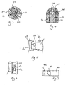
- a breakable pivot joint 10 shown in Figures 1 to 7 comprises two generally tubular joint parts 12 and 14 to which are connected, when in use, two respective ends 13 and 15 of tent-frame rib or bar sections. These sections may be tubular and made of aluminium, and are connected and secured to their associated joint parts 12 and 14 by a combination of a tight fit of respective ends of the rib or bar sections within the tubular parts and by screws through screw holes 16 and 18 and corresponding holes in the ends 13 and 15. The location of such holes in the rib or bar sections, and other holes (not shown) at their other ends can be used to ensure that further joints at those other ends are correctly oriented in relation to the illustrated joint to facilitate folding-up of the assembly.
- the parts 12 and 14 have respective tubular portions 12 a and 14 a . These have respective axes at about 140° to one another when they are in their relative open position as shown in Figure 1 .
- the joint parts 10 and 12 are each also provided with a hook-like clip 20 from which may be suspended sheeting material of a tent.
- the two joint parts 12 and 14 are pivotablly connected together by means of a pivot 22 which has a transverse turning axis offset from the axes of the tubular portions 12 a and 14 a .
- the joint part 12 has a female retaining portion or mouth portion 24 which opens towards the joint part 14 as shown in Figure 2 .
- the joint part 14 has a corresponding end portion 26 or male retaining portion which is received in the mouth portion 24 of the joint part 12.
- a locking member in the form of a slider 28 has a thumb-pad 30, extending around the outside of the end portion 26 of the joint part 14, and an inner serrated portion 32 which is immediately adjacent to the said end portion or male retaining portion 26. Corresponding serrations on the said end portion or male portion 26 engage the serrations of the slider 28.
- the said end portion or male portion 26 is so dimensioned and positioned in relation to the pivot 22 and the mouth portion 24 that a gap 34 is present between the mouth portion 24 and the said end portion 26 on the pivot side of the joint 10. Furthermore, a lower portion 36 which extends from and is integrally moulded with the slider 28 is urged towards the part 12 by a helical compression spring 38 provided in a spring cavity 40 of the joint part 14. As a result, parts 12 and 14 may be opened further until the gap 34 is closed and the mouth portion 24 no longer abuts the slider 28. The slider 28 may now be pulled outwardly from the mouth portion 24 against the restoring force of the compression spring 38. This enables the whole joint 10 now to be folded by pivoting the joint parts 12 and 14 relative to one another about the pivot 22 until the end portion 26 is entirely clear of the mouth portion 24.
- a catch 42 is provided on the slider 28.
- the catch 42 comprises a thumb-engageable part 44 on the outside of the slider 28 and an abutment portion 46 on the inside of the slider 28.
- the parts 44 and 46 of the catch 42 are connected together by a neck portion 48.
- the neck portion 48 extends through a slot 50 provided in the slider 28. This slot has a widened end portion 52 to facilitate insertion of the abutment portion 46 through the slot 50. This slot is shown most clearly in Figure 6 .
- That part of the end portion 26 which is underneath the slider 28 is shown most clearly in Figure 5 . It is formed with a recess 54 engaged by the abutment portion 46 of the catch 42 when the latter is in its locking position and the slider 28 is in its retracted position. It can be seen in this position that an abutment surface 56 on one side of the recess 54 abuts the abutment portion 46 of the catch 42.
- the end portion 26 is provided with a slanting surface 58 which meets the abutment surface 56.
- the abutment portion 46 of the catch 42 is also provided with slanting surface 60.
- Movement of the catch 42 in the other direction will now bring the abutment portion 46 thereof into position within the recess 54 to hold the slider 28 in its retracted position until the user engages the thumb-engageable part 44 of the catch 22 with his or her thumb to move the catch back to its unlocking position.
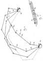
- a canopy shown in Figures 8 and 9 comprises a frame 80 comprising a plurality of joints 10, each of which has the construction illustrated and described with reference to Figures 1 to 7 . These joints 10 interconnect a series of rod sections 82 to form a series of arches spanning two spaced-apart support hubs 84 and 86. The canopy cover is attached by loops (not shown) to the hooks 20 of the joints 10.
- the joints are unlocked in the manner described herein so that the canopy frame can be folded-up substantially as shown in Figure 9 .
- the catch 42 of each joint 10 is shifted to its locking position while the slider 28 is in its retracted position. This retains the slider 28 in its retracted position. The catch 42 is shifted back into its unlocking position when it is desired to re-erect the canopy.
- the locking slider 28 may be arranged on the mouth portion 24, on the inside thereof, instead of on the said end portion 26.
- the tubular portions 12 a and 14 a of the parts 12 and 14 may have respective axes which are at a different angle to the one illustrated, or indeed they may be co-linear.
Description
- The present invention relates to a breakable joint as specified in the preamble of Claim 1, namely a joint comprising two parts which are pivotably connected to one another so that they can be moved relative to one another about the pivot from a folded position to an open position, in which an end portion of one of the parts is received in a mouth portion of the other of the parts, and a slidable locking member arranged on or constituted by the said mouth portion or the said end portion, the locking member being slidable in a direction which is transverse of the pivot axis from a retracted position, in which it permits the said end portion to be received by the mouth portion, to a forward position, in which, with the said end portion located in the mouth portion, it inhibits subsequent movement of the two parts about the pivot into the folded position until the locking member is retracted, the locking member being urged by resilient means into its forward position so that as the said two parts are moved about the pivot from the folded position to the open position, the locking member initially abuts the mouth portion or the end portion so that it is moved relative to that portion towards its retracted position until the said two parts reach their open position, whereupon the locking member snaps into its forward position under the action of the resilient means. Such a breakable joint is known eg from any of
EP-A-0 684 355 orEP-A-0 704 586 orUS-A-4 750 509 . - Preferably, the locking member is arranged on the said end portion.
- Such a joint is disclosed in co-pending European Patent Application
EP-A-1 310 616 in the name of Fox Design International Limited. In that context, the joint is used to join sections of a tent frame together, although it will be appreciated that the joint may be used in other applications where two elongate sections are folded together for storage, and opened outwardly for use, for example in various kinds of stands and supports. - One problem encountered with such a joint especially but not exclusively when it is used in the frame of a tent is that during dismantling after the joint has been broken, it may accidentally be locked in the open position before the dismantling procedure has been completed.
- An aim of the present invention is to obviate this disadvantage.
- Accordingly, the present invention provides a joint having the features set out in the opening paragraph of the present specification in which a selectively operable catch is provided on the joint to enable the locking member to be held in its retracted position, against the force of the resilient means, when it is desired to avoid accidental locking of the said two parts in their open position.
- The catch may be so constructed that it is slidable between a locking position and a non-locking position.
- This can be effected most readily if the catch is slidable in a direction which is generally parallel to the pivot axis.
- The catch may be provided with a thumb-engageable portion on the outside of the locking member, and an abutment portion on the inside of the locking member, there being a further abutment portion on the said end portion which engages the abutment portion of the catch when the latter is in its locking position and the locking member is in its retracted position.
- A slanting portion may be provided on the catch and/or on the said end portion to urge the catch into its non-locking position when the locking member is moved from its forward position to its retracted position.
- The present invention extends to a tent or canopy having a frame which is collapsible and erectable by means of at least one joint made in accordance with the present invention.
- An example of a joint and of a tent or canopy made in accordance with the present invention will now be described with reference to the accompanying drawings, in which:
- Figure 1
- shows a side view of a joint embodying the present invention;
- Figure 2
- shows a part axial sectional view of the device shown in
Figure 1 ; - Figure 3
- shows a cross-sectional view of the device shown in
Figure 1 taken in the plane indicated by the line III-III shown therein; - Figure 4
- shows a cross-sectional view of the joint shown in
Figure 1 taken in the plane indicated by the line IV-IV thereof; - Figure 5
- shows a view from above of a portion of the joint shown in
Figure 1 ; - Figure 6
- shows a view from above of another portion of the joint shown in
Figure 1 ; - Figure 7
- shows an underneath view of a portion of the joint shown in
Figure 1 ; - Figure 8
- shows a canopy frame incorporating a plurality of joints each as shown in
Figures 1 to 7 , and - Figure 9
- shows the frame of
Figure 8 in a collapsed condition. - A
breakable pivot joint 10 shown inFigures 1 to 7 comprises two generally tubularjoint parts respective ends joint parts screw holes ends parts Figure 1 . Thejoint parts like clip 20 from which may be suspended sheeting material of a tent. - The two
joint parts pivot 22 which has a transverse turning axis offset from the axes of the tubular portions 12a and 14a. - The
joint part 12 has a female retaining portion ormouth portion 24 which opens towards thejoint part 14 as shown inFigure 2 . Thejoint part 14 has acorresponding end portion 26 or male retaining portion which is received in themouth portion 24 of thejoint part 12. A locking member in the form of aslider 28 has a thumb-pad 30, extending around the outside of theend portion 26 of thejoint part 14, and an innerserrated portion 32 which is immediately adjacent to the said end portion ormale retaining portion 26. Corresponding serrations on the said end portion ormale portion 26 engage the serrations of theslider 28. The flexure of the rib or bar sections held by thejoint 10 when the latter is in use, as a result of the inward pull of tent material, tends to break thepivot joint 10 to pivot the saidend portion 26 out of engagement with the mouth orfemale retaining portion 24. However, the abutment of theinner portion 32 againt the roof of themouth portion 24 prevents this from happening, unless and until the user operates theslider 28 to disengage theportions - To enable such disengagement to happen, the said end portion or
male portion 26 is so dimensioned and positioned in relation to thepivot 22 and themouth portion 24 that agap 34 is present between themouth portion 24 and the saidend portion 26 on the pivot side of thejoint 10. Furthermore, alower portion 36 which extends from and is integrally moulded with theslider 28 is urged towards thepart 12 by ahelical compression spring 38 provided in aspring cavity 40 of thejoint part 14. As a result,parts gap 34 is closed and themouth portion 24 no longer abuts theslider 28. Theslider 28 may now be pulled outwardly from themouth portion 24 against the restoring force of thecompression spring 38. This enables thewhole joint 10 now to be folded by pivoting thejoint parts pivot 22 until theend portion 26 is entirely clear of themouth portion 24. - A
catch 42 is provided on theslider 28. Thecatch 42 comprises a thumb-engageable part 44 on the outside of theslider 28 and anabutment portion 46 on the inside of theslider 28. Theparts catch 42 are connected together by aneck portion 48. Theneck portion 48 extends through a slot 50 provided in theslider 28. This slot has a widened end portion 52 to facilitate insertion of theabutment portion 46 through the slot 50. This slot is shown most clearly inFigure 6 . - That part of the
end portion 26 which is underneath theslider 28 is shown most clearly inFigure 5 . It is formed with arecess 54 engaged by theabutment portion 46 of thecatch 42 when the latter is in its locking position and theslider 28 is in its retracted position. It can be seen in this position that anabutment surface 56 on one side of therecess 54 abuts theabutment portion 46 of thecatch 42. - The
end portion 26 is provided with aslanting surface 58 which meets theabutment surface 56. Theabutment portion 46 of thecatch 42 is also provided withslanting surface 60. In the event that thecatch 42 is in its locking position with theslider 28 in its forward position, retraction of theslider 28 causes theslanting surfaces slider 28 to cause thecatch 42 to slide into its unlocking position as theneck 48 thereof moves within the slot 50. Movement of thecatch 42 in the other direction will now bring theabutment portion 46 thereof into position within therecess 54 to hold theslider 28 in its retracted position until the user engages the thumb-engageable part 44 of thecatch 22 with his or her thumb to move the catch back to its unlocking position. - A canopy shown in
Figures 8 and 9 comprises aframe 80 comprising a plurality ofjoints 10, each of which has the construction illustrated and described with reference toFigures 1 to 7 . Thesejoints 10 interconnect a series ofrod sections 82 to form a series of arches spanning two spaced-apart support hubs hooks 20 of thejoints 10. - When the canopy is collapsed, the joints are unlocked in the manner described herein so that the canopy frame can be folded-up substantially as shown in
Figure 9 . To ensure that none of the joints are accidentally opened and locked in their open position while the canopy is being collapsed, thecatch 42 of each joint 10 is shifted to its locking position while theslider 28 is in its retracted position. This retains theslider 28 in its retracted position. Thecatch 42 is shifted back into its unlocking position when it is desired to re-erect the canopy. - Numerous variations and modifications to the illustrated joint and canopy can be made if without taking the resulting constructions outside the scope of the present invention as claimed below. For example, the locking
slider 28 may be arranged on themouth portion 24, on the inside thereof, instead of on the saidend portion 26. The tubular portions 12a and 14a of theparts - What has been shown as a canopy in
Figures 8 and 9 can be constructed rather as a tent with a single central hub raised above the ground by a series of legs, each of which includes a breakable joint as shown inFigures 1 to 7 . - It will be appreciated that in the event that a joint 10 breaks, it can be readily replaced by unscrewing the screws at the screw-
holes
Claims (7)
- A breakable joint (10) comprising two parts (12 and 14) which are pivotably connected to one another so that they can be moved relative to one another about the pivot (22) from a folded position to an open position, in which an end portion (26) of one of the parts (14) is received in a mouth portion (24) of the other of the parts (12), and a slidable locking member (28) arranged on or constituted by the said mouth portion (24) or the said end portion (26), the locking member (28) being slidable in a direction which is transverse of the pivot axis from a retracted position, in which it permits the said end portion (26) to be received by the mouth portion (24), to a forward position, in which, with the said end portion (26) located in the mouth portion (24), it inhibits subsequent movement of the two parts (12 and 14) about the pivot (22) into the folded position until the locking member (28) is retracted, the locking member (28) being urged by resilient means (38) into its forward position so that as the said two parts (12 and 14) are moved about the pivot (22) from the folded position to the open position, the locking member (28) initially abuts the mouth portion (24) or the end portion (26) so that it is moved relative to that portion towards its retracted position until the said two parts (12 and 14) reach their open position, whereupon the locking member (28) snaps into its forward position under the action of the resilient means (38), characterised in that a selectively operable catch (42) is provided on the joint (10) to enable the locking member (28) to be held in its retracted position, against the force of the resilient means (38), when it is desired to avoid accidental locking of the said two parts (12 and 14) in their open position.
- A breakable joint according to claim 1, characterised in that the locking member (28) is arranged on the said end portion (26).
- A breakable joint according to claim 1 or claim 2, characterised in that the catch (42) is so constructed that it is slidable between a locking position and a non-locking position.
- A breakable joint according to claim 3, characterised in that the catch (42) is slidable in a direction which is generally parallel to the pivot axis.
- A breakable joint according to any preceding claim, characterised in that the catch (42) is provided with a thumb-engageable portion (44) on the outside of the locking member (28), and an abutment portion (46) on the inside of the locking member (28), there being a further abutment portion (56) on the said end portion (26) which engages the abutment portion (46) of the catch (42) when the latter is in its locking position and the locking member (28) is in its retracted position.
- A breakable joint according to any preceding claim, characterised in that a slanting portion is provided on the catch (42) and/or on the said end portion (26) to urge the catch (42) into its non-locking position when the locking member (28) is moved from its forward position to its retracted position.
- A tent or canopy having a frame (80) which is collapsible and erectable by means of at least one joint (10) as claimed in any preceding claim.
Applications Claiming Priority (2)
| Application Number | Priority Date | Filing Date | Title |
|---|---|---|---|
| GB0227001 | 2002-11-19 | ||
| GB0227001A GB0227001D0 (en) | 2002-11-19 | 2002-11-19 | A joint |
Publications (2)
| Publication Number | Publication Date |
|---|---|
| EP1422360A1 EP1422360A1 (en) | 2004-05-26 |
| EP1422360B1 true EP1422360B1 (en) | 2009-03-11 |
Family
ID=9948137
Family Applications (1)
| Application Number | Title | Priority Date | Filing Date |
|---|---|---|---|
| EP20030257288 Expired - Fee Related EP1422360B1 (en) | 2002-11-19 | 2003-11-19 | A joint |
Country Status (3)
| Country | Link |
|---|---|
| EP (1) | EP1422360B1 (en) |
| DE (1) | DE60326530D1 (en) |
| GB (1) | GB0227001D0 (en) |
Families Citing this family (1)
| Publication number | Priority date | Publication date | Assignee | Title |
|---|---|---|---|---|
| ITMI20050432U1 (en) * | 2005-12-09 | 2007-06-10 | Zingerlemetal S P A | CURTAIN WITH ARTICULATED STRUCTURE AND MOBILE WITH SAFETY DEVICE FOR CLOSING |
Family Cites Families (3)
| Publication number | Priority date | Publication date | Assignee | Title |
|---|---|---|---|---|
| US4750509A (en) * | 1985-11-25 | 1988-06-14 | Kim Soon Tae | Folding device of a tent-framework |
| GB9410539D0 (en) * | 1994-05-26 | 1994-07-13 | Fox Design Int | A tent or canopy frame device |
| NL9402173A (en) * | 1994-09-30 | 1996-05-01 | F J B Praktiek | Tent frame and hinge for this. |
-
2002
- 2002-11-19 GB GB0227001A patent/GB0227001D0/en not_active Ceased
-
2003
- 2003-11-19 DE DE60326530T patent/DE60326530D1/en not_active Expired - Fee Related
- 2003-11-19 EP EP20030257288 patent/EP1422360B1/en not_active Expired - Fee Related
Also Published As
| Publication number | Publication date |
|---|---|
| EP1422360A1 (en) | 2004-05-26 |
| GB0227001D0 (en) | 2002-12-24 |
| DE60326530D1 (en) | 2009-04-23 |
Similar Documents
| Publication | Publication Date | Title |
|---|---|---|
| US8910648B2 (en) | Connector device for a foldable tent | |
| US6565069B2 (en) | Handrail gate, hinge coupling and lock | |
| US5666986A (en) | Tent frame device | |
| US20190003254A1 (en) | Extendable / retractable ladder | |
| US7584763B2 (en) | Collapsible frame for portable shelter | |
| US5495915A (en) | Collapsible ladder | |
| US7669815B2 (en) | Dual release locking system for a sign supporting stand | |
| US9668554B2 (en) | Umbrella having an anti-inversion mechanism | |
| KR102321528B1 (en) | Umbrella having improved shaft and rib assembly | |
| EP1422360B1 (en) | A joint | |
| EP0657614A1 (en) | Convertible ladder assembly | |
| CN114466965A (en) | Human-shaped ladder pivot and locking mechanism | |
| JP2019060080A (en) | Telescopic locking mechanism of telescopic leg device in ladder available as stepladder | |
| WO2016100294A1 (en) | Collapsible canopy | |
| WO2023185729A1 (en) | Tent having reinforcement mechanism | |
| CN112627628A (en) | Pop-up canopy | |
| EP1310616A2 (en) | A tent or canopy frame | |
| WO2011004191A1 (en) | Ladder with guard rail | |
| CA2876898A1 (en) | Extendable/retractable ladder | |
| AU2007229411B2 (en) | A Stabilizer for a Ladder | |
| EP0704586A1 (en) | Tent frame and hinge | |
| CN109577743B (en) | Refrigerator handle and refrigerator | |
| CA2353222C (en) | Handrail gate, hinge coupling and lock | |
| WO2003101803A1 (en) | Umbrella attachment | |
| CN112656100A (en) | Umbrella with external stay rod frame |
Legal Events
| Date | Code | Title | Description |
|---|---|---|---|
| PUAI | Public reference made under article 153(3) epc to a published international application that has entered the european phase |
Free format text: ORIGINAL CODE: 0009012 |
|
| AK | Designated contracting states |
Kind code of ref document: A1 Designated state(s): AT BE BG CH CY CZ DE DK EE ES FI FR GB GR HU IE IT LI LU MC NL PT RO SE SI SK TR |
|
| AX | Request for extension of the european patent |
Extension state: AL LT LV MK |
|
| 17P | Request for examination filed |
Effective date: 20041126 |
|
| AKX | Designation fees paid |
Designated state(s): BE DE FR GB IT NL |
|
| GRAP | Despatch of communication of intention to grant a patent |
Free format text: ORIGINAL CODE: EPIDOSNIGR1 |
|
| GRAS | Grant fee paid |
Free format text: ORIGINAL CODE: EPIDOSNIGR3 |
|
| GRAA | (expected) grant |
Free format text: ORIGINAL CODE: 0009210 |
|
| AK | Designated contracting states |
Kind code of ref document: B1 Designated state(s): BE DE FR GB IT NL |
|
| REG | Reference to a national code |
Ref country code: GB Ref legal event code: FG4D |
|
| REF | Corresponds to: |
Ref document number: 60326530 Country of ref document: DE Date of ref document: 20090423 Kind code of ref document: P |
|
| PLBE | No opposition filed within time limit |
Free format text: ORIGINAL CODE: 0009261 |
|
| STAA | Information on the status of an ep patent application or granted ep patent |
Free format text: STATUS: NO OPPOSITION FILED WITHIN TIME LIMIT |
|
| 26N | No opposition filed |
Effective date: 20091214 |
|
| BERE | Be: lapsed |
Owner name: FOX INTERNATIONAL GROUP LTD Effective date: 20091130 |
|
| REG | Reference to a national code |
Ref country code: NL Ref legal event code: V1 Effective date: 20100601 |
|
| GBPC | Gb: european patent ceased through non-payment of renewal fee |
Effective date: 20091119 |
|
| REG | Reference to a national code |
Ref country code: FR Ref legal event code: ST Effective date: 20100730 |
|
| PG25 | Lapsed in a contracting state [announced via postgrant information from national office to epo] |
Ref country code: NL Free format text: LAPSE BECAUSE OF NON-PAYMENT OF DUE FEES Effective date: 20100601 Ref country code: FR Free format text: LAPSE BECAUSE OF NON-PAYMENT OF DUE FEES Effective date: 20091130 Ref country code: BE Free format text: LAPSE BECAUSE OF NON-PAYMENT OF DUE FEES Effective date: 20091130 |
|
| PG25 | Lapsed in a contracting state [announced via postgrant information from national office to epo] |
Ref country code: DE Free format text: LAPSE BECAUSE OF NON-PAYMENT OF DUE FEES Effective date: 20100601 |
|
| PG25 | Lapsed in a contracting state [announced via postgrant information from national office to epo] |
Ref country code: GB Free format text: LAPSE BECAUSE OF NON-PAYMENT OF DUE FEES Effective date: 20091119 |
|
| PG25 | Lapsed in a contracting state [announced via postgrant information from national office to epo] |
Ref country code: IT Free format text: LAPSE BECAUSE OF NON-PAYMENT OF DUE FEES Effective date: 20091119 |