EP0704586A1 - Tent frame and hinge - Google Patents
Tent frame and hinge Download PDFInfo
- Publication number
- EP0704586A1 EP0704586A1 EP95306953A EP95306953A EP0704586A1 EP 0704586 A1 EP0704586 A1 EP 0704586A1 EP 95306953 A EP95306953 A EP 95306953A EP 95306953 A EP95306953 A EP 95306953A EP 0704586 A1 EP0704586 A1 EP 0704586A1
- Authority
- EP
- European Patent Office
- Prior art keywords
- hinge
- tent
- locking
- pole
- frame
- Prior art date
- Legal status (The legal status is an assumption and is not a legal conclusion. Google has not performed a legal analysis and makes no representation as to the accuracy of the status listed.)
- Withdrawn
Links
Images


Classifications
-
- E—FIXED CONSTRUCTIONS
- E04—BUILDING
- E04H—BUILDINGS OR LIKE STRUCTURES FOR PARTICULAR PURPOSES; SWIMMING OR SPLASH BATHS OR POOLS; MASTS; FENCING; TENTS OR CANOPIES, IN GENERAL
- E04H15/00—Tents or canopies, in general
- E04H15/32—Parts, components, construction details, accessories, interior equipment, specially adapted for tents, e.g. guy-line equipment, skirts, thresholds
- E04H15/34—Supporting means, e.g. frames
- E04H15/44—Supporting means, e.g. frames collapsible, e.g. breakdown type
- E04H15/48—Supporting means, e.g. frames collapsible, e.g. breakdown type foldable, i.e. having pivoted or hinged means
-
- E—FIXED CONSTRUCTIONS
- E04—BUILDING
- E04H—BUILDINGS OR LIKE STRUCTURES FOR PARTICULAR PURPOSES; SWIMMING OR SPLASH BATHS OR POOLS; MASTS; FENCING; TENTS OR CANOPIES, IN GENERAL
- E04H15/00—Tents or canopies, in general
- E04H15/32—Parts, components, construction details, accessories, interior equipment, specially adapted for tents, e.g. guy-line equipment, skirts, thresholds
- E04H15/34—Supporting means, e.g. frames
- E04H15/36—Supporting means, e.g. frames arch-shaped type
- E04H15/40—Supporting means, e.g. frames arch-shaped type flexible
Definitions
- the present invention concerns a tent-frame fitted with collapsible poles preferably made from flexible sections, individually attached to hinges [having a position in which they are securely immobile] ("locked"), each hinge being provided with a first an a second hinge-element each of which is attached to the corresponding pole-section via a knuckle-pin and in addition provided with a locking-device in the form of a spring-loaded first locking-device attached to the first hinge-element in such a way that it can move with it towards a locked position, together with a second locking-device in the form of a second hinge-element that enables the first hinge-element to engage with the pole-sections at any desired angle.
- FIG. 409 An example of a tent-frame of this kind is furnished in U.S. patent no. 4,750,509.
- This patent shows a dome-tent having a tent-frame with no detached parts that can be put up quite simply by pushing upwards a central boss-element to which the poles are fastened with hinges.
- the locking-device in the hinges on the collapsible poles includes a sleeve as a first lock-component and a continuation-piece of the knuckle of the hinge as the second.
- the sleeve In order to lock each hinge the sleeve has to work against a spring. In so doing it pushes the continuation-piece out of the way, whereupon the pole-sections can be moved along their length, enabling them to be locked into position by the pushing back of the sleeve over the continuation-piece.
- the [present] invention now seeks to define a tent-frame of the kind defined in the preamble that has a simpler construction, that is reliable in operation and that is easy to put up.
- the tent-frame described in the invention is characterised by the fact that the first lock-component is a locking-pin forming part of the first hinge-element, and that the second lock-component is a specially shaped locking-recess in the second hinge-element into which the locking-pin fits in its locked position.
- the form of construction used in the invention also makes it easy for the locking-device to operate automatically when the pole-sections have been brought to the desired angle, for example by extending the poles, as a result of which it is no longer necessary to manipulate each hinge separately to effect the locking.
- the second hinge-element can be provided with a take-up surface extending from the recess in the hingeing-direction against which the spring-loaded locking-pin rests when the hinge is in the unlocked position.
- the locking-pin will move the hinges into the upright position by the action of the poles along the take-up surface up to the locking-recess, and these [poles] will then be pushed automatically into the locking-recess under the action of the spring. In this way the tent can be set up in the locked position with a single movement.
- first and second hinge-elements In order to keep down the number of components and thus to simplify the tent-frame as a whole it is best for the first and second hinge-elements to have the same shape.
- poles to be attached at their upper ends by further hinges to a central boss-element and for these hinges to be fitted with a further locking-device that locks the poles in relation to the boss-element when the tent is in the erect position.
- a further advantage of the invention is that by attaching the ends of the poles to a clamping-device of some kind fixed to the ground-sheet of the tent the position of the lower end of each of the poles can be adjusted either inwards or outwards.
- each pole By means of this adjustable attachment of each pole to its corresponding clamping-device it becomes possible for the tent-cloth to be stretched until it is satisfactorily taut. This adjustment can also be made if the spring-loaded collapsible poles are exerting too much or too little pressure on the cloth, or if the poles are locked in position with the central boss-element, thereby making it impossible for this linkage to exert any pressure on the cloth.
- the invention also embraces the hinge used in the tent-frame described herein and the tent to be used with that tent-frame.
- FIG. 1 and 2 show a tent that consists of an outer tent-cloth (1), an inner tent-cloth (3) joined to it by spacers (2), and a tent-frame (4) that keeps tent-cloths (1) and (3) in the desired position when the tent is up.
- the tent-frame (4) consists in this example of four poles (5) that are attached at their upper ends to a central boss-element (6) and at their lower ends to a clamping-device (7) that is in turn attached to the inner tent-cloth 3, of which the ground-sheet (9) forms part, by means of a corner joint (8).
- tent-cloths 1 and 3 may be made in quite different shapes, and the tent-frame 4 too may be implemented in a quite different way. So tent-cloths 1 and 3 may be rectangualar in shape rather than strictly square, and the ground-plan of the tent may also be triangular or even polygonal or circular. The number of poles 5 may be varied in a similar way to match the shape.
- the material of which the tent-cloths 1 and 3 are made is likewise unrestricted, though in this example a lightweight fabric such as cotton, nylon, or some other artificial fibre, has been [assumed as the] preferred material for tent-cloths 1 and 3.
- each pole 5 consists of a number (in this case three) of pole-sections (10) of a flexible lightweight construction, which are thus capable of adopting a curved conformation and thereby able to transmit pressure to the tent-cloths 1 and 3 so as to keep them taut.
- Contiguous pole-sections 10 within a given pole 5 are joined by a hinge (11), which allows the poles 5 to be folded up [or "collapsed"], as the central portion of Figure 2 shows by means of dot-and-dash lines.
- adjoining hinges 11 are hinged together in each case so that the poles 5 can be folded up in a zigzag arrangement.
- each pole 5 is attached to the central boss-element 6 by a hinge (12) so that when the tent-frame 4 is folded up a hingeing-movement is possible in this case too. All components of the tent-frame 4 in theory remain joined together when the tent is folded up, which makes it impossible for components to become detached and lost, also making it very easy to put the tent up, at least when tent-cloths 1 and 3 remain partially attached to the tent-frame 4.
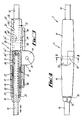
- FIGS 3, 4 and 5 show a particular form of the hinge 11 which incorporates a locking-device (15).
- hinge 11 consists of a first hinge-element (16) and a second hinge-element (17), it being clearly visible that these hinge-elements 16 and 17 are of identical shape, with the consequence that the number of different components in the tent-frame 4 is much smaller [than it would otherwise have been].
- the first and second hinge-elements 16 and 17 are each attached via a hinge pin (18) mounted off-centre in an extension (19) the effect of which is to allow a hingeing-movement of hinge-elements 16 and 17 out of the locked position in one hingeing-direction only.
- the hinge pin is incorporated in a bisected portion (20) of each of the hinge-elements 16 and 17, by which means the identically shaped hinge-elements 16 and 17 are able to fit together firmly.
- Each hinge-element 16 or 17 has a hole (21) drilled in it to accommodate the corresponding pole-section 10, the hinge-element 16 or 17 being joined [to its] corresponding [pole-section] by a pole-section end-piece (22 and 23, respectively) in this case.
- the hole 21 of each hinge-element 16 or 17 is drilled in stepped fashion with a first part (24) of relatively small diameter at the end adjoining the pole-section 10 and a second part (25) of relatively large diameter at the end facing the other hinge-element, 17 or 16.
- This second part 25 of the drilled hole 21 is also provided with a key-seating [(26)] over part of its length starting at the end facing the other hinge-element, 17 or 16.
- the pole-section end-piece 23 for the second hinge-element 17 is also made in a stepped fashion with a relatively narrow part (27) that fits into the first part 24 of the drilled hole and a relatively wide part (28) that fits into the second part 25 of the drilled hole but which is somewhat shorter than it so as to leave a certain length of that second part 25 [of the drilled hole] unoccupied.
- a fixing-key (29) specially shaped to fit the end-piece 23 fits into the key-seating 26 in the second part 25 of the drilled hole 21 in the second hinge-element 17.
- the pole-section end-piece 23 is in turn provided with a longitudinal drilled hole (30), which is open at the end next to the narrower portion 27 of the end-piece 23 and closed at the opposite end so that the corresponding pole-section 10 slots into the longitudinal drilled hole 30.
- the closed end-wall of the end-piece 23 is provided with a positioning-device in the form of a transverse rib (30') that fits into another positioning-device on the pole-section 10 in the form of a transverse groove (10').
- pole-section 10 To assemble the pole-section 10 with its corresponding second hinge-element 17 the end-piece 23 from the (larger-diameter) second part 25 of the drilled hole 21 is inserted and the pole-section 10 from the opposite end [likewise inserted], pole-section 10 for preference being then glued to the end-piece [22?], and end-piece 23 being similarly glued into the second hinge-element 17 [*03] .
- the pole-section 10 is always offset at a pre-determined angle relative to the second hinge-element 17, the hinge-elements at the opposite ends of each pole-section 10 being thus positioned at the desired angle in consequence.
- pole-section 10 can be mounted at two angular offsets over 180° apart, so that the hinges 11 can be fastened for folding up the poles 5 into a zigzag arrangement, it being a necessary requirement that the pole-sections should be relatively positioned at such an angle for folding up of the poles in zigzag fashion to be possible at all.
- the pole-section end-piece 22 that goes with the first hinge-element 16 is made longer than the pole-section end-piece 23 and is so mounted that it can be displaced inside the first hinge-element 16, to enable it to function as the locking-device 15 of the hinge 11.
- the end of the end-piece 22 facing the second hinge-element 17 is made to serve as a locking-pin (31) that can be moved between a locked position, as shown in Figure 3, in which it (the locking-pin 31) is positioned in that portion of the drilled hole 21 in the hinge-elements 16 and 17 that is formed by the bisected parts 20 of the two hinge-elements 16 and 17, and an unlocked position in which it (locking-pin 31) is withdrawn into the first hinge-element 16.
- the unlocked position of locking-pin 31 is determined by [the fixed position of] the end of the key-seating 26 against which the fixing-key 29 on the pole-section end-piece 22 abuts.
- the opposite locking-position is flanked by projections (32) at that end of the locking-pin 31 that is turned away from end-piece 22.
- a helical compression-spring (33) fitted round end-piece 22 exerts a force on locking-pin 31 in the direction of the locked position, spring 33 being confined by on one side a shoulder formed by the lip at the transition between the first and second parts 24 and 25 of the drilled hole in the first hinge-element 16 and on the other side by a shoulder formed by the lip at the point of transition from the narrower portion 27 [of end-piece 22] and the locking-pin 31 [forming part of] end-piece 22.
- the end of it is provided with two inward-flexing legs (34), instead of the projections 32, which fit round the end of longitudinal hole 30 that receives the pole-section 10.
- legs 34 can be bent inwards so far that the projections 32 lie within the diameter of the first part 24 of the drilled hole. In this way it is possible to mount the end-piece 22 in the first hinge-element 16 by inserting it (the end-piece) from the end of drilled hole 21 so as just to reach the second (larger) part 25 of the drilled hole 21 without pole-section 10 penetrating the longitudinal drilled hole 30 in the end-piece 22. When this is done it is possible for the legs 34 to bend inwards so as to allow this end of the end-piece 22, together with the projections 32, to be passed right through the drilled hole 21. After the passage of the first part 24 of the drilled hole between the projections 32 the legs 34 spring back out again.
- the locking-pin 31 and with it the whole locking-device 15 can now be released by pulling the pole-section 10 out of the first hinge-element 16 as far as the stop provided by the locating-pin 31, by which means locking-pin 31 moves out of the locking-recess formed by the drilled hole 21 in the second hinge-element 17, and the hinge-elements 16 and 17 can be rotated relative to each other round the knuckle-pin 18.
- the locking-pin 31 (*04) comes to rest with its free end against the take-up surface (35) formed by the extension 19 of the second hinge-element 17, extending from the drilled hole 21 in the direction of hingeing.
- This take-up surface 35 terminates next to drilled hole 21 at a greater distance from the knuckle-pin 18 than [when it is] further away [from the hole], as a result of which hinge 11 remains in the folded-open position and is not displaced by the pressure of the helical compression-spring 33 on the locking-pin 31 to its extreme position.
- the tent-frame 4 is thus stable when folded up in this position.
- the take-up surface 35 ensures that when the hinge 11 is rotated to its extreme position the locking-pin [31] is automatically inserted in the drilled hole 21 that functions as a locking-recess and that it is automatically pressed into the locking-recess by the action of the helical compression-spring 33, by which means an automatic locking-action is triggered at the extreme position of the hinge and therefore at the extreme position of the pole 5, thus rendering it unnecessary for any separate [manual] locking-action to be taken to put the tent up.
- hinge 11 is very simple, having only five component parts, of which two are identical. Most of the components can be made of plastic using injection-moulding equipment.
- FIGs 3 and 4 show in addition that a bracket (36) is provided on every one of the hinge-elements 16 and 17 on to which a noose (37) (see Figure 2) of the tent-cloth 1 can be hooked [*05] in order to attach the tent-cloth at every spot where there is a hinge 11 to the tent-frame 4.
- the tent-cloth 1 may of course still be joined to the poles at other places, while it is even possible to dispose the tent-frame 4 and the outer tent-cloth 1 in such a way that tent-frame 4 has to be placed inside the outer tent-cloth 1.
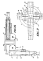
- FIGs 6 and 7 show the central boss-element 6 in detail, together with the poles 5 that are hinged on to it.
- This attachment is effected by means of the hinges 12, which are implemented with the first hinge-element 16 incorporating the locking-device 15, as already described.
- the locking-recess in the central boss-element 6 takes the form of a bisected hole (38) which, with the hinges 12 in the locked position and in conjunction with the bisected hole 21 of the first hinge-element 16, forms a hole [that is fully circular in cross-section) into which the locking-pin 31 can fit.
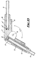
- Figure 8 shows an alternative version of a hinge 11 between two pole-sections 10, in which the pole-sections when in the locked position do not lie end to end but are disposed at an angle ( ⁇ ) of 130° apart [*06] .
- the first hinge-element 16 with the pole-section end-piece 22 and the locking-pin 31 can still be retained, though the second hinge-element 17 is in this case a special component of a design different from that of the first hinge-element 16. Since the second hinge-element 17 is made differently the pole-section 10 can be glued directly into a hole (39) drilled in the second hinge-element 17, in which once again positioning-devices 30' and 10' are incorporated. A bisected hole (40) in the second hinge-element again forms the locking-recess for the locking-pin 31.
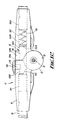
- Figure 9 shows the clamping-device 7 in detail with a toothed hobbing (41) to provide a number of supporting indentations (42) in which a knuckle-pin 18 of the hinge-element 17 can engage at the far end of the corresponding pole 5 so that the lower end of the pole 5 can be positioned.
- a toothed hobbing (41) to provide a number of supporting indentations (42) in which a knuckle-pin 18 of the hinge-element 17 can engage at the far end of the corresponding pole 5 so that the lower end of the pole 5 can be positioned.
- the tension of the tent-cloth 1 can be changed, by which means not only can a beautifully taut tent-cloth 1 be obtained in all kinds of weather (wet, dry, etc.), but situations in which the cloth is either too loose or too taut can be avoided.
- the invention is not confined to the particular examples described in the above text and illustrated in the diagrams, for within the overall framework of the invention variations of different kinds are possible.
- the knuckle-pin 18 of the hinges 11 and 12 may be replaced by a butt-hinge, and the hinge-elements 16 and 17 may be made in one piece.
- the pole-pieces[ sic ] 10 can likewise in theory be made wholly rigid [rather than flexible].
- the hinge-elements 16,17 define respectively a bore 101 and a bore 102 which are arranged in register with each other when the hinge 11 is in its locked position such that the bores 101 and 102 communicate with each other.
- the locking device further includes a locking pin 131 having a head 132A of larger diameter than the shank 132B thereof.
- the shank 132B extends from the bore 102 in the hinge-element 17 through to the bore 101 in the hinge-element 16.
- Urging means in the form of a spring 133 is arranged between the locking pin 131 and the pole section 10 inserted into the hinge-element 17. The spring 133 urges the locking pin 131 in the direction indicated by the arrow A in Fig. 11.
- the bore 102 is defined in three sections, the first section 102A holds the pole section 10 which is fixedly mounted therein.
- the second section 102B which is of narrower diameter than the first section 102A holds the spring 133.
- the second section 102B holds the head 132 of the locking pin 131.
- the third section 102C which is of narrower diameter than the second section 102B houses the shank 132B of the locking pin 131.
- the locking pin 131 includes a projection 134 which extends outwardly from the shank 132B to a position external of the hinge-element 16.
- a button 136 is provided on the projecting element 134, the purpose of which will be explained below.
- Cut out regions 138A,138B are defined respectively in the hinge-elements 16,17.
- the cut out region 138A,138B communicate with each other.
- the hinge is in the locked position as shown in Fig. 11, the bottom 136 and the projecting element 134 are held in the cut out 138A.
- the button 136 In order to move the hinge 11 to its unlocked position, the button 136 is moved in the direction opposite to the arrow A against the action of the spring 133; from the cut out region 138A to the region 138B. This moves the locking pin 131 out of engagement with the surfaces defining the bore 101 in the hinge-element 16. This enables the two hinge-elements 16,17 to be moved away from the locked position to the unlocked position.
- FIG. 12 there is shown a modification to the embodiment shown in Figs. 11 and 12, which is generally the same as the hinge 11 shown in Figs. 11 and 12, but differs in that the locking pin 131 is provided with a sloping surface 140 which enables the distance the locking pin 131 needs to be moved to disengage it from the hinge-element 16 thereby faciliating moving the hinge 11 to the unlocked position.
- a further embodiment which provides for automatic unlocking of the hinge element 16,17.
- the same features have been given the same reference numerals as those in Figs. 10 to 12.
- the bore 102 is a blind bore terminating at the end 103 of the third section 102C.
- the bore 101 of the hinge-element 16 terminates at the end 104 of the third section 101C.
- the section 102B is narrower than the section 102A, and, in turn, the section 102C is narrower than the section 102B.
- the diameters of the sections 101A,101B,101C decrease from section 101A to section 101C.
- the extension 19 of the hinge-element 16 defines an elongate aperture 18A for the hinge pin 18.
- the purpose of the elongate aperture 18A enables movement of the hinge-element 17 away from the hinge-element 16, by sliding the hinge-element 17 against the action of the spring 133, i.e. in the direction of the arrow B, over the pole section 10 housed within the hinge-element 17.
- the extension 19 is provided with a shoulder 19A against which a corner 17A of the hinge-element 17 engages when the hinge 11 is in the locking position, as shown in Figs. 13 and 14.
- the hinge 11 is held in the locked position when the tent is errected by the forces applied thereto by the pole-sections 10.
- the spring 133 pushing against the pole section 10 in the hinge element 17 pushes the hinge-element 17 towards the hinge-element 16 to further hold the hinge 11 in the locked position.
- the forces pushing against the pole-sections 10 are released, such that the only force pushing the hinge-element 17 against the hinge-element 16 is that of the spring 133.
- This force is not too great and the hinge-element 17 can be moved against the action of the spring 133 by applying a force in the direction of the arrow B, and when the corner 17A of the hinge-element 17 is moved beyond the shoulder 19A, the hinge-element 17 can be moved to the unlocked position.
- the locking-pin 131 is provided with a sloping surface 140 which allows the hinge-element 17 to be moved to the unlocked position when the corner 17A is moved passed the edge of the shoulder 19A.
- the locking-pin 131 is provided with a projection 142 which extends into the cut out region 138B.
- the purpose of the projection 142 is to prevent twisting of the hinge-element 17.
Landscapes
- Engineering & Computer Science (AREA)
- Architecture (AREA)
- Civil Engineering (AREA)
- Structural Engineering (AREA)
- Tents Or Canopies (AREA)
Abstract
A tent frame hinge (11) has first and second hinge portions (16,17) hinged at (18). A lock (31) is slidable to lock the hinge (as shown in the drawing) or to withdraw against the spring (25) to release the hinge.
Description
- The present invention concerns a tent-frame fitted with collapsible poles preferably made from flexible sections, individually attached to hinges [having a position in which they are securely immobile] ("locked"), each hinge being provided with a first an a second hinge-element each of which is attached to the corresponding pole-section via a knuckle-pin and in addition provided with a locking-device in the form of a spring-loaded first locking-device attached to the first hinge-element in such a way that it can move with it towards a locked position, together with a second locking-device in the form of a second hinge-element that enables the first hinge-element to engage with the pole-sections at any desired angle.
- An example of a tent-frame of this kind is furnished in U.S. patent no. 4,750,509. This patent shows a dome-tent having a tent-frame with no detached parts that can be put up quite simply by pushing upwards a central boss-element to which the poles are fastened with hinges. The locking-device in the hinges on the collapsible poles includes a sleeve as a first lock-component and a continuation-piece of the knuckle of the hinge as the second. In order to lock each hinge the sleeve has to work against a spring. In so doing it pushes the continuation-piece out of the way, whereupon the pole-sections can be moved along their length, enabling them to be locked into position by the pushing back of the sleeve over the continuation-piece.
- The [present] invention now seeks to define a tent-frame of the kind defined in the preamble that has a simpler construction, that is reliable in operation and that is easy to put up.
- For this purpose the tent-frame described in the invention is characterised by the fact that the first lock-component is a locking-pin forming part of the first hinge-element, and that the second lock-component is a specially shaped locking-recess in the second hinge-element into which the locking-pin fits in its locked position.
- The fact that the locking-pin and the locking-recess in the hinge-elements move inwards clearly reduces the risk of the whole locking-device failing to engage in the locked position for some external reason, and of it being knocked out of the locked position in some such way, thereby imperilling the stability of the tent. The form of construction used in the invention also makes it easy for the locking-device to operate automatically when the pole-sections have been brought to the desired angle, for example by extending the poles, as a result of which it is no longer necessary to manipulate each hinge separately to effect the locking. One possible application of this is that on the side facing the first hinge-element the second hinge-element can be provided with a take-up surface extending from the recess in the hingeing-direction against which the spring-loaded locking-pin rests when the hinge is in the unlocked position. When this is done the locking-pin will move the hinges into the upright position by the action of the poles along the take-up surface up to the locking-recess, and these [poles] will then be pushed automatically into the locking-recess under the action of the spring. In this way the tent can be set up in the locked position with a single movement.
- In order to keep down the number of components and thus to simplify the tent-frame as a whole it is best for the first and second hinge-elements to have the same shape.
- To increase the stability of the tent-frame in the erect position still further it is desirable for the poles to be attached at their upper ends by further hinges to a central boss-element and for these hinges to be fitted with a further locking-device that locks the poles in relation to the boss-element when the tent is in the erect position.
- By reason of this interlock between the central boss-element and the poles it ceases to be possible for a blow on the outside of the tent to cause it to collapse since the poles and the central boss-element are hinged together.
- A further advantage of the invention is that by attaching the ends of the poles to a clamping-device of some kind fixed to the ground-sheet of the tent the position of the lower end of each of the poles can be adjusted either inwards or outwards.
- By means of this adjustable attachment of each pole to its corresponding clamping-device it becomes possible for the tent-cloth to be stretched until it is satisfactorily taut. This adjustment can also be made if the spring-loaded collapsible poles are exerting too much or too little pressure on the cloth, or if the poles are locked in position with the central boss-element, thereby making it impossible for this linkage to exert any pressure on the cloth.
- The invention also embraces the hinge used in the tent-frame described herein and the tent to be used with that tent-frame.
- The invention will be illustrated hereinbelow with drawings giving an example of how the invention can be applied.
- Figure 1 is a very schematic view from above of an example of a tent with tent-cloth and tent-frame as described in the invention.
- Figure 2 is a more detailed view on a larger scale of a cross-section taken along the line II-II in Figure 1.
- Figure 3 shows, in part as a cross-section, detail III of Figure 2 on a larger scale, in illustration of one of the hinges between pole-sections.
- Figure 4 is a view from above of the same detail from Figure 3.
- Figure 5 is a cross-section along the line V-V in Figure 4.
- Figure 6 is detail VI of Figure 2 on a larger scale and in part in cross-section, showing the central boss-element and the attachment of the hinges to the poles.
- Figure 7 is a view from above of the detail in Figure 6.
- Figure 8 is a longitudinal section of an alternative hinge for the tent-frame that forms a part of the invention.
- Figure 9 shows detail IX of Figure 2 on a larger scale.
- Fig. 10 shows a top plan view of a further embodiment of the invention;
- Fig. 11 shows a side view of the embodiment shown in Fig. 10;
- Fig. 12 shows a side view of a modification of the embodiment shown in Fig. 10;
- Fig. 13 is a top plan view of another embodiment;
- Fig. 14 is a side view of the embodiment shown in Fig. 13.
- The drawings, Figures 1 and 2 in particular, show a tent that consists of an outer tent-cloth (1), an inner tent-cloth (3) joined to it by spacers (2), and a tent-frame (4) that keeps tent-cloths (1) and (3) in the desired position when the tent is up. As Figure 1 shows, the tent-frame (4) consists in this example of four poles (5) that are attached at their upper ends to a central boss-element (6) and at their lower ends to a clamping-device (7) that is in turn attached to the inner tent-cloth 3, of which the ground-sheet (9) forms part, by means of a corner joint (8). It is of course possible for the tent-
cloths 1 and 3 to be made in quite different shapes, and the tent-frame 4 too may be implemented in a quite different way. So tent-cloths 1 and 3 may be rectangualar in shape rather than strictly square, and the ground-plan of the tent may also be triangular or even polygonal or circular. The number of poles 5 may be varied in a similar way to match the shape. The material of which the tent-cloths 1 and 3 are made is likewise unrestricted, though in this example a lightweight fabric such as cotton, nylon, or some other artificial fibre, has been [assumed as the] preferred material for tent-cloths 1 and 3. - As Figures 1 and 2 also show, each pole 5 consists of a number (in this case three) of pole-sections (10) of a flexible lightweight construction, which are thus capable of adopting a curved conformation and thereby able to transmit pressure to the tent-
cloths 1 and 3 so as to keep them taut. Contiguous pole-sections 10 within a given pole 5 are joined by a hinge (11), which allows the poles 5 to be folded up [or "collapsed"], as the central portion of Figure 2 shows by means of dot-and-dash lines. For thispurpose adjoining hinges 11 are hinged together in each case so that the poles 5 can be folded up in a zigzag arrangement. The upper end of each pole 5 is attached to the central boss-element 6 by a hinge (12) so that when the tent-frame 4 is folded up a hingeing-movement is possible in this case too. All components of the tent-frame 4 in theory remain joined together when the tent is folded up, which makes it impossible for components to become detached and lost, also making it very easy to put the tent up, at least when tent-cloths 1 and 3 remain partially attached to the tent-frame 4. In principle to put the tent up it is only necessary, after the poles 5 have been unfolded to the requisite extent, to push the central boss-element 6 upwards with the aid of a loop-shaped hand-hold (13) that is attached to it, perhaps by giving a tug to the hand-hold, whereupon the tent-frame [4] is forced into its "up" position. Since in the invention hinges 11 and 12 incorporate automatic locking-devices the tent-frame 4 can be raised directly to its "up" position in such a way that the only other action needed is the anchoring of the clamping-devices 7 to the base of the tent with tent-pegs (14). - Figures 3, 4 and 5 show a particular form of the
hinge 11 which incorporates a locking-device (15). In thiscase hinge 11 consists of a first hinge-element (16) and a second hinge-element (17), it being clearly visible that these hinge-elements frame 4 is much smaller [than it would otherwise have been]. The first and second hinge-elements elements elements elements element section 10, the hinge-element hole 21 of each hinge-element section 10 and a second part (25) of relatively large diameter at the end facing the other hinge-element, 17 or 16. Thissecond part 25 of the drilledhole 21 is also provided with a key-seating [(26)] over part of its length starting at the end facing the other hinge-element, 17 or 16. The pole-section end-piece 23 for the second hinge-element 17 is also made in a stepped fashion with a relatively narrow part (27) that fits into thefirst part 24 of the drilled hole and a relatively wide part (28) that fits into thesecond part 25 of the drilled hole but which is somewhat shorter than it so as to leave a certain length of that second part 25 [of the drilled hole] unoccupied. A fixing-key (29) specially shaped to fit the end-piece 23 fits into the key-seating 26 in thesecond part 25 of the drilledhole 21 in the second hinge-element 17. The pole-section end-piece 23 is in turn provided with a longitudinal drilled hole (30), which is open at the end next to thenarrower portion 27 of the end-piece 23 and closed at the opposite end so that the corresponding pole-section 10 slots into the longitudinal drilledhole 30. The closed end-wall of the end-piece 23 is provided with a positioning-device in the form of a transverse rib (30') that fits into another positioning-device on the pole-section 10 in the form of a transverse groove (10'). To assemble the pole-section 10 with its corresponding second hinge-element 17 the end-piece 23 from the (larger-diameter)second part 25 of the drilledhole 21 is inserted and the pole-section 10 from the opposite end [likewise inserted], pole-section 10 for preference being then glued to the end-piece [22?], and end-piece 23 being similarly glued into the second hinge-element 17[*03]. By means of the positioning-devices 30' and 10' and of the fixing-key 29 and the key-seating 26 the pole-section 10 is always offset at a pre-determined angle relative to the second hinge-element 17, the hinge-elements at the opposite ends of each pole-section 10 being thus positioned at the desired angle in consequence. In the case illustrated the pole-section 10 can be mounted at two angular offsets over 180° apart, so that thehinges 11 can be fastened for folding up the poles 5 into a zigzag arrangement, it being a necessary requirement that the pole-sections should be relatively positioned at such an angle for folding up of the poles in zigzag fashion to be possible at all. - The pole-section end-
piece 22 that goes with the first hinge-element 16 is made longer than the pole-section end-piece 23 and is so mounted that it can be displaced inside the first hinge-element 16, to enable it to function as the locking-device 15 of thehinge 11. For this purpose the end of the end-piece 22 facing the second hinge-element 17 is made to serve as a locking-pin (31) that can be moved between a locked position, as shown in Figure 3, in which it (the locking-pin 31) is positioned in that portion of the drilledhole 21 in the hinge-elements parts 20 of the two hinge-elements element 16. The unlocked position of locking-pin 31 is determined by [the fixed position of] the end of the key-seating 26 against which the fixing-key 29 on the pole-section end-piece 22 abuts. The opposite locking-position is flanked by projections (32) at that end of the locking-pin 31 that is turned away from end-piece 22. A helical compression-spring (33) fitted round end-piece 22 exerts a force on locking-pin 31 in the direction of the locked position,spring 33 being confined by on one side a shoulder formed by the lip at the transition between the first andsecond parts element 16 and on the other side by a shoulder formed by the lip at the point of transition from the narrower portion 27 [of end-piece 22] and the locking-pin 31 [forming part of] end-piece 22. To make it possible for end-piece 22 to be mounted in the first hinge-element 16, the end of it (end-piece 22) is provided with two inward-flexing legs (34), instead of theprojections 32, which fit round the end oflongitudinal hole 30 that receives the pole-section 10. Theselegs 34 can be bent inwards so far that theprojections 32 lie within the diameter of thefirst part 24 of the drilled hole. In this way it is possible to mount the end-piece 22 in the first hinge-element 16 by inserting it (the end-piece) from the end of drilledhole 21 so as just to reach the second (larger)part 25 of the drilledhole 21 without pole-section 10 penetrating the longitudinal drilledhole 30 in the end-piece 22. When this is done it is possible for thelegs 34 to bend inwards so as to allow this end of the end-piece 22, together with theprojections 32, to be passed right through the drilledhole 21. After the passage of thefirst part 24 of the drilled hole between theprojections 32 thelegs 34 spring back out again. When as a result of pole-section 10 in the longitudinal drilledhole 30 in end-piece 22 being glued or otherwise fixed thelegs 34 are no longer able to bend inwards end-piece 22 is irremovably fixed in the first hinge-element 16. During this process the helical compression-spring 33 is brought into position round the end-piece 22 and inside the first hinge-element 16. The locking-pin 31 and with it the whole locking-device 15 can now be released by pulling the pole-section 10 out of the first hinge-element 16 as far as the stop provided by the locating-pin 31, by which means locking-pin 31 moves out of the locking-recess formed by the drilledhole 21 in the second hinge-element 17, and the hinge-elements pin 18. Thus the locking-pin 31(*04) comes to rest with its free end against the take-up surface (35) formed by theextension 19 of the second hinge-element 17, extending from the drilledhole 21 in the direction of hingeing. This take-upsurface 35 terminates next to drilledhole 21 at a greater distance from the knuckle-pin 18 than [when it is] further away [from the hole], as a result of which hinge 11 remains in the folded-open position and is not displaced by the pressure of the helical compression-spring 33 on the locking-pin 31 to its extreme position. The tent-frame 4 is thus stable when folded up in this position. Furthermore, the take-upsurface 35 ensures that when thehinge 11 is rotated to its extreme position the locking-pin [31] is automatically inserted in the drilledhole 21 that functions as a locking-recess and that it is automatically pressed into the locking-recess by the action of the helical compression-spring 33, by which means an automatic locking-action is triggered at the extreme position of the hinge and therefore at the extreme position of the pole 5, thus rendering it unnecessary for any separate [manual] locking-action to be taken to put the tent up. Inconsequence hinge 11 is very simple, having only five component parts, of which two are identical. Most of the components can be made of plastic using injection-moulding equipment. - Figures 3 and 4 show in addition that a bracket (36) is provided on every one of the hinge-
elements cloth 1 can be hooked[*05] in order to attach the tent-cloth at every spot where there is ahinge 11 to the tent-frame 4. The tent-cloth 1 may of course still be joined to the poles at other places, while it is even possible to dispose the tent-frame 4 and the outer tent-cloth 1 in such a way that tent-frame 4 has to be placed inside the outer tent-cloth 1. - Figures 6 and 7 show the central boss-
element 6 in detail, together with the poles 5 that are hinged on to it. This attachment is effected by means of thehinges 12, which are implemented with the first hinge-element 16 incorporating the locking-device 15, as already described. By this means it proves possible to use a large number of [types of] component that can also also used in the hinges 11. These components will be recognised in Figures 6 and 7. The locking-recess in the central boss-element 6 takes the form of a bisected hole (38) which, with thehinges 12 in the locked position and in conjunction with the bisectedhole 21 of the first hinge-element 16, forms a hole [that is fully circular in cross-section) into which the locking-pin 31 can fit. In Figure 6 can be seen the operation of the take-upsurface 35 that in this case is created by the central boss-element 6 rather than by the second hinge-element 17. It should also be noted that the poles 5 do not have to be exactly at right angles to one another, and that the poles 5 are not necessarily to be joined up horizontally on the central boss-element 6. Whether or not this position should be adopted depends on the design of the tent. - Figure 8 shows an alternative version of a
hinge 11 between two pole-sections 10, in which the pole-sections when in the locked position do not lie end to end but are disposed at an angle (α) of 130° apart[*06]. The first hinge-element 16 with the pole-section end-piece 22 and the locking-pin 31 can still be retained, though the second hinge-element 17 is in this case a special component of a design different from that of the first hinge-element 16. Since the second hinge-element 17 is made differently the pole-section 10 can be glued directly into a hole (39) drilled in the second hinge-element 17, in which once again positioning-devices 30' and 10' are incorporated. A bisected hole (40) in the second hinge-element again forms the locking-recess for the locking-pin 31. - Figure 9 shows the clamping-device 7 in detail with a toothed hobbing (41) to provide a number of supporting indentations (42) in which a knuckle-
pin 18 of the hinge-element 17 can engage at the far end of the corresponding pole 5 so that the lower end of the pole 5 can be positioned. With this facility for positioning the lower end of each pole 5 the bowed conformation of the poles can to some extent be altered even with the clamping-devices 7 remaining in situ, the ground-sheet 9 therefore remaining flat and unstressed in all positions. By positioning the lowest ends of the poles 5 the tension of the tent-cloth 1 can be changed, by which means not only can a beautifully taut tent-cloth 1 be obtained in all kinds of weather (wet, dry, etc.), but situations in which the cloth is either too loose or too taut can be avoided. - The invention is not confined to the particular examples described in the above text and illustrated in the diagrams, for within the overall framework of the invention variations of different kinds are possible. Thus for example the knuckle-
pin 18 of thehinges elements - Referring to Figs. 10 to 12, there is shown a further embodiment of the invention in which the features which are the same as those in the previous figure are designated with the same reference numeral. In this embodiment, the hinge-
elements bore 101 and abore 102 which are arranged in register with each other when thehinge 11 is in its locked position such that thebores locking pin 131 having ahead 132A of larger diameter than theshank 132B thereof. Theshank 132B extends from thebore 102 in the hinge-element 17 through to thebore 101 in the hinge-element 16. Urging means in the form of aspring 133 is arranged between the lockingpin 131 and thepole section 10 inserted into the hinge-element 17. Thespring 133 urges thelocking pin 131 in the direction indicated by the arrow A in Fig. 11. - The
bore 102 is defined in three sections, thefirst section 102A holds thepole section 10 which is fixedly mounted therein. Thesecond section 102B which is of narrower diameter than thefirst section 102A holds thespring 133. Also, thesecond section 102B holds the head 132 of thelocking pin 131. Thethird section 102C which is of narrower diameter than thesecond section 102B houses theshank 132B of thelocking pin 131. - As can be seen from Fig. 11, when the
locking pin 131 is in the locked position, as shown, thehead 132A engages the shoulder between thesecond section 102B and thethird section 102C of thebore 102. - The
locking pin 131 includes aprojection 134 which extends outwardly from theshank 132B to a position external of the hinge-element 16. Abutton 136 is provided on the projectingelement 134, the purpose of which will be explained below. - Cut out
regions elements region element 134 are held in the cut out 138A. - In order to move the
hinge 11 to its unlocked position, thebutton 136 is moved in the direction opposite to the arrow A against the action of thespring 133; from the cut outregion 138A to theregion 138B. This moves thelocking pin 131 out of engagement with the surfaces defining thebore 101 in the hinge-element 16. This enables the two hinge-elements - Referring to Fig. 12, there is shown a modification to the embodiment shown in Figs. 11 and 12, which is generally the same as the
hinge 11 shown in Figs. 11 and 12, but differs in that thelocking pin 131 is provided with asloping surface 140 which enables the distance thelocking pin 131 needs to be moved to disengage it from the hinge-element 16 thereby faciliating moving thehinge 11 to the unlocked position. - Referring to Figs. 13 and 14, there is shown a further embodiment which provides for automatic unlocking of the
hinge element bore 102 is a blind bore terminating at theend 103 of thethird section 102C. Similarly, thebore 101 of the hinge-element 16 terminates at theend 104 of thethird section 101C. Again, thesection 102B is narrower than thesection 102A, and, in turn, thesection 102C is narrower than thesection 102B. Similarly, the diameters of thesections section 101A tosection 101C. - In this embodiment, the
extension 19 of the hinge-element 16 defines anelongate aperture 18A for thehinge pin 18. The purpose of theelongate aperture 18A enables movement of the hinge-element 17 away from the hinge-element 16, by sliding the hinge-element 17 against the action of thespring 133, i.e. in the direction of the arrow B, over thepole section 10 housed within the hinge-element 17. - The
extension 19 is provided with ashoulder 19A against which acorner 17A of the hinge-element 17 engages when thehinge 11 is in the locking position, as shown in Figs. 13 and 14. Thehinge 11 is held in the locked position when the tent is errected by the forces applied thereto by the pole-sections 10. Also, thespring 133, pushing against thepole section 10 in thehinge element 17 pushes the hinge-element 17 towards the hinge-element 16 to further hold thehinge 11 in the locked position. - When the tent is dismantled, the forces pushing against the pole-
sections 10 are released, such that the only force pushing the hinge-element 17 against the hinge-element 16 is that of thespring 133. This force is not too great and the hinge-element 17 can be moved against the action of thespring 133 by applying a force in the direction of the arrow B, and when thecorner 17A of the hinge-element 17 is moved beyond theshoulder 19A, the hinge-element 17 can be moved to the unlocked position. - The locking-
pin 131 is provided with asloping surface 140 which allows the hinge-element 17 to be moved to the unlocked position when thecorner 17A is moved passed the edge of theshoulder 19A. - The locking-
pin 131 is provided with aprojection 142 which extends into the cut outregion 138B. The purpose of theprojection 142 is to prevent twisting of the hinge-element 17. - Whilst endeavouring in the foregoing specification to draw attention to those features of the invention believed to be of particular importance it should be understood that the Applicant claims protection in respect of any patentable feature or combination of features hereinbefore referred to and/or shown in the drawings whether or not particular emphasis has been placed thereon.
Claims (21)
- A tent-frame fitted with collapsible poles preferably made from flexible sections, individually attached to hinges [having a position in which they are securely immobile] ("locked"), each hinge being provided with a first and a second hinge-element each of which is attached to the corresponding pole-section via a knuckle-pin and in addition provided with a locking-device in the form of a spring-loaded first locking-device attached to the first hinge-element in such a way that it can move with it towards a locked position, together with a second locking-devicein the form of a second hinge-element that enables the first hinge-element to engage with the pole-sections at any desired angle, having the characteristic that the first locking-device is a locking-pin incorporated in the first hinge-element and that the second locking-device is a locking-recess in the second hinge-element with which the locking-pin engages when in its locked position.
- A tent-frame as in Claim 1 in which on the side facing the first hinge-element the second hinge-element is provided with a take-up surface extending from the recess in the hingeing-direction against which the spring-loaded locking-pin rests when the hinge is in the unlocked position.
- A tent-frame as in Claim 2 in which the distance between the take-up surface and the knuckle-pin increases in the direction away from the locking-recess.
- A tent-frame as in one of the foregoing claims in which the first and second hinge-elements are of identical shape.
- A tent-frame as in Claim 4 in which the first and second hinge-elements are bisected in the neighbourhood of the knuckle-pin, the halves so formed fitting each into the [opposing half of] the other [hinge-element].
- A tent-frame as in Claim 5 in which the locking-recess for the locking-pin is formed by the bisected portions of the hinge-elements.
- A tent-frame as in one of the foregoing claims in which the spring-loaded locking-pin is fitted with a helical compression-spring inside the first hinge-element.
- A tent-frame as in Claim 7 in which the locking-pin is a pole-section end-piece that is longer than a hole drilled in the first hinge-element designed to accommodate it, this pole-section end-piece being so constructed as to contain a hole drilled in it longitudinally into which the pole-section can be inserted, this end-piece adjoining at the end that faces away from the second hinge-element at least one inward-sprung leg whose external size is such that before the introduction of the pole-section into the longitudinal hole in the pole-section end-piece it can be bent so as to fit inside the diameter of the hole drilled in the first hinge-element, and such that after the pole-section has been fixed in position it is larger than the diameter of the hole referred to, thereby forming a stop that abuts on the locking-path of the locking-pin, together with a further provision whereby the pole-section end-piece is fitted with a shoulder facing in the direction of the pole-section, this shoulder engaging with a shoulder in the second hinge-element, thus forming a stop acting in the opposite sense.
- A tent-frame as in one of the foregoing claims in which the hinge-elements and pole-sections are provided with co-operating positioning-devices that together fix a pre-determined angle in relation to the longitudinal axis of the pole-section, for preference one defined by two positions more than 180° apart [*07].
- A tent-frame as in one of the foregoing claims in which the poles are linked at their upper ends by means of additional hinges to a central boss-element, these hinges being fitted with a further locking-device that firmly secures the poles in relation to the boss-element when the tent is in the "up" position.
- A tent-frame as in Claim 10 in which each of the poles is also fitted, so that it can be attached to the boss-element, with a first hinge-element and a knuckle-pin, the latter being able to engage with a locking-recess in the central boss-element.
- A tent-frame as in one of the foregoing claims in which at their lower ends the poles are each attached to a series of clamping-devices capable of being fastened to the ground-sheet of the tent, with which adjustment of the position of the lower end of each pole can be made either in an inward or an outward sense.
- A tent-frame as in Claim 12 in which the clamping-device is provided with a serrated edge enabling the knuckle-pin in the second hinge-element to grip the lower end of the pole.
- A tent-frame provided with collapsible poles, preferably made from flexible sections, individually attached to "lockable" hinges, the poles at their upper ends being fitted with hinges that link them to a central boss-element by a hingeing-action, having the characteristic that each hinge linking the upper end of a pole to the central boss-element is provided with a locking-device to lock the pole to the central boss-element at any desired angle.
- A tent-frame as in claim 14 in which the poles at their lower ends are each attached to a series of clamping-devices capable of being fastened to the ground-sheet of the tent, with which adjustment of the position of the lower end of each pole can be made either in an inward or an outward sense.
- A hinge for use in a tent-frame as described in any of the foregoing claims.
- A tent provided with a tent-cloth and a tent-frame as described in claims 1 to 15.
- A tent frame hinge comprising first and second hinge portions hingedly connected, locking means operable to lock the hinge portions in a first relative position and releasable to allow movement to a second relative position, the locking means comprising complementary formations carried by the first and second hinge portions and biased one relative to the other to move into engagement as the hinge portions approach the first relative position to prevent relative movement from the first relative position until the complementary formations are disengaged.
- A hinge according to Claim 18 wherein the complementary formation carried on the first hinge portion comprises a locking member movable relative to the first hinge portion and the formation carried on the second hinge portion is a fixed surface thereon.
- A hinge according to Claim 19 wherein the complementary formations comprise co-operating surfaces on each of the first and second hinge portions, the first hinge portion being biased towards the second hinge portion, and the co-operating surfaces engage each other when the hinge portions are in the first relative position.
- Any novel subject matter or combination including novel subject matter herein disclosed, whether or not within the scope of or relating to the same invention as any of the preceding claims.
Applications Claiming Priority (4)
| Application Number | Priority Date | Filing Date | Title |
|---|---|---|---|
| NL9401606 | 1994-09-30 | ||
| NL9401606 | 1994-09-30 | ||
| NL9402173 | 1994-12-21 | ||
| NL9402173A NL9402173A (en) | 1994-09-30 | 1994-12-21 | Tent frame and hinge for this. |
Publications (1)
| Publication Number | Publication Date |
|---|---|
| EP0704586A1 true EP0704586A1 (en) | 1996-04-03 |
Family
ID=26647260
Family Applications (1)
| Application Number | Title | Priority Date | Filing Date |
|---|---|---|---|
| EP95306953A Withdrawn EP0704586A1 (en) | 1994-09-30 | 1995-10-02 | Tent frame and hinge |
Country Status (2)
| Country | Link |
|---|---|
| EP (1) | EP0704586A1 (en) |
| NL (1) | NL9402173A (en) |
Cited By (6)
| Publication number | Priority date | Publication date | Assignee | Title |
|---|---|---|---|---|
| DE19633762C1 (en) * | 1995-02-27 | 1998-04-23 | Baejin Corp | Foldable tent frame and tent with it |
| GB2321915A (en) * | 1997-02-11 | 1998-08-12 | Baejin Corp | Foldable large tent frame integral with tent cloth |
| EP1422360A1 (en) * | 2002-11-19 | 2004-05-26 | Fox International Group Limited | A joint |
| US20160348394A1 (en) * | 2015-05-28 | 2016-12-01 | Sportsman Corporation | Tent Assembly |
| WO2020151041A1 (en) * | 2019-01-21 | 2020-07-30 | 金祚献 | Rod piece bending joint, automatic bounce-off type tent support and tent cluster |
| WO2020223330A1 (en) * | 2019-04-29 | 2020-11-05 | Abram's Nation, Llc | Portable confinement device |
Citations (11)
| Publication number | Priority date | Publication date | Assignee | Title |
|---|---|---|---|---|
| FR1139181A (en) * | 1955-12-30 | 1957-06-26 | Folding tent frame | |
| FR2118058A3 (en) * | 1970-12-15 | 1972-07-28 | Scherrier Gaston | |
| US4074682A (en) * | 1976-11-08 | 1978-02-21 | Yoon Chong J | Collapsible tent frame |
| US4077418A (en) * | 1976-07-12 | 1978-03-07 | Wilfred Cohen | Quickly erected back pack tent |
| CA1062582A (en) * | 1977-06-30 | 1979-09-18 | Lee F. Daws | Collapsible dome frame |
| EP0248540A1 (en) * | 1986-05-07 | 1987-12-09 | The State Of Israel Ministry Of Defence Israel Military Industries | A self-locking joint assembly |
| US4750509A (en) | 1985-11-25 | 1988-06-14 | Kim Soon Tae | Folding device of a tent-framework |
| US5046882A (en) * | 1989-09-27 | 1991-09-10 | Bae Jin Corporation | Tent frame folding device |
| EP0507012A1 (en) * | 1991-04-04 | 1992-10-07 | Bae Jin Corporation | Lower joint folding preventing device for one touch type dome shaped tent |
| US5230358A (en) * | 1989-03-10 | 1993-07-27 | Insta Tent Frames, Inc. | Foldable tent and frame therefor |
| EP0563464A1 (en) * | 1992-04-02 | 1993-10-06 | Baejin Corporation | Tent frame binding device |
-
1994
- 1994-12-21 NL NL9402173A patent/NL9402173A/en not_active Application Discontinuation
-
1995
- 1995-10-02 EP EP95306953A patent/EP0704586A1/en not_active Withdrawn
Patent Citations (11)
| Publication number | Priority date | Publication date | Assignee | Title |
|---|---|---|---|---|
| FR1139181A (en) * | 1955-12-30 | 1957-06-26 | Folding tent frame | |
| FR2118058A3 (en) * | 1970-12-15 | 1972-07-28 | Scherrier Gaston | |
| US4077418A (en) * | 1976-07-12 | 1978-03-07 | Wilfred Cohen | Quickly erected back pack tent |
| US4074682A (en) * | 1976-11-08 | 1978-02-21 | Yoon Chong J | Collapsible tent frame |
| CA1062582A (en) * | 1977-06-30 | 1979-09-18 | Lee F. Daws | Collapsible dome frame |
| US4750509A (en) | 1985-11-25 | 1988-06-14 | Kim Soon Tae | Folding device of a tent-framework |
| EP0248540A1 (en) * | 1986-05-07 | 1987-12-09 | The State Of Israel Ministry Of Defence Israel Military Industries | A self-locking joint assembly |
| US5230358A (en) * | 1989-03-10 | 1993-07-27 | Insta Tent Frames, Inc. | Foldable tent and frame therefor |
| US5046882A (en) * | 1989-09-27 | 1991-09-10 | Bae Jin Corporation | Tent frame folding device |
| EP0507012A1 (en) * | 1991-04-04 | 1992-10-07 | Bae Jin Corporation | Lower joint folding preventing device for one touch type dome shaped tent |
| EP0563464A1 (en) * | 1992-04-02 | 1993-10-06 | Baejin Corporation | Tent frame binding device |
Cited By (13)
| Publication number | Priority date | Publication date | Assignee | Title |
|---|---|---|---|---|
| DE19633762C1 (en) * | 1995-02-27 | 1998-04-23 | Baejin Corp | Foldable tent frame and tent with it |
| DE19805183B4 (en) * | 1997-02-11 | 2006-11-09 | Baejin Corp. | Foldable tent frame with integrated tent cloth |
| FR2759405A1 (en) * | 1997-02-11 | 1998-08-14 | Baejin Corp | LARGE FOLDABLE TENT FRAME |
| GB2321915B (en) * | 1997-02-11 | 1999-05-12 | Baejin Corp | Foldable tent frame for coupling tent cloth with tent frame in integral form |
| ES2145690A1 (en) * | 1997-02-11 | 2000-07-01 | Baejin Corp | Foldable tent frame for coupling tent cloth with tent frame in integral form |
| GB2321915A (en) * | 1997-02-11 | 1998-08-12 | Baejin Corp | Foldable large tent frame integral with tent cloth |
| EP1422360A1 (en) * | 2002-11-19 | 2004-05-26 | Fox International Group Limited | A joint |
| US20160348394A1 (en) * | 2015-05-28 | 2016-12-01 | Sportsman Corporation | Tent Assembly |
| US9752346B2 (en) * | 2015-05-28 | 2017-09-05 | Sportsman Corporation | Tent assembly |
| WO2020151041A1 (en) * | 2019-01-21 | 2020-07-30 | 金祚献 | Rod piece bending joint, automatic bounce-off type tent support and tent cluster |
| WO2020223330A1 (en) * | 2019-04-29 | 2020-11-05 | Abram's Nation, Llc | Portable confinement device |
| US20220225785A1 (en) * | 2019-04-29 | 2022-07-21 | Abram's Nation, Llc | Portable Confinement Device |
| US11865057B2 (en) * | 2019-04-29 | 2024-01-09 | Abram's Nation, Llc | Portable confinement device |
Also Published As
| Publication number | Publication date |
|---|---|
| NL9402173A (en) | 1996-05-01 |
Similar Documents
| Publication | Publication Date | Title |
|---|---|---|
| US6230728B1 (en) | Umbrella-type tent apparatus and method | |
| CA2044451C (en) | Lower joint folding preventing device for one touch type dome shaped tent | |
| KR102321528B1 (en) | Umbrella having improved shaft and rib assembly | |
| AU671180B2 (en) | Improved inverse umbrella tent | |
| US9340995B2 (en) | Eave structure for a foldable tent | |
| US20130014358A1 (en) | Connector device for a foldable tent | |
| DE10103053A1 (en) | Folding parasol with tiltable hood | |
| DE19805183A1 (en) | Foldable tent frame which is integral with tent cloth | |
| CA2828847A1 (en) | Foldable tent | |
| DE3010408A1 (en) | IGLOO TENT | |
| CA2338439A1 (en) | Improved collapsible shelter/tent with frame locking mechanism | |
| EP1516565B1 (en) | A sunshade | |
| EP0704586A1 (en) | Tent frame and hinge | |
| NZ529621A (en) | Umbrella including a shaft, a plurality of rib members, a canopy, a sliding means, a plurality of struts and force spreading means | |
| GB2319724A (en) | Resilient connector for elongate articles | |
| CN216479997U (en) | Supporting foot stand and supporting device | |
| US2149059A (en) | Umbrella stick | |
| JP3057223U (en) | One-touch assembling tent frame | |
| US1882425A (en) | Awning | |
| CN218738113U (en) | Bed guardrail structure convenient to it is folding | |
| EP1422360B1 (en) | A joint | |
| CN219877776U (en) | Folding chair | |
| CN211007899U (en) | Tent stay bar assembly and tent | |
| KR20010099417A (en) | Sunshade frame for a chair | |
| KR200350269Y1 (en) | Frame unfold member for automatic folding tent |
Legal Events
| Date | Code | Title | Description |
|---|---|---|---|
| PUAI | Public reference made under article 153(3) epc to a published international application that has entered the european phase |
Free format text: ORIGINAL CODE: 0009012 |
|
| AK | Designated contracting states |
Kind code of ref document: A1 Designated state(s): AT BE CH DE FR GB IT LI LU NL |
|
| AX | Request for extension of the european patent |
Free format text: LT;LV;SI |
|
| RAX | Requested extension states of the european patent have changed |
Free format text: LT;LV;SI |
|
| RAP1 | Party data changed (applicant data changed or rights of an application transferred) |
Owner name: CAMPTOWN (GIBRALTAR) LIMITED |
|
| RBV | Designated contracting states (corrected) |
Designated state(s): AT BE CH DE FR GB IT LI LU NL |
|
| STAA | Information on the status of an ep patent application or granted ep patent |
Free format text: STATUS: THE APPLICATION IS DEEMED TO BE WITHDRAWN |
|
| 18D | Application deemed to be withdrawn |
Effective date: 19961005 |