EP1516565B1 - A sunshade - Google Patents
A sunshade Download PDFInfo
- Publication number
- EP1516565B1 EP1516565B1 EP04394059A EP04394059A EP1516565B1 EP 1516565 B1 EP1516565 B1 EP 1516565B1 EP 04394059 A EP04394059 A EP 04394059A EP 04394059 A EP04394059 A EP 04394059A EP 1516565 B1 EP1516565 B1 EP 1516565B1
- Authority
- EP
- European Patent Office
- Prior art keywords
- cavity
- frame member
- sunshade
- support frame
- frame
- Prior art date
- Legal status (The legal status is an assumption and is not a legal conclusion. Google has not performed a legal analysis and makes no representation as to the accuracy of the status listed.)
- Not-in-force
Links
Images


Classifications
-
- A—HUMAN NECESSITIES
- A47—FURNITURE; DOMESTIC ARTICLES OR APPLIANCES; COFFEE MILLS; SPICE MILLS; SUCTION CLEANERS IN GENERAL
- A47G—HOUSEHOLD OR TABLE EQUIPMENT
- A47G9/00—Bed-covers; Counterpanes; Travelling rugs; Sleeping rugs; Sleeping bags; Pillows
- A47G9/10—Pillows
- A47G9/1045—Pillows shaped as, combined with, or convertible into other articles, e.g. dolls, sound equipments, bags or the like
-
- A—HUMAN NECESSITIES
- A45—HAND OR TRAVELLING ARTICLES
- A45B—WALKING STICKS; UMBRELLAS; LADIES' OR LIKE FANS
- A45B23/00—Other umbrellas
-
- A—HUMAN NECESSITIES
- A45—HAND OR TRAVELLING ARTICLES
- A45B—WALKING STICKS; UMBRELLAS; LADIES' OR LIKE FANS
- A45B23/00—Other umbrellas
- A45B2023/0006—Portable, self supported sunshades or weather protections
Definitions
- the invention relates to a portable sunshade apparatus for use on the beach or the like.
- sunshades are known. However, these are either generally large, unwieldy, difficult to use and/or ineffective in use, or smaller cheaper shades which are ineffective and easily damaged. Often sunshades are not suitable for use in windy conditions. Different types of sunshades are required for use on a beach and for use with a sun lounger. If a sunshade is to be connected to a sun lounger then additional components are needed, for example clips or fasteners. It may also be necessary to make some adjustment to the sun lounger to enable the sunshade to be received in place.
- US Patent No. 4,796,734 discloses a shaded headrest comprising a cloth covering, and a vertical frame support panel affixed to a bottom frame base panel.
- the portable sunshade apparatus comprises a support frame for the shade.
- the support frame has adjustment means to facilitate adjustment of the shade, in use.
- the adjustment means is self locking.
- the adjustment means may include a releasable locking element.
- the adjustment means is a ratchet system.
- the support frame comprises: -
- the support frame comprises a retainer to retain the coupling pin inserted through the aperture in the first frame member and into the cavity in the second frame member.
- the retainer is engagable with a part of the coupling pin in the cavity to retain the coupling pin.
- the retainer may comprise at least one engagement formation for engagement with at least one co-operating engagement formation on the part of the coupling pin.
- Most preferably the retainer is insertable into the cavity to engage the part of the coupling pin.
- the support frame may comprise a retainer guide to guide insertion of the retainer into the cavity.
- the retainer guide comprises at least one guide formation on the retainer for co-operating with at least one guide formation in the cavity.
- the retainer guide formation comprises a recess part and the cavity guide formation comprises a protruding part.
- the support frame may comprise a pin guide to guide insertion of the coupling pin into the cavity.
- the pin guide comprises at least one guide formation on the coupling pin for co-operating with at least one guide formation in the cavity.
- the coupling pin guide formation comprises a protruding part and the cavity guide formation comprises a recess part.
- the first frame member is preferably couplable to the second frame member in one of a plurality of discrete positions.
- the first frame member and the second frame member comprise co-operating ratchet formations.
- the support frame comprises an urging member to urge the first frame member and the second frame member apart.
- the urging member preferably comprises a coiled spring between the first frame member and the second frame member.
- the anchor may be adapted for supporting the sunshade on a substantially flat surface, such as a beach.
- the anchor may be adapted for supporting the sunshade on a support such as a sun lounger or the like.
- the support frame may be formed by injection moulding.
- the support frame preferably has a lightweight form.
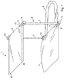
- a sunshade 1 comprises a shade 2, a headrest 3, an anchoring loop 4, and a support frame 5.
- the support frame 5 supports the shade 2 and headrest 3, and is adjustable.
- the anchoring loop 4 is attached to the support frame 5 at both ends and is weighted, for example, by being filled with a weighting material such as sand which is inserted into the loop 4 through an opening which is sealed during use to prevent escape of the weighting material.
- the anchoring loop 4 also serves as a handle for carrying the sunshade 1 when it is folded for transport.
- the support frame 5 allows movement of the various parts of the device and the sunshade is adjustable to enable the positions of the shade 2 and headrest 3 to be set to any one of a range of in-use positions with the shade 2 shading the headrest 3 as required.
- the position of the shade 2 relative to the headrest 3 may be varied, for example, over the course of the day to provide continued shade at the headrest 3 as the position of the sun changes. It is also possible to adjust the orientation of the shade 2, or headrest 3, or uprights relative to each other.
- the sunshade is suitable for use standalone on the beach as illustrated in Fig. 1 or in combination with a sun lounger L as illustrated in Figs. 2 and 3 .
- the weighted anchoring loop 4 anchors the sunshade in position securely and provides stability, for example if the weather conditions are windy.
- the anchoring loop 4 is also used to anchor the sunshade in position on a sun-lounger L whether the sun lounger L is arranged in at an incline or horizontally.
- this arrangement results in a counter-weight between the anchoring loop 4 and the headrest 3.
- this arrangement provides for further stability to hold the sunshade 1 in position.
- Figs. 4(a) to 4 (f) the steps of folding a sunshade 1 from an open in-use configuration to the closed configuration for transport are illustrated.
- the anchoring loop 4 anchors the sunshade in position on a support and when folded the anchoring loop 4 also serves as a carrying handle to enable a user to transport the folded sunshade with ease.
- the sunshade is closed by folding the shade 2 against the upright frame supports 6, 7 and thereafter folding the shade 2 and upright frame supports against the headrest 3.
- the support frame 5 comprises a base having a pair of base side arms 18 and 19 having front free ends 18a and 19a and rear ends 18b and 19b which are received into the joints 12 and 13 respectively.
- a frame cross member 9 extends between the side arms 18 and 19 and is connected to the joints 12 and 13.
- Upright frame members 6 and 7 extend upwardly from the joints 12 and 13.
- the headrest 3 comprises a cushion within a fabric cover which is supported on and in between the base side arms 18 and 19.
- the headrest 3 receives the base side arms 18 and 19 and is connected to the cross frame member 9 by means of wrapping an extended strip of fabric 14 around the cross frame member 9 and securing with a velcro strip, or other suitable securing means.
- the shade 2 comprises a sheet of fabric material such as canvas which terminates in seams 32 and 33 in which upper side arms 16 and 17 are slidably received.
- the shade 2 is secured to a frame cross member 8 by wrapping an extended strip of fabric 15 around the cross frame member 8 and securing with a velcro strip or other suitable securing means.
- the upper side arms 16 and 17 comprise front free ends 16a and 17a and rear ends 16b and 17b which are received into joints 10 and 11 respectively.
- the upper cross member 8 connects joints 10 and 11.
- the upright frame members 6 and 7 are connected to the joints 10 and 11 respectively.
- the joints 10 and 11 and 12 and 13 are adjustable to facilitate adjustment of the shade 2 in use.
- the joints 12 and 13 facilitate adjustment of the position of the base side arms 18 and 19 and the headrest 3 mounted therebetween relative to the upright frame members 6 and 7.
- the joints 10 and 11 facilitate adjustment of the position of the upper side arms 16 and 17 relative to the upright frame members 6 and 7 to allow for adjustment of the position of the shade 2 mounted therebetween relative to the upright frame members.
- the joints 10, 11, 12 and 13 are similar. Referring to Fig 9 , the joint 10 is described in more detail.
- the joint 10 comprises two main interacting joint members an outer fixed member 20 and an inner movable member 21 mounted together on a pin 25 which passes through an aperture 22, in the fixed member 20, and is threaded into a hex-nut (not shown) housed in a recess 23 in the inner movable member 21.
- the pin 25 is connected through the joint members 20, 21 under the loading of a spring 26.
- the upright frame member 6 is integrally moulded with the fixed member 20 and the cross bar 8 is integrally moulded with the inner movable member 21.
- the inner movable member 21 further comprises an aperture 28 for receiving the upper side arm 16.
- the abutting faces of the joint members 20 and 21 comprise a plurality of teeth 29 which facilitate the locking of joint at any of a plurality of positions.
- a sunshade 101 comprises a shade 102, a headrest 103, an anchoring loop 104, and a support frame 105.
- the sunshade 101 is similar to the sunshade 1 of Fig. 1 and similar features have been assigned similar reference numerals.
- the support frame 105 comprises a base having a pair of base side arms 118 and 119 connected by a cross member 109 at joints 112 and 113, and a top having a pair of upper side arms 116 and 117 connected by a cross member 108 at joints 110 and 111.
- Upright frame members 106 and 107 connect the top and base at the joints.
- the shade 102 comprises a sheet of fabric material such as canvas which terminates in seams 132 and 133 in which upper side arms 116 and 117 are slidably received.
- the headrest 103 which includes an integral cushion terminates in seams 134 and 135 in which lower side arms 118 and 119 are slidably received.
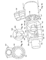
- the joints 110, 111, 112 and 113 are similar. Referring to Fig 12 , the joint 113 is described in more detail.
- the joint 113 comprises two main interacting joint members an outer fixed member 120 and an inner movable member 121 mounted together on a pin 125 which passes through an aperture 141, in the fixed member 120, and is received in an aperture in the inner movable member 121.
- the pin 125 is connected to the joint members 120, 121 under the loading of a spring 126.
- the pin 125 is held in place in the inner joint member 121 by means of a clip member 145 which corresponds in form with the end 146 of the pin 125 to enable interconnection.
- the upright frame member 107 is integrally moulded with the fixed member 120 and the cross bar 109 and arm 119 are integrally moulded with the inner movable member 121.
- the abutting faces 148 and 147 of the joint members 120 and 121 comprise a plurality of teeth 140 which facilitate the locking of joint at any one of a plurality of discrete positions.
- the joint 113 is illustrated in further detail in Figs. 13 to 19 .
- the inner movable member 121 has a cavity 143 therein and the outer fixed member 120 has an aperture 141 therethrough.
- the coupling pin 125 is inserted through the aperture 141 and into the cavity 143. This coupling action is illustrated in Figs. 16 and 17 .
- a protruding spline 200 is formed on the base of the coupling pin 125 ( Fig. 14 ).
- This spline 200 is mateable with a co-operating channel 201 in the base of the cavity 143 ( Figs. 13 and 16 ).
- the co-operating action of the spline 200 and channel 201 act to guide the pin 125 into the cavity 143 in a controlled manner. In particular it is only possible for a user to insert the pin 125 into the cavity 143 with the pin 125 in the upright configuration illustrated in Fig. 18 .
- the retainer clip member 145 is inserted into the cavity 143.
- the four protruding legs 202 of the retainer 145 engage against the four co-operating slots 203 in the clip 125. In this manner the clip 125 is held in position in the cavity 143.
- protruding fingers 204 are provided upstanding along the inner walls of the cavity 143 ( Fig. 16 ). These fingers 204 mate with four corresponding recess portions 205 in the retainer 145, upon insertion of the retainer 145 into the cavity 143. In this manner the retainer 145 is guided into the cavity 143 in a controlled manner.
- the coiled spring 126 acts to urge the outer fixed member 120 away from the inner movable member 121.
- the spring 126 thus assists in urging the members 120, 121 apart for repositioning of the members 120, 121 relative to one another.
- the toothed surfaces 148, 147 enable adjustment of the members 120, 121 in a ratchet action. It is not necessary to disassemble the outer fixed member 120 from the inner movable member 121 to enable adjustment. The members 120, 121 can be adjusted while coupled together.
- the position of a portion of the sunshade 1, for example, the shade 2 is adjusted by a user first of all exerting a force on the upper side arms 16, 17 to release the locked joints 10 and 11 and then moving the upper side arms 16 and 17 and the shade mounted thereon to the desired new position. Releasing the upper side arms 16, 17 causes the joints 10 and 11 to lock in the new position.
- the position of the upright frame members 6 and 7 relative to the headrest 3 and shade 2 and of the base side arms 18 and 19 relative to the upright frame members may be similarly adjusted.
- the sunshade 101 is adjusted in a similar manner.
- the arms and upright frame members of the support frame 105 are formed by injection moulding.
- the support frame 105 is lightweight by virtue of the moulded forms of the arms and members which include formations and recesses 151 and 152, and apertures 153.
- the upright member 107 is formed such that the tops and bottom ends 154 and 156 are narrower than the middle portion 156 thereof.
- the lightweight nature of the support frame 105 ensures that the sunshade is light and easy to carry.
- the support frame 105 may be pre-assembled. Thus the user is not required to assemble the support frame 105.
- the frame may be manufactured such that the upright, cross members, or side arms are integral with the inner or outer joint members.
- the frame may be manufactured such that the components are assembled together.
- the portable sunshade apparatus of the present invention has the advantages that it is robust without being unwieldy or awkward to handle.
- the sunshade is folded for transport and easily assembled from the folded configuration for use.
- the sunshade and headrest may be set at any of a range of positions in relation to each other.
- the use of four adjustable joints provides additional flexibility in setting the position of the shade relative to the headrest at it is possible to vary the angle and position both the shade and headrest relative to upright portion of the support frame.
- the joint allows the user to lock the sunshade in the selected position and also allows for adjustment of the position of the sunshade to any intermediate setting between the closed configuration and the maximum opened position.
- the shade is very easy to use since the user simply exerts a force on one of the extending arms which extend from the joint. No tools are required to adjust the joint and the user does not need to make manual adjustments at the joint.
- Assembly of the support frame may be performed quickly and easily.
- the guide means ensure that it is not possible to incorrectly assemble the support frame. In this manner, the support frame is fool-proof.
- the shade may be adjusted while lying down, which enhances the comfort and ease of use of the sunshade.
- the fabric of the shade and the headrest may be removed, for example for cleaning.
- the portable sunshade apparatus of the invention may be used either standalone on the beach or in combination with a sun lounger.
- the anchor of the sunshade facilities use on a sun lounger without the need for additional components such as clip or connection means to connect the sunshade to the lounger.
- the portable sunshade apparatus of the invention may be flexibly used with any type of sun lounger / sun chair.
Abstract
Description
- The invention relates to a portable sunshade apparatus for use on the beach or the like.
- Various sunshades are known. However, these are either generally large, unwieldy, difficult to use and/or ineffective in use, or smaller cheaper shades which are ineffective and easily damaged. Often sunshades are not suitable for use in windy conditions. Different types of sunshades are required for use on a beach and for use with a sun lounger. If a sunshade is to be connected to a sun lounger then additional components are needed, for example clips or fasteners. It may also be necessary to make some adjustment to the sun lounger to enable the sunshade to be received in place.
- There is therefore a need for an improved sunshade which will overcome at least some of these problems.
-
US Patent No. 4,796,734 discloses a shaded headrest comprising a cloth covering, and a vertical frame support panel affixed to a bottom frame base panel. - According to the invention there is provided a portable sunshade apparatus as claimed in
claim 1. - According to the invention the portable sunshade apparatus comprises a support frame for the shade. Preferably the support frame has adjustment means to facilitate adjustment of the shade, in use. Ideally the adjustment means is self locking. The adjustment means may include a releasable locking element. Most preferably the adjustment means is a ratchet system.
- According to the invention the support frame comprises: -
- a first frame member having an aperture therethrough, and a second frame member having a cavity therein; and
- a coupling pin insertable through the aperture in the first frame member and into the cavity in the second frame member to couple the first frame member to the second frame member.
- The support frame comprises a retainer to retain the coupling pin inserted through the aperture in the first frame member and into the cavity in the second frame member. The retainer is engagable with a part of the coupling pin in the cavity to retain the coupling pin. The retainer may comprise at least one engagement formation for engagement with at least one co-operating engagement formation on the part of the coupling pin. Most preferably the retainer is insertable into the cavity to engage the part of the coupling pin. The support frame may comprise a retainer guide to guide insertion of the retainer into the cavity. Preferably the retainer guide comprises at least one guide formation on the retainer for co-operating with at least one guide formation in the cavity. Ideally the retainer guide formation comprises a recess part and the cavity guide formation comprises a protruding part.
- The support frame may comprise a pin guide to guide insertion of the coupling pin into the cavity. Preferably the pin guide comprises at least one guide formation on the coupling pin for co-operating with at least one guide formation in the cavity. Ideally the coupling pin guide formation comprises a protruding part and the cavity guide formation comprises a recess part.
- The first frame member is preferably couplable to the second frame member in one of a plurality of discrete positions. Ideally the first frame member and the second frame member comprise co-operating ratchet formations.
- In one case the support frame comprises an urging member to urge the first frame member and the second frame member apart. The urging member preferably comprises a coiled spring between the first frame member and the second frame member.
- The anchor may be adapted for supporting the sunshade on a substantially flat surface, such as a beach. The anchor may be adapted for supporting the sunshade on a support such as a sun lounger or the like.
- The support frame may be formed by injection moulding.
- The support frame preferably has a lightweight form.
- The invention will be more clearly understood from the following description thereof given by way of example only in which:-
-
Fig. 1 is a perspective view of a portable sunshade apparatus according to the invention; -
Fig. 2 is a side view of the sunshade in use on a reclined sun lounger; -
Fig. 3 is a side view of the sunshade in use on a sun lounger at an angle to the upright; -
Fig. 4(a) is a view from the side of the sunshade in an open configuration, -
Figs. 4(b), 4(c), 4(d) and 4(e) are views from the side of the steps of folding the sunshade ofFig. 4(a) to the closed configuration; -
Fig. 4(f) is a view from the side of the sunshade in a closed configuration for transport; -
Fig. 5 is a view from the front of the frame of the sunshade; -
Figs. 6(a) and 6(b) are views from the front and side of an upright support of the sunshade ofFig. 5 ; -
Fig. 7 is a view from the side of the frame ofFig. 5 ; -
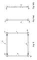
Fig. 8 is a view from above of the frame ofFig. 5 ; -
Fig. 9 is an exploded perspective view of the components of an adjustment means of a portable sunshade apparatus of the invention; -
Fig. 10 is a perspective view of a portable sunshade apparatus according to an alternative embodiment the invention; -
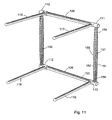
Fig. 11 is a perspective view of the frame of the sunshade ofFig. 10 ; -
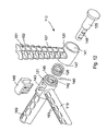
Fig. 12 is an exploded perspective view of the components of an adjustment means according to an alternative embodiment of a portable sunshade apparatus of the invention; -
Fig. 13 is a plan view of an aperture in an inner movable member of the sunshade ofFig. 12 ; -
Fig. 14 is a perspective view of a pin of the sunshade ofFig. 12 ; -
Fig. 15 is a perspective view of a clip member of the sunshade ofFig. 12 ; -
Fig. 16 is a perspective view illustrating assembly of the sunshade ofFig. 12 ; -
Fig. 17 is a plan view of the sunshade ofFig. 12 after assembly; -
Fig. 18 is a view along line A-A inFig. 17 ; and -
Fig. 19 is an end view of an aperture in an outer fixed member of the sunshade ofFig. 12 . - Referring to
Figs. 1 to 3 , asunshade 1 comprises ashade 2, aheadrest 3, ananchoring loop 4, and asupport frame 5. Thesupport frame 5 supports theshade 2 andheadrest 3, and is adjustable. Theanchoring loop 4 is attached to thesupport frame 5 at both ends and is weighted, for example, by being filled with a weighting material such as sand which is inserted into theloop 4 through an opening which is sealed during use to prevent escape of the weighting material. Theanchoring loop 4 also serves as a handle for carrying thesunshade 1 when it is folded for transport. - The
support frame 5 allows movement of the various parts of the device and the sunshade is adjustable to enable the positions of theshade 2 andheadrest 3 to be set to any one of a range of in-use positions with theshade 2 shading theheadrest 3 as required. The position of theshade 2 relative to theheadrest 3 may be varied, for example, over the course of the day to provide continued shade at theheadrest 3 as the position of the sun changes. It is also possible to adjust the orientation of theshade 2, orheadrest 3, or uprights relative to each other. - The sunshade is suitable for use standalone on the beach as illustrated in
Fig. 1 or in combination with a sun lounger L as illustrated inFigs. 2 and3 . In use, theweighted anchoring loop 4 anchors the sunshade in position securely and provides stability, for example if the weather conditions are windy. Theanchoring loop 4 is also used to anchor the sunshade in position on a sun-lounger L whether the sun lounger L is arranged in at an incline or horizontally. - Furthermore because the
anchoring loop 4 hangs from one side of the lounger L and theheadrest 3 is pressed against the lounger L by the weight of the user's head, this arrangement results in a counter-weight between the anchoringloop 4 and theheadrest 3. Thus this arrangement provides for further stability to hold thesunshade 1 in position. - Referring to
Figs. 4(a) to 4 (f) the steps of folding asunshade 1 from an open in-use configuration to the closed configuration for transport are illustrated. In use theanchoring loop 4 anchors the sunshade in position on a support and when folded theanchoring loop 4 also serves as a carrying handle to enable a user to transport the folded sunshade with ease. The sunshade is closed by folding theshade 2 against the upright frame supports 6, 7 and thereafter folding theshade 2 and upright frame supports against theheadrest 3. - Referring to
Figs. 1 and5 to 7 in more detail, thesupport frame 5 comprises a base having a pair ofbase side arms 18 and 19 having front free ends 18a and 19a andrear ends 18b and 19b which are received into thejoints frame cross member 9 extends between theside arms 18 and 19 and is connected to thejoints Upright frame members joints - The
headrest 3 comprises a cushion within a fabric cover which is supported on and in between thebase side arms 18 and 19. Theheadrest 3 receives thebase side arms 18 and 19 and is connected to thecross frame member 9 by means of wrapping an extended strip offabric 14 around thecross frame member 9 and securing with a velcro strip, or other suitable securing means. - The
shade 2 comprises a sheet of fabric material such as canvas which terminates inseams upper side arms shade 2 is secured to aframe cross member 8 by wrapping an extended strip offabric 15 around thecross frame member 8 and securing with a velcro strip or other suitable securing means. Theupper side arms rear ends joints upper cross member 8 connectsjoints upright frame members joints - The
joints shade 2 in use. Thejoints base side arms 18 and 19 and theheadrest 3 mounted therebetween relative to theupright frame members joints upper side arms upright frame members shade 2 mounted therebetween relative to the upright frame members. - The
joints Fig 9 , the joint 10 is described in more detail. The joint 10 comprises two main interacting joint members an outer fixedmember 20 and an innermovable member 21 mounted together on apin 25 which passes through anaperture 22, in the fixedmember 20, and is threaded into a hex-nut (not shown) housed in arecess 23 in the innermovable member 21. Thepin 25 is connected through thejoint members spring 26. - The
upright frame member 6 is integrally moulded with the fixedmember 20 and thecross bar 8 is integrally moulded with the innermovable member 21. The innermovable member 21 further comprises anaperture 28 for receiving theupper side arm 16. The abutting faces of thejoint members teeth 29 which facilitate the locking of joint at any of a plurality of positions. - No assembly of the
support frame 5 is required by the user. - Referring to
Figs. 10 and11 asunshade 101 comprises ashade 102, aheadrest 103, ananchoring loop 104, and asupport frame 105. Thesunshade 101 is similar to thesunshade 1 ofFig. 1 and similar features have been assigned similar reference numerals. - The
support frame 105 comprises a base having a pair ofbase side arms cross member 109 atjoints upper side arms cross member 108 atjoints Upright frame members - The
shade 102 comprises a sheet of fabric material such as canvas which terminates inseams upper side arms headrest 103, which includes an integral cushion terminates inseams lower side arms - The
joints Fig 12 , the joint 113 is described in more detail. The joint 113 comprises two main interacting joint members an outer fixedmember 120 and an innermovable member 121 mounted together on apin 125 which passes through anaperture 141, in the fixedmember 120, and is received in an aperture in the innermovable member 121. Thepin 125 is connected to thejoint members spring 126. Thepin 125 is held in place in the innerjoint member 121 by means of aclip member 145 which corresponds in form with theend 146 of thepin 125 to enable interconnection. - The
upright frame member 107 is integrally moulded with the fixedmember 120 and thecross bar 109 andarm 119 are integrally moulded with the innermovable member 121. The abutting faces 148 and 147 of thejoint members teeth 140 which facilitate the locking of joint at any one of a plurality of discrete positions. - The joint 113 is illustrated in further detail in
Figs. 13 to 19 . - The inner
movable member 121 has acavity 143 therein and the outer fixedmember 120 has anaperture 141 therethrough. To couple the outer fixedmember 120 to the innermovable member 121, thecoupling pin 125 is inserted through theaperture 141 and into thecavity 143. This coupling action is illustrated inFigs. 16 and17 . - A protruding
spline 200 is formed on the base of the coupling pin 125 (Fig. 14 ). Thisspline 200 is mateable with aco-operating channel 201 in the base of the cavity 143 (Figs. 13 and16 ). The co-operating action of thespline 200 andchannel 201 act to guide thepin 125 into thecavity 143 in a controlled manner. In particular it is only possible for a user to insert thepin 125 into thecavity 143 with thepin 125 in the upright configuration illustrated inFig. 18 . - To retain the
pin 125 in position inserted through theaperture 141 and into thecavity 143, and thus to retain the outer fixedmember 120 coupled to the innermovable member 121, theretainer clip member 145 is inserted into thecavity 143. Upon insertion into thecavity 143, the four protrudinglegs 202 of theretainer 145 engage against the fourco-operating slots 203 in theclip 125. In this manner theclip 125 is held in position in thecavity 143. - To guide insertion of the
retainer 145 into thecavity 143, four protrudingfingers 204 are provided upstanding along the inner walls of the cavity 143 (Fig. 16 ). Thesefingers 204 mate with fourcorresponding recess portions 205 in theretainer 145, upon insertion of theretainer 145 into thecavity 143. In this manner theretainer 145 is guided into thecavity 143 in a controlled manner. - The
coiled spring 126 acts to urge the outer fixedmember 120 away from the innermovable member 121. Thespring 126 thus assists in urging themembers members - The
toothed surfaces members member 120 from the innermovable member 121 to enable adjustment. Themembers - In use, the position of a portion of the
sunshade 1, for example, theshade 2 is adjusted by a user first of all exerting a force on theupper side arms joints upper side arms upper side arms joints upright frame members headrest 3 andshade 2 and of thebase side arms 18 and 19 relative to the upright frame members may be similarly adjusted. Thesunshade 101 is adjusted in a similar manner. - The arms and upright frame members of the
support frame 105 are formed by injection moulding. Thesupport frame 105 is lightweight by virtue of the moulded forms of the arms and members which include formations and recesses 151 and 152, andapertures 153. Theupright member 107 is formed such that the tops and bottom ends 154 and 156 are narrower than themiddle portion 156 thereof. - The lightweight nature of the
support frame 105 ensures that the sunshade is light and easy to carry. - The
support frame 105 may be pre-assembled. Thus the user is not required to assemble thesupport frame 105. - The frame may be manufactured such that the upright, cross members, or side arms are integral with the inner or outer joint members. Alternatively the frame may be manufactured such that the components are assembled together.
- The portable sunshade apparatus of the present invention has the advantages that it is robust without being unwieldy or awkward to handle. The sunshade is folded for transport and easily assembled from the folded configuration for use. The sunshade and headrest may be set at any of a range of positions in relation to each other. The use of four adjustable joints provides additional flexibility in setting the position of the shade relative to the headrest at it is possible to vary the angle and position both the shade and headrest relative to upright portion of the support frame. The joint allows the user to lock the sunshade in the selected position and also allows for adjustment of the position of the sunshade to any intermediate setting between the closed configuration and the maximum opened position.
- In addition the shade is very easy to use since the user simply exerts a force on one of the extending arms which extend from the joint. No tools are required to adjust the joint and the user does not need to make manual adjustments at the joint.
- Assembly of the support frame may be performed quickly and easily.
- The guide means ensure that it is not possible to incorrectly assemble the support frame. In this manner, the support frame is fool-proof.
- The shade may be adjusted while lying down, which enhances the comfort and ease of use of the sunshade.
- The fabric of the shade and the headrest may be removed, for example for cleaning.
- The portable sunshade apparatus of the invention may be used either standalone on the beach or in combination with a sun lounger. The anchor of the sunshade facilities use on a sun lounger without the need for additional components such as clip or connection means to connect the sunshade to the lounger. In addition it is not necessary to modify the lounger in any way to enable use of the sunshade. Thus the portable sunshade apparatus of the invention may be flexibly used with any type of sun lounger / sun chair.
- The invention is not limited to the embodiments hereinbefore described which may be varied in detail.
Claims (15)
- A portable sunshade apparatus (101) comprising: -a shade (102);a support frame (105) for the shade (102);the support frame (105) comprising: -a first frame member (107) having an aperture (141) therethrough, and a second frame member (109) having a cavity (143) therein; anda coupling pin (125) insertable through the aperture (141) in the first frame member (107) and into the cavity (143) in the second frame member (109) to couple the first frame member (107) to the second frame member (109);the support frame comprising a retainer (145) to retain the coupling pin (125) inserted through the aperture (141) in the first frame member (107) and into the cavity (143) in the second frame member (109);the retainer (145) being engagable with a part of the coupling pin (125) in the cavity (143) to retain the coupling pin (125).
- A portable sunshade apparatus as claimed in claim 1 wherein the retainer (145) comprises at least one engagement formation (202) for engagement with at least one co-operating engagement formation (203) on the part of the coupling pin (125).
- A portable sunshade apparatus as claimed in claim 1 or 2 wherein the retainer (145) is insertable into the cavity (143) to engage the part of the coupling pin (125).
- A portable sunshade apparatus as claimed in claim 4 wherein the support frame (105) comprises a retainer guide to guide insertion of the retainer (145) into the cavity (143).
- A portable sunshade apparatus as claimed in claim 4 wherein the retainer guide comprises at least one guide formation (205) on the retainer (145) for co-operating with at least one guide formation (204) in the cavity (143).
- A portable sunshade apparatus as claimed in claim 5 wherein the retainer guide formation comprises a recess part (205) and the cavity guide formation comprises a protruding part (204).
- A portable sunshade apparatus as claimed in any of claims 1 to 6 wherein the support frame (105) comprises a pin guide to guide insertion of the coupling pin (125) into the cavity (143).
- A portable sunshade apparatus as claimed in claim 7 wherein the pin guide comprises at least one guide formation (200) on the coupling pin (125) for co-operating with at least one guide formation (201) in the cavity (143).
- A portable sunshade apparatus as claimed in claim 8 wherein the coupling pin guide formation comprises a protruding part (200) and the cavity guide formation comprises a recess part (201).
- A portable sunshade apparatus as claimed in any of claims 1 to 9 wherein the first frame member (107) is couplable to the second frame member (109) in one of a plurality of discrete positions.
- A portable sunshade apparatus as claimed in claim 10 wherein the first frame member (107) and the second frame member (109) comprise co-operating ratchet formations (140).
- A portable sunshade apparatus as claimed in any of claims 1 to 11 wherein the support frame (105) comprises an urging member (126) to urge the first frame member (107) and the second frame member (109) apart.
- A portable sunshade apparatus as claimed in claim 12 wherein the urging member comprises a coiled spring (126) between the first frame member (107) and the second frame member (109).
- A portable sunshade apparatus as claimed in any preceding claim wherein the support frame (105) is formed by injection moulding.
- A portable sunshade apparatus as claimed in any preceding claim wherein the support frame (105) has a lightweight form.
Applications Claiming Priority (2)
| Application Number | Priority Date | Filing Date | Title |
|---|---|---|---|
| IE20030681 | 2003-09-17 | ||
| IE20030681 | 2003-09-17 |
Publications (3)
| Publication Number | Publication Date |
|---|---|
| EP1516565A2 EP1516565A2 (en) | 2005-03-23 |
| EP1516565A3 EP1516565A3 (en) | 2006-05-24 |
| EP1516565B1 true EP1516565B1 (en) | 2008-04-09 |
Family
ID=34179255
Family Applications (1)
| Application Number | Title | Priority Date | Filing Date |
|---|---|---|---|
| EP04394059A Not-in-force EP1516565B1 (en) | 2003-09-17 | 2004-09-17 | A sunshade |
Country Status (8)
| Country | Link |
|---|---|
| US (1) | US7347217B2 (en) |
| EP (1) | EP1516565B1 (en) |
| AT (1) | ATE391441T1 (en) |
| DE (1) | DE602004012935T2 (en) |
| ES (1) | ES2305702T3 (en) |
| HK (1) | HK1074365A1 (en) |
| IE (1) | IE20040627A1 (en) |
| ZA (1) | ZA200407480B (en) |
Families Citing this family (18)
| Publication number | Priority date | Publication date | Assignee | Title |
|---|---|---|---|---|
| US7931040B2 (en) * | 2008-05-12 | 2011-04-26 | John C. Holacka | Portable shelter |
| US20110079261A1 (en) * | 2009-10-07 | 2011-04-07 | Sportsman Corporation | Joint assembly |
| US20110303256A1 (en) * | 2010-06-11 | 2011-12-15 | Elaine Ashley | Portable sunshade apparatus |
| US20160010358A1 (en) * | 2010-06-11 | 2016-01-14 | Elaine Ashley | Dual-use portable sunshade apparatus |
| US8176928B2 (en) | 2010-07-11 | 2012-05-15 | Shadiant, Llc | Method of setting up a portable barrier |
| US8171948B2 (en) | 2010-07-11 | 2012-05-08 | Shadiant, Llc | Portable barrier |
| US11898367B2 (en) | 2010-07-11 | 2024-02-13 | Shadiant, Llc | Portable barrier |
| BRMU9001475Y1 (en) * | 2010-08-13 | 2018-01-16 | Stoll Stiv | ADJUSTABLE FACE SOLAR PROTECTION ACCESSORY |
| US8464379B1 (en) | 2012-10-26 | 2013-06-18 | Susan Zajac | Stretcher shade |
| US9126093B1 (en) * | 2013-02-07 | 2015-09-08 | Atlantic Recreation, Inc, ; | System for retractable tennis court shade device |
| US9493963B2 (en) | 2013-09-17 | 2016-11-15 | Shadiant, Llc | Portable barrier and associated method of use |
| US9085914B1 (en) * | 2013-09-27 | 2015-07-21 | Gerald Wayne Kulm | Blind assembly |
| US9874038B2 (en) | 2015-08-10 | 2018-01-23 | Jalal Pashandi | Collapsible sun shade |
| US10022002B2 (en) * | 2016-11-11 | 2018-07-17 | Robert C V Chen | Extensible Z accessorized travel head rest |
| USD828963S1 (en) * | 2017-10-23 | 2018-09-18 | Ingmar Hansen | Pet resting enclosure |
| US10888167B2 (en) * | 2019-04-23 | 2021-01-12 | Brian Y. Zhu | Travel pillow |
| US11350752B2 (en) * | 2019-11-19 | 2022-06-07 | GoPlus Corp. | Systems and methods for a portable chair with sunshade |
| USD955122S1 (en) | 2019-11-19 | 2022-06-21 | GoPlus Corp. | Chair |
Family Cites Families (27)
| Publication number | Priority date | Publication date | Assignee | Title |
|---|---|---|---|---|
| GB348821A (en) | 1929-10-09 | 1931-05-21 | Josef Kotausek | Reposing mat with foldable awning |
| US2070484A (en) * | 1935-11-07 | 1937-02-09 | Nelson M Jones | Beach accessory |
| US2109881A (en) * | 1936-06-25 | 1938-03-01 | Goldberg David | Bathing beach accessory |
| US2290786A (en) * | 1941-02-15 | 1942-07-21 | Varady Armin | Folding bed rest for beaches, camps, etc. |
| US2543597A (en) * | 1947-09-29 | 1951-02-27 | William W Peery | Beach bag and canopy |
| US2584432A (en) | 1948-12-04 | 1952-02-05 | Marco Joseph C De | Combined beach bag and sunshade |
| US2771125A (en) * | 1954-04-06 | 1956-11-20 | Albert L Dobbins | Adjustable and foldable canopy |
| US2932833A (en) * | 1956-09-19 | 1960-04-19 | Wambach Katharina | Combined head-rest and sun-shade for seashore beaches |
| US2819776A (en) | 1956-12-28 | 1958-01-14 | Alfred D Balsam | Combined sun shade and article carrier |
| US3241160A (en) * | 1963-06-20 | 1966-03-22 | Escobar Pablo Cesar | Portable folding head rest |
| US3298477A (en) | 1966-02-09 | 1967-01-17 | Martinez Erasmo | Convertible carrier, head rest and sun shade |
| US3404915A (en) * | 1967-03-16 | 1968-10-08 | Filho Jose Luiz De Souza | Beach chair and cot |
| US3651847A (en) | 1970-06-09 | 1972-03-28 | Carole C Casamassima | Mini-brella |
| FR2400873A1 (en) | 1977-08-24 | 1979-03-23 | Galko Jacques | Combined beach towel and bag - consists of trapezium-shaped material sheet with sprung steel strip along edges with attachments and pocket |
| US4470630A (en) * | 1982-03-22 | 1984-09-11 | Shields Michael P | Portable folding chair |
| IL67800A (en) | 1983-01-31 | 1986-11-30 | Lerner Reuben | Head rest and sun shade |
| US4739784A (en) * | 1986-09-17 | 1988-04-26 | Paul Fast | Sun and wind shield |
| US4796734A (en) * | 1988-03-11 | 1989-01-10 | Distasio Shawn M | Toteable shaded headrest |
| FR2666976A1 (en) | 1990-09-21 | 1992-03-27 | Plastica Confort | MATTRESSES, ESPECIALLY BEACH MATTRESSES. |
| US5425567A (en) * | 1991-06-26 | 1995-06-20 | Albecker, Iii; Walter J. | Backrests/legless leisure chairs and methods for making cushions |
| US5320405A (en) * | 1992-08-24 | 1994-06-14 | Bacchi Of California, Inc. | Portable sunshade using sleeve means for removable attachment to the back of a lounge chair |
| FR2713265B1 (en) | 1993-12-03 | 1996-12-13 | Prieto Charles | Individual sun visor. |
| US5515564A (en) | 1994-08-02 | 1996-05-14 | Lyons; Thomas R. | Sun shield |
| US5823217A (en) * | 1996-04-10 | 1998-10-20 | Greenbest, Inc. | Sunshade |
| US5690134A (en) | 1996-12-23 | 1997-11-25 | Mccauley; William E. | Portable sunshade canopy |
| IES20020277A2 (en) | 2001-04-17 | 2002-10-16 | Joan Mary Bree | A sunshade |
| US6383085B1 (en) * | 2001-05-24 | 2002-05-07 | Shin Yeh Enterprise Co., Ltd. | Swing assembly with a canopy |
-
2004
- 2004-09-17 AT AT04394059T patent/ATE391441T1/en not_active IP Right Cessation
- 2004-09-17 US US10/942,800 patent/US7347217B2/en active Active
- 2004-09-17 IE IE20040627A patent/IE20040627A1/en not_active IP Right Cessation
- 2004-09-17 ES ES04394059T patent/ES2305702T3/en active Active
- 2004-09-17 DE DE602004012935T patent/DE602004012935T2/en active Active
- 2004-09-17 ZA ZA200407480A patent/ZA200407480B/en unknown
- 2004-09-17 EP EP04394059A patent/EP1516565B1/en not_active Not-in-force
-
2005
- 2005-09-22 HK HK05108330A patent/HK1074365A1/en not_active IP Right Cessation
Also Published As
| Publication number | Publication date |
|---|---|
| US20050056309A1 (en) | 2005-03-17 |
| US7347217B2 (en) | 2008-03-25 |
| DE602004012935T2 (en) | 2009-05-07 |
| ATE391441T1 (en) | 2008-04-15 |
| ZA200407480B (en) | 2005-05-24 |
| IE20040627A1 (en) | 2005-05-04 |
| EP1516565A2 (en) | 2005-03-23 |
| EP1516565A3 (en) | 2006-05-24 |
| DE602004012935D1 (en) | 2008-05-21 |
| HK1074365A1 (en) | 2005-11-11 |
| ES2305702T3 (en) | 2008-11-01 |
Similar Documents
| Publication | Publication Date | Title |
|---|---|---|
| EP1516565B1 (en) | A sunshade | |
| US7243990B1 (en) | Sunshade apparatus | |
| US5934529A (en) | Baby backpack sun/rain shade device | |
| US5797650A (en) | Sun shade attachment | |
| CA2182991C (en) | Cover assembly for a deck chair | |
| US6386986B1 (en) | Child swing | |
| US7748433B2 (en) | Clip for collapsible auto shade | |
| US6789557B1 (en) | Portable and collapsible sunshade apparatus for providing shade to a user having a universal clip to attach the sunshade to any type of beach chair or lounge chair | |
| US5967601A (en) | Sunshade apparatus for recreational chair | |
| US6966084B2 (en) | Support and method of using the same | |
| US20080018146A1 (en) | Sunshade apparatus | |
| US6908148B2 (en) | Sun shelter for child car seat | |
| US20070145792A1 (en) | Retractable canopy | |
| US20210007497A1 (en) | Portable Seat Awning | |
| US9936811B2 (en) | Portable seat awning | |
| KR20110118718A (en) | Folding canopy chair | |
| US7168759B2 (en) | Folding sunshade for car seat | |
| US11584208B2 (en) | Method of enhancing rain and sun protection using a rain and sun shield for golf carts | |
| US20080142062A1 (en) | Compact portable sunshade for face protection | |
| WO2015009738A1 (en) | Adjustable free standing shelter | |
| KR101467473B1 (en) | Collapsable chair provided with blind | |
| WO2002082941A1 (en) | A sunshade with a pillow convertible into a bag | |
| AU2003200804B2 (en) | Pivotal dock structure for canopy of strollers | |
| KR20230140879A (en) | Parasol for leisure chair | |
| AU2001278202A1 (en) | Collapsible shade for a mat |
Legal Events
| Date | Code | Title | Description |
|---|---|---|---|
| PUAI | Public reference made under article 153(3) epc to a published international application that has entered the european phase |
Free format text: ORIGINAL CODE: 0009012 |
|
| AK | Designated contracting states |
Kind code of ref document: A2 Designated state(s): AT BE BG CH CY CZ DE DK EE ES FI FR GB GR HU IE IT LI LU MC NL PL PT RO SE SI SK TR |
|
| AX | Request for extension of the european patent |
Extension state: AL HR LT LV MK |
|
| REG | Reference to a national code |
Ref country code: HK Ref legal event code: DE Ref document number: 1074365 Country of ref document: HK |
|
| PUAL | Search report despatched |
Free format text: ORIGINAL CODE: 0009013 |
|
| AK | Designated contracting states |
Kind code of ref document: A3 Designated state(s): AT BE BG CH CY CZ DE DK EE ES FI FR GB GR HU IE IT LI LU MC NL PL PT RO SE SI SK TR |
|
| AX | Request for extension of the european patent |
Extension state: AL HR LT LV MK |
|
| 17P | Request for examination filed |
Effective date: 20060826 |
|
| 17Q | First examination report despatched |
Effective date: 20061117 |
|
| AKX | Designation fees paid |
Designated state(s): AT BE BG CH CY CZ DE DK EE ES FI FR GB GR HU IE IT LI LU MC NL PL PT RO SE SI SK TR |
|
| GRAP | Despatch of communication of intention to grant a patent |
Free format text: ORIGINAL CODE: EPIDOSNIGR1 |
|
| GRAS | Grant fee paid |
Free format text: ORIGINAL CODE: EPIDOSNIGR3 |
|
| GRAA | (expected) grant |
Free format text: ORIGINAL CODE: 0009210 |
|
| AK | Designated contracting states |
Kind code of ref document: B1 Designated state(s): AT BE BG CH CY CZ DE DK EE ES FI FR GB GR HU IE IT LI LU MC NL PL PT RO SE SI SK TR |
|
| REG | Reference to a national code |
Ref country code: GB Ref legal event code: FG4D |
|
| REG | Reference to a national code |
Ref country code: CH Ref legal event code: EP |
|
| REG | Reference to a national code |
Ref country code: IE Ref legal event code: FG4D |
|
| REF | Corresponds to: |
Ref document number: 602004012935 Country of ref document: DE Date of ref document: 20080521 Kind code of ref document: P |
|
| REG | Reference to a national code |
Ref country code: HK Ref legal event code: GR Ref document number: 1074365 Country of ref document: HK |
|
| PG25 | Lapsed in a contracting state [announced via postgrant information from national office to epo] |
Ref country code: SI Free format text: LAPSE BECAUSE OF FAILURE TO SUBMIT A TRANSLATION OF THE DESCRIPTION OR TO PAY THE FEE WITHIN THE PRESCRIBED TIME-LIMIT Effective date: 20080409 |
|
| NLV1 | Nl: lapsed or annulled due to failure to fulfill the requirements of art. 29p and 29m of the patents act | ||
| PG25 | Lapsed in a contracting state [announced via postgrant information from national office to epo] |
Ref country code: NL Free format text: LAPSE BECAUSE OF FAILURE TO SUBMIT A TRANSLATION OF THE DESCRIPTION OR TO PAY THE FEE WITHIN THE PRESCRIBED TIME-LIMIT Effective date: 20080409 Ref country code: PT Free format text: LAPSE BECAUSE OF FAILURE TO SUBMIT A TRANSLATION OF THE DESCRIPTION OR TO PAY THE FEE WITHIN THE PRESCRIBED TIME-LIMIT Effective date: 20080909 Ref country code: BG Free format text: LAPSE BECAUSE OF FAILURE TO SUBMIT A TRANSLATION OF THE DESCRIPTION OR TO PAY THE FEE WITHIN THE PRESCRIBED TIME-LIMIT Effective date: 20080709 Ref country code: FI Free format text: LAPSE BECAUSE OF FAILURE TO SUBMIT A TRANSLATION OF THE DESCRIPTION OR TO PAY THE FEE WITHIN THE PRESCRIBED TIME-LIMIT Effective date: 20080409 |
|
| REG | Reference to a national code |
Ref country code: ES Ref legal event code: FG2A Ref document number: 2305702 Country of ref document: ES Kind code of ref document: T3 |
|
| PG25 | Lapsed in a contracting state [announced via postgrant information from national office to epo] |
Ref country code: AT Free format text: LAPSE BECAUSE OF FAILURE TO SUBMIT A TRANSLATION OF THE DESCRIPTION OR TO PAY THE FEE WITHIN THE PRESCRIBED TIME-LIMIT Effective date: 20080409 Ref country code: PL Free format text: LAPSE BECAUSE OF FAILURE TO SUBMIT A TRANSLATION OF THE DESCRIPTION OR TO PAY THE FEE WITHIN THE PRESCRIBED TIME-LIMIT Effective date: 20080409 |
|
| ET | Fr: translation filed | ||
| PG25 | Lapsed in a contracting state [announced via postgrant information from national office to epo] |
Ref country code: SE Free format text: LAPSE BECAUSE OF FAILURE TO SUBMIT A TRANSLATION OF THE DESCRIPTION OR TO PAY THE FEE WITHIN THE PRESCRIBED TIME-LIMIT Effective date: 20080709 Ref country code: DK Free format text: LAPSE BECAUSE OF FAILURE TO SUBMIT A TRANSLATION OF THE DESCRIPTION OR TO PAY THE FEE WITHIN THE PRESCRIBED TIME-LIMIT Effective date: 20080409 Ref country code: CZ Free format text: LAPSE BECAUSE OF FAILURE TO SUBMIT A TRANSLATION OF THE DESCRIPTION OR TO PAY THE FEE WITHIN THE PRESCRIBED TIME-LIMIT Effective date: 20080409 |
|
| PLBE | No opposition filed within time limit |
Free format text: ORIGINAL CODE: 0009261 |
|
| STAA | Information on the status of an ep patent application or granted ep patent |
Free format text: STATUS: NO OPPOSITION FILED WITHIN TIME LIMIT |
|
| PG25 | Lapsed in a contracting state [announced via postgrant information from national office to epo] |
Ref country code: BE Free format text: LAPSE BECAUSE OF FAILURE TO SUBMIT A TRANSLATION OF THE DESCRIPTION OR TO PAY THE FEE WITHIN THE PRESCRIBED TIME-LIMIT Effective date: 20080409 Ref country code: SK Free format text: LAPSE BECAUSE OF FAILURE TO SUBMIT A TRANSLATION OF THE DESCRIPTION OR TO PAY THE FEE WITHIN THE PRESCRIBED TIME-LIMIT Effective date: 20080409 Ref country code: RO Free format text: LAPSE BECAUSE OF FAILURE TO SUBMIT A TRANSLATION OF THE DESCRIPTION OR TO PAY THE FEE WITHIN THE PRESCRIBED TIME-LIMIT Effective date: 20080409 |
|
| 26N | No opposition filed |
Effective date: 20090112 |
|
| PG25 | Lapsed in a contracting state [announced via postgrant information from national office to epo] |
Ref country code: EE Free format text: LAPSE BECAUSE OF FAILURE TO SUBMIT A TRANSLATION OF THE DESCRIPTION OR TO PAY THE FEE WITHIN THE PRESCRIBED TIME-LIMIT Effective date: 20080409 Ref country code: MC Free format text: LAPSE BECAUSE OF NON-PAYMENT OF DUE FEES Effective date: 20080930 |
|
| REG | Reference to a national code |
Ref country code: CH Ref legal event code: PL |
|
| PG25 | Lapsed in a contracting state [announced via postgrant information from national office to epo] |
Ref country code: CY Free format text: LAPSE BECAUSE OF FAILURE TO SUBMIT A TRANSLATION OF THE DESCRIPTION OR TO PAY THE FEE WITHIN THE PRESCRIBED TIME-LIMIT Effective date: 20080409 |
|
| PG25 | Lapsed in a contracting state [announced via postgrant information from national office to epo] |
Ref country code: CH Free format text: LAPSE BECAUSE OF NON-PAYMENT OF DUE FEES Effective date: 20080930 Ref country code: LI Free format text: LAPSE BECAUSE OF NON-PAYMENT OF DUE FEES Effective date: 20080930 |
|
| PG25 | Lapsed in a contracting state [announced via postgrant information from national office to epo] |
Ref country code: LU Free format text: LAPSE BECAUSE OF NON-PAYMENT OF DUE FEES Effective date: 20080917 Ref country code: HU Free format text: LAPSE BECAUSE OF FAILURE TO SUBMIT A TRANSLATION OF THE DESCRIPTION OR TO PAY THE FEE WITHIN THE PRESCRIBED TIME-LIMIT Effective date: 20081010 |
|
| PG25 | Lapsed in a contracting state [announced via postgrant information from national office to epo] |
Ref country code: TR Free format text: LAPSE BECAUSE OF FAILURE TO SUBMIT A TRANSLATION OF THE DESCRIPTION OR TO PAY THE FEE WITHIN THE PRESCRIBED TIME-LIMIT Effective date: 20080409 |
|
| PG25 | Lapsed in a contracting state [announced via postgrant information from national office to epo] |
Ref country code: GR Free format text: LAPSE BECAUSE OF FAILURE TO SUBMIT A TRANSLATION OF THE DESCRIPTION OR TO PAY THE FEE WITHIN THE PRESCRIBED TIME-LIMIT Effective date: 20080710 |
|
| PGFP | Annual fee paid to national office [announced via postgrant information from national office to epo] |
Ref country code: DE Payment date: 20140911 Year of fee payment: 11 |
|
| PGFP | Annual fee paid to national office [announced via postgrant information from national office to epo] |
Ref country code: IT Payment date: 20140911 Year of fee payment: 11 |
|
| PGFP | Annual fee paid to national office [announced via postgrant information from national office to epo] |
Ref country code: ES Payment date: 20140930 Year of fee payment: 11 Ref country code: FR Payment date: 20140911 Year of fee payment: 11 |
|
| REG | Reference to a national code |
Ref country code: DE Ref legal event code: R119 Ref document number: 602004012935 Country of ref document: DE |
|
| PG25 | Lapsed in a contracting state [announced via postgrant information from national office to epo] |
Ref country code: IT Free format text: LAPSE BECAUSE OF NON-PAYMENT OF DUE FEES Effective date: 20150917 |
|
| REG | Reference to a national code |
Ref country code: FR Ref legal event code: ST Effective date: 20160531 |
|
| PG25 | Lapsed in a contracting state [announced via postgrant information from national office to epo] |
Ref country code: DE Free format text: LAPSE BECAUSE OF NON-PAYMENT OF DUE FEES Effective date: 20160401 |
|
| PG25 | Lapsed in a contracting state [announced via postgrant information from national office to epo] |
Ref country code: FR Free format text: LAPSE BECAUSE OF NON-PAYMENT OF DUE FEES Effective date: 20150930 |
|
| REG | Reference to a national code |
Ref country code: ES Ref legal event code: FD2A Effective date: 20161027 |
|
| PGFP | Annual fee paid to national office [announced via postgrant information from national office to epo] |
Ref country code: GB Payment date: 20160913 Year of fee payment: 13 |
|
| PG25 | Lapsed in a contracting state [announced via postgrant information from national office to epo] |
Ref country code: ES Free format text: LAPSE BECAUSE OF NON-PAYMENT OF DUE FEES Effective date: 20150918 |
|
| GBPC | Gb: european patent ceased through non-payment of renewal fee |
Effective date: 20170917 |
|
| PG25 | Lapsed in a contracting state [announced via postgrant information from national office to epo] |
Ref country code: GB Free format text: LAPSE BECAUSE OF NON-PAYMENT OF DUE FEES Effective date: 20170917 |
|
| PGFP | Annual fee paid to national office [announced via postgrant information from national office to epo] |
Ref country code: IE Payment date: 20180916 Year of fee payment: 15 |
|
| PG25 | Lapsed in a contracting state [announced via postgrant information from national office to epo] |
Ref country code: IE Free format text: LAPSE BECAUSE OF NON-PAYMENT OF DUE FEES Effective date: 20190917 |