EP1420206B1 - Dispositif de détection de la combustion avec un générateur thermoélectrique - Google Patents
Dispositif de détection de la combustion avec un générateur thermoélectrique Download PDFInfo
- Publication number
- EP1420206B1 EP1420206B1 EP20030380257 EP03380257A EP1420206B1 EP 1420206 B1 EP1420206 B1 EP 1420206B1 EP 20030380257 EP20030380257 EP 20030380257 EP 03380257 A EP03380257 A EP 03380257A EP 1420206 B1 EP1420206 B1 EP 1420206B1
- Authority
- EP
- European Patent Office
- Prior art keywords
- thermoelectric
- cell
- cells
- detection apparatus
- flat
- Prior art date
- Legal status (The legal status is an assumption and is not a legal conclusion. Google has not performed a legal analysis and makes no representation as to the accuracy of the status listed.)
- Expired - Fee Related
Links
Images

Classifications
-
- F—MECHANICAL ENGINEERING; LIGHTING; HEATING; WEAPONS; BLASTING
- F23—COMBUSTION APPARATUS; COMBUSTION PROCESSES
- F23N—REGULATING OR CONTROLLING COMBUSTION
- F23N5/00—Systems for controlling combustion
- F23N5/02—Systems for controlling combustion using devices responsive to thermal changes or to thermal expansion of a medium
- F23N5/10—Systems for controlling combustion using devices responsive to thermal changes or to thermal expansion of a medium using thermocouples
- F23N5/102—Systems for controlling combustion using devices responsive to thermal changes or to thermal expansion of a medium using thermocouples using electronic means
-
- F—MECHANICAL ENGINEERING; LIGHTING; HEATING; WEAPONS; BLASTING
- F23—COMBUSTION APPARATUS; COMBUSTION PROCESSES
- F23D—BURNERS
- F23D14/00—Burners for combustion of a gas, e.g. of a gas stored under pressure as a liquid
- F23D14/46—Details, e.g. noise reduction means
- F23D14/72—Safety devices, e.g. operative in case of failure of gas supply
- F23D14/725—Protection against flame failure by using flame detection devices
-
- F—MECHANICAL ENGINEERING; LIGHTING; HEATING; WEAPONS; BLASTING
- F23—COMBUSTION APPARATUS; COMBUSTION PROCESSES
- F23N—REGULATING OR CONTROLLING COMBUSTION
- F23N5/00—Systems for controlling combustion
- F23N5/24—Preventing development of abnormal or undesired conditions, i.e. safety arrangements
- F23N5/242—Preventing development of abnormal or undesired conditions, i.e. safety arrangements using electronic means
-
- F—MECHANICAL ENGINEERING; LIGHTING; HEATING; WEAPONS; BLASTING
- F28—HEAT EXCHANGE IN GENERAL
- F28D—HEAT-EXCHANGE APPARATUS, NOT PROVIDED FOR IN ANOTHER SUBCLASS, IN WHICH THE HEAT-EXCHANGE MEDIA DO NOT COME INTO DIRECT CONTACT
- F28D15/00—Heat-exchange apparatus with the intermediate heat-transfer medium in closed tubes passing into or through the conduit walls ; Heat-exchange apparatus employing intermediate heat-transfer medium or bodies
-
- F—MECHANICAL ENGINEERING; LIGHTING; HEATING; WEAPONS; BLASTING
- F23—COMBUSTION APPARATUS; COMBUSTION PROCESSES
- F23M—CASINGS, LININGS, WALLS OR DOORS SPECIALLY ADAPTED FOR COMBUSTION CHAMBERS, e.g. FIREBRIDGES; DEVICES FOR DEFLECTING AIR, FLAMES OR COMBUSTION PRODUCTS IN COMBUSTION CHAMBERS; SAFETY ARRANGEMENTS SPECIALLY ADAPTED FOR COMBUSTION APPARATUS; DETAILS OF COMBUSTION CHAMBERS, NOT OTHERWISE PROVIDED FOR
- F23M2900/00—Special features of, or arrangements for combustion chambers
- F23M2900/13003—Energy recovery by thermoelectric elements, e.g. by Peltier/Seebeck effect, arranged in the combustion plant
Definitions
- the present invention relates to an apparatus for detecting gas combustion in a domestic environment heater or water heater, provided with a pilot burner, an igniter and a thermoelectric unit that generates a voltage for the supply of a safety valve and a main valve, using only flat Peltier type cells for the thermoelectric generation.
- thermoelectric generator In a combustion control system of a free-standing gas heater, a self-contained thermoelectric generator is required for supplying both the electrical ignition and flame detection circuits and at least two electromagnetic valves that supply gas to the pilot burner and to the main burner.
- Combustion control systems of this type are already known, as for instance that disclosed in US-A-4770629 , wherein the thermoelectric unit is built with a thermopile heated directly by the pilot flame, from which two respective DC voltage values are obtained for two valves.
- the safety device In unventilated domestic environment heaters, there is a further requirement that the safety device should detect combustion anomalies that cause a deficiency in the pilot flame, acting as a room air oxygen depletion sensor (ODS).
- ODS room air oxygen depletion sensor
- thermoelectric generating elements are cylindrical with a tip positioned at a given distance from the pilot flame for precise heating.
- thermoelectric deveices for generating a DC voltage is well known in free-standing heater appliances, as for instance in US-6335572-B1 and DE-4301872-A , which are built with flat semiconductor PN junction cells, wherein both flat outer faces of the thermoelectric cell are connected respectively to the heater appliance heating and cooling means.
- the thermoelectric unit disclosed in US-6335572-B1 is heated by a pilot burner and generates a DC voltage to supply an electronic control circuit, including a safety valve solenoid, a main gas supply valve solenoid and a rechargeable battery.
- the object of the present invention is an apparatus for the detection of gas combustion in an environment heater or in a water heater, adapted for flame detection including oxygen depletion, and supplying two separate dc voltages for a heater safety valve and a main valve, by means of a pilot burner and a thermoelectric generator unit made up of at least one flat Peltier type cell, wherein the generator is heated by a heat transmitter element licked by the pilot flame.
- One objective of the invention is to provide the combustion detection apparatus with a compact thermoelectric unit constructed by means of flat Peltier type semiconductor PN junction cells of higher efficiency and quicker response than the thermopiles used in the prior art apparatuses. Consequently, the means for transfer and dissipation of heat to each of the opposing hot and cold sides of the flat cells are adapted to combined installation with a pilot burner and an igniter on a shared flat plate support, for its fitting in the environment heater appliance.
- thermoelectric unit is built with at least one flat Peltier cell and uses only the pilot flame as the heat source, producing two separate power outputs, one of them of a low de voltage of around 20 mV-200 mA for the safety valve electromagnet, and the other output of a high voltage value of 1.5 V for the main valve solenoid and for supplying the control electronic unit of the heater appliance too.
- thermoelectric group according to the invention over those used in the prior art apparatuses is the time needed - less than 5 s from pilot flame ignition- for generating enough power, more than 100 mA, to keep the safety valve electromagnet actuated, and the rapid disappearance of this power in a time of less than 10 s when the pilot flame become extinguished or is affected by faulty combustion, for the closing of the safety valve.
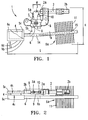
- Figures 1-5 show two embodiments 1,1' of an apparatus for detecting gas combustion in accordance with the invention, as an independent unit for installation in a free-standing environment heater or in a water heater.
- the detection apparatus 1 represented in figures 1-2 is made up of a single flat thermoelectric cell 4, while the apparatus represented in figures 3-4 comprises two flat cells 20, 21.
- a first preferred embodiment of the detection apparatus 1 comprises a support frame 8 for mounting the detection apparatus 1, an elongated burner 2 with a jet 2a that emits a pilot flame 3, an igniter 10 of the pilot flame 3, and a thermoelectric assembly (4-6) including a Peltier type thermoelectric cell 4 that operates by Seebeck effect, and formed by means of two flat sides parallel to each other, the hot side 4h and the cold side 4c, an element 5 for transmitting the heat from the pilot flame 3 to the thermoelectric cell 4, and a heat exchanger 6 for dissipating the heat from the cold side 4c of the cell to the environment.
- a thermoelectric assembly including a Peltier type thermoelectric cell 4 that operates by Seebeck effect, and formed by means of two flat sides parallel to each other, the hot side 4h and the cold side 4c, an element 5 for transmitting the heat from the pilot flame 3 to the thermoelectric cell 4, and a heat exchanger 6 for dissipating the heat from the cold side 4c of the cell to the environment.
- thermoelectric cell 4 By means of the heat transmitter element 5 connected to the hot side 4h of the cell and of the heat exchanger 6 connected to the cold side 4c, a temperature difference is maintained between the two opposite sides 4h and 4c of the cell, whereby the thermoelectric cell 4 generates an electric power of a dc voltage (FIG. 5) of , for instance, 1.5 V, with a current of 110 mA, which is supplied to an electric circuit in the temperature control system, not shown in the drawings.
- a dc voltage FOG. 5
- thermoelectric cell 4 is of a commercial type, consisting of a series of thermoelectric PN junctions, which takes the form of a thin flat plate and the two opposite sides 4h and 4c made of electrical insulating ceramic material, such as aluminium oxide, with dimensions of approximately 25 x 25 mm.
- the cell 4 is away from the pilot flame as its temperature resistance is limited to 250°C.
- the elongated transmitter element 5 is made of a metallic material that is a good heat conductor and has a thermal head 5a for the pilot flame 3, which reaches a flame temperature of around 700 °C.
- the thermal head 5a is heated directly by the pilot flame 3 for generating the electric power in the thermoelectric cell 4.
- the permanent heating of the thermal head 5a by the pilot flame 3 is also used for detecting oxygen depletion (ODS) in the ambient air, which causes the flame 3 to flicker or go out, by means of producing a voltage Vb (FIG. 5) generated for energizing a safety valve, which is of low value compared with a voltage Vd around 1,5 V -110 mA generated between the two ends of the cell 4, for supplying either a main valve with the heater main gas flow, or an appliance electronic unit.
- Cell 4 has two electric cable outputs 12,13 for supplying these two voltage values, Vd and Vb respectively, to the combustion control system.
- the heat transmitter element 5 also comprises an elongated transmitter member 5b, which is either integral with the thermal head 5a or welded to it, and a flat part 5c in contact with the hot side 4h of the cell.
- the latter has a larger area than cell 4, for instance 37 x 25 mm.
- the transmitter element 5 is supported along with the pilot burner 2 on the mounting frame 8, which is made of metal plate.
- the thermal head 5a of the transmitter element is attached to the frame 8 by means of a fastening clamp 9, opposite the burner jet 2a, and keeping a position relative to the length of the pilot flame 3.
- this relative position of the head 5a is set at a distance "e" separating the thermal head 5a from the burner jet 2a. This relative distance of the thermal head 5a also determines the rate of rise of the voltage Vb at output 13 generated by cell 4, when the pilot burner 2 is initially ignited.
- FIG. 5 also shows the decrease in the low voltage Vb at output 13 down to 50% of the load steady value, when the thermoelectric unit 1 has detected either a shortening of the pilot flame 3 due to oxygen depletion or the flame going out, in a time “td” of several seconds as of detection.
- This relative position "e" of the thermal head 5a is variable by moving the said clamp 9 attaching it to the installation frame 8.
- the pilot burner 2 is cylindrical in shape and extends in a horizontal direction like the flame emitted, secured in a fixed position on the installation frame 8, and in this way the pilot flame 3 emitted falls directly onto the thermal head 5a.
- the elongated burner 2 has a flame 3 emitting jet 2a and at the opposite end a gas supply connection 2b.
- the transmitter element 5 and the cell 4 extend in a direction opposite to that of the burner 2.
- the frame 8 also optionally supports an ignition spark electrode 10, which may be activated by the Vd voltage generated in the output 12.
- the detection apparatus 1 may also be used coupled to a water heater, provided that the thermal head 5a is interposed facing a burner nozzle or hole, and the generator unit support frame is adapted to this burner.
- the heat sink 6 connected to the cold side 4c of the thermoelectric cell may also be adapted to the base of a water heater.
- the intermediate member 5b of the transmitter element is preferably made of copper pipe filled with a good heat conducting fluid so that the temperature gradient between the thermal head 5a and the flat connecting part 5c to the cell 4 may be low.
- the transmitter tube 5b has a cross section adapted for the connection with the thermal head 5a.
- the heat exchange 6 consists of a heat sink 6a away from the thermoelectric cell 4 and the pilot flame 3, an exchanger conductor member 6b and a flat connecting part 6c to the cold side 4c of the cell, which has a larger area than the latter.
- the exchanger conductor member 6b is a copper tube filled with heat conductor fluid, of a diameter of 6 mm for example.
- the heat sink 6a is made up of a series of fins 11 welded onto a central body 15 joined to said conductor member 6b of the heat exchanger 6.
- the conductor member 6b may also be made of a flat copper conductor linked to a heat sink, the latter being made of a metallic profile.
- the support frame 8 and the pilot burner 2 extend in a horizontal direction when the detection apparatus 1 is installed in the heater, occupying between the two a space approximately 100 mm long.
- the thermoelectric cell 4 occupies a position set to one side of the frame 8.
- the heat exchanger 6 has an elongated shape and extends preferably horizontally from the thermoelectric cell 4 to the burner 2, in order that the heat sink 6a may be sited in a position away from the flame 3, without increasing the overall length "L" of the detection apparatus 1 so that it is compact.
- the burner 2 and the heat sink 6a are superimposed in a single space relative to the volume occupied by the detection apparatus 1.
- the conductor member 6b may be oriented at an angle of inclination "A" in relation to a central horizontal line 14 of cell 4, for example of 5 degrees, so that the extent of the heat sink fins 11 does not increase the total height "H” of the apparatus 1, limited in this way to 80 mm.
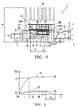
- a second preferred embodiment of the detection apparatus 1 is adapted as an independent unit for its installation on a free-standing environment heater or water heater, and the generation of a lower voltage Vb around 20 mV, 200 mA, for energizing a safety valve 16, and the generation also of a higher voltage Vd higher than 1.2 V for supplying the main valve 17 of the apparatus and the heater electronic unit, the latter not being shown in the drawings.
- the combustion detection apparatus 1' comprises the following items, mounted on a shared flat plate support 8': an elongated burner 2 with a jet 2a that emits a pilot flame 3, an igniter 10, and a thermoelectric assembly 20-26 which provides dc voltage outputs Vb and Vd, with this thermoelectric assembly 20-26 forming a compact unit with the burner 2 and the igniter 10 on the plate support 8'.
- the thermoelectric cells 20, 21 are protected against impacts and external forces by the actual natural convection heat sink 22, which surrounds them like a cover.
- the thermoelectric cell output terminals 28, 29 (FIG. 4) are also covered under the heat sink 22, and provided by soldering with two pairs of electrical connection wires for the solenoid valves.
- the burner 2, the igniter 10 and the heat sink 22 are supported directly on the flat support 8'.
- the thermoelectric assembly 20-26 comprises two flat cells 20, 21 of a different area, matching the voltage value Vb, Vd generated.
- the heat sink 22 is provided with two side support legs 22b attached to the base of the support 8' which form a recess in the heat sink 22 where the cells block 20,21 is installed, resting against a flat contact surface 22a of the heat sink.
- the thermoelectric block 20,21,25 is held against the heat sink 22 under pressure by means of a tensioned spring element, such as a spring leaf 23 attached to the igniter 10.
- the spring leaf 23 in turn offsets the dimensional deviations in the thickness of the cells 20,21, in the surrounding heat sink 22, and exerts a thermal contact of the larger cell 20 against the flat surface 22a of the heat sink.
- the smaller cell 21 overlaps the larger cell 20, with one side edge of both aligned, so that on the larger cell a part of its surface remains free to engage the spring leaf 23.
- thermoelectric assembly 20-26 is made up of two flat cells 20,21, each of them with a series of hot and cold p-n junctions between semiconductor elements, which are series and parallel-connected in combination to generate the desired voltage Vb, Vd.
- the PN junctions of each thermoelectric cell are soldered on a printed circuit between a pair of ceramic plates 20c, 20h, and 21c,21h, external and parallel to them, which are electrical insulators but good thermal conductors.
- Cells 20,21 may also be built with metallic outer plates coated with an insulating layer.
- FIG. 5 shows the generation of the DC voltage by the detection apparatus 1'.
- the larger area cell 20 generates the high voltage Vd of at least 1.2 V in the direction of the output 12, with a current of around 110 mA sufficient to operate a main gas valve 17 which actuates with a minimun value of 0.8 V and to supply the igniter 10 and the electronic unit of the appliance.
- the smaller area cell 21 generates the low voltage Vb of 20 mV open circuit and a current a current of up to 200 mA towards output 13 of the safety valve 16, whose electromagnet is approximately 17 milliohms.
- a current value generation time response is obtained in the smaller cell 21 greater than the 100 mA needed for the maintenance of the safety valve.
- Figures 3-4 show the two thermoelectric cells 20-21 superimposed and joined by means of a layer of soft solder 26.
- the free area of the smaller cell 21 thereby forms the hot side 21h, connected thermally by means of soft solder to a heat transmitter tube 25, the end of which has a thermal head 25a licked by the pilot flame 3.
- the hot 21h and cold 21c ceramic plates are interconnected internally by means of two side heat bridges in the form of copper bars 24 soldered on the internal faces of each cell plates 21h,21c, for transmitting the heat from the transmission tube 25 to the larger cell 20, so that this is heated too, and in turn for decreasing the safety valve 16 shut-off time when the flame 3 is extinguished.
- the heat transmission tube 25 is made straight and of a length "T" (FIG. 2) as short as possible, depending on the arrangement of the heat sink 22 on the burner 2 common support 8' so that the detection apparatus 1' may be compact. At the same time it is necessary to keep the cell 21 away from the pilot flame, as its temperature resistance is limited to 350°C. To take advantage of the heating power of the pilot flame 3, a flat hollow metal tube is preferred with a large contact area and filled with a fluid with good heat transmitting properties. Thus, the end of the tube 25 licked by the flame is heated to a temperature of around 700°C and the end soldered to the larger cell may reach a temperature of up to 200°C.
- the transmitter tube 25 is fly-supported by the thermoelectric cell block 20,21 and kept in a position matching the length of the pilot flame 3.
- this position of the thermal head 25a is set to a given separation distance "e'" from the burner jet 2a, in order to secure prompt cooling in the event of some deficiency occurring in the pilot flame 3.
- This relative position of the thermal head 25a is also adjusted to achieve a quick increase in the low voltage Vb generated by the smaller cell 21 after ignition.
- thermoelectric cells 20, 21 with an area of 33 x 23 mm and 23 x 11 mm, respectively.
- the width of the flat transmitter tube 25 is less than 8 mm and its length "T" approximately 50 mm.
- the heat sink 22 also has to have a longitudinal dimension "D" sufficient to cover the area of the cells 20,21 and their external connection terminals 28,29.
- the combustion detection apparatus 1' assembled in this way and shown in figures 3-4 does not exceed an overall length "L" of 60 mm.
Claims (9)
- Appareil destiné à la détection du gaz de combustion adapté à un appareil de chauffage à gaz domestique autonome ou à un chauffe-eau doté d'une soupape de sécurité (16), d'une soupape principale à gaz (17) et d'une unité de contrôle électronique, l'appareil de détection (1) comprenant,
un support de montage (8,8') qui assure le maintien de l'appareil de détection (1,1') et dont la forme lui permet d'être fixé sur l'appareil de chauffage à gaz ou le chauffe-eau,
un brûleur d'allumage (2) avec au moins une flamme pilote (3) en cas de défectuosité du système de détection du gaz de combustion et d'un dispositif d'allumage (10) incorporé au support de montage (8,8'),
un générateur thermoélectrique (4-6, 20-26) chauffé par la flamme pilote (3), qui fournit, par l'intermédiaire de deux sorties électriques (12, 13), une basse tension (Vb) pour alimenter l'électro-aimant de ladite soupape de sécurité (16) et pour détecter les carences du gaz de combustion de la flamme pilote (3) et une tension plus élevée (Vd) pour alimenter la soupape principale (17) et l'unité électronique de l'appareil de chauffage à gaz,
où l'ensemble thermoélectrique (4-6, 20-26) est incorporé sur ledit support de montage (8,8') formant ainsi une unité de montage compacte avec le brûleur pilote (2), caractérisé en ce que l'ensemble thermoélectrique (4-6, 20-26) comprend au moins une cellule thermoélectrique plate (4,20,21) composée d'une jonction P-N semiconductrice, avec deux faces latérales, l'une chaude et l'autre froide, qui ont la forme de plaques (4h,4c,21h,20c) écartées l'une de l'autre, un élément de transmission de la chaleur (5,25) caressé par la flamme pilote (3) et relié à la plaque chaude (4h,21h) et un échangeur de chaleur (6,22) connecté à la plaque froide (4c,20c). - Appareil de détection du gaz de combustion selon la revendication 1, où ledit élément de transmission de la chaleur (5,25) est formé d'une tête thermique (5a,25a) positionnée sur le support de montage (8) à une distance donnée (e) la séparant du brûleur pilote (2) pour la détection rapide de la flamme pilote (3), et avec un membre de transmission de la chaleur (5b,25) connecté à la tête thermique (5a,25a) séparant la cellule plate (4) ou les cellules plates (20,21) de la flamme (3).
- Appareil de détection du gaz de combustion selon la revendication 1, où l'ensemble thermoélectrique comprend une seule cellule plate (4) qui est déviée par l'élément de transmission de la chaleur (5) vers un côté du brûleur pilote (2), et l'échangeur de chaleur (6) est composé d'une pièce de connexion plate (6c) qui le relie à la cellule thermoélectrique (4), et un membre dissipateur de chaleur (6a) fixé sur la pièce plate (6c), qui s'étend dans la direction de l'espace (H,L) situé en dessous du support de montage de l'appareil (8).
- Appareil de détection du gaz de combustion selon la revendication 1, où l'ensemble thermoélectrique (20-26) qui est incorporé sur ledit support de montage (8') comprend deux cellules thermoélectriques plates (20,21) chacune étant composée de jonctions p-n semi-conductrices et doté de l'une desdites sorties électriques (13,12), et le dissipateur de chaleur (22) vers l'environnement forme un chemin thermique (25,21,20,22) partagé par les cellules thermoélectriques (20,21) et des moyens de connexion thermiques (24,26) entre les deux cellules (20,21).
- Appareil de détection du gaz de combustion selon la revendication 4, où les deux cellules thermoélectriques susmentionnées (20,21) présentent des surfaces différentes, l'une étant plus grande et l'autre plus petite, et dont les côtés chaud et froid sont composés de plaques isolantes plates (20c-21h), et les deux cellules (20,21) se chevauchent et sont en contact thermique l'une avec l'autre, formant ainsi ledit chemin thermique partagé (25,21,20,22) entre ledit élément de transmission de la chaleur (25) relié à la plaque chaude (21h) de la cellule de plus petite taille (21), et ledit dissipateur de chaleur (22) connecté à la plaque froide (20c) de la cellule plus grande (20).
- Appareil de détection du gaz de combustion selon la revendication 4, où les cellules thermoélectriques (20,21) présentent des surfaces différentes, l'une étant plus grande et l'autre plus petite, se chevauchent, et sont connectées thermiquement l'une à l'autre avec une extrémité latérale alignée, alors qu'une partie de la cellule plus grande (20) reste libre pour la prise, sous tension, d'un élément de ressort (23), qui sécurise les deux cellules (20,21) contre le dissipateur de chaleur (22).
- Appareil de détection du gaz de combustion selon la revendication 4, où les deux cellules thermoélectriques plates (20,21) sont chacune composées de deux plaques isolantes extérieures (20c-21h) parallèles l'une à l'autre, et ledit moyen de connexion thermique (24,26) des deux cellules (20,21) pour la transmission de la chaleur entre elles comprend une couche de connexion thermique (26) entre deux plaques superposées (20h,21c) des deux cellules et au moins un pont thermique qui a la forme d'une barre de cuivre (24) construit dans l'une des cellules (21) pour la transmission directe d'une partie de la chaleur reçue par cette cellule (21) vers l'autre cellule (20).
- Appareil de détection de gaz de combustion selon la revendication 4, où le dissipateur de chaleur (22) est métallique et doté d'ailettes de ventilation naturelles, et de deux jambes latérales (22b) pour pouvoir être fixé sur le support de montage (8') de l'appareil de détection, ledit dissipateur de chaleur (22) formant une enceinte compacte pour installer et couvrir les deux cellules thermoélectriques (20,21) qui se chevauchent.
- Appareil de détection de gaz de combustion selon la revendication 4, où ledit élément de transmission de la chaleur (25) est doté, à une extrémité, d'une tête thermique (25a) caressée par la flamme pilote (3) et est positionné à une distance de séparation donnée (e') du gicleur du brûleur pilote (2a) pour le chauffage rapide de la cellule plus petite (21) et pour la détection des carences de gaz de combustion.
Applications Claiming Priority (4)
| Application Number | Priority Date | Filing Date | Title |
|---|---|---|---|
| ES200202601 | 2002-11-13 | ||
| ES200202601 | 2002-11-13 | ||
| ES200302421 | 2003-10-17 | ||
| ES200302421 | 2003-10-17 |
Publications (2)
| Publication Number | Publication Date |
|---|---|
| EP1420206A1 EP1420206A1 (fr) | 2004-05-19 |
| EP1420206B1 true EP1420206B1 (fr) | 2007-07-18 |
Family
ID=32178789
Family Applications (1)
| Application Number | Title | Priority Date | Filing Date |
|---|---|---|---|
| EP20030380257 Expired - Fee Related EP1420206B1 (fr) | 2002-11-13 | 2003-11-05 | Dispositif de détection de la combustion avec un générateur thermoélectrique |
Country Status (3)
| Country | Link |
|---|---|
| US (1) | US7018200B2 (fr) |
| EP (1) | EP1420206B1 (fr) |
| ES (1) | ES2287436T3 (fr) |
Cited By (1)
| Publication number | Priority date | Publication date | Assignee | Title |
|---|---|---|---|---|
| US7992670B2 (en) | 2006-02-28 | 2011-08-09 | Bayerische Motoren Werke Aktiengensellschaft | Motor vehicle having a unit operated by a cryogenically stored fuel |
Families Citing this family (26)
| Publication number | Priority date | Publication date | Assignee | Title |
|---|---|---|---|---|
| US8863736B2 (en) * | 1999-12-06 | 2014-10-21 | Enerco Group, Inc. | Gas-fired heater with environmental detector |
| US11841159B2 (en) | 2002-03-06 | 2023-12-12 | John Chris Karamanos | Embedded heat exchanger with support mechanism |
| US20060016446A1 (en) * | 2004-07-24 | 2006-01-26 | Hu Caroline K | Gas stove with thermoelectric generator |
| US20060172245A1 (en) * | 2005-01-31 | 2006-08-03 | Hu Caroline K | Gas burner with thermoelectric generator |
| DE102006009081A1 (de) * | 2006-02-28 | 2007-08-30 | Bayerische Motoren Werke Ag | Vorrichtung zum Umwandeln des Boil-Off-Gases eines Kryo-Kraftstofftanks |
| US20070221205A1 (en) * | 2006-03-21 | 2007-09-27 | Landon Richard B | Self powered pelletized fuel heating device |
| DE102006040854A1 (de) * | 2006-08-31 | 2008-03-20 | Siemens Ag | Thermoelektrische Einrichtung mit einem thermoelektrischen Generator und einem thermischen Widerstand sowie Verwendung einer solchen Einrichtung |
| WO2008086489A2 (fr) * | 2007-01-10 | 2008-07-17 | Karamanos John C | Échangeur thermique incorporé pour systèmes et procédés de chauffage, de ventilation et de climatisation (hvac) |
| US8403661B2 (en) | 2007-03-09 | 2013-03-26 | Coprecitec, S.L. | Dual fuel heater |
| US8057219B1 (en) | 2007-03-09 | 2011-11-15 | Coprecitec, S.L. | Dual fuel vent free gas heater |
| US8118590B1 (en) | 2007-03-09 | 2012-02-21 | Coprecitec, S.L. | Dual fuel vent free gas heater |
| US7766006B1 (en) | 2007-03-09 | 2010-08-03 | Coprecitec, S.L. | Dual fuel vent free gas heater |
| ES1067938Y (es) * | 2008-05-12 | 2008-10-16 | Coprecitec Sl | Quemador de llama piloto con detector de empobrecimiento de oxigeno |
| US8453456B2 (en) * | 2009-03-25 | 2013-06-04 | United Technologies Corporation | Fuel-cooled flexible heat exchanger with thermoelectric device compression |
| US8522560B2 (en) * | 2009-03-25 | 2013-09-03 | United Technologies Corporation | Fuel-cooled heat exchanger with thermoelectric device compression |
| US8684276B2 (en) * | 2009-08-20 | 2014-04-01 | Enerco Group, Inc. | Portable catalytic heater |
| US8899971B2 (en) | 2010-08-20 | 2014-12-02 | Coprecitec, S.L. | Dual fuel gas heater |
| MX2014010138A (es) * | 2012-02-22 | 2016-03-04 | Clearsign Comb Corp | Electrodo refrigerado y sistema quemador que incluye un electrodo refrigerado. |
| CN103401478A (zh) * | 2013-07-31 | 2013-11-20 | 重庆大学 | 一种燃气燃烧热发电与供电的装置 |
| US9920930B2 (en) * | 2015-04-17 | 2018-03-20 | Honeywell International Inc. | Thermopile assembly with heat sink |
| US10478016B2 (en) * | 2015-06-08 | 2019-11-19 | Masterbuilt Manufacturing, Inc. | Gas-fired smoker with digital temperature control |
| US10151482B2 (en) | 2015-06-24 | 2018-12-11 | Dexen Industries, Inc. | System for igniting and controlling a gas burning appliance |
| ITUB20152265A1 (it) * | 2015-07-17 | 2017-01-17 | Eltek Spa | Dispositivo per la gestione di apparecchi a gas, e relativi sistemi e metodi |
| US10422530B2 (en) * | 2016-10-27 | 2019-09-24 | Reecon M & E Co. Ltd. | Smart fuel burning system and method of operating same |
| US11885494B2 (en) * | 2016-10-27 | 2024-01-30 | Reecon North America LLC | Smart fuel burning system and method of operating same |
| US20210278143A1 (en) * | 2020-03-09 | 2021-09-09 | Carrier Corporation | System and method for capturing waste heat in an hvac system |
Family Cites Families (11)
| Publication number | Priority date | Publication date | Assignee | Title |
|---|---|---|---|---|
| DE1065901B (de) * | 1954-10-15 | 1959-09-24 | Robertshaw-Fulton Controls Company, Greensburg, Pa. (V. St. A.) | Thermoelement für einen Zündbrenner |
| US2821564A (en) * | 1956-05-17 | 1958-01-28 | Baso Inc | Thermoelectric generator and pilot burner |
| US3017445A (en) * | 1959-07-07 | 1962-01-16 | Minnesota Mining & Mfg | Burner-thermoelectric generator assembly |
| US3441450A (en) * | 1964-04-27 | 1969-04-29 | Honeywell Inc | Thermoelectric generator including a pilot burner |
| ES8405127A1 (es) * | 1982-08-03 | 1984-06-01 | Stefani & C G Pernumia | Perfeccionamientos en los dispositivos de seguridad para aparatos de calentamiento por gas |
| US4734139A (en) * | 1986-01-21 | 1988-03-29 | Omnimax Energy Corp. | Thermoelectric generator |
| FR2614385B1 (fr) * | 1987-04-24 | 1989-07-28 | Chaffoteaux Et Maury | Perfectionnements aux dispositifs de securite pour vannes a gaz |
| US5427086A (en) * | 1993-07-26 | 1995-06-27 | Rochester Gas And Electric Co. | Forced air furnace having a thermoelectric generator for providing continuous operation during an electric power outage |
| US5674065A (en) * | 1996-01-22 | 1997-10-07 | Op S.R.L. | Apparatus for controlling the supply of gas to and heat from unvented gas heating appliances |
| WO2000050815A1 (fr) * | 1999-02-26 | 2000-08-31 | Robertshaw Controls Company | Sonde d'oxygene a niveaux |
| US20050037303A1 (en) * | 2003-08-15 | 2005-02-17 | Bachinski Thomas J. | Generation of electricity in a fireplace using thermoelectric module |
-
2003
- 2003-11-05 EP EP20030380257 patent/EP1420206B1/fr not_active Expired - Fee Related
- 2003-11-05 ES ES03380257T patent/ES2287436T3/es not_active Expired - Lifetime
- 2003-11-10 US US10/705,382 patent/US7018200B2/en not_active Expired - Fee Related
Cited By (1)
| Publication number | Priority date | Publication date | Assignee | Title |
|---|---|---|---|---|
| US7992670B2 (en) | 2006-02-28 | 2011-08-09 | Bayerische Motoren Werke Aktiengensellschaft | Motor vehicle having a unit operated by a cryogenically stored fuel |
Also Published As
| Publication number | Publication date |
|---|---|
| US7018200B2 (en) | 2006-03-28 |
| US20040096790A1 (en) | 2004-05-20 |
| ES2287436T3 (es) | 2007-12-16 |
| EP1420206A1 (fr) | 2004-05-19 |
Similar Documents
| Publication | Publication Date | Title |
|---|---|---|
| EP1420206B1 (fr) | Dispositif de détection de la combustion avec un générateur thermoélectrique | |
| US4208570A (en) | Thermostatically controlled electric engine coolant heater | |
| RU2386906C1 (ru) | Регулирующая насадка для клапанов теплообменников, в частности терморегулирующая насадка для радиаторных клапанов | |
| US20060016446A1 (en) | Gas stove with thermoelectric generator | |
| CA2613300C (fr) | Dispositif de chauffage a dispositif thermoelectrique | |
| US6732677B2 (en) | Bracket for water heater | |
| JPH1155974A (ja) | 熱発電ユニット | |
| JPH1155975A (ja) | 熱発電装置 | |
| US6717044B2 (en) | Thermopile construction with multiple EMF outputs | |
| JP3516225B2 (ja) | 熱電変換器を備えるアルコール・ストーブ | |
| US7256344B2 (en) | Electrothermal device for ignition and flame detection in gas burners | |
| KR20080017042A (ko) | 열전 모듈을 포함하는 가열장치 | |
| JPH09184771A (ja) | 給湯器の過熱検知用センサ | |
| CN208579332U (zh) | 气源自动识别控制装置 | |
| KR20220070856A (ko) | 고효율 열전발전모듈 | |
| US6740806B2 (en) | Combined thermocouple and thermopile capable of generating multiple EMF signals | |
| PL189989B1 (pl) | Urządzenie do ograniczania temperatury gazowego zaspołu grzejnego do gotowania | |
| US2891610A (en) | Burner control system having opposing thermoelectric generators | |
| US5645411A (en) | Radiation gas burner with safety device | |
| AU2017202731A1 (en) | Improvements in Water Heating Elements | |
| US2592952A (en) | Thermoelectric control system | |
| JPH05126410A (ja) | 給湯機用制御回路板の冷却装置 | |
| US20210054999A1 (en) | Thermally-actuated gas valve with ceramic heater | |
| KR200389238Y1 (ko) | 정온도계수 써미스터를 이용한 온도보상용 히터 | |
| KR100579439B1 (ko) | 정온도계수 써미스터를 이용한 온수히터 |
Legal Events
| Date | Code | Title | Description |
|---|---|---|---|
| PUAI | Public reference made under article 153(3) epc to a published international application that has entered the european phase |
Free format text: ORIGINAL CODE: 0009012 |
|
| AK | Designated contracting states |
Kind code of ref document: A1 Designated state(s): AT BE BG CH CY CZ DE DK EE ES FI FR GB GR HU IE IT LI LU MC NL PT RO SE SI SK TR |
|
| AX | Request for extension of the european patent |
Extension state: AL LT LV MK |
|
| 17P | Request for examination filed |
Effective date: 20040616 |
|
| AKX | Designation fees paid |
Designated state(s): ES GB IT |
|
| REG | Reference to a national code |
Ref country code: DE Ref legal event code: 8566 |
|
| RAP1 | Party data changed (applicant data changed or rights of an application transferred) |
Owner name: COPRECITEC, S.L. |
|
| GRAP | Despatch of communication of intention to grant a patent |
Free format text: ORIGINAL CODE: EPIDOSNIGR1 |
|
| GRAS | Grant fee paid |
Free format text: ORIGINAL CODE: EPIDOSNIGR3 |
|
| GRAA | (expected) grant |
Free format text: ORIGINAL CODE: 0009210 |
|
| AK | Designated contracting states |
Kind code of ref document: B1 Designated state(s): ES GB IT |
|
| REG | Reference to a national code |
Ref country code: GB Ref legal event code: FG4D |
|
| REG | Reference to a national code |
Ref country code: ES Ref legal event code: FG2A Ref document number: 2287436 Country of ref document: ES Kind code of ref document: T3 |
|
| PLBE | No opposition filed within time limit |
Free format text: ORIGINAL CODE: 0009261 |
|
| STAA | Information on the status of an ep patent application or granted ep patent |
Free format text: STATUS: NO OPPOSITION FILED WITHIN TIME LIMIT |
|
| 26N | No opposition filed |
Effective date: 20080421 |
|
| PG25 | Lapsed in a contracting state [announced via postgrant information from national office to epo] |
Ref country code: IT Free format text: LAPSE BECAUSE OF NON-PAYMENT OF DUE FEES Effective date: 20071130 |
|
| PGFP | Annual fee paid to national office [announced via postgrant information from national office to epo] |
Ref country code: GB Payment date: 20131120 Year of fee payment: 11 |
|
| PGFP | Annual fee paid to national office [announced via postgrant information from national office to epo] |
Ref country code: ES Payment date: 20131119 Year of fee payment: 11 |
|
| GBPC | Gb: european patent ceased through non-payment of renewal fee |
Effective date: 20141105 |
|
| PG25 | Lapsed in a contracting state [announced via postgrant information from national office to epo] |
Ref country code: GB Free format text: LAPSE BECAUSE OF NON-PAYMENT OF DUE FEES Effective date: 20141105 |
|
| REG | Reference to a national code |
Ref country code: ES Ref legal event code: FD2A Effective date: 20151229 |
|
| PG25 | Lapsed in a contracting state [announced via postgrant information from national office to epo] |
Ref country code: ES Free format text: LAPSE BECAUSE OF NON-PAYMENT OF DUE FEES Effective date: 20141106 |