EP1420203A1 - Support de carter pour moteur de véhicule automobile - Google Patents
Support de carter pour moteur de véhicule automobile Download PDFInfo
- Publication number
- EP1420203A1 EP1420203A1 EP03292783A EP03292783A EP1420203A1 EP 1420203 A1 EP1420203 A1 EP 1420203A1 EP 03292783 A EP03292783 A EP 03292783A EP 03292783 A EP03292783 A EP 03292783A EP 1420203 A1 EP1420203 A1 EP 1420203A1
- Authority
- EP
- European Patent Office
- Prior art keywords
- support
- face
- casing
- housing
- elements
- Prior art date
- Legal status (The legal status is an assumption and is not a legal conclusion. Google has not performed a legal analysis and makes no representation as to the accuracy of the status listed.)
- Granted
Links
Images

Classifications
-
- F—MECHANICAL ENGINEERING; LIGHTING; HEATING; WEAPONS; BLASTING
- F16—ENGINEERING ELEMENTS AND UNITS; GENERAL MEASURES FOR PRODUCING AND MAINTAINING EFFECTIVE FUNCTIONING OF MACHINES OR INSTALLATIONS; THERMAL INSULATION IN GENERAL
- F16M—FRAMES, CASINGS OR BEDS OF ENGINES, MACHINES OR APPARATUS, NOT SPECIFIC TO ENGINES, MACHINES OR APPARATUS PROVIDED FOR ELSEWHERE; STANDS; SUPPORTS
- F16M11/00—Stands or trestles as supports for apparatus or articles placed thereon ; Stands for scientific apparatus such as gravitational force meters
- F16M11/20—Undercarriages with or without wheels
- F16M11/22—Undercarriages with or without wheels with approximately constant height, e.g. with constant length of column or of legs
-
- F—MECHANICAL ENGINEERING; LIGHTING; HEATING; WEAPONS; BLASTING
- F16—ENGINEERING ELEMENTS AND UNITS; GENERAL MEASURES FOR PRODUCING AND MAINTAINING EFFECTIVE FUNCTIONING OF MACHINES OR INSTALLATIONS; THERMAL INSULATION IN GENERAL
- F16M—FRAMES, CASINGS OR BEDS OF ENGINES, MACHINES OR APPARATUS, NOT SPECIFIC TO ENGINES, MACHINES OR APPARATUS PROVIDED FOR ELSEWHERE; STANDS; SUPPORTS
- F16M11/00—Stands or trestles as supports for apparatus or articles placed thereon ; Stands for scientific apparatus such as gravitational force meters
- F16M11/02—Heads
- F16M11/04—Means for attachment of apparatus; Means allowing adjustment of the apparatus relatively to the stand
- F16M11/041—Allowing quick release of the apparatus
Definitions
- the invention relates to a crankcase support for a motor vehicle.
- Engine housings generally include a body for receive the engine and a front panel located on the side of the coupling the gearbox to the engine.
- the shape of a housing varies for each family of engines. Furthermore, in a particular family of engines, the shape of the front face of the housing may vary depending on the type coupling used between the gearbox and the engine. It exists therefore a large number of casings of different shapes, which implies an equally large number of crankcase supports.
- the known housing supports are generally molded of a piece of rigid material, and have a relatively weight high in order to be able to support the weight of the motor, about 150 kg, and that of the gearbox, about 50 kg. Their weight is close thus often 5 kg and their repetitive movement generates fatigue important for the operator.
- the invention aims to remedy these drawbacks by proposing a housing support which can be used for corresponding housings to one or more engine families. Support changes thus reduced significantly by the operator, which saves time and reduces operator fatigue.
- the object of the invention relates to a housing support for motor, said casing comprising a body intended to receive the engine and a front panel located on the side of the engine coupling to the gearbox, said support comprising a plurality of points support to support the housing body.
- the support is characterized by what it includes a plurality of front support elements, each face support element being able to cooperate with and support the front face of a predetermined casing separate from the other casing (s) predetermined, and in that the plurality of support points is suitable for support the bodies of the various predetermined housings.
- the same support can thus be used for different casings having the same support points but different faces. It is enough then choose the appropriate face support element. This last having dimensions and a low weight compared to the support crankcase as a whole, operator comfort can be improved.
- the invention is also economically advantageous when the production of new housings that can be supported by same support points. It is no longer necessary to manufacture new supports, but only new support elements front.
- the support comprises at at least one fixed face support element and at least one support element mobile face.
- each of the movable face support elements is movable between a position of use, in which it supports the front face of the predetermined casing with which it cooperates, and a position rest in which another fixed or movable face support element supports the front face of another predetermined casing with which it cooperates.
- This rest position can be located on the support or at distance from it.
- the movable face support elements comprise means for fixing and / or blocking on said support crankcase.
- the front support elements mobile are articulated to the housing support around an axis of rotation fixed relative to the support. The operator then no longer needs to move to change the appropriate parts, just place the support element corresponding to the motor housing in position use.
- the movable face support elements can have oblong holes for the passage of the axis of rotation.
- the support elements of mobile sides can rest on the housing support, and oblong holes can be located so that, in the use position, the axis of rotation passes through the oblong holes at their distal end of the housing support, and that when the support element is rotated removable, the axis of rotation passes through the oblong holes at their end opposite.
- the oblong holes thus participate in blocking the element front support in use position.
- the blocking means consist of surfaces of the housing support bearing against at least a portion of the surface of the movable face support element in the position of use and in forms of the housing support cooperating with complementary shapes of said support element in the position of use.
- the front support elements mobile are fixed on a removable part of the housing support. The operator can then easily replace the removable part in case wear of the latter, or to set up another part removable comprising front support elements cooperating with other housings.
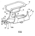
- the support 10 is intended to support a motor casing 12.
- the casing 12 comprises a body 14 intended to support the motor (not shown) and a front face 16 located on the side of the coupling between the engine and the gearbox, when the engine is in the housing.
- the support 10 has a flat base plate 20 and substantially rectangular on which the support 10 will rest.
- Each fulcrum 22 includes, at a distance from the base plate 20, an upper end 24 intended to support the body 14 of the casing 12. These ends 24 are generally in contact with housing screws 12, they must therefore be particularly resistant. To this end, provision can be made for them reinforce with a metal part (not shown) on which the screw will be in contact. We can for example use a metal washer put in place when the support 10.
- the number of support points 22 must be sufficient to prevent motor tilting.
- the shape and location of these points support 22 are chosen so that they can support the bodies 14 from different housings 12.
- the base plate 20 includes a removable part 26 at one of its ends, on which face support elements are located described below.
- This removable part 26 is, for example, fixed on the base plate 20 by means of screws (not shown). These screws are introduced into bores 28 of the removable part 26 and corresponding bores (not shown) of the base plate 20. These bores extend in the plane of the base plate 20.
- a step 29a made in the thickness of the edge of the removable part 26 coming into contact with a complementary offset 29b produced in the corresponding edge of the plate 20 facilitates the centering and positioning of the removable part 26.
- other fixing means can be used between the base plate 20 and its removable part 26.
- the support 10 also includes several support elements from the front 30, 32, 34, each of these elements cooperating with and supporting a front face 16 of a predetermined casing 12.
- the support 10 can thus be used for three different casings 12 corresponding each to a face support element 30, 32, 34. These are shown for clarity not fixed in Figure 2.
- a support element is permanently connected to the support and is movable between a position of use, in which it maintains the face of the housing, and a retracted position, in which it is not used.
- One 30 of these face support elements is fixed and integral with the edge of the removable portion 26 distal of the base plate 20. It extends along a plane substantially perpendicular to the plane of the plate base 20.
- This element 30 is for example in the form of a plate 36, substantially vertical, having an upper surface substantially flat 38 intended to cooperate with the front face 16 of the corresponding housing.
- the other face support elements 32 and 34 are movable by articulation around an axis of rotation 40.
- This axis 40 is fixed on the removable part 26 by axis support elements 42, for example at number three.
- the elements 40 are distributed along the plate 36 of the fixed face support element 30, so that the axis 40 extends in a direction parallel to the plane of the plate 36 and parallel to the base plate plan 20.
- the movable face support elements 32 and 34 are presented in the form of plates 44 and 46 respectively, of polygonal shape.
- these plates 44, 46 extend perpendicular to the plane of the base plate 20 and parallel to the fixed face support element 30. In this vertical position, defines for each plate 44, 46, an internal lateral face 41, 43 respectively, directed towards the center of the support 10 and a lateral face external 45, 47 respectively, on the side opposite the internal lateral face, a lower face 48, 49 respectively, located opposite the face upper 21 of the base plate 20, and an upper face 50, 51 respectively, on the side opposite the underside.
- the upper faces 50, 51 are provided to cooperate with and supporting the front face of the respective casings of the elements 32, 34.
- the front support elements mobiles 32, 34 cannot tilt around the axis 40, their lateral face external being partially supported on the fixed face support element 30.
- the angle between the external lateral surface 45, 47 and the surface lower 48, 49 of the support elements 32, 34 can be rounded so to facilitate their rotation between the rest and use positions.
- each of the movable face support elements 32, 34 can present on its external lateral face 45, 47 respectively, a part 54 projecting capable of cooperating with the removable part 26. It is, as shown for example in Figure 2 for element 32, of a surface 54 extending parallel to the external surface 45, at a distance from this last, so as to form a groove directed towards and form complementary to the upper part 56 of the face support element fixed 30. The latter can then be fitted into the next groove the direction perpendicular to the base plate 20.
- one of the support elements mobile face 34 has dimensions greater than the other mobile face support element 32.
- the element face support 32 has a shape which can be built into the element movable face support 34.
- part of the lower surface 49 of this the latter is supported on the upper surface 50 of the support element face 32.
- the face support element 34 can thus support without weakness high vertical pressure.
- the movable face support elements 32 and 34 are then folded against the upper face 21 of the plate base 20 so as not to hinder the installation of the casing.
- the housing support 10 described above can be produced in one resistant molded material.
- the base plate 20 and the support points 22 are molded in one block, the removable part 26 with the support element fixed face 30 and the axle supports 42 are molded in a block, each movable face support elements 32, 34 being molded separately.
- the movable face support elements can, in rest position, be folded down on the opposite side to that shown in the above embodiment. You just have to move the axis of outward rotation 40 of the support 10 on the other side of the support fixed face 30, the locking and holding means then being arranged preferably on the internal lateral face 41, 43 of the support elements front 32, 34.
- the support 10 then preferably has surfaces or means allowing these elements to be locked in the use position.
- the base plate 20 of the support does not have a removable part, only the elements front supports being mobile.
- the support points 22 are removable, for example snapped into the base plate 20. It is then possible to change them when casings with points support 22 different must be supported successively.
Landscapes
- Engineering & Computer Science (AREA)
- General Engineering & Computer Science (AREA)
- Mechanical Engineering (AREA)
- Cylinder Crankcases Of Internal Combustion Engines (AREA)
- Pivots And Pivotal Connections (AREA)
- Fittings On The Vehicle Exterior For Carrying Loads, And Devices For Holding Or Mounting Articles (AREA)
- Body Structure For Vehicles (AREA)
- Motorcycle And Bicycle Frame (AREA)
Abstract
Description
- la figure 1 est une vue en perspective d'un mode de réalisation d'un support de carter selon l'invention ;
- la figure 2 est une vue en perspective éclatée des éléments supports de face du mode de réalisation représenté figure 1.
- une partie de leur surface latérale externe 45, 47 soit en contact avec la surface latérale 37 en regard de l'élément support de face fixe 30 qui sert alors de butée,
- leurs surfaces inférieures 48, 49 soient en contact avec et reposent sur la face supérieure 21 de la partie amovible 26.
- en position d'utilisation, l'axe de rotation 40 traverse les trous oblongs à leur extrémité 52a distale de la partie amovible 26,
- lors de là rotation des éléments supports mobiles 32, 34, et dans leur position de repos, l'axe de rotation 40 soit situé à l'extrémité 52b opposée des trous oblongs.
Claims (9)
- Support (10) de carter pour moteur, ledit carter (12) comprenant un corps (14) destiné à recevoir le moteur et une face avant (16) située du côté de l'accouplement du moteur à la boíte de vitesse, ledit support (10) comprenant une pluralité de points d'appui (22) pour soutenir le corps (14) du carter, comprenant une pluralité d'éléments supports de face (30, 32, 34), chaque élément support de face étant apte à coopérer avec et à supporter la face avant (16) d'un carter prédéterminé distinct du ou des autres carters prédéterminés, la pluralité de points d'appui (22) étant apte à supporter les corps (14) des différents carters prédéterminés,
caractérisé en ce qu'il comprend au moins un élément support de face fixe (30) et au moins un élément support de face mobile (32, 34), et en ce que les éléments supports de face mobiles (32, 34) sont articulés au support (10) de carter autour d'un axe de rotation (40) fixe par rapport au support (10). - Support selon la revendication 1, caractérisé en ce que chaque élément support de face mobile (32, 34) est mobile entre une position d'utilisation, dans laquelle il supporte la face avant (16) du carter prédéterminé avec lequel il coopère, et une position de repos dans laquelle un autre élément support de face fixe (30) ou mobile (34, 32) supporte la face avant (16) d'un autre carter prédéterminé avec lequel il coopère.
- Support selon l'une des revendications 1 ou 2, caractérisé en ce que les éléments supports de face mobiles (32, 34) comprennent des moyens de fixation et/ou de blocage sur ledit support (10) de carter.
- Support selon l'une des revendications 1 à 3, caractérisé en ce que les éléments supports de face mobiles (32, 34) comportent des trous oblongs (52) pour le passage de l'axe de rotation (40).
- Support selon la revendication 4, caractérisé en ce que, en position d'utilisation, les éléments supports de face mobiles (32, 34) prennent appui sur le support (10) de carter, et en ce que les trous oblongs (52) sont situés de sorte que, en position d'utilisation, l'axe de rotation (40) traverse les trous oblongs (52) à leur extrémité (52a) distale du support (10) de carter, et que, lors de la rotation de l'élément support de face mobile (32, 34), l'axe de rotation (40) traverse les trous oblongs (52) à leur extrémité (52b) opposée.
- Support selon l'une des revendications 3 à 5, caractérisé en ce que les moyens de blocage consistent en des surfaces du support (10) de carter en appui contre au moins une partie de la surface de l'élément support de face mobile (32, 34) dans la position d'utilisation et en des formes du support (10) de carter coopérant avec des formes complémentaires dudit élément support de face (32, 34) en position d'utilisation.
- Support selon l'une des revendications 1 à 6, caractérisé en ce que les éléments supports de face (30, 32, 34) sont fixés sur une partie amovible (26) du support (10) de carter.
- Support selon les revendications 1 à 6, caractérisé en ce qu'au moins un élément de support de face est relié en permanence au support et est mobile entre une position d'utilisation et une position escamotée dans laquelle il ne sert pas.
- Support selon l'une des revendications 1 à 7, caractérisé en ce que les extrémités (24) des points d'appui (22) en contact avec le carter sont renforcées par une pièce métallique.
Applications Claiming Priority (2)
| Application Number | Priority Date | Filing Date | Title |
|---|---|---|---|
| FR0214172 | 2002-11-13 | ||
| FR0214172A FR2847022B1 (fr) | 2002-11-13 | 2002-11-13 | Support de carter pour moteur de vehicule automobile |
Publications (2)
| Publication Number | Publication Date |
|---|---|
| EP1420203A1 true EP1420203A1 (fr) | 2004-05-19 |
| EP1420203B1 EP1420203B1 (fr) | 2006-11-02 |
Family
ID=32116576
Family Applications (1)
| Application Number | Title | Priority Date | Filing Date |
|---|---|---|---|
| EP03292783A Expired - Lifetime EP1420203B1 (fr) | 2002-11-13 | 2003-11-06 | Support de carter pour moteur de véhicule automobile |
Country Status (4)
| Country | Link |
|---|---|
| EP (1) | EP1420203B1 (fr) |
| DE (1) | DE60309415T2 (fr) |
| ES (1) | ES2271501T3 (fr) |
| FR (1) | FR2847022B1 (fr) |
Citations (4)
| Publication number | Priority date | Publication date | Assignee | Title |
|---|---|---|---|---|
| GB680564A (en) * | 1950-01-31 | 1952-10-08 | Cyril Richmond Hughes | Improved means for supporting dismounted engines of motor vehicles |
| US3306601A (en) * | 1964-10-06 | 1967-02-28 | Jack E Mitchell | Transmission stand |
| US4138079A (en) * | 1977-10-12 | 1979-02-06 | Wylain, Inc. | Motor supporting platform |
| US4809963A (en) * | 1987-06-23 | 1989-03-07 | Kelly Thomas J | Adjustable engine stand |
-
2002
- 2002-11-13 FR FR0214172A patent/FR2847022B1/fr not_active Expired - Fee Related
-
2003
- 2003-11-06 ES ES03292783T patent/ES2271501T3/es not_active Expired - Lifetime
- 2003-11-06 DE DE60309415T patent/DE60309415T2/de not_active Expired - Lifetime
- 2003-11-06 EP EP03292783A patent/EP1420203B1/fr not_active Expired - Lifetime
Patent Citations (4)
| Publication number | Priority date | Publication date | Assignee | Title |
|---|---|---|---|---|
| GB680564A (en) * | 1950-01-31 | 1952-10-08 | Cyril Richmond Hughes | Improved means for supporting dismounted engines of motor vehicles |
| US3306601A (en) * | 1964-10-06 | 1967-02-28 | Jack E Mitchell | Transmission stand |
| US4138079A (en) * | 1977-10-12 | 1979-02-06 | Wylain, Inc. | Motor supporting platform |
| US4809963A (en) * | 1987-06-23 | 1989-03-07 | Kelly Thomas J | Adjustable engine stand |
Also Published As
| Publication number | Publication date |
|---|---|
| FR2847022B1 (fr) | 2005-05-27 |
| DE60309415D1 (de) | 2006-12-14 |
| EP1420203B1 (fr) | 2006-11-02 |
| DE60309415T2 (de) | 2007-09-20 |
| FR2847022A1 (fr) | 2004-05-14 |
| ES2271501T3 (es) | 2007-04-16 |
Similar Documents
| Publication | Publication Date | Title |
|---|---|---|
| FR2600726A2 (fr) | Dispositif d'assemblage d'ossature de stand pour exposition temporaire. | |
| FR2809684A1 (fr) | Accoudoir escamotable | |
| EP1364834B1 (fr) | Dispositif pour retenir et articuler une tablette arrière amovible de véhicule automobile | |
| WO2009024696A1 (fr) | Structure comportant des organes articules pour le support de la caisse d'un vehicule automobile | |
| FR2845460A1 (fr) | Projecteur d'eclairage de vehicule automobile comportant un element d'articulation en appui sur le boitier | |
| EP4304901B1 (fr) | Dispositif de support du chargeur de batterie des vehicules automobiles | |
| FR2781017A1 (fr) | Dispositif de fixation pour un composant reglable et devant etre bloque par serrage | |
| EP0412908A1 (fr) | Tourillon d'axe de site pour affût d'armement | |
| EP1420203B1 (fr) | Support de carter pour moteur de véhicule automobile | |
| FR2626802A1 (fr) | Table a bombe reglable pour presse plieuse, marbre ou autre similaire | |
| EP1911624A2 (fr) | Systeme de montage amovible d'un premier élément sur un second élément, notamment pour une assise arrière de véhicule automobile | |
| EP0611715B1 (fr) | Palier destiné à porter l'une des extrémités d'une barre enrouleuse, en vue de l'enroulement ou du déroulement de nappes de matériaux | |
| EP1418151B1 (fr) | Châssis avec des dispositifs d'articulation pour des bras d'appui | |
| FR2689085A1 (fr) | Partie arrière de bateau, en particulier de voilier. | |
| EP4051534A1 (fr) | Véhicule automobile doté de caissons de stockage | |
| EP1076003B1 (fr) | Dispositif de fixation d'un objet, en particulier d'une sacoche, sur un réservoir de motocyclette | |
| EP1696771B1 (fr) | Dispositif adapte pour la presentation d'une gamme d'objets | |
| FR2730264A1 (fr) | Ensemble de plaques et poignees de porte comportant un dispositif de rappel en position de la poignee | |
| FR2690719A1 (fr) | Capot de protection d'un palier de roulement d'un arbre, notamment d'un tambour de convoyeur. | |
| EP2049285B1 (fr) | Cage a galet pivotante pour outil de galetage | |
| FR2871943A1 (fr) | Dispositif de positionnement et de fixation d'un boitier de vehicule automobile, notamment d'une batterie, et procede associe | |
| EP1475268A1 (fr) | Agencement pour le positionnement et la fixation d'un élément d'équipement sur un véhicule automobile | |
| FR2961466A3 (fr) | Organe de support destine a etre fixe sur une structure de support d'une caisse de vehicule automobile | |
| FR2825967A1 (fr) | Dispositif de parking pour bicyclette | |
| EP0578552A2 (fr) | Projecteur pour véhicule automobile, comprenant un réflecteur orientable |
Legal Events
| Date | Code | Title | Description |
|---|---|---|---|
| PUAI | Public reference made under article 153(3) epc to a published international application that has entered the european phase |
Free format text: ORIGINAL CODE: 0009012 |
|
| AK | Designated contracting states |
Kind code of ref document: A1 Designated state(s): AT BE BG CH CY CZ DE DK EE ES FI FR GB GR HU IE IT LI LU MC NL PT RO SE SI SK TR |
|
| AX | Request for extension of the european patent |
Extension state: AL LT LV MK |
|
| 17P | Request for examination filed |
Effective date: 20041027 |
|
| AKX | Designation fees paid |
Designated state(s): BE DE ES GB IT TR |
|
| GRAP | Despatch of communication of intention to grant a patent |
Free format text: ORIGINAL CODE: EPIDOSNIGR1 |
|
| GRAJ | Information related to disapproval of communication of intention to grant by the applicant or resumption of examination proceedings by the epo deleted |
Free format text: ORIGINAL CODE: EPIDOSDIGR1 |
|
| GRAP | Despatch of communication of intention to grant a patent |
Free format text: ORIGINAL CODE: EPIDOSNIGR1 |
|
| GRAS | Grant fee paid |
Free format text: ORIGINAL CODE: EPIDOSNIGR3 |
|
| GRAA | (expected) grant |
Free format text: ORIGINAL CODE: 0009210 |
|
| AK | Designated contracting states |
Kind code of ref document: B1 Designated state(s): BE DE ES GB IT TR |
|
| PG25 | Lapsed in a contracting state [announced via postgrant information from national office to epo] |
Ref country code: IT Free format text: LAPSE BECAUSE OF FAILURE TO SUBMIT A TRANSLATION OF THE DESCRIPTION OR TO PAY THE FEE WITHIN THE PRESCRIBED TIME-LIMIT;WARNING: LAPSES OF ITALIAN PATENTS WITH EFFECTIVE DATE BEFORE 2007 MAY HAVE OCCURRED AT ANY TIME BEFORE 2007. THE CORRECT EFFECTIVE DATE MAY BE DIFFERENT FROM THE ONE RECORDED. Effective date: 20061102 |
|
| REG | Reference to a national code |
Ref country code: GB Ref legal event code: FG4D Free format text: NOT ENGLISH |
|
| REF | Corresponds to: |
Ref document number: 60309415 Country of ref document: DE Date of ref document: 20061214 Kind code of ref document: P |
|
| GBT | Gb: translation of ep patent filed (gb section 77(6)(a)/1977) |
Effective date: 20070130 |
|
| REG | Reference to a national code |
Ref country code: ES Ref legal event code: FG2A Ref document number: 2271501 Country of ref document: ES Kind code of ref document: T3 |
|
| PLBE | No opposition filed within time limit |
Free format text: ORIGINAL CODE: 0009261 |
|
| STAA | Information on the status of an ep patent application or granted ep patent |
Free format text: STATUS: NO OPPOSITION FILED WITHIN TIME LIMIT |
|
| 26N | No opposition filed |
Effective date: 20070803 |
|
| PG25 | Lapsed in a contracting state [announced via postgrant information from national office to epo] |
Ref country code: TR Free format text: LAPSE BECAUSE OF FAILURE TO SUBMIT A TRANSLATION OF THE DESCRIPTION OR TO PAY THE FEE WITHIN THE PRESCRIBED TIME-LIMIT Effective date: 20061102 |
|
| PGFP | Annual fee paid to national office [announced via postgrant information from national office to epo] |
Ref country code: BE Payment date: 20141118 Year of fee payment: 12 |
|
| PGFP | Annual fee paid to national office [announced via postgrant information from national office to epo] |
Ref country code: GB Payment date: 20161122 Year of fee payment: 14 Ref country code: DE Payment date: 20161121 Year of fee payment: 14 |
|
| PGFP | Annual fee paid to national office [announced via postgrant information from national office to epo] |
Ref country code: ES Payment date: 20161114 Year of fee payment: 14 |
|
| PG25 | Lapsed in a contracting state [announced via postgrant information from national office to epo] |
Ref country code: BE Free format text: LAPSE BECAUSE OF NON-PAYMENT OF DUE FEES Effective date: 20151130 |
|
| REG | Reference to a national code |
Ref country code: DE Ref legal event code: R119 Ref document number: 60309415 Country of ref document: DE |
|
| GBPC | Gb: european patent ceased through non-payment of renewal fee |
Effective date: 20171106 |
|
| PG25 | Lapsed in a contracting state [announced via postgrant information from national office to epo] |
Ref country code: DE Free format text: LAPSE BECAUSE OF NON-PAYMENT OF DUE FEES Effective date: 20180602 |
|
| PG25 | Lapsed in a contracting state [announced via postgrant information from national office to epo] |
Ref country code: GB Free format text: LAPSE BECAUSE OF NON-PAYMENT OF DUE FEES Effective date: 20171106 |
|
| REG | Reference to a national code |
Ref country code: ES Ref legal event code: FD2A Effective date: 20181226 |
|
| PG25 | Lapsed in a contracting state [announced via postgrant information from national office to epo] |
Ref country code: ES Free format text: LAPSE BECAUSE OF NON-PAYMENT OF DUE FEES Effective date: 20171107 |